JP4349692B2 - Information recording method and information recording apparatus - Google Patents
Information recording method and information recording apparatus Download PDFInfo
- Publication number
- JP4349692B2 JP4349692B2 JP19259199A JP19259199A JP4349692B2 JP 4349692 B2 JP4349692 B2 JP 4349692B2 JP 19259199 A JP19259199 A JP 19259199A JP 19259199 A JP19259199 A JP 19259199A JP 4349692 B2 JP4349692 B2 JP 4349692B2
- Authority
- JP
- Japan
- Prior art keywords
- recording
- information
- zone
- layer
- recording layer
- Prior art date
- Legal status (The legal status is an assumption and is not a legal conclusion. Google has not performed a legal analysis and makes no representation as to the accuracy of the status listed.)
- Expired - Fee Related
Links
Images

Landscapes
- Optical Recording Or Reproduction (AREA)
- Management Or Editing Of Information On Record Carriers (AREA)
Description
【0001】
【発明の属する技術分野】
本発明は、情報記録媒体上に記録再生を行なう情報記録再生装置に係り、特にレーザ光記録による記録方式で情報を記録するための情報記録方法および情報記録再生装置に関するものである。
【0002】
【従来の技術】
レーザ光を利用して情報記録媒体に情報を記録、再生する技術は、既に光ディスク装置等が実用化されており、書き換え型光ディスク装置の一つの方式に、結晶と非晶質間の可逆的な状態変化を利用した相変化型光ディスクがある。これらの2つの状態を得るために、高いパワー(記録パワー)を照射して情報記録媒体を融点以上に加熱後、急冷することによって非晶質状態にし、前記の高いパワーと再生パワーの中間パワー(消去パワー)を照射して情報記録媒体を結晶化温度まで昇温後、徐冷することによって結晶状態となり、単一のレーザ光により重ね書きが可能となる。
【0003】
従来、前記の記録方式による情報の記録に関して、DVD Specifications for Rewritable Disc (DVD-RAM) Part 1 Physical Specifications Version 1.0(PH-17)に記載のように、情報が記録される記録層が貼り合せられ2つの記録層を持ち、各記録層への記録再生は、相対する方向にレーザ光を照射する方式であり、一方の方向から記録する記録方式ではない。また、情報を読み出すための再生専用に関しては、 DVD Specifications for Read-Only Disc (DVD-ROM) Part 1 Physical Specifications Version 1.0(PH-28〜PH-39)に記載のように、再生される再生層が立体的な2層構造において、レーザ光が入射位置に近い方から情報を読みだし、その後、レーザ光入射位置から遠い方の情報を読み出す方式である。
【0004】
【発明が解決しようとする課題】
上記従来技術は、情報を記録できる方式に関して、情報が蓄積される記録層が立体的に複数配置される多層構造の記録方法について配慮されておらず、情報が記録されることにより、記録された記録層をレーザ光が通過する時の散乱および吸収によるレーザ光の大きな光量変動や既に記録された記録層の情報が破壊される等の問題があった。
【0005】
また、情報が蓄積される記録層が立体的に複数配置される多層構造でかつ記録エリアが細分化され、細分化された記録エリアに応じて記録媒体の回転制御を必要とする記録方式において、多層構造のある記録層を前記再生専用の情報読みだし方式のように情報を記録することによって、内周から外周に向けて前記記録層に情報を記録し終えた時点で、外周から内周に向けてレーザ光または記録媒体を移動させる必要があり、さらに、 M-CLV(Modified Constant Linear Velocity)方式で回転制御される場合、回転数を2倍程度大きくする必要がある。これらの動作時間が非常に長くなるため、情報の記録再生に関わる時間がやはり長くなり、情報の転送レートが大きく低下する問題があった。
【0006】
本発明の目的は、上述の課題を解決するものであり、情報が蓄積される記録層が立体的に複数配置される多層構造の記録方法において、情報を記録する順番について考慮することによって、レーザ光または記録媒体を移動させる時間および記録媒体の回転制御時間を抑圧する情報記録方法を提供することである。
【0007】
【課題を解決するための手段】
前記目的を達成するために、本発明では一例として特許請求の範囲記載の構成を用いる。
【0009】
【発明の実施の形態】
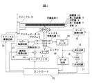
以下、本発明の実施形態を説明する。図1は、本発明の装置構成の一実施形態を示す。ここにおいて、1はレーザ、2,4はレンズ、5は記録媒体、12,13は光検出器、15は再生回路、20はレーザドライバ、21はパワー監視回路、22はサーボ駆動回路、23はコントローラ、24はスピンドル駆動回路をそれぞれ示す。
【0010】
情報記録再生装置は、レ−ザ1を中心とする光ヘッドと情報を記憶させるための記録媒体5とレーザドライバ20を中心とする記録処理系と光ヘッドから得られた再生信号を情報に変換する再生回路15を中心とした再生処理系から構成される。記録媒体5は、基板6に積層された第1記録層7、中間層8、第2記録層9および保護層10から構成される。
【0011】
上位ホストからの命令や情報デ−タはコントロ−ラ23において命令の解読や記録デ−タの変調および変調方式に対応する符号列に変換され、レーザドライバ20に伝送される。大容量化の手法としてゾ−ンごとに記録媒体の回転数を変えて内外周での記録密度を略一定とするM-CLV(Modified Constant Linear Velocity)方式と呼ばれる記録方法を採用した場合には、記録再生するゾ−ンに応じて、スピンドルの回転数を高精度に制御する必要がある。
【0012】
情報の記録再生を実施するための光スポットの位置制御を行なうサーボは、光検出器12の前に配置した円柱レンズ(図示せず)と光検出器(4分割)12によりプリアンプ4およびサーボ回路18によって、フォーカス誤差信号及びトラック誤差信号を得ることができ、前記誤差信号をコントローラ23に入力し、サーボ信号をコントローラ23からサーボ駆動回路22に出力し、アクチュエータ11をサーボ駆動回路22で制御することにより、光スポットの位置制御を行なう。
【0013】
高周波重畳回路19はレ−ザ1に起因するレ−ザ雑音を低減するために設けてあり、記録/消去時にはレ−ザの寿命の関点から高周波重畳を休止することもある。
【0014】
再生時はレ−ザ1を低出力発振させ、記録媒体5に入射させる。記録媒体5からの反射光はプリズム3で光路を分離して光検出器12に入射させる。光検出器12で光電変換した後、プリアンプ14で増幅し、再生回路15に入力する。再生回路15は波形等化回路、自動利得制御回路、二値化回路などから構成されており、入力された再生信号を二値化信号とする。
【0015】
再生回路15からの二値化信号はセルフクロッキングのためにPLL(Phase Locked Loop)16に入力される。PLL16で得られる二値化信号に同期した再生クロックと二値化信号はデ−タ弁別のために弁別回路17に入力され、その結果としてのデ−タ弁別信号はコントロ−ラ23に入力されデ−タが復調される。
【0016】
情報の記録を行なう場合、コントロ−ラ23からの正規の情報デ−タに応じて変調された記録パルス列がレーザドライバ20に出力される。レーザドライバ20はレーザ1を高出力発振させ、レ−ザ1から出た光はレンズ2で平行光となってプリズム3を通り、レンズ4により記録媒体5上に収束して符号列に応じた記録マークを記録する。
【0017】
図2は本発明における多層構造記録媒体での合焦点位置検出方法を示す。記録媒体5がスピンドル25に設定された場合、記録媒体5の内周または外周等に設けられた管理エリア40において、レンズ4を基板6から保護層10に向けて移動させることによって、図2の下側に記述された焦点ずれ量と焦点誤差信号振幅のグラフのように、第1記録層7と第2記録層9を光スポットが通過する時、右下がりの傾きで焦点誤差信号振幅が零になる。この2点間の焦点ずれΔLが第1記録層7と第2記録層9の焦点ずれ量であり、このΔLをコントローラ23で記憶しておくことにより、第1記録層7と第2記録層9の焦点位置を自在に変化させることができる。
【0018】
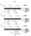
図3に本発明における多層構造記録媒体における情報記録方法を示す。図3は記録媒体5を半径方向に分割されたゾーンn31における記録方法を示してあり、 M-CLV(Modified Constant Linear Velocity)方式と呼ばれる記録方法を示す。図3(a)では第2記録層9のゾーンn31のスタート位置に光スポットを移動させるとともに、スピンドル25の回転数をスピンドル駆動回路24で制御する。記録媒体5の回転数が制御された後、第2記録層9のゾーンn31のスタート位置から記録を開始し、ゾーンn31の終了位置まで記録を行なう。
【0019】
次に、図2で説明したΔLだけ焦点位置を移動させるために、アクチュエータ11をサーボ駆動回路22で制御する。光スポットは第2記録層9から第1記録層7に移動し、さらに、第1記録層7のゾーンn31のスタート位置まで光スポットを移動させて、記録を開始した状態が図3(b)であり、第1記録層7のゾーンn31の終了位置まで記録を行なう。その後、図3(c)に示すようにゾーンn+1 32に光スポットを移動させ、スピンドル25の回転数をスピンドル駆動回路24で制御し、図2で説明したΔLだけ焦点位置を移動させ、第1記録層7から第2記録層9に光スポットを移動させ、第2記録層9のゾーンn+1 32のスタート位置から記録を再び開始する。
【0020】
以上のように第2記録層9から情報を記録することによって、記録していない第1記録層7でのレーザ光の散乱および吸収等による大きな光量変動を被ることなく、正確に情報を記録できる。また、ゾーン毎に第1記録層7と第2記録層9に情報を記録することができるので、ゾーンが変わることによるスピンドル25の回転制御時間を最小限に抑えることができる。
【0021】
さらに、記録中の光スポットの移動はゾーン内の移動で済むため、やはり、最小限の移動時間に抑えることができる。通常、CDサイズでの光スポットの移動距離は、約30〜40mm程度あり、安価な移動機構では、0.2〜0.3秒程度の移動時間が費やされる。したがって、ゾーンを1mm程度に設定すれば0.01秒程度の移動時間で済むため、第2記録層9のすべてのゾーンに情報を記録した後、第1記録層7に情報を記録する方式に比べて光スポットの移動時間を大きく削減することができる。
【0022】
また、第1記録層7が記録されることによるレーザ光の散乱および吸収等が小さい場合、図3(c)に示すゾーンn+1 32での焦点位置移動を行なわず、ゾーンn+1 32の第1記録層7から情報の記録を開始し、第1記録層7への情報記録が終了した後、第2記録層9に記録を行なうことで、ゾーン変更に伴う、情報記録再生装置の動作変更は、スピンドル25の回転制御のみとなり、情報記録時の転送レートを向上させることができる。
【0023】
以上のように、記録媒体の特性に応じて記録する順番を任意に変えた場合、図2で示した管理エリア40に記録順番を記録しておくことによって、スムーズに再生することができる。
【0024】
【発明の効果】
本発明によれば、多層構造を有する記録媒体への記録において、レーザ光が通過する記録層の記録情報が破壊されることなく、かつ、複数の記録層を通過することによる一定の光量変化だけによる変動に抑えることができるので、信頼性の高い情報の記録が行なえる。また、ゾーン毎に多層構造の記録層に情報を記録できるので、光スポットの移動時間を最小限にできるため、情報記録時の転送レートを向上させることができる。
【図面の簡単な説明】
【図1】本発明の一実施形態における情報記録再生装置構成を示す構成図。
【図2】本発明の一実施形態における多層構造記録媒体での合焦点位置検出方法を示す構成図。
【図3】本発明の一実施形態における多層構造記録媒体における情報記録方法を示す図。
【符号の説明】
1…レーザ、4…レンズ、5…記録媒体、6…基板、7…第1記録層、8…中間層、9…第2記録層、10…保護層、22…サーボ駆動回路、23…コントローラ、24…スピンドル駆動回路、25…スピンドル、31…ゾーンn、40…管理エリア、41…ゾーンm。[0001]
BACKGROUND OF THE INVENTION
The present invention relates to an information recording / reproducing apparatus for recording / reproducing information on an information recording medium, and more particularly to an information recording method and information recording / reproducing apparatus for recording information by a recording method using laser light recording.
[0002]
[Prior art]
As a technique for recording and reproducing information on an information recording medium using a laser beam, an optical disk device or the like has already been put into practical use, and one of the rewritable optical disk devices is reversible between crystal and amorphous. There is a phase change optical disk using state change. In order to obtain these two states, the information recording medium is heated to the melting point or higher by irradiating it with high power (recording power) and then rapidly cooled to make it an amorphous state, which is an intermediate power between the high power and the reproduction power. By irradiating (erasing power) and raising the temperature of the information recording medium to the crystallization temperature and then slowly cooling it, it becomes a crystalline state and can be overwritten by a single laser beam.
[0003]
Conventionally, with respect to the recording of information by the above recording method, as described in DVD Specifications for Rewritable Disc (DVD-RAM)
[0004]
[Problems to be solved by the invention]
The above-mentioned prior art does not consider a recording method of a multilayer structure in which a plurality of recording layers in which information is stored is arranged three-dimensionally with respect to a method capable of recording information, and is recorded by recording information. There have been problems such as large fluctuations in the amount of laser light due to scattering and absorption when the laser light passes through the recording layer, and information on the already recorded recording layer being destroyed.
[0005]
Further, in a recording method in which a recording layer in which information is stored has a multilayer structure in which a plurality of three-dimensionally arranged recording layers are divided, and a recording area is subdivided, and rotation control of the recording medium is required according to the subdivided recording area, By recording information on a recording layer having a multilayer structure as in the read-only information reading method, when information is recorded on the recording layer from the inner periphery to the outer periphery, the outer periphery is changed to the inner periphery. It is necessary to move the laser beam or the recording medium toward the target, and when the rotation is controlled by the M-CLV (Modified Constant Linear Velocity) method, the number of rotations needs to be increased by about twice. Since these operation times become very long, the time involved in recording and reproducing information is also long, and there is a problem that the information transfer rate is greatly reduced.
[0006]
SUMMARY OF THE INVENTION An object of the present invention is to solve the above-mentioned problems, and in a multi-layered recording method in which a plurality of recording layers in which information is stored is arranged three-dimensionally, by considering the order in which information is recorded, a laser It is an object of the present invention to provide an information recording method for suppressing the time for moving light or a recording medium and the rotation control time of the recording medium.
[0007]
[Means for Solving the Problems]
In order to achieve the above object, the present invention uses the configuration described in the claims as an example.
[0009]
DETAILED DESCRIPTION OF THE INVENTION
Embodiments of the present invention will be described below. FIG. 1 shows an embodiment of the apparatus configuration of the present invention. Here, 1 is a laser, 2 and 4 are lenses, 5 is a recording medium, 12 and 13 are photodetectors, 15 is a reproduction circuit, 20 is a laser driver, 21 is a power monitoring circuit, 22 is a servo drive circuit, and 23 is A
[0010]
The information recording / reproducing apparatus converts an optical head centered on the
[0011]
The command and information data from the host are converted into a code string corresponding to the decoding of the command and the modulation and modulation method of the recording data by the controller 23 and transmitted to the laser driver 20. When adopting a recording method called M-CLV (Modified Constant Linear Velocity) method that changes the rotation speed of the recording medium for each zone and makes the recording density at the inner and outer circumferences substantially constant as a method of increasing the capacity Therefore, it is necessary to control the rotational speed of the spindle with high accuracy in accordance with the zone to be recorded / reproduced.
[0012]
The servo for controlling the position of the light spot for recording / reproducing information is a
[0013]
The high frequency
[0014]
During reproduction, the
[0015]
The binarized signal from the reproduction circuit 15 is input to a PLL (Phase Locked Loop) 16 for self-clocking. The recovered clock synchronized with the binarized signal obtained by the
[0016]
When recording information, a recording pulse train modulated in accordance with regular information data from the controller 23 is output to the laser driver 20. The laser driver 20 oscillates the
[0017]
FIG. 2 shows a focus position detection method for a multilayer structure recording medium according to the present invention. When the recording medium 5 is set to the spindle 25, the
[0018]
FIG. 3 shows an information recording method in the multilayer structure recording medium of the present invention. FIG. 3 shows a recording method in a zone n31 obtained by dividing the recording medium 5 in the radial direction, and shows a recording method called an M-CLV (Modified Constant Linear Velocity) method. In FIG. 3A, the light spot is moved to the start position of the
[0019]
Next, the actuator 11 is controlled by the
[0020]
By recording information from the second recording layer 9 as described above, it is possible to accurately record information without suffering a large light amount fluctuation due to scattering and absorption of laser light in the first recording layer 7 that is not recorded. . Further, since information can be recorded on the first recording layer 7 and the second recording layer 9 for each zone, the rotation control time of the spindle 25 due to the change of the zone can be minimized.
[0021]
Furthermore, since the movement of the light spot during recording is only required to move within the zone, it is possible to keep the movement time to a minimum. Usually, the movement distance of the light spot in the CD size is about 30 to 40 mm, and an inexpensive movement mechanism consumes about 0.2 to 0.3 seconds. Therefore, if the zone is set to about 1 mm, a travel time of about 0.01 seconds is sufficient. Therefore, after information is recorded in all zones of the second recording layer 9, information is recorded on the first recording layer 7. Compared with this, the movement time of the light spot can be greatly reduced.
[0022]
Further, when the scattering and absorption of the laser beam due to the recording of the first recording layer 7 are small, the focal position is not moved in the zone n + 1 32 shown in FIG. 3C, and the first recording in the zone n + 1 32 is performed. By starting recording of information from the layer 7 and recording information on the second recording layer 9 after the information recording on the first recording layer 7 is completed, the operation change of the information recording / reproducing apparatus accompanying the zone change is as follows: Only the rotation control of the spindle 25 is performed, and the transfer rate at the time of information recording can be improved.
[0023]
As described above, when the recording order is arbitrarily changed according to the characteristics of the recording medium, the recording order can be recorded in the management area 40 shown in FIG.
[0024]
【The invention's effect】
According to the present invention, in recording on a recording medium having a multilayer structure, the recording information of the recording layer through which the laser beam passes is not destroyed, and only a certain amount of light change due to passing through the plurality of recording layers. Therefore, it is possible to record highly reliable information. In addition, since information can be recorded on the recording layer having a multilayer structure for each zone, the movement time of the light spot can be minimized, so that the transfer rate during information recording can be improved.
[Brief description of the drawings]
FIG. 1 is a configuration diagram showing a configuration of an information recording / reproducing apparatus according to an embodiment of the present invention.
FIG. 2 is a configuration diagram showing a focal position detection method in a multilayer structure recording medium according to an embodiment of the present invention.
FIG. 3 is a diagram showing an information recording method in a multilayer structure recording medium according to an embodiment of the present invention.
[Explanation of symbols]
DESCRIPTION OF
Claims (8)
前記第2記録層の一のゾーンに該ゾーンに応じた第1の記録速度で情報を記録する第1のステップと、
前記第1のステップの後に、前記第1記録層のゾーンのうち前記第1のステップで情報を記録したゾーンと略同一の半径位置にあるゾーンに前記第1の記録速度と略同一の記録速度で情報を記録する第2のステップと、
を有することを特徴とする情報記録方法。A plurality of recording layers including a first recording layer and a second recording layer positioned farther from the laser light incident surface than the first recording layer, wherein the plurality of recording layers are divided into a plurality of zones in the radial direction; An information recording method for recording information on any recording layer by irradiating a disk-shaped recording medium with laser light from one direction,
A first step of recording information in one zone of the second recording layer at a first recording speed corresponding to the zone ;
After the first step, a recording speed that is substantially the same as the first recording speed in a zone in the first recording layer that is at the same radial position as the zone in which information is recorded in the first step. A second step of recording information at
An information recording method characterized by comprising:
一のゾーン内部では前記ディスク状記録媒体の回転数が略一定速度で情報が記録されることを特徴とする情報記録方法。An information recording method according to claim 1, wherein
An information recording method characterized in that information is recorded at a substantially constant speed of the disc-shaped recording medium within one zone.
前記第2のステップの後に、前記第2記録層のうち前記第1のステップで情報を記録したゾーンとは異なるゾーンに情報を記録する第3のステップを有することを特徴とする情報記録方法。An information recording method according to claim 1, wherein
An information recording method comprising: after the second step, a third step of recording information in a zone different from the zone in which information is recorded in the first step of the second recording layer.
前記第2のステップの後に、前記第1記録層のうち前記第2のステップで情報を記録したゾーンとは異なるゾーンに情報を記録する第4のステップを有することを特徴とする情報記録方法。An information recording method according to claim 1, wherein
An information recording method comprising: after the second step, a fourth step of recording information in a zone different from the zone in which information is recorded in the second step of the first recording layer.
情報を記録した順番等を前記ディスク状記録媒体の所定のエリアに記録することを特徴とする情報記録方法。An information recording method according to claim 1, wherein
An information recording method for recording the order in which information is recorded in a predetermined area of the disc-shaped recording medium.
前記ディスク状記録媒体に情報を記録する前に、前記複数の記録層の焦点位置を検出しておくことを特徴とする情報記録方法。An information recording method according to claim 1, wherein
An information recording method comprising: detecting focal positions of the plurality of recording layers before recording information on the disc-shaped recording medium.
前記各記録層のうち前記レーザ光の入射面から遠い記録層の平面内の細分化された記録エリアのうち第1の記録エリアに該第1の記録エリアに応じた第1の記録速度で情報を記録し、前記第1のエリアへの記録の後に、
前記各記録層のうち前記レーザ光の入射面に近い記録層の平面内の細分化された記録エリアのうち前記第1の記録エリアと略同一の半径位置にある第2の記録エリアに前記第1の記録速度と略同一の記録速度で情報を記録し、
立体的に複数配置される記録層に順次情報を記録することを特徴とする多層構造記録媒体における情報記録方法。An information recording medium is irradiated with an oscillated laser beam to form a recording part that is physically different from an unrecorded part of information in a recording area on the information recording medium. An information recording method for recording information on a recording medium having a multilayer structure in which a plurality of recording layers to be accumulated are arranged three-dimensionally, and a recording area in a plane of each recording layer is subdivided,
Of the respective recording layers , information is recorded at the first recording speed corresponding to the first recording area in the first recording area among the segmented recording areas in the plane of the recording layer far from the incident surface of the laser beam . And after recording in the first area,
Of the respective recording layers, the second recording area at the same radial position as the first recording area among the subdivided recording areas in the plane of the recording layer close to the laser light incident surface . Information is recorded at a recording speed substantially the same as the recording speed of 1 ,
An information recording method for a multilayer structure recording medium, wherein information is sequentially recorded on a plurality of three-dimensionally arranged recording layers.
前記レーザ光を照射するレーザと、
前記レーザ光を前記ディスク状記録媒体へ集光させるレンズと、
前記レーザ及び前記レンズを駆動する制御部とを備え、
前記制御部は前記レーザを駆動し前記第2記録層の一のゾーンに該ゾーンに応じた第1の記録速度で情報を記録し、
その後、前記制御部は前記レーザ及び前記レーザを駆動し、前記第1記録層のゾーンのうち前記第2記録層に情報を記録したゾーンと略同一の半径位置にあるゾーンに前記第1の記録速度と略同一の記録速度で情報を記録する、
ことを特徴とする情報記録装置。A plurality of recording layers including a first recording layer and a second recording layer positioned farther from the laser light incident surface than the first recording layer, wherein the plurality of recording layers are divided into a plurality of zones in the radial direction; An information recording apparatus for recording information on any recording layer by irradiating a disc-shaped recording medium with laser light from one direction,
A laser for irradiating the laser beam;
A lens for condensing the laser beam onto the disc-shaped recording medium;
A controller for driving the laser and the lens,
The control unit drives the laser to record information in one zone of the second recording layer at a first recording speed corresponding to the zone ,
Thereafter, the control unit drives the laser and the laser, the first recording zone in the zone and substantially the same radial position for recording information on the second recording layer of the zone of the first recording layer Record information at approximately the same recording speed as the speed ,
An information recording apparatus characterized by that.
Priority Applications (1)
| Application Number | Priority Date | Filing Date | Title |
|---|---|---|---|
| JP19259199A JP4349692B2 (en) | 1999-07-07 | 1999-07-07 | Information recording method and information recording apparatus |
Applications Claiming Priority (1)
| Application Number | Priority Date | Filing Date | Title |
|---|---|---|---|
| JP19259199A JP4349692B2 (en) | 1999-07-07 | 1999-07-07 | Information recording method and information recording apparatus |
Related Child Applications (1)
| Application Number | Title | Priority Date | Filing Date |
|---|---|---|---|
| JP2006207365A Division JP4576360B2 (en) | 2006-07-31 | 2006-07-31 | Information recording method in multilayer structure recording medium |
Publications (3)
| Publication Number | Publication Date |
|---|---|
| JP2001023170A JP2001023170A (en) | 2001-01-26 |
| JP2001023170A5 JP2001023170A5 (en) | 2004-07-15 |
| JP4349692B2 true JP4349692B2 (en) | 2009-10-21 |
Family
ID=16293833
Family Applications (1)
| Application Number | Title | Priority Date | Filing Date |
|---|---|---|---|
| JP19259199A Expired - Fee Related JP4349692B2 (en) | 1999-07-07 | 1999-07-07 | Information recording method and information recording apparatus |
Country Status (1)
| Country | Link |
|---|---|
| JP (1) | JP4349692B2 (en) |
Families Citing this family (5)
| Publication number | Priority date | Publication date | Assignee | Title |
|---|---|---|---|---|
| JP4268764B2 (en) | 2001-02-09 | 2009-05-27 | パイオニア株式会社 | Information recording device |
| US7515519B2 (en) | 2004-09-17 | 2009-04-07 | Pioneer Corporation | Information recording medium, information recording device and method, and computer program |
| JP4507205B2 (en) | 2004-09-17 | 2010-07-21 | パイオニア株式会社 | Information recording medium, information recording apparatus and method, information reproducing apparatus and method, and computer program |
| JP4213128B2 (en) | 2005-02-25 | 2009-01-21 | 株式会社リコー | Recording method, program, recording medium, and information recording apparatus |
| JP6429124B2 (en) | 2015-03-27 | 2018-11-28 | パナソニックIpマネジメント株式会社 | Optical disc apparatus, method and computer program |
-
1999
- 1999-07-07 JP JP19259199A patent/JP4349692B2/en not_active Expired - Fee Related
Also Published As
| Publication number | Publication date |
|---|---|
| JP2001023170A (en) | 2001-01-26 |
Similar Documents
| Publication | Publication Date | Title |
|---|---|---|
| JP4605147B2 (en) | Optical recording method, optical recording apparatus, and multilayer optical recording medium for multilayer optical recording medium | |
| JP4605148B2 (en) | Optical recording method and optical recording apparatus for multilayer optical recording medium | |
| JP3887915B2 (en) | Recording medium driving apparatus and driving method thereof | |
| JP4200335B2 (en) | Information recording medium, and information recording apparatus and method | |
| US20020051414A1 (en) | Multi-layer information recording medium and recording apparatus for the same | |
| US7158458B2 (en) | Method and apparatus for recording/reproducing information with respect to optical recording medium | |
| JP4349692B2 (en) | Information recording method and information recording apparatus | |
| JP2006040446A (en) | Optical disk and information reproducing apparatus | |
| RU2314579C2 (en) | Optical recording data carrier, method of data recording/playing from/to optical recording carrier and device for recording/playing dta onto/from recording data carrier | |
| KR100685342B1 (en) | Information recording/reproducing method and information recording/reproducing apparatus | |
| JP3696438B2 (en) | Recording / reproducing apparatus and recording medium | |
| JPH1079126A (en) | Accessing method for optical disk device | |
| JP4576360B2 (en) | Information recording method in multilayer structure recording medium | |
| JP2001236674A (en) | Optical pickup device | |
| JP4154256B2 (en) | Optical information recording medium recording / reproducing apparatus and optical information recording medium recording / reproducing method | |
| JP2010287308A (en) | Information recording method in multilayered structure recording medium | |
| JP2000251383A5 (en) | Disk drive device, recording layer identification method | |
| JP4212460B2 (en) | Optical disc apparatus and information reproducing method | |
| US20090028041A1 (en) | Information Recording Medium, Information Recording Apparatus and Information Recording Method, and Computer Program | |
| KR100759910B1 (en) | Information recording medium and information recording device and method | |
| JP2768466B2 (en) | Information recording method for optical recording medium | |
| JP2617220B2 (en) | Optical memory device | |
| JP2000311343A (en) | Optical information recording media and its recording and reproducing method and optical information recording and reproducing device | |
| JP2011159378A (en) | Optical disk drive | |
| JPH0954954A (en) | Information recording/reproducing device |
Legal Events
| Date | Code | Title | Description |
|---|---|---|---|
| A977 | Report on retrieval |
Free format text: JAPANESE INTERMEDIATE CODE: A971007 Effective date: 20060309 |
|
| A131 | Notification of reasons for refusal |
Free format text: JAPANESE INTERMEDIATE CODE: A131 Effective date: 20060322 |
|
| RD01 | Notification of change of attorney |
Free format text: JAPANESE INTERMEDIATE CODE: A7421 Effective date: 20060417 |
|
| A521 | Written amendment |
Free format text: JAPANESE INTERMEDIATE CODE: A523 Effective date: 20060510 |
|
| A02 | Decision of refusal |
Free format text: JAPANESE INTERMEDIATE CODE: A02 Effective date: 20060530 |
|
| A521 | Written amendment |
Free format text: JAPANESE INTERMEDIATE CODE: A523 Effective date: 20060731 |
|
| A911 | Transfer of reconsideration by examiner before appeal (zenchi) |
Free format text: JAPANESE INTERMEDIATE CODE: A911 Effective date: 20060810 |
|
| A912 | Removal of reconsideration by examiner before appeal (zenchi) |
Free format text: JAPANESE INTERMEDIATE CODE: A912 Effective date: 20060901 |
|
| A01 | Written decision to grant a patent or to grant a registration (utility model) |
Free format text: JAPANESE INTERMEDIATE CODE: A01 |
|
| A61 | First payment of annual fees (during grant procedure) |
Free format text: JAPANESE INTERMEDIATE CODE: A61 Effective date: 20090721 |
|
| FPAY | Renewal fee payment (event date is renewal date of database) |
Free format text: PAYMENT UNTIL: 20120731 Year of fee payment: 3 |
|
| FPAY | Renewal fee payment (event date is renewal date of database) |
Free format text: PAYMENT UNTIL: 20130731 Year of fee payment: 4 |
|
| LAPS | Cancellation because of no payment of annual fees |