JP4347203B2 - Recording medium storage device and image forming apparatus - Google Patents
Recording medium storage device and image forming apparatus Download PDFInfo
- Publication number
- JP4347203B2 JP4347203B2 JP2004350583A JP2004350583A JP4347203B2 JP 4347203 B2 JP4347203 B2 JP 4347203B2 JP 2004350583 A JP2004350583 A JP 2004350583A JP 2004350583 A JP2004350583 A JP 2004350583A JP 4347203 B2 JP4347203 B2 JP 4347203B2
- Authority
- JP
- Japan
- Prior art keywords
- recording medium
- gear
- medium guide
- storage device
- paper cassette
- Prior art date
- Legal status (The legal status is an assumption and is not a legal conclusion. Google has not performed a legal analysis and makes no representation as to the accuracy of the status listed.)
- Expired - Fee Related
Links
Images


Description
本発明は、記録媒体収納装置及び画像形成装置に関するものである。 The present invention relates to a recording medium storage device and an image forming apparatus.
従来、プリンタ等の画像形成装置に取り付けられた印刷紙等の記録媒体を収納する記録媒体収納装置においては、収納された記録媒体の位置を整列させるための記録媒体ガイドを位置決めする手段が配設されている(例えば、特許文献1参照。)。 2. Description of the Related Art Conventionally, in a recording medium storage device for storing a recording medium such as printing paper attached to an image forming apparatus such as a printer, a means for positioning a recording medium guide for aligning the position of the stored recording medium is provided. (For example, refer to Patent Document 1).
図2は従来の記録媒体収納装置の概略図である。 FIG. 2 is a schematic view of a conventional recording medium storage device.
この場合、図に示されるように、記録媒体ガイド13を位置決めする手段として、記録媒体収納装置11の底面に配設された記録媒体ガイド位置決め用溝12、及び、記録媒体ガイド13に配設された記録媒体位置決め用突起14を使用する。そして、前記記録媒体ガイド位置決め用溝12と記録媒体位置決め用突起14とを嵌(かん)合させることによって、各記録媒体の寸法に合わせた位置に記録媒体ガイド13を位置決めする。
In this case, as shown in the figure, as a means for positioning the
図3は従来の他の記録媒体収納装置の概略図である。 FIG. 3 is a schematic view of another conventional recording medium storage device.
また、他の例においては、図3に示されるように、記録媒体ガイド13を位置決めする手段として、記録媒体ガイド13に形成されたラック15の記録媒体ガイド位置決め用突起16を使用する。そして、該記録媒体ガイド位置決め用突起16をリブ側面に配設された記録媒体ガイド位置決め用溝12と嵌合させることによって、各記録媒体の寸法に合わせた位置に記録媒体ガイド13を位置決めする。
In another example, as shown in FIG. 3, the recording medium
図4は従来の更に他の記録媒体収納装置の概略図である。 FIG. 4 is a schematic view of still another conventional recording medium storage device.
更に他の例においては、図4に示されるように、記録媒体ガイド13を位置決めする手段として、記録媒体ガイド13に形成されたラック15の弾性形状部分17を使用する。そして、該弾性形状部分17を記録媒体収納装置11に押圧させ、その部分で発生する摩擦力で記録媒体ガイド13を停止して位置決めするようになっている。
In still another example, as shown in FIG. 4, the
なお、前述されたいずれの例においても、記録媒体ガイド13を記録媒体の寸法に合わせて左右方向に動かすための手段としては、ラック15に係合させたギヤ18が用いられる。
しかしながら、前記従来の画像形成装置においては、記録媒体収納装置11が樹脂成形によって製作されているので、記録媒体ガイド位置決め用溝12の肉厚強度を確保する必要があるため、記録媒体収納装置11の底面に配設された記録媒体ガイド位置決め用溝12の配列寸法を短くすることができなかった。そのため、前記記録媒体ガイド位置決め用溝12は、実際には、1〜2〔mm〕間隔で配設されている。そして、記録媒体ガイド13の位置決め精度は前記記録媒体ガイド位置決め用溝12の配列寸法に依存するので、記録媒体ガイド13の位置決めは、1〜2〔mm〕の間隔でしか行うことができなかった。そのため、1〔mm〕以下の間隔で記録媒体の寸法ばらつきを補正して整列することができなかった。
However, in the conventional image forming apparatus, since the recording
また、記録媒体ガイド13に形成されたラック15の弾性形状部分17の押圧による摩擦力を利用する場合、記録媒体収納装置11の記録媒体収納枚数が多いと、記録媒体の重量を支えるだけの荷重を作用させるためには弾性形状部分17に過大な力が加わってしまい、塑性変形を起こして記録媒体の重量を支える押圧が得られなくなってしまう。
Further, when the frictional force generated by the pressing of the
本発明は、前記従来の問題点を解決して、記録媒体ガイドのラックに係合するギヤよりも大径のギヤの回転を規制部材で規制するようにして、記録媒体ガイドの位置決め精度が高く、記録媒体収納枚数が多くても位置ずれが発生することがない記録媒体収納装置及び画像形成装置を提供することを目的とする。 The present invention solves the above-mentioned conventional problems, and restricts the rotation of a gear having a larger diameter than the gear engaged with the rack of the recording medium guide by the regulating member so that the positioning accuracy of the recording medium guide is high. Another object of the present invention is to provide a recording medium storage device and an image forming apparatus in which positional deviation does not occur even when the number of recording medium storage is large.
そのために、本発明の記録媒体収納装置においては、記録媒体を収納する記録媒体収納装置であって、それぞれにラックが形成された第1及び第2の記録媒体ガイドと、それぞれの前記ラックに係合し、前記第1及び第2の記録媒体ガイドを連動させる第1ギヤと、該第1ギヤとともに2段ギヤを形成する第2ギヤと、該第2ギヤの回転を規制する第2ギヤ規制部材と、該第2ギヤ規制部材と接離可能な第2ギヤ規制部材の固定手段とを有し、前記第2ギヤの直径は前記第1ギヤの直径よりも大きい。 To this end, the recording medium storage device of the present invention is a recording medium storage device for storing a recording medium, and includes first and second recording medium guides each formed with a rack, and the racks. A first gear that interlocks the first and second recording medium guides, a second gear that forms a two-stage gear with the first gear, and a second gear restriction that restricts rotation of the second gear. A member and a fixing means for a second gear restricting member that can contact and separate from the second gear restricting member, and the diameter of the second gear is larger than the diameter of the first gear.
本発明によれば、記録媒体収納装置は、記録媒体ガイドのラックに係合するギヤよりも大径のギヤの回転を規制部材で規制するようになっている。そのため、記録媒体ガイドの位置決め精度が高く、記録媒体収納枚数が多くても位置ずれが発生することがない。 According to the present invention, the recording medium storage device restricts the rotation of the gear having a larger diameter than the gear engaged with the rack of the recording medium guide by the restricting member. For this reason, the positioning accuracy of the recording medium guide is high, and no positional deviation occurs even if the number of stored recording media is large.
以下、本発明の実施の形態について図面を参照しながら詳細に説明する。 Hereinafter, embodiments of the present invention will be described in detail with reference to the drawings.
図5は本発明の第1の実施の形態における画像形成装置の概略図、図6は本発明の第1の実施の形態における用紙カセットの斜視図である。 FIG. 5 is a schematic view of the image forming apparatus according to the first embodiment of the present invention, and FIG. 6 is a perspective view of the paper cassette according to the first embodiment of the present invention.
図5において、31は本実施の形態における画像形成装置としてのプリンタである。本実施の形態における画像形成装置は、ファクシミリ、複写機等の装置であってもよいが、ここではプリンタであるものとして説明する。そして、前記プリンタ31は、電子写真方式によって、印刷用紙、封筒、OHP(Over Head Projector)シート等の記録媒体30上に白黒やカラーの画像を形成するようになっている。なお、前記プリンタ31は、カラー画像を形成するものであってもよいが、ここでは、前記プリンタ31が白黒画像を形成するものである場合について説明する。この場合、LED(Light Emitting Diode)ヘッド55及び感光体ドラム54を備える画像形成部としてのイメージドラムユニット53が記録媒体30の搬送経路上に配設される。
In FIG. 5,
また、前記プリンタ31は、記録媒体30を多数枚収納する記録媒体収納装置としての用紙カセット21を有する。そして、該用紙カセット21に格納された記録媒体30の表面に接触して給紙ローラ56が配設されている。
The
そして、前記搬送経路におけるイメージドラムユニット53の下流側に、前記記録媒体30上の画像の定着を行う定着部57が配設されている。なお、該定着部57は、その内部に上定着ローラ及び下定着ローラを備える。また、前記搬送経路における定着部57の下流側に排紙トレイ58が配設されている。
A
本実施の形態において、前記用紙カセット21は、プリンタ31に脱着可能に装着され、内部に記録媒体30が収納される。そして、前記用紙カセット21は、プリンタ31に記録媒体30の左右位置を正しく整列させ供給する機能を有している。
In the present embodiment, the
この場合、用紙カセット21は、図6に示されるように、記録媒体30の後端の位置を整列させるテールガイド22を備える。そして、該テールガイド22は、記録媒体30の大きさに合わせて、用紙カセット21の床面に形成されたテールガイド案内溝23に沿って矢印Aで示される方向に移動し、位置を調整することができる。また、前記用紙カセット21は、記録媒体30の左右の位置を整列させる第1の記録媒体ガイド35及び第2の記録媒体ガイド36を備える。そして、前記第1の記録媒体ガイド35及び第2の記録媒体ガイド36は、記録媒体30の大きさに合わせて、用紙カセット21の床面に形成された第1の記録媒体ガイド案内溝26及び第2の記録媒体ガイド案内溝27に沿って矢印Dで示される方向に移動し、位置を調整することができる。
In this case, the
次に、前記第1の記録媒体ガイド35及び第2の記録媒体ガイド36を移動させるための機構について説明する。
Next, a mechanism for moving the first
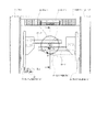
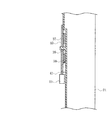
図1は本発明の第1の実施の形態における用紙カセットの記録媒体ガイド機構を示す概略図、図7は本発明の第1の実施の形態における図1のA−A断面図である。 FIG. 1 is a schematic diagram showing a recording medium guide mechanism of a paper cassette in the first embodiment of the present invention, and FIG. 7 is a cross-sectional view taken along line AA of FIG. 1 in the first embodiment of the present invention.
図1及び7に示されるように、前記第1の記録媒体ガイド35及び第2の記録媒体ガイド36には、一体又は別体で構成されたラック37及びラック38が、それぞれ、結合されている。前記ラック37及びラック38の中間位置には、ラック37及びラック38と係合し、ラック37及びラック38とともに前記第1の記録媒体ガイド35及び第2の記録媒体ガイド36を左右方向に連動させる第1ギヤ39が配設される。前記ラック37及びラック38には、前記第1ギヤ39と係合する範囲に歯型が形成されていて、第1ギヤ39の円周上全域に配設された歯型と係合する。
As shown in FIGS. 1 and 7, the first
前記第1ギヤ39の回転軸と同軸上には、第1ギヤ39と別体又は一体で成形された第2ギヤ40が配設される。該第2ギヤ40は、第1ギヤ39と別体で成形されている場合には、第1ギヤ39と結合され、第1ギヤ39と同時に回転する構造になっている。前記第2ギヤ40の円周上全域には、前記第1ギヤ39と同様に歯型が形成されているが、第1ギヤ39よりもギヤ直径を大きくし、円周上に歯型が形成されたギヤ減速比を有する2段ギヤとして構成されている。
A
さらに、前記第2ギヤ40の歯型は、用紙カセット21と一体又は別体で成形された第2ギヤ規制部材41の先端部と係合する。なお、前記用紙カセット21の床面には、各種媒体寸法の左右方向位置を示し、第1の記録媒体ガイド35及び第2の記録媒体ガイド36を位置決めするときの目安とするための媒体寸法位置目印42が表示される。
Further, the tooth shape of the
次に、前記構成の用紙カセット21の動作について説明する。
Next, the operation of the
まず、オペレータは、記録媒体30を用紙カセット21に格納し、第1の記録媒体ガイド35及び第2の記録媒体ガイド36の位置を記録媒体30の左右方向の寸法に合わせるために、用紙カセット21の中央方向の第1ギヤ39側に向かって第1の記録媒体ガイド35及び第2の記録媒体ガイド36を押して移動させる。第1の記録媒体ガイド35及び第2の記録媒体ガイド36が、相互の間隔が狭まる方向、すなわち、中央に向かって移動すると、第1の記録媒体ガイド35及び第2の記録媒体ガイド36に結合されたラック37及びラック38も用紙カセット21の中央に向かって動作する。
First, the operator stores the
前記ラック37及びラック38に係合された第1ギヤ39はラック37及びラック38の移動方向に回転を始める。これにより、前記第1ギヤ39と結合又は一体化された第2ギヤ40も第1ギヤ39と同方向に回転を始める。そして、第2ギヤ40が回転すると、用紙カセット21に配設された第2ギヤ規制部材41の先端部と第2ギヤ40の円周上に形成された歯型とは、第2ギヤ規制部材41の弾性力によって、嵌合と離脱とを、すなわち、係合と係合解除とを繰り返す。
The
そして、第1の記録媒体ガイド35及び第2の記録媒体ガイド36が用紙カセット21に収納された記録媒体30と接した段階、又は、収納しようとしている記録媒体30の寸法に対して、用紙カセット21に表示されている媒体寸法位置目印42と第1の記録媒体ガイド35及び第2の記録媒体ガイド36の位置とが一致した段階で、オペレータは第1の記録媒体ガイド35及び第2の記録媒体ガイド36を押す操作を停止する。このとき、第2ギヤ規制部材41の先端部と第2ギヤ40の円周上に形成された歯型とが係合した位置で第1の記録媒体ガイド35及び第2の記録媒体ガイド36が位置決めされる。
The first and second recording medium guides 35 and 36 are in contact with the
また、寸法の小さい記録媒体30から寸法の大きい記録媒体30に合わせるために、第1の記録媒体ガイド35及び第2の記録媒体ガイド36を移動させる場合、オペレータは、第1の記録媒体ガイド35及び第2の記録媒体ガイド36を前述された第1ギヤ39側とは反対側に向けて押し、第1の記録媒体ガイド35及び第2の記録媒体ガイド36の相互間隔が広がる方向に動作させる。この場合、用紙カセット21に配設された第2ギヤ規制部材41の先端部と第2ギヤ40の円周上に形成された歯型は、前述された作用と同様に第2ギヤ規制部材41の弾性力によって嵌合と離脱とを、すなわち、係合と係合解除とを繰り返す。そして、オペレータが第1の記録媒体ガイド35及び第2の記録媒体ガイド36を押す操作を停止した段階で、第2ギヤ規制部材41の先端部と第2ギヤ40の円周上に形成された歯型とが係合した位置において、第1の記録媒体ガイド35及び第2の記録媒体ガイド36が位置決めされる。
Further, when the first
このように、本実施の形態においては、第1の記録媒体ガイド35及び第2の記録媒体ガイド36を左右方向に連動させるギヤを第1ギヤ39に第2ギヤ40という異なるギヤを組み合わせて減速比を有する2段ギヤを形成し、第2ギヤ40の円周部分で第1の記録媒体ガイド35及び第2の記録媒体ガイド36の位置決めを行うようになっている。そのため、第2ギヤ40の円周部分で定義した位置決めの間隔は、第1ギヤ39の部分ではギヤの減速比に応じて小さくなる。
As described above, in the present embodiment, a gear that links the first
例えば、第1ギヤ39の直径を20〔mm〕とし、第2ギヤ40の直径を60〔mm〕とし、第2ギヤ40の歯幅を2〔mm〕とした場合、第1ギヤ39の部分での位置決め間隔は、
(20÷60)×2=0.67〔mm〕
となる。これにより、第1ギヤ39の部分の位置決め間隔を従来よりも小さくすることができ、第1の記録媒体ガイド35及び第2の記録媒体ガイド36の位置決めを高い精度で行うことができる。そのため、記録媒体30の不整列に起因する記録媒体30の給紙時の斜行を防止することができる。
For example, when the diameter of the
(20 ÷ 60) × 2 = 0.67 [mm]
It becomes. Thereby, the positioning interval of the
また、第1の記録媒体ガイド35及び第2の記録媒体ガイド36を保持するために必要な力であって、第2ギヤ規制部材41と第2ギヤ40との係合部で必要となる力である保持力F2を、ラック37及びラック38と第1ギヤ39との係合部で必要となる保持力F1よりも、ギヤの減速比に応じて、低減させることができる。したがって、保持力F2によって発生する第2ギヤ規制部材41への応力も、ギヤの減速比に応じて、低減させることができるので、第2ギヤ規制部材41のへたりを防止することができる。そのため、用紙カセット21をプリンタ31へ挿入する際に、記録媒体30の慣性力によって生じる第1の記録媒体ガイド35及び第2の記録媒体ガイド36の位置ずれを防止することができる。
Further, it is a force necessary to hold the first
また、前記保持力の低減分を記録媒体30の収納量増加による保持力の増加に振り替えることもでき、用紙カセット21の記録媒体30の収納量の向上に寄与する。なお、前記保持力の低減率はギヤの減速比と比例するので、第2ギヤ40の直径を大きくするほど低減効果が大きくなる。
Further, the reduction in the holding force can be transferred to an increase in holding force due to an increase in the storage amount of the
次に、本発明の第2の実施の形態について説明する。なお、第1の実施の形態と同じ構成を有するものについては、同じ符号を付与することによって、その説明を省略する。また、前記第1の実施の形態と同じ動作及び同じ効果についても、その説明を省略する。 Next, a second embodiment of the present invention will be described. In addition, about what has the same structure as 1st Embodiment, the description is abbreviate | omitted by providing the same code | symbol. The description of the same operation and the same effect as those of the first embodiment is also omitted.
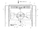
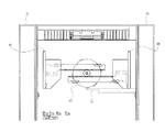
図8は本発明の第2の実施の形態における用紙カセットの記録媒体ガイド機構を示す概略図、図9は本発明の第2の実施の形態における図8のB−B断面図である。 FIG. 8 is a schematic view showing a recording medium guide mechanism of a paper cassette in the second embodiment of the present invention, and FIG. 9 is a sectional view taken along line BB in FIG. 8 in the second embodiment of the present invention.
本実施の形態においては、図8及び9に示されるように、プリンタ31側に固定片作用部45を配設し、用紙カセット21側には第2ギヤ規制部材41の固定手段としての固定片46、固定片リセットスプリング47、固定片リミッタ48、及び、固定片移動溝49が配設される。また、前記固定片46の先端には、第2ギヤの規制手段としての第2ギヤ補助規制部50が配設される。
In the present embodiment, as shown in FIGS. 8 and 9, a fixed
なお、本実施の形態においては、固定片リセットスプリング47としてねじりコイルスプリングを用いているが、固定片リセットスプリング47としては、圧縮コイルスプリング、引っ張りコイルスプリング、板ばね、樹脂成形品等も用いることができ、固定片46を移動させることができる弾性体であればいかなる種類のものであってもよい。その他の点の構成については、前記第1の実施の形態と同様であるので、説明を省略する。
In this embodiment, a torsion coil spring is used as the fixed piece reset
次に、本実施の形態における用紙カセット21の動作について説明する。
Next, the operation of the
図10は本発明の第2の実施の形態における固定片の動作を示す第1の図、図11は本発明の第2の実施の形態における固定片の動作を示す第2の図、図12は本発明の第2の実施の形態における固定片の動作を示す第3の図である。 FIG. 10 is a first diagram showing the operation of the fixed piece in the second embodiment of the present invention, and FIG. 11 is a second diagram showing the operation of the fixed piece in the second embodiment of the present invention. These are the 3rd figures which show operation | movement of the fixing piece in the 2nd Embodiment of this invention.
まず、用紙カセット21の挿入前に、用紙カセット21に配設された固定片リセットスプリング47が作用することによって、固定片リミッタ48の位置で固定片46が当接し停止している。
First, before the
そして、オペレーターは、プリンタ31に用紙カセット21を挿入する。固定片46は、プリンタ31への用紙カセット21の挿入が完了するまでの間、すなわち、挿入され続けると、プリンタ31に配設された固定片作用部45により図11に示されるように、用紙カセット21に配設された固定片移動溝49に沿って、第2ギヤ規制部材41側に移動を開始する。そして、前記用紙カセット21のプリンタ31への挿入が完了した位置で、固定片46は第2ギヤ規制部材41に当接して停止する。(図12)
また、図12に示されるように、固定片46の先端に配設された第2ギヤ補助規制部50が第2ギヤ40の歯型と係合する。前記第2ギヤ規制部材41は、固定片46によって固定されるので、第2ギヤ40に係合した状態が保持される。また、前記固定片46と第2ギヤ規制部材41との当接は、オペレータがプリンタ31から用紙カセット21を抜く操作を行うまで保持される。
Then, the operator inserts the
In addition, as shown in FIG. 12, the second gear
そして、用紙カセット21をプリンタ31から抜く場合、固定片46は、用紙カセット21に配設された固定片リセットスプリング47の付勢力によって、第2ギヤ規制部材41と離れ、固定片リミッタ48方向に移動を開始し、固定片46が固定片リミッタ48に当接した位置で停止する。この時点において、第2ギヤ40と第2ギヤ補助規制部50との係合は解除され、第1の記録媒体ガイド35及び第2の記録媒体ガイド36の操作によって第2ギヤ規制部材41の係合と係合解除とが可能となる。その他の点の動作については、前記第1の実施の形態と同様であるので、説明を省略する。
When the
このように、本実施の形態においては、第2ギヤ規制部材41に当接させる固定片46が配設されていることによって、プリンタ31に用紙カセット21を挿入する際に第2ギヤ規制部材41の動作が固定片46によって強制的に固定され、さらに、固定片46の先端に配設された第2ギヤ補助規制部50が第2ギヤ40の規制を補助する。そのため、二つの規制によって規制部分の強度が増し、記録媒体30の収納枚数の多い用紙カセット21であっても、該用紙カセット21をプリンタ31に挿入する際に、記録媒体30の慣性力によって生じる第1の記録媒体ガイド35及び第2の記録媒体ガイド36の位置ずれを防止することができ、記録媒体30の整列を保持することができる。
As described above, in the present embodiment, the fixed
また、固定片46による第2ギヤ規制部材41の規制、及び、第2ギヤ補助規制部50による第2ギヤ40の規制は、用紙カセット21をプリンタ31から抜いた際に固定片リセットスプリング47の作用によって自動的に解除されるので、第1の記録媒体ガイド35及び第2の記録媒体ガイド36の位置再設定動作の妨げになることもなく、操作性の良好な用紙カセット21を提供することができる。
Further, the restriction of the second
さらに、第2ギヤ規制部材41の係合力を弱くすることができるので、第1の記録媒体ガイド35及び第2の記録媒体ガイド36の移動時の負荷や接離による音も低くすることができる。
Furthermore, since the engagement force of the second
次に、本発明の第3の実施の形態について説明する。なお、第1及び第2の実施の形態と同じ構成を有するものについては、同じ符号を付与することによって、その説明を省略する。また、前記第1及び第2の実施の形態と同じ動作及び同じ効果についても、その説明を省略する。 Next, a third embodiment of the present invention will be described. In addition, about the thing which has the same structure as 1st and 2nd embodiment, the description is abbreviate | omitted by providing the same code | symbol. Also, the description of the same operations and effects as those of the first and second embodiments is omitted.
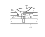
図13は本発明の第3の実施の形態における用紙カセットの記録媒体ガイド機構を示す概略図、図14は本発明の第3の実施の形態における図13のC−C断面図である。 FIG. 13 is a schematic view showing a recording medium guide mechanism of a paper cassette in the third embodiment of the present invention, and FIG. 14 is a sectional view taken along the line CC in FIG. 13 in the third embodiment of the present invention.
本実施の形態においては、図13及び14に示されるように、用紙カセット21のプリンタ31への挿入が完了したときに、該プリンタ31側に固定された作用部51が第2ギヤ規制部材41に直接当接するようになっている。その他の点の構成については、前記第2の実施の形態と同様であるので、説明を省略する。
In the present embodiment, as shown in FIGS. 13 and 14, when the insertion of the
次に、本実施の形態における用紙カセット21の動作について説明する。なお、本実施の形態における用紙カセット21の動作については、前記第2の実施の形態における用紙カセット21の動作とほぼ同様であるので、異なる部分だけを説明する。
Next, the operation of the
この場合、オペレータがプリンタ31に用紙カセット21を挿入すると、該用紙カセット21の挿入が完了する直前に第2ギヤ規制部材41が作用部51に接近し、用紙カセット21の挿入が完了すると、第2ギヤ規制部材41が作用部51に当接する。そして、前記第2ギヤ規制部材41の作用部51への当接は、用紙カセット21をプリンタ31から抜くことによって解除される。
In this case, when the operator inserts the
このように、本実施の形態においては、規制部分の強度を増加させるということ以外の固定片46(図8)の機能を、第2ギヤ規制部材41及び作用部51だけで得ることができる。そのため、固定片46、固定片リセットスプリング47等の部材を削減することができ、第2ギヤ規制部材41周辺のスペースを小さくすることができる。特に、前記第2の実施の形態と比較して、小さい記録媒体30を収納する用紙カセット21や記録媒体30の収納枚数が中程度の用紙カセット21に対して有効である。
As described above, in the present embodiment, the function of the fixing piece 46 (FIG. 8) other than increasing the strength of the restricting portion can be obtained only by the second
次に、本発明の第4の実施の形態について説明する。なお、第1〜第3の実施の形態と同じ構成を有するものについては、同じ符号を付与することによって、その説明を省略する。また、前記第1〜第3の実施の形態と同じ動作及び同じ効果についても、その説明を省略する。 Next, a fourth embodiment of the present invention will be described. In addition, about the thing which has the same structure as 1st-3rd embodiment, the description is abbreviate | omitted by providing the same code | symbol. Explanation of the same operations and effects as those of the first to third embodiments is also omitted.
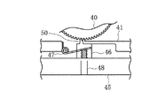
図15は本発明の第4の実施の形態における用紙カセットの記録媒体ガイド機構を示す概略図である。 FIG. 15 is a schematic view showing a recording medium guide mechanism of a paper cassette according to the fourth embodiment of the present invention.
本実施の形態においては、前記第1の実施の形態における第2ギヤ40に代えて、図15に示されるように、間欠第2ギヤ52が配設されている。そして、該間欠第2ギヤ52の歯型の一周分の周長は、第1の記録媒体ガイド35及び第2の記録媒体ガイド36の移動量と同じ長さに設定されている。さらに、前記間欠第2ギヤ52の円周上には、用紙カセット21に収納可能と定義された定形の記録媒体30の寸法に合わせた部分とその前後の数個だけに歯型が形成される。なお、前記間欠第2ギヤ52の円周上における定形の記録媒体30の寸法に該当しない範囲には、第2ギヤ規制部材41と係合しない直径寸法の円周が形成されている。
In the present embodiment, instead of the
次に、本実施の形態における用紙カセット21の動作について説明する。なお、本実施の形態における用紙カセット21の動作については、前記第1の実施の形態における用紙カセット21の動作とほぼ同様であるので、異なる部分だけを説明する。
Next, the operation of the
この場合、第2ギヤ規制部材41は、間欠第2ギヤ52と係合し、前記第1の実施の形態と同様に、第1の記録媒体ガイド35及び第2の記録媒体ガイド36の位置決めを行うことができる。しかし、前記間欠第2ギヤ52の円周上には、用紙カセット21に収納可能と定義された定形の記録媒体30の寸法に合わせた部分及びその前後の数個だけに歯型が形成されている。そのため、定形以外の記録媒体30の寸法範囲に第1の記録媒体ガイド35及び第2の記録媒体ガイド36が位置している場合、第2ギヤ規制部材41は、間欠第2ギヤ52と歯型による係合が行われない状態となり、第2ギヤ規制部材41の付勢力が第1の記録媒体ガイド35及び第2の記録媒体ガイド36に付加されない。
In this case, the second
このように、本実施の形態においては、記録媒体30の定形寸法以外の部分では第1の記録媒体ガイド35及び第2の記録媒体ガイド36に付勢力が発生しないようになっている。そのため、例えば、記録媒体30の寸法をA5からA6に切り替えようとした場合に、その間、第1の記録媒体ガイド35及び第2の記録媒体ガイド36の動作が滑らかに行われる。したがって、前記第1の実施の形態における位置決め精度の改善に加え、第1の記録媒体ガイド35及び第2の記録媒体ガイド36の操作性を改善することもできる。
Thus, in the present embodiment, no biasing force is generated in the first
なお、前記第1〜第4の実施の形態においては、画像形成装置が電子写真方式のプリンタである場合について説明したが、本発明において、画像形成装置は、電子写真方式やその他各種印刷方式を使用して記録媒体上に画像を形成する装置であれば、いかなる種類の装置であってもよく、例えば、複写機、ファクシミリ、MFP(複合型プリンタ:Multi Function Printer)等であってもよい。さらに、本発明における記録媒体収納装置は、画像形成装置の自動記録媒体給紙装置や手指し記録媒体給紙装置であってもよいし、原稿読み取り手段を有する複写機、ファクシミリ、MFP、イメージスキャナ、OCR等の画像読み取り装置の原稿媒体給紙装置に利用することもできる。 In the first to fourth embodiments, the case where the image forming apparatus is an electrophotographic printer has been described. However, in the present invention, the image forming apparatus employs an electrophotographic system or other various printing systems. Any type of device may be used as long as it can be used to form an image on a recording medium. For example, it may be a copying machine, a facsimile, an MFP (Multi Function Printer), or the like. Further, the recording medium storage device in the present invention may be an automatic recording medium feeding device or a manual recording medium feeding device of an image forming apparatus, or a copying machine, a facsimile, an MFP, an image scanner having a document reading unit. It can also be used for a document medium feeding device of an image reading device such as an OCR.
また、本発明は前記実施の形態に限定されるものではなく、本発明の趣旨に基づいて種々変形させることが可能であり、それらを本発明の範囲から排除するものではない。 The present invention is not limited to the above-described embodiment, and various modifications can be made based on the spirit of the present invention, and they are not excluded from the scope of the present invention.
21 用紙カセット
30 記録媒体
31 プリンタ
35 第1の記録媒体ガイド
36 第2の記録媒体ガイド
37、38 ラック
39 第1ギヤ
40 第2ギヤ
41 第2ギヤ規制部材
46 固定片
50 第2ギヤ補助規制部
52 間欠第2ギヤ
21
Claims (8)
(b)それぞれにラックが形成された第1及び第2の記録媒体ガイドと、
(c)それぞれの前記ラックに係合し、前記第1及び第2の記録媒体ガイドを連動させる第1ギヤと、
(d)該第1ギヤとともに2段ギヤを形成する第2ギヤと、
(e)該第2ギヤの回転を規制する第2ギヤ規制部材と、
(f)該第2ギヤ規制部材と接離可能な第2ギヤ規制部材の固定手段とを有し、
(g)前記第2ギヤの直径は前記第1ギヤの直径よりも大きいことを特徴とする記録媒体収納装置。 (A) A recording medium storage device for storing a recording medium,
(B) first and second recording medium guides each formed with a rack;
(C) a first gear that engages with each of the racks and interlocks the first and second recording medium guides;
(D) a second gear that forms a two-stage gear with the first gear;
(E) a second gear restricting member that restricts rotation of the second gear;
(F) a fixing means for the second gear restriction member that can contact and separate from the second gear restriction member;
(G) The recording medium storage device, wherein the diameter of the second gear is larger than the diameter of the first gear.
Priority Applications (1)
| Application Number | Priority Date | Filing Date | Title |
|---|---|---|---|
| JP2004350583A JP4347203B2 (en) | 2004-12-03 | 2004-12-03 | Recording medium storage device and image forming apparatus |
Applications Claiming Priority (1)
| Application Number | Priority Date | Filing Date | Title |
|---|---|---|---|
| JP2004350583A JP4347203B2 (en) | 2004-12-03 | 2004-12-03 | Recording medium storage device and image forming apparatus |
Publications (3)
| Publication Number | Publication Date |
|---|---|
| JP2006160391A JP2006160391A (en) | 2006-06-22 |
| JP2006160391A5 JP2006160391A5 (en) | 2007-04-12 |
| JP4347203B2 true JP4347203B2 (en) | 2009-10-21 |
Family
ID=36662836
Family Applications (1)
| Application Number | Title | Priority Date | Filing Date |
|---|---|---|---|
| JP2004350583A Expired - Fee Related JP4347203B2 (en) | 2004-12-03 | 2004-12-03 | Recording medium storage device and image forming apparatus |
Country Status (1)
| Country | Link |
|---|---|
| JP (1) | JP4347203B2 (en) |
Families Citing this family (3)
| Publication number | Priority date | Publication date | Assignee | Title |
|---|---|---|---|---|
| JP5023910B2 (en) * | 2007-09-18 | 2012-09-12 | セイコーエプソン株式会社 | Paper guide device |
| JP5994358B2 (en) * | 2012-04-25 | 2016-09-21 | 富士ゼロックス株式会社 | Medium container, image forming apparatus, and image reading apparatus |
| JP2014133659A (en) * | 2014-04-23 | 2014-07-24 | Oki Data Corp | Medium loading device and image formation device |
Family Cites Families (4)
| Publication number | Priority date | Publication date | Assignee | Title |
|---|---|---|---|---|
| JPH06329272A (en) * | 1993-05-19 | 1994-11-29 | Ricoh Co Ltd | Sheet processing device |
| JPH07257759A (en) * | 1994-03-23 | 1995-10-09 | Ricoh Co Ltd | Paper feed device |
| JPH107260A (en) * | 1996-06-21 | 1998-01-13 | Ricoh Co Ltd | Paper feed cassette |
| JP4096496B2 (en) * | 2000-06-16 | 2008-06-04 | 村田機械株式会社 | Paper feeder |
-
2004
- 2004-12-03 JP JP2004350583A patent/JP4347203B2/en not_active Expired - Fee Related
Also Published As
| Publication number | Publication date |
|---|---|
| JP2006160391A (en) | 2006-06-22 |
Similar Documents
| Publication | Publication Date | Title |
|---|---|---|
| US7584956B2 (en) | Image forming apparatus, sheet size detection device, and sheet size detection method | |
| US9884735B2 (en) | Sheet tray and sheet conveying apparatus | |
| JP6659119B2 (en) | Sheet storage device and image forming device | |
| JP4229129B2 (en) | Image forming apparatus | |
| US9714146B2 (en) | Sheet storage apparatus and image forming apparatus | |
| JP4229128B2 (en) | Image forming apparatus | |
| JP2004315230A (en) | Paper feeding device and image formation device | |
| JP4324562B2 (en) | Sheet size detection apparatus and image forming apparatus | |
| JP2006206319A (en) | Paper feeder and image forming device having the paper feeder | |
| US7703763B2 (en) | Sheet conveying devices and image recording apparatuses including the same | |
| US9085431B2 (en) | Sheet feed cassette | |
| US9671736B2 (en) | Unit moving apparatus and image forming apparatus | |
| JP4347203B2 (en) | Recording medium storage device and image forming apparatus | |
| JP5344578B2 (en) | Image forming apparatus | |
| JP6439246B2 (en) | Sheet transport device | |
| JP6618344B2 (en) | Sheet storage device and image forming apparatus | |
| JP2008162756A (en) | Image recording device | |
| JP4661628B2 (en) | Image forming apparatus | |
| JP2010006592A (en) | Sheet retaining device and image recording system | |
| JP6319978B2 (en) | Sheet feeding apparatus and image forming apparatus | |
| US10144603B2 (en) | Medium transportation device and recording apparatus | |
| JP5163414B2 (en) | Paper cassette | |
| JP4847832B2 (en) | Image forming apparatus and medium conveying apparatus | |
| JP2009083961A (en) | Paper feeding tray and image recording device | |
| US20060180976A1 (en) | Manual paper feeding device for image forming apparatus |
Legal Events
| Date | Code | Title | Description |
|---|---|---|---|
| A521 | Written amendment |
Free format text: JAPANESE INTERMEDIATE CODE: A523 Effective date: 20070223 |
|
| A621 | Written request for application examination |
Free format text: JAPANESE INTERMEDIATE CODE: A621 Effective date: 20070223 |
|
| A977 | Report on retrieval |
Free format text: JAPANESE INTERMEDIATE CODE: A971007 Effective date: 20081224 |
|
| A131 | Notification of reasons for refusal |
Free format text: JAPANESE INTERMEDIATE CODE: A131 Effective date: 20090113 |
|
| A521 | Written amendment |
Free format text: JAPANESE INTERMEDIATE CODE: A523 Effective date: 20090303 |
|
| A131 | Notification of reasons for refusal |
Free format text: JAPANESE INTERMEDIATE CODE: A131 Effective date: 20090414 |
|
| A521 | Written amendment |
Free format text: JAPANESE INTERMEDIATE CODE: A523 Effective date: 20090611 |
|
| TRDD | Decision of grant or rejection written | ||
| A01 | Written decision to grant a patent or to grant a registration (utility model) |
Free format text: JAPANESE INTERMEDIATE CODE: A01 Effective date: 20090714 |
|
| A01 | Written decision to grant a patent or to grant a registration (utility model) |
Free format text: JAPANESE INTERMEDIATE CODE: A01 |
|
| A61 | First payment of annual fees (during grant procedure) |
Free format text: JAPANESE INTERMEDIATE CODE: A61 Effective date: 20090715 |
|
| R150 | Certificate of patent or registration of utility model |
Free format text: JAPANESE INTERMEDIATE CODE: R150 |
|
| FPAY | Renewal fee payment (event date is renewal date of database) |
Free format text: PAYMENT UNTIL: 20120724 Year of fee payment: 3 |
|
| FPAY | Renewal fee payment (event date is renewal date of database) |
Free format text: PAYMENT UNTIL: 20130724 Year of fee payment: 4 |
|
| LAPS | Cancellation because of no payment of annual fees |