JP4346445B2 - Inflatable cover for use in cardiac surgery - Google Patents
Inflatable cover for use in cardiac surgery Download PDFInfo
- Publication number
- JP4346445B2 JP4346445B2 JP2003561480A JP2003561480A JP4346445B2 JP 4346445 B2 JP4346445 B2 JP 4346445B2 JP 2003561480 A JP2003561480 A JP 2003561480A JP 2003561480 A JP2003561480 A JP 2003561480A JP 4346445 B2 JP4346445 B2 JP 4346445B2
- Authority
- JP
- Japan
- Prior art keywords
- cover
- inflatable
- sheet
- patient
- cavity
- Prior art date
- Legal status (The legal status is an assumption and is not a legal conclusion. Google has not performed a legal analysis and makes no representation as to the accuracy of the status listed.)
- Expired - Fee Related
Links
Images


Classifications
-
- A—HUMAN NECESSITIES
- A61—MEDICAL OR VETERINARY SCIENCE; HYGIENE
- A61F—FILTERS IMPLANTABLE INTO BLOOD VESSELS; PROSTHESES; DEVICES PROVIDING PATENCY TO, OR PREVENTING COLLAPSING OF, TUBULAR STRUCTURES OF THE BODY, e.g. STENTS; ORTHOPAEDIC, NURSING OR CONTRACEPTIVE DEVICES; FOMENTATION; TREATMENT OR PROTECTION OF EYES OR EARS; BANDAGES, DRESSINGS OR ABSORBENT PADS; FIRST-AID KITS
- A61F7/00—Heating or cooling appliances for medical or therapeutic treatment of the human body
- A61F7/0097—Blankets with active heating or cooling sources
-
- A—HUMAN NECESSITIES
- A61—MEDICAL OR VETERINARY SCIENCE; HYGIENE
- A61F—FILTERS IMPLANTABLE INTO BLOOD VESSELS; PROSTHESES; DEVICES PROVIDING PATENCY TO, OR PREVENTING COLLAPSING OF, TUBULAR STRUCTURES OF THE BODY, e.g. STENTS; ORTHOPAEDIC, NURSING OR CONTRACEPTIVE DEVICES; FOMENTATION; TREATMENT OR PROTECTION OF EYES OR EARS; BANDAGES, DRESSINGS OR ABSORBENT PADS; FIRST-AID KITS
- A61F7/00—Heating or cooling appliances for medical or therapeutic treatment of the human body
- A61F2007/0001—Body part
-
- A—HUMAN NECESSITIES
- A61—MEDICAL OR VETERINARY SCIENCE; HYGIENE
- A61F—FILTERS IMPLANTABLE INTO BLOOD VESSELS; PROSTHESES; DEVICES PROVIDING PATENCY TO, OR PREVENTING COLLAPSING OF, TUBULAR STRUCTURES OF THE BODY, e.g. STENTS; ORTHOPAEDIC, NURSING OR CONTRACEPTIVE DEVICES; FOMENTATION; TREATMENT OR PROTECTION OF EYES OR EARS; BANDAGES, DRESSINGS OR ABSORBENT PADS; FIRST-AID KITS
- A61F7/00—Heating or cooling appliances for medical or therapeutic treatment of the human body
- A61F2007/0059—Heating or cooling appliances for medical or therapeutic treatment of the human body with an open fluid circuit
- A61F2007/006—Heating or cooling appliances for medical or therapeutic treatment of the human body with an open fluid circuit of gas
-
- A—HUMAN NECESSITIES
- A61—MEDICAL OR VETERINARY SCIENCE; HYGIENE
- A61F—FILTERS IMPLANTABLE INTO BLOOD VESSELS; PROSTHESES; DEVICES PROVIDING PATENCY TO, OR PREVENTING COLLAPSING OF, TUBULAR STRUCTURES OF THE BODY, e.g. STENTS; ORTHOPAEDIC, NURSING OR CONTRACEPTIVE DEVICES; FOMENTATION; TREATMENT OR PROTECTION OF EYES OR EARS; BANDAGES, DRESSINGS OR ABSORBENT PADS; FIRST-AID KITS
- A61F7/00—Heating or cooling appliances for medical or therapeutic treatment of the human body
- A61F7/02—Compresses or poultices for effecting heating or cooling
- A61F2007/0282—Compresses or poultices for effecting heating or cooling for particular medical treatments or effects
- A61F2007/0288—Compresses or poultices for effecting heating or cooling for particular medical treatments or effects during operations
Landscapes
- Health & Medical Sciences (AREA)
- Animal Behavior & Ethology (AREA)
- Biomedical Technology (AREA)
- Heart & Thoracic Surgery (AREA)
- Vascular Medicine (AREA)
- Life Sciences & Earth Sciences (AREA)
- Engineering & Computer Science (AREA)
- General Health & Medical Sciences (AREA)
- Public Health (AREA)
- Veterinary Medicine (AREA)
- Thermotherapy And Cooling Therapy Devices (AREA)
- External Artificial Organs (AREA)
- Prostheses (AREA)
Abstract
Description
発明の背景
関連出願に対する相互参照
この出願は、2002年1月17日に提出された仮出願連続番号第60/348,671号の利益を主張する。
Background of the Invention
CROSS-REFERENCE This application for the relevant application claims the benefit of Provisional Application Serial No. 60 / 348,671, filed on January 17, 2002.
発明の分野
この発明は、患者に用いるための膨張可能なカバーに関する。
The present invention relates to an inflatable cover for use with a patient.
関連技術の説明
血管形成などの特定の心臓手術は、カテーテルまたはその他の伸長する医療器具を患者の大腿部の大腿動脈に挿入し、伸長する医療器具を血管を通じて心臓に通すことを含む。
2. Description of Related Art Certain cardiac procedures, such as angioplasty, involve inserting a catheter or other elongating medical device into the femoral artery of a patient's femur and passing the elongating medical device through the blood vessel into the heart.
手術中に患者を過度に冷やすことは望ましくない。患者を温かい空気で包む強制空気加温カバーを含むさまざまな患者を温めるシステムが提案されている。しかし、患者の下半身を覆うための公知の強制空気加温カバーは、大腿動脈を通じた心臓手術を行なうために必要な、患者の大腿部への接近の妨げになる。 It is not desirable to overcool the patient during surgery. Various patient warming systems have been proposed, including a forced air warming cover that wraps the patient in warm air. However, known forced air warming covers to cover the patient's lower body prevent access to the patient's thigh, which is necessary for performing cardiac surgery through the femoral artery.
強制空気加温カバーは、カバーを温かい空気で膨張させるためにカバーに接続されるホースの使用によって動作する。強制空気加温カバーにおける空気吐出ホースの位置決めは、大腿動脈を通じた心臓手術を行なうことの妨げとなり得る。 A forced air warming cover operates by the use of a hose connected to the cover to inflate the cover with warm air. Positioning the air discharge hose in the forced air warming cover can interfere with performing cardiac surgery through the femoral artery.
使い捨ての強制空気加温カバーを滅菌単体として提供することも望ましい。しかし、カバーの包装を解いて患者の上に位置決めすることは、患者のまわりに確立された滅菌野を損なうおそれがある。 It is also desirable to provide a disposable forced air heating cover as a sterilized unit. However, unwrapping the cover and positioning it on the patient can damage the sterile field established around the patient.
加えて、強制空気加温カバーを膨張させるための空気吐出ホースは滅菌していないと考えられる。したがって、滅菌していない空気吐出ホースを強制空気加温カバーに接続して動作することも、患者のまわりに確立した滅菌野を損なうおそれがある。 In addition, it is considered that the air discharge hose for expanding the forced air heating cover is not sterilized. Therefore, operation by connecting a non-sterilized air discharge hose to the forced air warming cover may damage the sterilization field established around the patient.
したがって、当該技術分野においては、心臓手術において用いるための改善された強制空気加温カバーがなおも必要とされている。 Accordingly, there remains a need in the art for an improved forced air warming cover for use in cardiac surgery.
発明の概要
この発明に従う強制空気対流システムに対する膨張可能なカバーを用いることで、次のようなステップを含む心臓手術を行なうことができる。その心臓手術は、強制空気対流システムに対する膨張可能なカバーで患者を覆うステップを含み、その膨張可能なカバーはカバー内に少なくとも1つの分離可能な封止線を有し、その分離可能な封止線は分離されてスリットを形成してもよく、この心臓手術はさらに、スリットを通じて患者の下肢(たとえば大腿)動脈に接近するステップと、伸長する医療器具をスリットを通じて大腿動脈を通じて患者の心臓に向けて通すステップと、伸長する医療器具によって心臓手術を行なうステップと、伸長する医療器具をスリットを通じて大腿動脈から引抜くステップとを含む。
SUMMARY OF THE INVENTION By using an inflatable cover for a forced air convection system according to the present invention, a cardiac operation including the following steps can be performed. Its heart surgery includes the step of covering the patient with inflatable cover for forced air convection system, its inflatable covering has at least one separable seal lines in the cover, the separable sealing The lines may be separated to form a slit, which further includes the step of accessing the patient's lower limb (eg, femoral) artery through the slit and directing the elongating medical device through the slit through the femoral artery to the patient's heart. Passing through, performing cardiac surgery with the extending medical device, and withdrawing the extending medical device from the femoral artery through the slit.
本発明に従うと、膨張可能なカバーは材料の上側シートと、材料の下側シートとを含み、下側シートの少なくとも一部は通気性があり、前記上側シートおよび前記下側シートはその周辺端縁のまわりでともに封止されることによって、上側端部と、前記カバーが用いられるときに患者の足の近くに位置決めするための下側端部と、たとえば実質的に平行であってもよい2つの側部とを有し、かつ上側および下側シートの間に膨張可能な空洞を有する膨張可能なカバーを形成し、膨張可能なカバーの下側端部に位置する膨張ポートが前記膨張可能な空洞を大気に接続し、膨張ポートを通じて前記膨張可能な空洞に空気が導入されることによって前記カバーを膨張させてもよく、前記上側シートおよび前記下側シートは少なくとも2つの分離可能な封止線に沿ってともにさらに封止されることにより、前記分離可能な封止線の少なくとも1つが分離されてスリットを形成するときに、前記カバーが用いられている患者の大腿部の動脈へのカバーを通じた接近が前記スリットを通じて提供され、前記分離可能な封止線は前記下側端部に対向する前記カバーの上側半分に位置し、前記分離可能な封止線は前記上側端部、前記側部および前記下側端部とは間隔を置かれて交差せず、前記分離可能な封止線は、たとえば互いにおよび前記カバーの前記側部と実質的に平行であってもよい2つの側部である。 According to the present invention , the inflatable cover includes an upper sheet of material and a lower sheet of material, at least a portion of the lower sheet being breathable, the upper sheet and the lower sheet being peripheral edges thereof. By sealing together around the rim, the upper end may be, for example, substantially parallel to the lower end for positioning near the patient's foot when the cover is used. and two side portions, and form an inflatable cover having an inflatable cavity between the upper and lower sheets, inflation port located on the lower end of the inflatable cover said inflatable connect a cavity to the atmosphere, may be inflated to the cover by the air is introduced into the inflatable cavities through the inflation port, said upper sheet and said lower sheet at least two separable By being sealed together further sealing along the sealing line, the when at least one of the separable seal lines but for forming a slit are separated, the femoral artery of a patient, wherein the cover is used Access through the cover is provided through the slit, the separable sealing line is located in the upper half of the cover opposite the lower end, and the separable sealing line is in the upper end The side and the lower end are spaced apart and do not intersect, and the separable sealing lines may be substantially parallel to each other and to the side of the cover , for example. One side.
好ましい実施例の詳細な説明
実施例の1つにおいて、この発明は、材料の上側および下側シートを含み、下側シートの少なくとも一部は通気性がある、強制空気対流システムに対する膨張可能なカバーを提供する。上側および下側シートはそれらの周辺端縁のまわりでともに封止されることによって、好ましくは上側端部と、カバーが用いられるときに患者の足の近くに位置決めするための下側端部と、たとえば実質的に平行であってもよい2つの側部とによって一般的に矩形を有し、かつ上側および下側シートの間に膨張可能な空洞を有する、膨張可能なカバーを形成する。膨張可能なカバーの下側端部に膨張ポートが位置して膨張可能な空洞を大気に接続してもよく、それを通じて膨張媒質が膨張可能な空洞に導入されてカバーを膨張させてもよい。上側および下側シートは少なくとも2つの分離可能な封止線に沿ってともにさらに封止されることにより、分離可能な封止線が分離されてスリットを形成するときに、カバーが用いられている患者の所望の領域へのカバーを通じた接近が、スリットを通
じて提供される。封止線のスリットは下側端部に対向するカバーの上側半分に位置し、スリットは上側端部、側部および下側端部とは間隔を置かれて交差せず、スリットは互いにおよびカバーの側部と実質的に平行である。
Detailed Description of the Preferred Embodiments In one embodiment, the present invention includes an inflatable cover for a forced air convection system that includes upper and lower sheets of material, wherein at least a portion of the lower sheet is breathable. I will provide a. The upper and lower sheets are preferably sealed together around their peripheral edges, preferably the upper end and the lower end for positioning near the patient's foot when the cover is used. Form an inflatable cover having a generally rectangular shape, for example by two sides, which may be substantially parallel, and having an inflatable cavity between the upper and lower sheets. An inflation port may be located at the lower end of the inflatable cover to connect the inflatable cavity to the atmosphere, through which an inflation medium may be introduced into the inflatable cavity to inflate the cover . The upper and lower sheets are further sealed together along at least two separable sealing lines so that the cover is used when the separable sealing lines are separated to form slits. Access through the cover to the desired area of the patient is provided through the slit. The slit of the sealing line is located in the upper half of the cover facing the lower end, the slit is spaced apart from the upper end, the side and the lower end, and the slits and each other cover Substantially parallel to the sides of
別の実施例において、この発明は前述の膨張可能なカバーを用いる方法を提供し、この方法は、折り畳まれた状態のカバーが入っている小袋を破って開けるステップと、小袋からカバーを取出すステップと、折り畳まれた状態のカバーを患者の上に置くステップと、カバーを下および外側に開くステップと、カバーのホースを膨張媒質の供給源に取付けるステップと、ホースの上にシールドを延在させるステップと、カバーを膨張させるステップとを含む。 In another embodiment, the invention provides a method of using an inflatable cover described above, this method takes out the steps of opening beating pouch containing the cover folded state, a cover from a sachet step Placing the folded cover over the patient; opening the cover downward and outward; attaching the cover hose to a source of inflation medium; and extending the shield over the hose And inflating the cover .
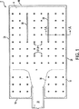
図1に、この発明の第1の実施例に従った強制空気対流システムに対する膨張可能なカバー2を示す。膨張可能なカバー2は、上側シート4および下側シート(図1には示さず)を含む。膨張可能なカバー2はたとえば、プラスチック、織物または複合繊維などの重合体でできていてもよい。 FIG. 1 shows an inflatable cover 2 for a forced air convection system according to a first embodiment of the present invention. The inflatable cover 2 includes an upper sheet 4 and a lower sheet (not shown in FIG. 1). The inflatable cover 2 may be made of a polymer such as plastic, woven fabric or composite fiber, for example.
膨張可能なカバー2は、上側端部16と、カバー2が用いられるときにたとえば患者の足の近くに位置決めするための下側端部18と、たとえば実質的に平行であってもよい2つの側部24、26とによって一般的に矩形を有し、上側シート4および下側シートの間に膨張可能な空洞を有する。
The inflatable cover 2 includes an upper end 16 and a
上側シート4および下側シートは、周辺端縁14のまわりでともに封止されることによって膨張可能なカバー2を形成する。周辺端縁14は、たとえばプラスチック溶接、熱溶接によって、または一方もしくは両方の周辺端縁14に接着剤を塗布して周辺端縁14をともに合わせることによって封止されてもよい。接着剤はたとえばエポキシなどの2液性接着剤であってもよい。 The upper sheet 4 and the lower sheet form an inflatable cover 2 by being sealed together around the peripheral edge 14. The peripheral edge 14 may be sealed, for example, by plastic welding, thermal welding, or by applying an adhesive to one or both peripheral edges 14 and bringing the peripheral edges 14 together. The adhesive may be a two-component adhesive such as an epoxy.
上側シート4および下側シートはまた、少なくとも2つの分離可能な封止線36、38に沿って、実質的に類似の態様でともに封止されてもよい。分離可能な封止線36、38はたとえば、穿孔の線、または上側シート4および下側シートの間もしくは上側シート4および下側シート内の接着剤もしくは熱もしくはプラスチック溶接によって形成されてもよく、そのたとえば剪断または引っ張りは、膨張可能なカバー2の親材料の局部的な剪断または引っ張り強さに比べて弱い。 The upper sheet 4 and the lower sheet may also be sealed together in a substantially similar manner along at least two separable sealing lines 36,38. The separable sealing lines 36, 38 may be formed, for example, by a line of perforations or an adhesive or heat or plastic welding between the upper sheet 4 and the lower sheet or in the upper sheet 4 and the lower sheet, For example, the shearing or pulling is weak compared to the local shearing or pulling strength of the parent material of the inflatable cover 2.
上側シート4および下側シートはまた、スポット溶接37および溶接線39において、周辺端縁14と実質的に類似の態様でともに封止されてもよい。溶接線39はたとえば、患者の足の領域のまわりでカバーに入る膨張媒質の流れを誘導することにより、患者の足のまわりの膨張媒質の流れを限定してもよい。好ましい実施例において、溶接線39は周辺端縁14から約2インチまたは5.08センチメートルのところで終わっており、残された間隙を通って膨張媒質の限定された量が患者の足に近接するカバー2の領域に流れ込んでもよい。 Upper sheet 4 and lower sheet may also be sealed together in a manner substantially similar to peripheral edge 14 at spot weld 37 and weld line 39. The weld line 39 may limit the flow of inflation medium around the patient's foot, for example, by inducing a flow of inflation medium that enters the cover around the area of the patient's foot. In the preferred embodiment, the weld line 39 ends approximately 2 inches or 5.08 centimeters from the peripheral edge 14 and a limited amount of inflation medium is proximate to the patient's foot through the remaining gap. It may flow into the area of the cover 2.
膨張可能なカバー2は、膨張空洞に通じる膨張ポート30をさらに含む。溶接線39はたとえば、膨張ポートに通じる膨張可能な空洞内に中央の空気通路を形成してもよい。
The inflatable cover 2 further includes an
図1Aに、膨張可能なカバー2のスポット溶接37を通る部分断面1A−1Aが示される。図1Aにおいて、上側シート4および下側シート8はスポット溶接37においてともに封止される。下側シート8は穿孔12によって穿孔されてもよい。 FIG. 1A shows a partial cross section 1A-1A through a spot weld 37 of the inflatable cover 2. In FIG. 1A, the upper sheet 4 and the lower sheet 8 are sealed together in spot welding 37. The lower sheet 8 may be perforated by perforations 12.
図2に、この発明の第2の実施例に従った強制空気対流システムに対する膨張可能なカ
バー102が示される。膨張可能なカバー102は、第1の材料106の上側シート104と、第2の材料110の下側シート108とを含む。第1および第2の材料106、108はたとえば、プラスチック、織物、または複合繊維などの重合体であってもよい。第1および第2の材料106、108は同じ材料であっても、異なる材料であってもよい。
2, inflatable mosquitoes for forced air convection system according to a second embodiment of the present invention
上側シート104および下側シート108は、周辺端縁114のまわりでともに封止されて膨張可能なカバー102を形成する。上側および下側シート104、108は、たとえばプラスチック溶接、熱溶接によって、または一方もしくは両方の周辺端縁114に接着剤を塗布して周辺端縁114をともに合わせることによって封止されてもよい。接着剤はたとえばエポキシなどの2液性接着剤であってもよい。上側シート104および下側シート108はまた、少なくとも2つの分離可能な封止線136、138に沿って、実質的に類似の態様でともに封止されてもよい。分離可能な封止線136、138はたとえば、穿孔の線、または上側および下側シート104、108の間もしくは上側および下側シート104、108内の接着剤もしくは熱もしくはプラスチック溶接によって形成されてもよく、そのたとえば剪断または引っ張りは、親の第1または第2の材料106、108の局部的な剪断または引っ張り強さに比べて弱い。
The
例示される実施例において、膨張可能なカバー102は、上側端部116と、カバー102が用いられるときに患者122のたとえば足120の近くに位置決めするための下側端部118と、たとえば実質的に平行であってもよい2つの側部124、126とによって一般的に矩形を有し、上側および下側シート104、108の間に膨張可能な空洞128を有する。
In the illustrated embodiment, the
膨張可能なカバー102の下側端部118に位置する膨張ポート130は膨張可能な空洞128を大気132に接続し、それを通じて膨張媒質134が膨張可能な空洞128に導入されてカバー102を膨張させてもよい。下側シート108の少なくとも一部は穿孔112を通じた通気性がある。穿孔112はたとえば小さな孔またはスリットであってもよい。穿孔112の大きさまたは集合流領域が、たとえばカバー102への膨張媒質134の流れの速度に合わせられることによって、カバー102は使用の際に膨張したままであるが破裂しないようにされてもよい。
An
膨張媒質134はたとえば、酸素、水蒸気、窒素、およびアルゴンなどの微量元素の組合せなどの空気、またはN2などの不活性ガスであってもよい。膨張媒質134は、たと
えば、膨張可能な空洞128に膨張媒質134をポンプ注入すること、膨張ポート130と穿孔112またはあらゆる代替的な出口との間に膨張可能な空洞128にわたる圧力差を適用すること、またはカバー102の周囲のある部分を排気することによって、膨張可能な空洞128に導入されてもよい。好ましい実施例において、膨張媒質134は加熱されてもよい。熱はまた、たとえば前述の膨張可能な空洞128にわたる圧力差の少なくともいくらかを提供し得る。
図3に示されるとおり、分離可能な封止線236、238は分離されて、カバー202を実質的に収縮させることなくスリット240、242を形成してもよい。カバー202が用いられる患者の所望の領域への接近が、スリット240、242を通じて提供される。スリット240、242は、たとえば静脈摂取手術の後に、たとえば患者の大腿部への接近を提供してもよい。スリット240、242は下側端部218に対向するカバー202の上側半分244に位置し、スリット240、242は上側端部216、側部224、226、または下側端部218とは間隔を置かれてそれらと交差しない。スリット240、242は、たとえば互いに、またはカバー202の側部224、226と実質的に平行であってもよい。好ましい実施例において、スリット240、242は破り開けるスリットであってもよい。
As shown in FIG. 3, the
図4に示される膨張可能なカバー302の第3の実施例において、基端部346を有するホース344が、膨張ポート330を滅菌野350の外側に位置する末端部348に接続してもよい。ホース344は、たとえば給気ホースまたはプラスチック管であってもよい。滅菌野350はたとえば、患者322の健康または回復に有害であるおそれのある、細菌、有機体、ウィルス、悪質なものおよび腐敗、またはその他の実体、生物もしくは無生物を実質的に処理し、除去し、またはその他の態様で無害にする努力が払われた、患者322のまわりの領域であってもよい。
In the third embodiment of the
膨張可能なカバー302は末端部348を通じて膨張されることにより、入来する膨張媒質334によって滅菌野350が損なわれないようにしてもよい。すなわち、膨張媒質334は、滅菌野350に実質的に接触または汚染することなく、末端部348においてホース344に入り、ホース344を通って基端部344に移動してもよい。実施例の1つにおいて、末端部はノズル352を有してもよい。ノズル352はたとえば「急速切断」変形のコネクタであってもよい。ノズル352はさらに、膨張媒質334の流れの速度を制御または限定するための制限を含んでもよい。図5に示される好ましい実施例においては、ホース344の上に滅菌野350aを延在させるために、ノズル352の上にシールド354が置かれる。シールド354は、たとえばプラスチック、ゴム、複合物、または繊維マットなどでできた、たとえば管状または半管状の被覆であってもよい。
The
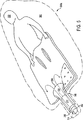
図6に示される第4の実施例において、膨張可能なカバー402は、患者422の足420に近接する膨張媒質434の流れ458を減少させるためのスロットル456を有する。たとえば膨張媒質が足420の温度を上昇または下降させる効果を有するときには、足420に対して局部的に膨張媒質434の流れ458を限定しながら、膨張可能なカバー402の残りにおいては膨張媒質434を実質的に自由に循環させることによって、足420の温度を快適なレベルに維持することが望ましくてもよい。よってスロットル456は、足420に近接するカバー402の領域における「厚み」を、カバー402の残りに比べて減少させてもよい。スロットル456は、たとえばバッフル、制限、または溶接線もしくは封止領域などのくびれであってもよい。好ましい実施例において、スロットル456は周辺端縁414から約2インチまたは5.08センチメートルのところで終わる。スロットル456はさらに、たとえば制御可能な制限であることによって、膨張媒質434の流れ458の速度の範囲が足420に局部的に適用されてもよい。
In the fourth example shown in FIG. 6, the inflatable cover 402 has a throttle 456 to reduce the
図7に示される第5の実施例において、膨張可能なカバー502は、膨張媒質がカバー502に導入される前にカバー502のまわりに配される小袋558の中に入っている。よって、膨張可能なカバー502は小袋558が開けられる前に滅菌野の中に提供され得る。好ましい実施例において、小袋558は破り開ける開口部560を有する。破り開ける開口部560はたとえば、穿孔の線、または小袋558の側部の間の接着剤もしくは熱もしくはプラスチック溶接によって生成されてもよく、そのたとえば剪断または引っ張りは、小袋558の親材料の局部的な剪断または引っ張り強さに比べて弱い。
In the fifth embodiment shown in FIG. 7, the inflatable cover 502 is contained within the
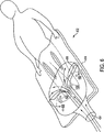
図8に示される第6の実施例において、膨張可能なカバー602は、カバー602に膨張媒質が導入される前にカバー602を開いて患者622の腹部664の上に置くことを可能にする折り目662を有する。好ましい実施例において、カバー602は滅菌野650を汚染することなく下方に開く。
In the sixth embodiment shown in FIG. 8, the
膨張可能なカバー602は、折り畳まれた状態のカバーが入った小袋558を破り開け、小袋658からカバー602を取出し、折り畳まれた状態のカバー602を患者622の上に置き、カバー602を下および外側に開き、カバー602を膨張させることによって用いられてもよい。
この発明について上に詳細に説明したが、この発明が記載される特定の実施例に限定されることは意図されない。当業者は、この発明の概念から逸脱することなく、ここに説明される特定の実施例の多数の使用および変更および逸脱を行なってもよいことが明らかである。 Although the invention has been described in detail above, it is not intended that the invention be limited to the specific embodiments described. It will be apparent to those skilled in the art that numerous uses and modifications and departures from the specific embodiments described herein may be made without departing from the inventive concept.
Claims (6)
材料の上側シートと、
材料の下側シートとを含み、前記下側シートの少なくとも一部は通気性があり、
前記上側シートおよび前記下側シートはその周縁端縁のまわりでともに封止されることによって、上側端部と、前記カバーが用いられるときに患者の足の近くに位置決めするための下側端部と、2つの実質的に平行な側部とを有し、かつ上側および下側シートの間に膨張可能な空洞を有する膨張可能なカバーを形成し、
膨張可能なカバーの下側端部に位置する膨張ポートは前記膨張可能な空洞を大気に接続し、前記膨張ポートを通じて前記膨張可能な空洞に空気が導入されることによって前記カバーを膨張させてもよく、
前記上側シートおよび前記下側シートは少なくとも2つの分離可能な封止線に沿ってともにさらに封止されることによって、前記分離可能な封止線の少なくとも1つが分離されてスリットを形成するときに,前記カバーが用いられている患者の大腿部の動脈へのカバーを通じた接近が前記スリットを通じて提供され、前記分離可能な封止線は前記下側端部に対向する前記カバーの上側半分に位置し、前記分離可能な封止線は前記上側端部、前記側部および前記下側端部とは間隔を置かれて交差せず、前記分離可能な封止線は互いにおよび前記カバーの前記側部と実質的に平行であり、
前記膨張ポートは膨張可能なカバーの下側端部から離れて外向きに延在し、前記上側シートおよび前記下側シートの伸長部の周辺部を封止することによって形成され、前記伸長部は前記膨張可能なカバーの前記下側端部から外向きに延在する、膨張可能なカバー。An inflatable cover for a forced air convection system, which cover is used in cardiac surgery;
An upper sheet of material;
A lower sheet of material, at least a portion of the lower sheet being breathable,
The upper sheet and the lower sheet are sealed together around their peripheral edges so that the upper edge and the lower edge for positioning near the patient's foot when the cover is used And forming an inflatable cover having two substantially parallel sides and having an inflatable cavity between the upper and lower sheets,
An inflation port located at the lower end of the inflatable cover connects the inflatable cavity to the atmosphere, and air is introduced into the inflatable cavity through the inflation port to inflate the cover. Often,
When the upper sheet and the lower sheet are further sealed together along at least two separable sealing lines, when at least one of the separable sealing lines is separated to form a slit , Access through the cover to the artery of the patient's thigh where the cover is used is provided through the slit, and the separable sealing line is in the upper half of the cover opposite the lower end. The separable sealing lines are spaced apart from the upper end, the side and the lower end, and the separable sealing lines are separated from each other and the cover Ri sides substantially parallel der,
The expansion port extends outwardly away from the lower end of the inflatable cover, and is formed by sealing the periphery of the upper sheet and the extension of the lower sheet, the extension being An inflatable cover extending outwardly from the lower end of the inflatable cover .
なくとも一部を覆い、前記膨張ポートに前記給気ホースが接続されるときに前記給気ホースの少なくとも一部を覆うために、カバーに取付けられて前記膨張ポートの外表面のまわりに位置決めされる管状の被覆をさらに含む、請求項1または2に記載の膨張可能なカバー。The expansion port is tubular and the inflatable cover covers at least a portion of the outer surface of the expansion port, and at least a portion of the air supply hose when the air supply hose is connected to the expansion port to the cover, further comprising a coating of tubular attached to the cover is positioned around the outer surface of said inflation port, expandable cover according to claim 1 or 2.
材料の上側シートと、
材料の下側シートとを含み、前記下側シートの少なくとも一部は通気性があり、
前記上側シートおよび前記下側シートはその周縁端縁のまわりでともに封止されることによって、上側端部と、前記カバーが用いられるときに患者の足の近くに位置決めするための下側端部と、2つの側部とを有し、かつ上側および下側シートの間に膨張可能な空洞を有する膨張可能なカバーを形成し、
前記上側シートおよび前記下側シートは少なくとも2つの分離可能な封止線に沿ってともにさらに封止されることによって、前記分離可能な封止線の少なくとも1つが分離されてスリットを形成するときに,前記カバーが用いられている患者の大腿部の動脈へのカバーを通じた接近が前記スリットを通じて提供され、前記分離可能な封止線は前記下側端部に対向する前記カバーの上側半分に位置し、前記分離可能な封止線は前記上側端部、前記側部および前記下側端部とは間隔を置かれて交差せず、前記分離可能な封止線は互いにおよび前記カバーの前記側部と実質的に平行であり、
膨張可能なカバーの下側端部に位置する膨張ポートは前記膨張可能な空洞を大気に接続し、前記膨張ポートを通じて前記膨張可能な空洞に空気が導入されることによって前記カバーを膨張させてもよく、
前記膨張ポートは膨張可能なカバーの下側端部から離れて外向きに延在し、前記上側シートおよび前記下側シートの伸長部の周辺部を封止することによって形成され、前記伸長部は前記膨張可能なカバーの前記下側端部から外向きに延在し、
前記膨張ポートは給気ホースに接続可能であり、前記給気ホースを通じて前記膨張可能な空洞に前記空気が導入されて前記カバーを膨張させてもよく、前記膨張ポートは前記上側シートおよび前記下側シートの周辺部を封止することによって前記上側シートおよび前記下側シートの間に形成されることによって、前記膨張可能な空洞に通じる前記膨張ポート内に中央の空気通路を形成し、
前記膨張ポートは管状であり、前記膨張可能なカバーは、前記膨張ポートの外表面の少なくとも一部を覆い、前記膨張ポートに前記給気ホースが接続されるときに前記給気ホースの少なくとも一部を覆うために、カバーに取付けられて前記膨張ポートの外表面のまわりに位置決めされる管状の被覆をさらに含む、膨張可能なカバー機器。An inflatable cover device with forced air convection, which is used in cardiac surgery,
An upper sheet of material;
A lower sheet of material, at least a portion of the lower sheet being breathable,
The upper sheet and the lower sheet are sealed together around their peripheral edges so that the upper edge and the lower edge for positioning near the patient's foot when the cover is used And an inflatable cover having two sides and having an inflatable cavity between the upper and lower sheets,
When the upper sheet and the lower sheet are further sealed together along at least two separable sealing lines, when at least one of the separable sealing lines is separated to form a slit , Access through the cover to the artery of the patient's thigh where the cover is used is provided through the slit, and the separable sealing line is in the upper half of the cover opposite the lower end. The separable sealing lines are spaced apart from the upper end, the side and the lower end, and the separable sealing lines are separated from each other and the cover Substantially parallel to the sides,
An inflation port located at the lower end of the inflatable cover connects the inflatable cavity to the atmosphere, and air is introduced into the inflatable cavity through the inflation port to inflate the cover. Often,
The expansion port extends outwardly away from the lower end of the inflatable cover, and is formed by sealing the periphery of the upper sheet and the extension of the lower sheet, the extension being Extending outwardly from the lower end of the inflatable cover,
The expansion port may be connected to an air supply hose, and the air may be introduced into the expandable cavity through the air supply hose to expand the cover, and the expansion port may include the upper seat and the lower side. Forming a central air passage in the expansion port leading to the inflatable cavity by being formed between the upper sheet and the lower sheet by sealing the periphery of the sheet;
The expansion port is tubular and the inflatable cover covers at least a portion of the outer surface of the expansion port, and at least a portion of the air supply hose when the air supply hose is connected to the expansion port An inflatable cover device further comprising a tubular covering attached to the cover and positioned about an outer surface of the inflation port to cover the cover .
材料の上側シートと、
材料の下側シートとを含み、前記下側シートの少なくとも一部は通気性があり、
前記上側シートおよび前記下側シートはその周縁端縁のまわりでともに封止されることによって、上側端部と、前記カバーが用いられるときに患者の足の近くに位置決めするための下側端部と、2つの実質的に平行な側部とを有し、かつ上側および下側シートの間に膨張可能な空洞を有する膨張可能なカバーを形成し、
前記上側シートおよび前記下側シートは少なくとも2つの分離可能な封止線に沿ってともにさらに封止されることによって、前記分離可能な封止線の少なくとも1つが分離されてスリットを形成するときに,前記カバーが用いられている患者の大腿部の動脈へのカバーを通じた接近が前記スリットを通じて提供され、前記分離可能な封止線は前記下側端部に対向する前記カバーの上側半分に位置し、前記分離可能な封止線は前記上側端部、前記側部および前記下側端部とは間隔を置かれて交差せず、前記分離可能な封止線は互いにおよび前記カバーの前記側部と実質的に平行であり、
膨張可能なカバーの下側端部に位置する膨張ポートは前記膨張可能な空洞を大気に接続し、前記膨張ポートを通じて前記膨張可能な空洞に空気が導入されることによって前記カバーを膨張させてもよく、
前記膨張ポートは膨張可能なカバーの下側端部から離れて外向きに延在し、前記上側シートおよび前記下側シートの伸長部の周辺部を封止することによって形成され、前記伸長部は前記膨張可能なカバーの前記下側端部から外向きに延在し、
カバーの下側端部に近接する足を覆う領域を提供するためにカバーの下側端部における上側シートおよび下側シートの間に封止領域が設けられ、前記封止領域は前記膨張可能なカバーの前記足を覆う領域への空気の通過を減少させる、膨張可能なカバー機器。An inflatable cover device using forced air convection, which is used in cardiac surgery,
An upper sheet of material;
A lower sheet of material, at least a portion of the lower sheet being breathable,
The upper sheet and the lower sheet are sealed together around their peripheral edges so that the upper edge and the lower edge for positioning near the patient's foot when the cover is used And forming an inflatable cover having two substantially parallel sides and having an inflatable cavity between the upper and lower sheets,
When the upper sheet and the lower sheet are further sealed together along at least two separable sealing lines, when at least one of the separable sealing lines is separated to form a slit , Access through the cover to the artery of the patient's thigh where the cover is used is provided through the slit, and the separable sealing line is in the upper half of the cover opposite the lower end. The separable sealing lines are spaced apart from the upper end, the side and the lower end, and the separable sealing lines are separated from each other and the cover Substantially parallel to the sides,
An inflation port located at the lower end of the inflatable cover connects the inflatable cavity to the atmosphere, and air is introduced into the inflatable cavity through the inflation port to inflate the cover. Often,
The expansion port extends outwardly away from the lower end of the inflatable cover, and is formed by sealing the periphery of the upper sheet and the extension of the lower sheet, the extension being Extending outwardly from the lower end of the inflatable cover,
A sealing region is provided between the upper sheet and the lower sheet at the lower end of the cover to provide a region covering the foot proximate the lower end of the cover , the sealing region being inflatable An inflatable cover device that reduces the passage of air to the area of the cover covering the foot.
Applications Claiming Priority (2)
| Application Number | Priority Date | Filing Date | Title |
|---|---|---|---|
| US34867102P | 2002-01-17 | 2002-01-17 | |
| PCT/US2003/000818 WO2003061534A2 (en) | 2002-01-17 | 2003-01-13 | Inflatable blanket for use in cardiac surgery |
Publications (3)
| Publication Number | Publication Date |
|---|---|
| JP2005515025A JP2005515025A (en) | 2005-05-26 |
| JP2005515025A5 JP2005515025A5 (en) | 2005-12-22 |
| JP4346445B2 true JP4346445B2 (en) | 2009-10-21 |
Family
ID=27613236
Family Applications (1)
| Application Number | Title | Priority Date | Filing Date |
|---|---|---|---|
| JP2003561480A Expired - Fee Related JP4346445B2 (en) | 2002-01-17 | 2003-01-13 | Inflatable cover for use in cardiac surgery |
Country Status (8)
| Country | Link |
|---|---|
| US (2) | US7172616B2 (en) |
| EP (2) | EP1467685B1 (en) |
| JP (1) | JP4346445B2 (en) |
| AT (1) | ATE492252T1 (en) |
| CA (1) | CA2472722C (en) |
| DE (1) | DE60335446D1 (en) |
| ES (1) | ES2356812T3 (en) |
| WO (1) | WO2003061534A2 (en) |
Families Citing this family (15)
| Publication number | Priority date | Publication date | Assignee | Title |
|---|---|---|---|---|
| US8470012B2 (en) | 2004-09-08 | 2013-06-25 | Arizant Healthcare Inc. | Inflatable convective pad for surgery |
| US20060231683A1 (en) * | 2005-04-18 | 2006-10-19 | Orr James R | Aircraft & motor vehicle protection system that eliminates eleven safety and environmental hazards associated with aircraft and vehicles parked or tied down and exposed to the elements and animals |
| US20100106229A1 (en) * | 2006-09-08 | 2010-04-29 | Adroit Medical Systems, Inc. | Thermal skull pads for coolant system |
| US7901443B2 (en) * | 2006-09-27 | 2011-03-08 | Nellcor Puritan Bennett Llc | Method and apparatus for inflating a warming blanket |
| US7879078B2 (en) * | 2006-09-27 | 2011-02-01 | Nellcor Puritan Bennett Llc | Use of convective air warming system for patient care |
| US7905911B2 (en) * | 2006-09-27 | 2011-03-15 | Nellcor Puritan Bennett Llc | Method and apparatus for connecting a hose to a warming blanket |
| US20100198320A1 (en) * | 2009-01-30 | 2010-08-05 | Smiths Medical Asd, Inc. | Lateral access blanket |
| US8197525B2 (en) * | 2009-02-13 | 2012-06-12 | Smiths Medical Asd, Inc. | Full body split access blanket |
| US8177828B2 (en) * | 2009-07-27 | 2012-05-15 | Arizant Healthcare Inc. | Underbody convective warming blanket constructions |
| US11395759B2 (en) | 2014-08-18 | 2022-07-26 | Medline Industries, Lp | Method and apparatus pertaining to securement of a personal patient warming apparatus |
| EP3236896A1 (en) * | 2014-12-23 | 2017-11-01 | 3M Innovative Properties Company | Flexible duct for convective device |
| US10441006B2 (en) * | 2015-12-07 | 2019-10-15 | Medline Industries, Inc. | Patient-warming gown |
| US11234860B2 (en) | 2016-10-21 | 2022-02-01 | 3M Innovative Properties Company | Multi-sectional patient warming blanket |
| WO2018075579A1 (en) * | 2016-10-21 | 2018-04-26 | 3M Innovative Properties Company | Low-profile forced-air blanket |
| WO2023111328A1 (en) | 2021-12-17 | 2023-06-22 | The Surgical Company International B.V. | A forced air warming device |
Family Cites Families (50)
| Publication number | Priority date | Publication date | Assignee | Title |
|---|---|---|---|---|
| US1320967A (en) | 1919-11-04 | battles | ||
| US1356967A (en) | 1918-08-05 | 1920-10-26 | Carbo Gas Company Inc | Decarbonizer |
| GB528376A (en) * | 1939-04-26 | 1940-10-29 | Hans Frankmann | Improvements in and relating to hot-water bottles and like containers made of flexible material |
| US2512559A (en) | 1945-01-18 | 1950-06-20 | Alfred L W Williams | Comfort unit |
| US2930594A (en) * | 1954-06-25 | 1960-03-29 | Jet Heet Inc | Personal thermal devices |
| US3215418A (en) * | 1961-10-13 | 1965-11-02 | Hupp Corp | Heating apparatus |
| US3444922A (en) | 1966-12-06 | 1969-05-20 | Edward H Dingman | Apparatus for passing flowing air about a bed occupant at selective temperatures |
| US4094357A (en) | 1976-04-09 | 1978-06-13 | Kenneth C. McCord | Heat transfer blanket |
| US4114620A (en) | 1977-03-02 | 1978-09-19 | Moore-Perk Corporation | Patient treatment pad for hot or cold use |
| US4628931A (en) * | 1982-03-03 | 1986-12-16 | Barrett Harold F | Medical treatment method |
| US4572188A (en) | 1984-03-05 | 1986-02-25 | Augustine Scott D | Airflow cover for controlling body temperature |
| US4660388A (en) | 1984-05-24 | 1987-04-28 | Greene Jr George J | Cooling cover |
| ES2029888T3 (en) | 1987-10-05 | 1992-10-01 | Augustine Medical, Inc. | A THERMAL COVER. |
| US5405371A (en) | 1987-10-05 | 1995-04-11 | Augustine Medical, Inc. | Thermal blanket |
| US5300102A (en) | 1987-10-05 | 1994-04-05 | Augustine Medical, Inc. | Thermal blanket |
| US5184612A (en) | 1987-10-05 | 1993-02-09 | Augustine Medical, Inc. | Thermal blanket with transparent upper body drape |
| US5300100A (en) | 1990-08-22 | 1994-04-05 | Advanced Warming Systems, Inc. | Body warmer |
| US5330519B1 (en) * | 1990-09-05 | 1998-11-10 | Breg Inc | Therapeutic nonambient temperature fluid circulation system |
| US5241951B1 (en) * | 1990-09-05 | 1999-07-06 | Breg Inc | Therapeutic nonambient temperature fluid circulation system |
| US5125238A (en) | 1991-04-29 | 1992-06-30 | Progressive Dynamics, Inc. | Patient warming or cooling blanket |
| US5405370A (en) | 1991-11-08 | 1995-04-11 | Irani; Feraidoon | Air blanket |
| US5264599A (en) | 1991-11-08 | 1993-11-23 | Iowa State University Research Foundation | Process for reducing cholesterol in animal fats |
| US5318568A (en) | 1991-11-15 | 1994-06-07 | Advanced Warming Systems, Inc. | Inflatable blanket and nozzle therefor |
| US5165127A (en) | 1992-01-23 | 1992-11-24 | Barry Nicholson | Heating and cooling blanket apparatus |
| US5265599A (en) * | 1992-10-01 | 1993-11-30 | Progressive Dynamics, Inc. | Patient temperature control blanket with controlled air distribution |
| US5350417A (en) | 1993-05-18 | 1994-09-27 | Augustine Medical, Inc. | Convective thermal blanket |
| US5304213A (en) | 1993-06-14 | 1994-04-19 | Cincinnati Sub-Zero Products, Inc. | Hyper-hypothermia blanket with filtration properties |
| US5470353A (en) | 1993-10-20 | 1995-11-28 | Hollister Incorporated | Post-operative thermal blanket |
| US5392847A (en) | 1993-11-29 | 1995-02-28 | Progressive Dynamics, Inc. | Thermal medical blanket using internal subtube |
| US5443488A (en) | 1994-08-15 | 1995-08-22 | Progressive Dynamics, Inc. | Thermal blanket with surgical access |
| US5964792A (en) | 1996-08-02 | 1999-10-12 | Augustine Medical, Inc. | Convertible thermal blanket |
| US5545194A (en) | 1994-09-30 | 1996-08-13 | Augustine Medical, Inc. | Convertible thermal blanket |
| ATE236592T1 (en) | 1994-11-23 | 2003-04-15 | Mallinckrodt Inc | INFLATABLE CEILING WITH MOLDED OPENINGS |
| US5674269A (en) | 1995-02-06 | 1997-10-07 | Augustine Medical, Inc. | Patient warming system with user-configurable access panel |
| US5735890A (en) * | 1995-10-18 | 1998-04-07 | Mallinckrodt Medical, Inc. | Inflatable blanket having access slits |
| US5697963A (en) | 1995-12-20 | 1997-12-16 | Augustine Medical, Inc. | Thermal blanket for a patient sitting in a chair |
| US5991666A (en) | 1996-03-21 | 1999-11-23 | Microtek Medical, Inc. | Sterile surgical-thermal draping system and method |
| US5997572A (en) | 1996-03-29 | 1999-12-07 | Augustine Medical, Inc. | Inlet port plug for inflatable thermal blankets |
| US5785716A (en) | 1996-05-09 | 1998-07-28 | Bayron; Harry | Temperature control pad for use during medical and surgical procedures |
| US5728145A (en) | 1996-07-22 | 1998-03-17 | Progressive Dynamics, Inc. | Thermal blanket with central air inlet |
| US5966763A (en) | 1996-08-02 | 1999-10-19 | Hill-Rom, Inc. | Surface pad system for a surgical table |
| US5720774A (en) | 1996-10-28 | 1998-02-24 | Appliance Development Corp. | Heating pad |
| US5941907A (en) | 1997-06-02 | 1999-08-24 | Augustine Medical, Inc. | Surgical barrier device incorporating an inflatable thermal blanket with a surgical drape to provide thermal control and surgical access |
| US6176870B1 (en) | 1997-08-13 | 2001-01-23 | Augustine Medical, Inc. | Inflatable thermal blanket with surgical access for use with patients in the lithotomy position |
| US5824025A (en) | 1997-08-20 | 1998-10-20 | Augustine Medical, Inc. | System for convective warming of a patient during cardiac surgery |
| US5860292A (en) | 1997-08-26 | 1999-01-19 | Augustine Medical, Inc. | Inflatable thermal blanket for convectively cooling a body |
| EP1028684B1 (en) | 1997-11-07 | 2004-03-03 | Hill-Rom Services, Inc. | Medical equipment controller |
| US6102936A (en) * | 1998-07-21 | 2000-08-15 | Augustine Medical, Inc. | Inflatable thermal pad with drainage |
| US6126681A (en) | 1998-08-24 | 2000-10-03 | Augustine Medical, Inc. | Detection of a condition between an inflatable thermal device and an air hose in a convective warming system |
| US6168612B1 (en) | 1999-03-26 | 2001-01-02 | Augustine Medical, Inc. | Inflatable thermal blanket with a multilayer sheet |
-
2002
- 2002-12-19 US US10/322,388 patent/US7172616B2/en not_active Expired - Lifetime
-
2003
- 2003-01-13 EP EP03707356A patent/EP1467685B1/en not_active Expired - Lifetime
- 2003-01-13 JP JP2003561480A patent/JP4346445B2/en not_active Expired - Fee Related
- 2003-01-13 CA CA2472722A patent/CA2472722C/en not_active Expired - Fee Related
- 2003-01-13 WO PCT/US2003/000818 patent/WO2003061534A2/en active Search and Examination
- 2003-01-13 AT AT03707356T patent/ATE492252T1/en not_active IP Right Cessation
- 2003-01-13 EP EP10075282.3A patent/EP2236108B1/en not_active Expired - Lifetime
- 2003-01-13 ES ES03707356T patent/ES2356812T3/en not_active Expired - Lifetime
- 2003-01-13 DE DE60335446T patent/DE60335446D1/en not_active Expired - Lifetime
-
2007
- 2007-01-16 US US11/654,351 patent/US7951184B2/en active Active
Also Published As
| Publication number | Publication date |
|---|---|
| EP1467685B1 (en) | 2010-12-22 |
| ATE492252T1 (en) | 2011-01-15 |
| EP2236108A2 (en) | 2010-10-06 |
| US20070118195A1 (en) | 2007-05-24 |
| EP2236108A3 (en) | 2011-01-19 |
| DE60335446D1 (en) | 2011-02-03 |
| EP2236108B1 (en) | 2016-07-13 |
| US7951184B2 (en) | 2011-05-31 |
| EP1467685A2 (en) | 2004-10-20 |
| US20030135251A1 (en) | 2003-07-17 |
| WO2003061534A2 (en) | 2003-07-31 |
| ES2356812T3 (en) | 2011-04-13 |
| CA2472722C (en) | 2011-05-31 |
| US7172616B2 (en) | 2007-02-06 |
| WO2003061534A3 (en) | 2004-03-18 |
| JP2005515025A (en) | 2005-05-26 |
| CA2472722A1 (en) | 2003-07-31 |
Similar Documents
| Publication | Publication Date | Title |
|---|---|---|
| US7951184B2 (en) | Inflatable blanket for use in cardiac surgery | |
| US6102936A (en) | Inflatable thermal pad with drainage | |
| US7871428B2 (en) | Surgical barrier device incorporating an inflatable thermal blanket with an attached surgical drape | |
| US5304213A (en) | Hyper-hypothermia blanket with filtration properties | |
| EP0766543B1 (en) | Upper body warming blanket | |
| US6176870B1 (en) | Inflatable thermal blanket with surgical access for use with patients in the lithotomy position | |
| EP2893910B1 (en) | Forced air warming blanket | |
| US20140277307A1 (en) | Companion animal convective air blankets | |
| US6994720B2 (en) | Inflatable thermal blanket with sterile access | |
| US8177828B2 (en) | Underbody convective warming blanket constructions |
Legal Events
| Date | Code | Title | Description |
|---|---|---|---|
| A621 | Written request for application examination |
Free format text: JAPANESE INTERMEDIATE CODE: A621 Effective date: 20060106 |
|
| A131 | Notification of reasons for refusal |
Free format text: JAPANESE INTERMEDIATE CODE: A131 Effective date: 20090210 |
|
| A601 | Written request for extension of time |
Free format text: JAPANESE INTERMEDIATE CODE: A601 Effective date: 20090508 |
|
| A521 | Request for written amendment filed |
Free format text: JAPANESE INTERMEDIATE CODE: A523 Effective date: 20090515 |
|
| A602 | Written permission of extension of time |
Free format text: JAPANESE INTERMEDIATE CODE: A602 Effective date: 20090515 |
|
| TRDD | Decision of grant or rejection written | ||
| A01 | Written decision to grant a patent or to grant a registration (utility model) |
Free format text: JAPANESE INTERMEDIATE CODE: A01 Effective date: 20090616 |
|
| A01 | Written decision to grant a patent or to grant a registration (utility model) |
Free format text: JAPANESE INTERMEDIATE CODE: A01 |
|
| A61 | First payment of annual fees (during grant procedure) |
Free format text: JAPANESE INTERMEDIATE CODE: A61 Effective date: 20090714 |
|
| R150 | Certificate of patent or registration of utility model |
Ref document number: 4346445 Country of ref document: JP Free format text: JAPANESE INTERMEDIATE CODE: R150 Free format text: JAPANESE INTERMEDIATE CODE: R150 |
|
| FPAY | Renewal fee payment (event date is renewal date of database) |
Free format text: PAYMENT UNTIL: 20120724 Year of fee payment: 3 |
|
| FPAY | Renewal fee payment (event date is renewal date of database) |
Free format text: PAYMENT UNTIL: 20120724 Year of fee payment: 3 |
|
| RD02 | Notification of acceptance of power of attorney |
Free format text: JAPANESE INTERMEDIATE CODE: R3D02 |
|
| FPAY | Renewal fee payment (event date is renewal date of database) |
Free format text: PAYMENT UNTIL: 20120724 Year of fee payment: 3 |
|
| RD04 | Notification of resignation of power of attorney |
Free format text: JAPANESE INTERMEDIATE CODE: R3D04 |
|
| FPAY | Renewal fee payment (event date is renewal date of database) |
Free format text: PAYMENT UNTIL: 20120724 Year of fee payment: 3 |
|
| S111 | Request for change of ownership or part of ownership |
Free format text: JAPANESE INTERMEDIATE CODE: R313113 |
|
| S531 | Written request for registration of change of domicile |
Free format text: JAPANESE INTERMEDIATE CODE: R313531 |
|
| FPAY | Renewal fee payment (event date is renewal date of database) |
Free format text: PAYMENT UNTIL: 20120724 Year of fee payment: 3 |
|
| R350 | Written notification of registration of transfer |
Free format text: JAPANESE INTERMEDIATE CODE: R350 |
|
| FPAY | Renewal fee payment (event date is renewal date of database) |
Free format text: PAYMENT UNTIL: 20120724 Year of fee payment: 3 |
|
| FPAY | Renewal fee payment (event date is renewal date of database) |
Free format text: PAYMENT UNTIL: 20130724 Year of fee payment: 4 |
|
| R250 | Receipt of annual fees |
Free format text: JAPANESE INTERMEDIATE CODE: R250 |
|
| R250 | Receipt of annual fees |
Free format text: JAPANESE INTERMEDIATE CODE: R250 |
|
| R250 | Receipt of annual fees |
Free format text: JAPANESE INTERMEDIATE CODE: R250 |
|
| R250 | Receipt of annual fees |
Free format text: JAPANESE INTERMEDIATE CODE: R250 |
|
| R250 | Receipt of annual fees |
Free format text: JAPANESE INTERMEDIATE CODE: R250 |
|
| R250 | Receipt of annual fees |
Free format text: JAPANESE INTERMEDIATE CODE: R250 |
|
| R250 | Receipt of annual fees |
Free format text: JAPANESE INTERMEDIATE CODE: R250 |
|
| R250 | Receipt of annual fees |
Free format text: JAPANESE INTERMEDIATE CODE: R250 |
|
| LAPS | Cancellation because of no payment of annual fees |