JP4345515B2 - Imaging apparatus and program - Google Patents
Imaging apparatus and program Download PDFInfo
- Publication number
- JP4345515B2 JP4345515B2 JP2004036402A JP2004036402A JP4345515B2 JP 4345515 B2 JP4345515 B2 JP 4345515B2 JP 2004036402 A JP2004036402 A JP 2004036402A JP 2004036402 A JP2004036402 A JP 2004036402A JP 4345515 B2 JP4345515 B2 JP 4345515B2
- Authority
- JP
- Japan
- Prior art keywords
- moving image
- imaging
- area
- shooting
- moving
- Prior art date
- Legal status (The legal status is an assumption and is not a legal conclusion. Google has not performed a legal analysis and makes no representation as to the accuracy of the status listed.)
- Expired - Fee Related
Links
Images


Description
本発明は、例えばデジタルカメラ等の撮像装置に係り、特に静止画と動画を撮影可能な撮像装置と、この撮像装置に用いられるプログラムに関する。 The present invention relates to an imaging apparatus such as a digital camera, and more particularly to an imaging apparatus capable of capturing still images and moving images, and a program used for the imaging apparatus.
近年のデジタルカメラの普及に伴い、静止画の撮影だけでなく、動画の撮影も可能なカメラが一般的になってきた。この場合、通常、静止画と動画の撮影は個別に行われるものであるが、その両方の撮影を行う技術として、例えば特許文献1に開示されているものが知られている。
With the recent spread of digital cameras, cameras capable of shooting not only still images but also moving images have become common. In this case, the still image and the moving image are usually shot separately. However, as a technique for shooting both of them, for example, one disclosed in
前記特許文献1では、撮像素子であるCCDの全エリアを静止画用とし、その中の特定のエリアを動画用として定めておくことで、1台のカメラで静止画と動画の両方の撮影を行うことを実現している。
しかしながら、上述した特許文献1に開示されている方法では、静止画に対する動画のエリアは固定であり、予め決められた部分の動画データしか得られない。このため、動画撮影を要する部分が前記動画エリアと違う場所にある場合には対応できないなどの欠点がある。
However, in the method disclosed in
本発明は前記のような点に鑑みなされたもので、簡単な操作により、静止画の撮影と共にその静止画の中でユーザが望む部分だけを動画撮影することのできる撮像装置、プログラムを提供することを目的とする。 The present invention has been made in view of the above points, and provides an imaging apparatus and a program that can shoot a still image as well as a portion desired by a user in the still image by a simple operation. For the purpose.
本発明の第一の観点に係る撮像装置は、An imaging apparatus according to a first aspect of the present invention is:
静止画像と動画像とを撮像する撮像手段と、Imaging means for capturing still images and moving images;
前記撮像手段により撮像された画像を表示するモニタ画面と、A monitor screen for displaying an image captured by the imaging means;
ユーザの操作に基づき、前記モニタ画面内の任意の領域を、前記動画像の撮影範囲を規定する動画エリアとして設定する動画エリア設定手段と、Movie area setting means for setting an arbitrary area in the monitor screen based on a user operation as a movie area defining the shooting range of the moving image;
前記撮像手段が動画像を撮像するタイミングを設定する第1のスケジュール設定手段と、First schedule setting means for setting the timing at which the imaging means captures a moving image;
前記動画エリア設定手段により設定された動画エリアの所定の移動先の位置を設定する第2のスケジュール設定手段と、Second schedule setting means for setting a position of a predetermined moving destination of the moving image area set by the moving image area setting means;
前記撮像手段に、前記撮像手段の撮影範囲の全体において静止画像を撮像させる第1の撮像制御手段と、First imaging control means for causing the imaging means to capture a still image in the entire imaging range of the imaging means;
前記撮像手段に、前記第1のスケジュール設定手段により設定されたタイミングに従って、前記動画エリア設定手段により設定された動画エリアの初期位置から前記第2のスケジュール設定手段により設定された所定の移動先の位置まで前記動画エリアを移動させながら、前記動画エリアにより規定される撮影範囲における動画像を部分動画像として撮像させる第2の撮像制御手段と、In accordance with the timing set by the first schedule setting means, the image pickup means moves from the initial position of the moving image area set by the moving image area setting means to a predetermined destination set by the second schedule setting means. Second imaging control means for imaging a moving image in a shooting range defined by the moving image area as a partial moving image while moving the moving image area to a position;
を備えることを特徴とする。It is characterized by providing.
前記動画エリア設定手段により設定された動画エリアの第1のサイズとは異なる、前記動画エリアの第2のサイズを設定する第3のスケジュール設定手段を、さらに備え、A third schedule setting means for setting a second size of the moving image area different from the first size of the moving image area set by the moving image area setting means;
前記第2の撮像制御手段は、The second imaging control means includes:
前記撮像手段に、前記第1のスケジュール設定手段により設定されたタイミングに従って、前記第3のスケジュール設定手段により設定された第2のサイズまで前記動画エリアのサイズを変更させながら、前記部分動画像を撮像させるWhile causing the imaging unit to change the size of the moving image area to the second size set by the third schedule setting unit according to the timing set by the first schedule setting unit, the partial moving image is displayed. Image
ようにしてもよい。You may do it.
前記動画エリア設定手段は、The moving image area setting means includes:
ユーザの操作に基づき、前記モニタ画面内の任意の複数の領域を、複数の動画エリアとして設定し、Based on the user's operation, set a plurality of arbitrary areas in the monitor screen as a plurality of moving image areas,
前記第1のスケジュール設定手段は、The first schedule setting means includes:
前記撮像手段が、前記複数の動画エリアによりそれぞれ規定される複数の撮影範囲における動画像を撮像するタイミングをそれぞれ設定し、The imaging means sets timings for capturing moving images in a plurality of shooting ranges respectively defined by the plurality of moving image areas,
前記第2の撮像制御手段は、The second imaging control means includes:
前記撮像手段に、前記第1のスケジュール設定手段により設定されたタイミングに従って、前記複数の動画エリアにより規定される複数の撮影範囲における動画像を、複数の前記部分動画像としてそれぞれ撮像させるThe imaging unit causes the moving images in the plurality of shooting ranges defined by the plurality of moving image areas to be respectively captured as the plurality of partial moving images according to the timing set by the first schedule setting unit.
ようにしてもよい。You may do it.
本発明の第二の観点に係るプログラムは、The program according to the second aspect of the present invention is:
静止画像と動画像とを撮像する撮像手段と、前記撮像手段により撮像された画像を表示するモニタ画面と、を備える撮像装置のコンピュータを、An imaging device comprising: an imaging unit that captures a still image and a moving image; and a monitor screen that displays an image captured by the imaging unit;
ユーザの操作に基づき、前記モニタ画面内の任意の領域を、前記動画像の撮影範囲を規定する動画エリアとして設定する動画エリア設定手段、Movie area setting means for setting an arbitrary area in the monitor screen as a movie area defining the shooting range of the moving image based on a user operation;
前記撮像手段が動画像を撮像するタイミングを設定する第1のスケジュール設定手段、First schedule setting means for setting a timing at which the imaging means captures a moving image;
前記動画エリア設定手段により設定された動画エリアの所定の移動先の位置を設定する第2のスケジュール設定手段と、Second schedule setting means for setting a position of a predetermined moving destination of the moving image area set by the moving image area setting means;
前記撮像手段に、前記撮像手段の撮影範囲の全体において静止画像を撮像させる第1の撮像制御手段、First imaging control means for causing the imaging means to capture a still image in the entire imaging range of the imaging means;
前記撮像手段に、前記第1のスケジュール設定手段により設定されたタイミングに従って、前記動画エリア設定手段により設定された動画エリアの初期位置から前記第2のスケジュール設定手段により設定された所定の移動先の位置まで前記動画エリアを移動させながら、前記動画エリアにより規定される撮影範囲における動画像を部分動画像として撮像させる第2の撮像制御手段、In accordance with the timing set by the first schedule setting means, the image pickup means moves from the initial position of the moving image area set by the moving image area setting means to a predetermined destination set by the second schedule setting means. Second imaging control means for imaging a moving image in a shooting range defined by the moving image area as a partial moving image while moving the moving image area to a position;
として機能させる。To function as.
本発明によれば、撮影時のモニタ画面上において、ユーザが動画撮影したい部分に動画エリアを任意に設定してことにより、全画面の静止画の中で前記設定された動画エリアに対応した部分の動画撮影を行うことができる。 According to the present invention, on the monitor screen at the time of shooting, a portion corresponding to the set moving image area in the still image of the full screen by arbitrarily setting a moving image area in a portion where the user wants to shoot a moving image. Can be used for video recording.
これにより、静止画の中で動画を嵌め込んだユニークな画像データを簡単に得ることができ、また、部分的な動画撮影によりメモリ容量を節約して撮影時間を延ばすことができるなどの効果が奏せられる。This makes it possible to easily obtain unique image data in which a moving image is embedded in a still image, and to save the memory capacity and extend the shooting time by partial moving image shooting. Played.
以下、図面を参照して本発明の実施形態を説明する。 Hereinafter, embodiments of the present invention will be described with reference to the drawings.
(第1の実施形態)
図1は本発明の第1の実施形態における撮像装置としてデジタルカメラを例にした場合の外観構成を示すものであり、図1(A)が主に前面の、図1(B)が主に背面の構成を示す斜視図である。
(First embodiment)
FIG. 1 shows an external configuration when a digital camera is taken as an example of the image pickup apparatus according to the first embodiment of the present invention. FIG. 1 (A) is mainly a front view, and FIG. 1 (B) is mainly. It is a perspective view which shows the structure of a back surface.
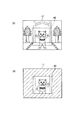
このデジタルカメラ1は、略矩形の薄板状ボディの前面に、撮影レンズ2、セルフタイマランプ3、光学ファインダ窓4、マイクロホン部5、ストロボ発光部6、及びラバーグリップ7を配設し、上面の(ユーザにとって)右端側には電源キー8及びシャッタキー9を配する。
The
ラバーグリップ7は、ユーザが撮影時にデジタルカメラ1を右手で筐体右側面側から把持した場合に右手中指、薬指、及び小指が確実に該筐体を把持できるように配設されたゴム製の帯状突起である。
The
また、電源キー8は、電源のオン/オフ毎に操作するためのキーである。シャッタキー9は、撮影タイミングを指示するためのキーである。
The
また、デジタルカメラ1の背面には、モードスイッチ(SW)10、スピーカ部11、メニューキー12、十字キー13、セットキー14、光学ファインダ15、ストロボチャージランプ16、及び表示部17を配する。
On the back of the
モードスイッチ10は、例えばスライドキースイッチにより構成され、基本モードである記録モード「R」と再生モード「P」を切り換えるためのものである。前記記録モード「R」には、静止画モード「R1」、動画モード「R2」、部分動画モード「R3」が含まれる。静止画モード「R1」は静止画の撮影を行うためのモード、動画モード「R1」は動画の撮影を行うためのモードであり、通常の撮影用のものである。これに対し、部分動画モード「R3」は静止画の一部を動画撮影するためのモードであって、特殊撮影用として用いられる。以下の説明では、この部分動画モード「R3」により特殊撮影を行う場合が主となる。
The
前記シャッタキー9は、これらのモード「R1」、「R2」、「R3」に共通に使用される。すなわち、静止画モード「R1」では、シャッタキー9が押下されたときのタイミングで静止画の撮影が行われる。動画モード「R2」では、シャッタキー9が押下されたときのタイミングで動画の撮影が開始され、シャッタキー9が再度押下されたときにその動画の撮影が終了する。部分動画モード「R3」では、シャッタキー9が押下されたときのタイミングで、まず、静止画の撮影が行われた後、動画撮影が開始される。そして、シャッタキー9が再度押下されたときに、そのときの動画撮影が終了する。 The shutter key 9 is commonly used for these modes “R1”, “R2”, and “R3”. That is, in the still image mode “R1”, a still image is taken at the timing when the shutter key 9 is pressed. In the moving image mode “R2”, shooting of a moving image starts at the timing when the shutter key 9 is pressed, and shooting of the moving image ends when the shutter key 9 is pressed again. In the partial moving image mode “R3”, at the timing when the shutter key 9 is pressed, first, a still image is shot, and then moving image shooting is started. When the shutter key 9 is pressed again, the moving image shooting at that time ends.
メニューキー12は、各種メニュー項目等を選択させる際に操作する。十字キー13は、上下左右各方向へのカーソル移動用のキーが一体に形成されたものであり、表示されているメニュー項目等を移動させる際に操作する。セットキー14は、前記十字キー13の中心位置に配置され、その時点で選択されているメニュー項目内容等を設定するために操作する。
The
ストロボチャージランプ16は、光学ファインダ15に近接して配設されたLEDランプでなり、このデジタルカメラ1のユーザが光学ファインダ15を覗いている場合と表示部17を見ている場合のいずれであってもストロボのチャージ状態等をユーザに視認させる。
The
表示部17は、バックライト付きのカラー液晶パネルで構成されるもので、撮影時には電子ファインダとしてスルー画像のモニタ表示を行う一方で、再生時には再生対象として選択された画像等を表示する。
The
なお、図示はしないがデジタルカメラ1の底面には、記録媒体として用いられるメモリカードを着脱するためのメモリカードスロットや、外部のパーソナルコンピュータ等と接続するためのシリアルインタフェースコネクタとして、例えばUSB(Universal Serial Bus)コネクタ等が設けられる。
Although not shown, the
図2はデジタルカメラ1の電子回路構成を示すブロック図である。
FIG. 2 is a block diagram showing an electronic circuit configuration of the
このデジタルカメラ1には、前記撮影レンズ2を構成するレンズ光学系22がモータ21の駆動により光軸方向に所定の範囲内で移動可能に設けられており、その光軸後方に撮像素子であるCCD23が配設されている。このCCD23は、撮影レンズ2を通過する光を受光し、その受光量に応じた画像データを取得する。
In this
基本モードである記録モード時において、CCD23がタイミング発生器(TG)24、垂直ドライバ25によって走査駆動され、一定周期毎に結像した光像に対応する光電変換出力を1画面分出力する。
In the recording mode, which is the basic mode, the
このCCD23の光電変換出力は、アナログ値の信号の状態でRGBの各原色成分毎に適宜ゲイン調整された後に、サンプルホールド回路26でサンプルホールドされ、A/D変換器27でデジタルデータに変換される。そして、カラープロセス回路28において、画素補間処理及びγ補正処理を含むカラープロセス処理が行われて、デジタル値の輝度信号Y及び色差信号Cb,Crが生成され、DMA(Direct Memory Access)コントローラ29に出力される。
The photoelectric conversion output of the
DMAコントローラ29は、カラープロセス回路28の出力する輝度信号Y及び色差信号Cb,Crを、同じくカラープロセス回路28からの複合同期信号、メモリ書込みイネーブル信号、及びクロック信号を用いて一度DMAコントローラ29内部のバッファに書込み、DRAMインタフェース(I/F)30を介してバッファメモリとして使用されるDRAM31にDMA転送を行う。
The
制御部32は、CPUと、このCPUで実行される動作プログラムを記憶したROM、及びワークメモリとして使用されるRAMなどを含むマイクロコンピュータにより構成される。この制御部32は、デジタルカメラ1全体の制御動作を司り、前記輝度及び色差信号のDRAM31へのDMA転送終了後に、この輝度及び色差信号をDRAMインタフェース30を介してDRAM31より読出し、VRAMコントローラ33を介してVRAM34に書込む。
The
デジタルビデオエンコーダ35は、前記輝度及び色差信号をVRAMコントローラ33を介してVRAM34より定期的に読出し、これらのデータを元にビデオ信号を発生して表示部17に出力する。
The
この表示部17は、上述した如く撮影時にはモニタ表示部(電子ファインダ)として機能するもので、デジタルビデオエンコーダ35からのビデオ信号に基づいた表示を行うことで、その時点でVRAMコントローラ33から取込んでいる画像情報に基づく画像をリアルタイムに表示することとなる。
The
このように、表示部17にその時点での画像がモニタ画像としてリアルタイムに表示されている状態で、例えば静止画撮影を行いたいタイミングでシャッタキー9を押下操作すると、トリガ信号が発生する。
As described above, when the shutter key 9 is pressed at a timing when it is desired to take a still image while the image at that time is displayed in real time on the
制御部32は、このトリガ信号に応じて、その時点でCCD23から取込んでいる1画面分の輝度及び色差信号のDRAM31へのDMA転送の終了後、直ちにCCD23からのDRAM31への経路を停止し、記録保存の状態に遷移する。
In response to the trigger signal, the
この記録保存の状態では、制御部32がDRAM31に書込まれている1フレーム分の輝度及び色差信号をDRAMインタフェース30を介してY,Cb,Crの各コンポーネント毎に縦8画素×横8画素の基本ブロックと呼称される単位で読み出して、画像処理部37の内部に存在するJPEG(Joint Photograph coding Experts Group)処理ブロックに書込み、この画像処理部37でADCT(Adaptive Discrete Cosine Transform:適応離散コサイン変換)、エントロピ符号化方式であるハフマン符号化等の処理によりデータ圧縮する。
In this record storage state, the
そして、得た符号データを1画像のデータファイルとして該画像処理部37から読出して記録用のメモリ38に書き込む。このメモリ38としては、予め本体に内蔵されたメモリの他に、記録媒体として着脱自在に装着されるメモリカードなどを含む。1フレーム分の輝度及び色差信号の圧縮処理及びメモリ38への全圧縮データの書込み終了に伴なって、制御部32はCCD23からDRAM31への経路を再び起動する。
The obtained code data is read out from the
また、制御部32には、さらにUSBインタフェース(I/F)39、ストロボ駆動部40が接続される。
Further, a USB interface (I / F) 39 and a
USBインタフェース39は、USBコネクタを介して有線接続されるパーソナルコンピュータ等の他の情報端末装置との間で画像データその他の送受を行う場合の通信制御を行う。ストロボ駆動部40は、撮影時時図示せぬストロボ用の大容量コンデンサを充電した上で、制御部32からの制御に基づいて前記ストロボ発光部6を閃光駆動する。
The
なお、前記キー入力部36は、上述したシャッタキー9の他に、前記電源キー8、モードスイッチ10、メニューキー12、十字キー13及びセットキー14等から構成され、それらのキー操作に伴なう信号は直接制御部32へ送出される。
The key input unit 36 includes the
また、静止画像ではなく動画像の撮影時においては、シャッタキー9が押下操作されたときに、上述した画像処理部37の内部に存在する動画処理ブロックで、MPEG(Moving Picture Expert Group)やmotion−JPEGなどの手法により撮影動画をデータ圧縮し、この撮影動画データをメモリ38へ記録する。そして、再度シャッタキー9が操作されると、動画データの記録を終了する。
In addition, when shooting a moving image instead of a still image, a moving picture processing group (MPEG) or motion is a moving image processing block existing inside the
一方、基本モードである再生モード時には、制御部32がメモリ38に記録されている画像データを選択的に読出し、画像処理部37で記録モード時にデータ圧縮した手順と全く逆の手順で圧縮されている画像データを伸長する。そして、この伸長した画像データをDRAMインタフェース30を介してDRAM31に保持させた上で、このDRAM31の保持内容をVRAMコントローラ33を介してVRAM34に記憶させ、このVRAM34より定期的に画像データを読出してビデオ信号を発生し、表示部17で再生出力させる。
On the other hand, in the playback mode which is the basic mode, the
選択した画像データが静止画像ではなく動画像であった場合には、その選択した動画像ファイルを構成するMPEG動画データの再生を実行し、すべての動画像データの再生を終了した時点で、例えば、次に再生の指示がなされるまで先頭に位置する静止画像データを表示するなどを行う。 When the selected image data is not a still image but a moving image, reproduction of MPEG moving image data constituting the selected moving image file is executed, and when reproduction of all moving image data is completed, for example, Then, the still image data positioned at the head is displayed until the next reproduction instruction is given.
この他に、特に図示しないが、例えば携帯時の電源として用いられるバッテリとそのバッテリの電圧供給制御部や、マイク5およびスピーカ11に対する音声データの処理を行うための音声処理部などが備えられている。
In addition to this, although not particularly shown, for example, a battery used as a power source for carrying, a voltage supply control unit for the battery, a voice processing unit for processing voice data for the
次に、前記構成のデジタルカメラ1を用いて、上述した部分動画撮影を行う場合の動作についてフローチャートを参照しながら説明する。なお、以下の各フローチャートで示される処理は、マイクロプロセッサである制御部32がROMなどに記憶されたプログラムを読み込むことにより実行される。
Next, the operation when performing the above-described partial moving image shooting using the
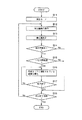
図3は第1の実施形態におけるデジタルカメラ1の撮影時の処理動作を示すフローチャートである。
FIG. 3 is a flowchart showing a processing operation at the time of photographing by the
まず、ユーザは図1に示すモードスイッチ10を操作してモード選択を行う(ステップA11)。このモードスイッチ10によって選択可能なモードとして、記録モード「R」と再生モード「P」があり、さらに、前記記録モード「R」には静止画モード「R1」、動画モード「R2」、部分動画モード「R3」がある。
First, the user operates the
ここで、特殊撮影用の部分動画モード「R3」が選択されると(ステップA12のYes)、図4に示すように、撮影時に電子ファインダとして機能する表示部17の画面(モニタ画面)上に動画エリア設定用のカーソル41が表示される(ステップA13)。ユーザは、このカーソル41を例えば十字キー13の操作により移動させて、同モニタ画面上に動画エリア42を任意に設定する(ステップA14)。
Here, when the partial moving image mode “R3” for special shooting is selected (Yes in Step A12), as shown in FIG. 4, on the screen (monitor screen) of the
この動画エリア42は、動画を撮影する範囲を示している。すなわち、表示部17の画面全体を静止画エリアとし、その静止画エリアの中の一部を動画エリア42としている。なお、この動画エリア42の設定方法としては、カーソル操作による方法の他に、例えば表示部17をタッチパネルで構成することで、画面に直接触れて設定するような方法であっても良い。
The moving
また、この動画エリア42の形状についても特に限定されるものではなく、ユーザが任意の形を指定できるものとする。以下では、説明を簡単にするため、図4に示すような矩形状の動画エリア42を想定する。
Further, the shape of the moving
前記モニタ画面上に動画エリア42が設定された状態で、シャッタキー9の押下操作により撮影指示がなれると(ステップA15のYes)、まず、CCD23の全撮影エリアを通じて静止画の撮影が行われ、そのときに得られた静止画の画像データが所定の圧縮方式により圧縮されてメモリ38に記録される(ステップA16)。
When a shooting instruction is issued by pressing the shutter key 9 while the moving
この静止画の記録は1枚分だけである。続いて、CCD23の当該静止画の中の前記設定された動画エリア42に対応した部分を通じて部分動画の撮影が開始される。このときに得られた動画の画像データは所定の圧縮方式により圧縮された後、前記静止画の画像データと関連付けられて記録される(ステップA17)。この動画撮影は、シャッタキー9が再度押下されるまでの間、継続的に行われ、その間に得られた画像データがメモリ38に記録される。
This still image is recorded only for one sheet. Subsequently, shooting of a partial moving image is started through a portion corresponding to the set moving
そして、シャッタキー9が押下されて撮影の終了指示がなされると(ステップA18のYes)、ここでの撮影動作が終了する。 When the shutter key 9 is pressed and an instruction to end shooting is given (Yes in step A18), the shooting operation here ends.
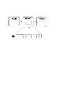
図5に上述した撮影処理によって得られる静止画の画像データと動画の画像データの構成を示す。 FIG. 5 shows a configuration of still image data and moving image data obtained by the above-described photographing process.
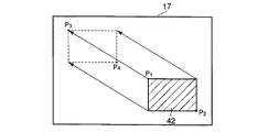
上述したように、部分動画モード「R3」が設定された状態では、1回の撮影操作により全画面の静止画データとその静止画の一部を動画撮影した動画データが同時に得られる。その際、全画面の静止画データには、部分動画付きであることを示すフラグ情報「F」が付加される。一方、動画データには、動画エリア42の位置データが付加される。図4の例では、動画エリア42の点P1、P2のXY座標値が位置データとして付加されることになる。
As described above, in the state in which the partial moving image mode “R3” is set, the still image data of the entire screen and the moving image data obtained by capturing a moving image of a part of the still image are obtained at the same time by one shooting operation. At that time, flag information “F” indicating that a partial moving image is attached is added to still image data of the entire screen. On the other hand, the position data of the moving
また、これらの静止画データと動画データには、それぞれに共通のID(識別情報)が付加されて互いに関連付けられてメモリ38に記録される。
Further, a common ID (identification information) is added to each of the still image data and the moving image data, and is associated with each other and recorded in the
ここで、撮影時の様子を具体例を挙げて説明する。 Here, a state at the time of photographing will be described with a specific example.
図6はデジタルカメラ1の撮影時のモニタ画面の状態を示す図であり、図6(a)は静止画撮影時の表示状態、同図(b)は動画撮影時の表示状態を示している。
6A and 6B are diagrams showing the state of the monitor screen when the
静止画の撮影時には、図6(a)に示すように、表示部17の画面全体が撮影対象となる。その際、現在設定されている動画エリア42を例えば点線枠などの特定の表示形態にて表示するようにしても良い。この状態で、シャッタキー9を押下操作すると、その時点で表示されている画像が静止画の画像データとして取り込まれてメモリ38に記録される。
When a still image is shot, the entire screen of the
静止画の撮影後、直ちに動画撮影に自動的に切り替わる。動画の撮影時には、図6(b)に示すように、動画エリア42内の表示部分だけが撮影対象となり、その部分の画像が動画の画像データとして順次取り込まれてメモリ38に記録される。この場合、上述したように静止画データと同じIDが付加されてメモリ38に記録されることで、両者のデータが関連付けられる。
Immediately after shooting a still image, it automatically switches to movie shooting. At the time of shooting a moving image, as shown in FIG. 6B, only the display portion in the moving
なお、図6(b)において、部分動画を撮影する際に、その撮影対象となる動画エリア42以外の部分(斜線で示した部分)の表示に関して特に限定されるものではないが、例えばブルーバックのような特定の背景パターンを表示したり、直前に撮影した静止画像を表示したり、撮影中のスルー画像を半透明で表示するなどしても良い。
In FIG. 6B, when a partial moving image is shot, there is no particular limitation regarding the display of a portion other than the moving
次に、再生時の処理動作について説明する。 Next, the processing operation during reproduction will be described.
図7は第1の実施形態におけるデジタルカメラ1の再生時の処理動作を示すフローチャートである。
FIG. 7 is a flowchart showing the processing operation during playback of the
ユーザが図1に示すモードスイッチ10の操作により再生モード「P」を選択した後(ステップB11)、十字キー13の操作により静止画の表示を指示すると(ステップB12)、メモリ38に現在記録されている静止画の画像データが読み出されて、その静止画データが表示部17に再生表示される(ステップB13)。その際、複数枚の静止画がメモリ38に記録されていれば、十字キー13の操作に伴い、これらが順に読み出されて表示部17に表示されることになる。
After the user selects the playback mode “P” by operating the
ここで、表示部17に静止画データが表示される毎に、当該静止画に部分動画が付加されているか否かが判断される(ステップB14)。この判断は、図5に示すように、静止画データにフラグ情報が付加されているか否かによって行う。フラグ情報が付加されていれば、部分動画ありと判断される(ステップB14のYes)。
Here, each time still image data is displayed on the
そして、当該静止画が一定時間T(例えば0.1秒)以上連続して表示されたときに(ステップB15のYes)、部分動画の再生が選択されたものと判断されて、当該静止画に関連した動画の画像データがメモリ38から読み出されて再生表示される(ステップB16)。
Then, when the still image is continuously displayed for a certain time T (for example, 0.1 second) or more (Yes in Step B15), it is determined that the reproduction of the partial moving image is selected, and the still image is displayed. The image data of the related moving image is read from the
詳しく説明すると、まず、図5に示すように、静止画データのIDに基づいてメモリ38から同じIDを有する動画データが関連画像として読み出される。そして、その動画データに付加された位置データに基づいて表示位置が判断され、そこに動画データの再生表示が行われる。図5の例では、前記位置データとしてP1とP2の2点の座標データが付加されている。したがって、静止画の表示後、その中でP1とP2で定められる動画エリア42の位置に動画データが再生表示されることになる。
More specifically, first, as shown in FIG. 5, moving image data having the same ID is read out as a related image from the
なお、動画エリア42以外の静止画部分については、そのまま表示した状態にしても良いし、非表示とすることでも良い。このときの静止画部分を表示状態とするか非表示状態とするのかは、例えばメニューキー12の操作により表示される各種設定画面を用いて任意に設定可能である。
Note that the still image portion other than the moving
動画データの表示が終了すると(ステップB17のYes)、次の静止画データが表示される(ステップB13)。そして、前記同様にして動画データが付加されていれば、一定時間Tの経過後に動画データの表示が行われる(ステップB14〜B17)。この場合、前記一定時間Tが経過する前にユーザが次の表示指示を行えば、動画データの表示は行われず、次の静止画データが表示されることになる。このTの値は、固定値であっても良いし、前記各種設定画面を用いて任意に設定できるようにしても良い。 When the display of the moving image data is completed (Yes in step B17), the next still image data is displayed (step B13). If the moving image data is added in the same manner as described above, the moving image data is displayed after a predetermined time T has elapsed (steps B14 to B17). In this case, if the user gives the next display instruction before the predetermined time T has elapsed, the moving image data is not displayed and the next still image data is displayed. The value of T may be a fixed value or may be arbitrarily set using the various setting screens.
図示せぬ再生終了ボタン等の押下により再生終了の指示があると(ステップB18のYes)、ここでの一連の再生処理が終了する。 When a playback end instruction is issued by pressing a playback end button (not shown) or the like (Yes in step B18), a series of playback processing ends here.
図8に上述した再生処理によって表示される静止画と動画との関係を示す。 FIG. 8 shows the relationship between a still image and a moving image displayed by the reproduction process described above.
今、3枚の静止画a,b,cがメモリ38に記録されているものとする。所定の操作により、これらの静止画a,b,cが表示部17に順に再生表示される。ここで、静止画bが表示された際に、前記一定時間Tの経過後に、この静止画bに設定された動画エリア42に部分動画が再生表示される。
Assume that three still images a, b, and c are recorded in the
この部分動画の再生後、次の静止画cの表示に移る。この場合、ユーザが静止画bの表示時に前記一定時間Tの経過前に次の表示を指示すれば、前記部分動画は表示されずに、次の静止画cが表示されることになる。 After the reproduction of the partial moving image, the next still image c is displayed. In this case, if the user indicates the next display before the fixed time T when the still image b is displayed, the next still image c is displayed without displaying the partial moving image.
以上のように本発明の第1の実施形態によれば、撮影時のモニタ画面上で動画撮影したい部分に動画エリア42を任意に設定しておくことにより、全画面の静止画の撮影後、前記設定された動画エリアに対応した部分の動画撮影を行うことができる。
As described above, according to the first embodiment of the present invention, the moving
これにより、例えば図6に示すように、部分的に動きのある被写体を撮影するような場合に、静止画を背景とし、その中に前記動き部分を動画撮影した画像を嵌め込んだユニークな画像データを簡単に得ることができる。また、このような部分的な動画撮影により、画面全体を常に動画撮影する場合に比べてメモリ容量を大場に削減でき、その結果、動画の撮影時間を延ばすことができる。 Thus, for example, as shown in FIG. 6, when shooting a subject that is partially moving, a unique image in which a still image is used as a background and an image obtained by shooting the moving portion in the moving image is inserted therein. Data can be easily obtained. In addition, such partial moving image shooting can reduce the memory capacity to a large area as compared to the case where the entire screen is always shot, and as a result, the moving image shooting time can be extended.
さらに、動画エリア42は固定ではなく、その位置やサイズなどを含めて任意に設定することができるので、撮影対象となる被写体の制約を受けることなく、その都度、動画撮影を必要とする部分だけを任意に指定して、動画撮影することが可能である。
Furthermore, since the moving
なお、前記実施形態では、動画エリア42を1つとしたが、複数の動画エリア42を設定するようにしも良い。この場合、各エリア毎に得られた動画データにそれぞれのエリアの位置データが付加され、共通のIDにて静止画データと関連付けてメモリ38に記録されることになる。再生時には、静止画データの表示後、その静止画データに関連した各動画データが前記IDに従ってメモリ38から読み出され、これらに付加された位置データに基づいて当該静止画中の所定の位置に再生表示されることになる。
In the above embodiment, the number of moving
(第2の実施形態)
次に、本発明の第2の実施形態について説明する。
(Second Embodiment)
Next, a second embodiment of the present invention will be described.
第2の実施形態は、全画面の静止画の撮影後、動画エリアの動画撮影を行い、その動画撮影終了後に再び静止画の撮影を行うようにしたことを特徴としている。 The second embodiment is characterized in that after a still image of a full screen is shot, a moving image is shot in the moving image area, and a still image is shot again after the moving image is shot.
図9は本発明の第2の実施形態におけるデジタルカメラ1の撮影時の処理動作を示すフローチャートである。
FIG. 9 is a flowchart showing a processing operation at the time of photographing by the
前記第1の実施形態(図3)と同様に、まず、図1に示すモードスイッチ10の操作によりモード選択が行われる(ステップC11)。そして、特殊撮影用の部分動画モード「R3」が選択されると(ステップC12のYes)、図4に示すように、撮影時に電子ファインダとして機能する表示部17の画面(モニタ画面)上に動画エリア設定用のカーソル41が表示される(ステップC13)。ユーザは、このカーソル41を例えば十字キー13の操作により移動させて、同モニタ画面上に動画エリア42を任意に設定する(ステップC14)。
As in the first embodiment (FIG. 3), first, mode selection is performed by operating the
ここで、モニタ画面上に動画エリア42が設定された状態で、シャッタキー9の押下操作により撮影指示がなれると(ステップC15のYes)、まず、CCD23の全撮影エリアを通じて静止画の撮影が行われ、そのときに得られた静止画の画像データが所定の圧縮方式により圧縮されてメモリ38に記録される(ステップC16)。
Here, in a state where the moving
この静止画の記録は1枚分だけである。続いて、CCD23の当該静止画の中の前記設定された動画エリア42に対応した部分を通じて部分動画の撮影が開始される。このときに得られた動画の画像データは所定の圧縮方式により圧縮された後、前記静止画の画像データと関連付けられて記録される(ステップC17)。この動画撮影は、再度シャッタキー9が押下されるまでの間、継続的に行われる。
This still image is recorded only for one sheet. Subsequently, shooting of a partial moving image is started through a portion corresponding to the set moving
また、シャッタキー9が再度押下操作されて撮影の終了指示がなされると(ステップC18のYes)、前記動画エリア42内の動画撮影が終了する。その際、全画面の静止画撮影が行われ、そのときに得られた静止画の画像データが所定の圧縮方式により圧縮されてメモリ38に記録された後に、ここでの全ての撮影動作が終了する(ステップC19)。
When the shutter key 9 is pressed again and an instruction to end shooting is given (Yes in step C18), the moving image shooting in the moving
ここで、撮影時の様子を具体例を挙げて説明する。 Here, a state at the time of photographing will be described with a specific example.
図10はデジタルカメラ1の再生時のモニタ画面の状態を示す図であり、図10(a)は1枚目の静止画撮影時の表示状態、同図(b)は動画撮影時の表示状態、同図(c)は2枚目の静止画撮影時の表示状態を示している。
10A and 10B are diagrams showing the state of the monitor screen during playback of the
静止画の撮影時には、図10(a)に示すように、表示部17の画面全体が撮影対象となり、シャッタキー9の押下操作に伴い、その時点で表示されている画像が1枚目の静止画の画像データとして取り込まれてメモリ38に記録される。
At the time of shooting a still image, as shown in FIG. 10A, the entire screen of the
静止画の撮影後、直ちに動画撮影に自動的に切り替わる。動画の撮影時には、図10(b)に示すように、動画エリア42内の表示部分だけが撮影対象となり、その部分の画像が動画の画像データとして順次取り込まれてメモリ38に記録される。
Immediately after shooting a still image, it automatically switches to movie shooting. At the time of shooting a moving image, as shown in FIG. 10B, only the display portion in the moving
さらに、動画撮影の終了後、図10(c)に示すように、その動画撮影後の状態が静止画で撮影され、そのときに得られた画像データが2枚目の静止画の画像データとして取り込まれる。これらの画像データは、図5で説明したように、共通のIDによって互いに関連付けられてメモリ38に記録される。
Further, after the end of the moving image shooting, as shown in FIG. 10C, the state after the moving image shooting is shot as a still image, and the image data obtained at that time is used as the image data of the second still image. It is captured. As described with reference to FIG. 5, these image data are associated with each other by a common ID and recorded in the
なお、図10(b)において、部分動画を撮影する際に、前記図6(b)の場合と同様に、撮影対象となる動画エリア42以外の部分(斜線で示した部分)の表示に関して、例えばブルーバックのような特定の背景パターンや直前に撮影した静止画像を表示したり、撮影中のスルー画像を半透明で表示するなどしても良い。
In FIG. 10B, when shooting a partial moving image, as in the case of FIG. 6B, regarding the display of a portion other than the moving
次に、再生時の処理動作について説明する。 Next, the processing operation during reproduction will be described.
図11は第2の実施形態におけるデジタルカメラ1の再生時の処理動作を示すフローチャートである。
FIG. 11 is a flowchart showing the processing operation during playback of the
前記第1の実施形態(図9)と同様に、ユーザが図1に示すモードスイッチ10の操作により再生モード「P」を選択した後(ステップD11)、十字キー13の操作により静止画の表示を指示すると(ステップD12)、メモリ38に現在記録されている静止画の画像データが読み出されて、その静止画データが表示部17に再生表示される(ステップD13)。その際、複数枚の静止画がメモリ38に記録されていれば、十字キー13の操作に伴い、これらが順に読み出されて表示部17に表示されることになる。
As in the first embodiment (FIG. 9), after the user selects the playback mode “P” by operating the
ここで、表示部17に静止画データが表示される毎に、当該静止画に部分動画が付加されているか否かが判断される(ステップD14)。この判断は、図5に示すように、静止画データにフラグ情報が付加されているか否かによって行う。フラグ情報が付加されていれば、部分動画ありと判断される(ステップD14のYes)。そして、一定時間Tが経過したときに(ステップD15のYes)、当該静止画に関連した動画の画像データがメモリ38から読み出されて再生表示される(ステップD16)。
Here, every time still image data is displayed on the
詳しくは、静止画データのIDに基づいてメモリ38から同じIDを有する動画データが読み出される。そして、その動画データに付加された位置データに基づいて表示位置が判断され、そこに動画データが再生表示される。
Specifically, moving image data having the same ID is read from the
ここで、動画データの再生終了後に、この動画データに関連した2枚目の静止画データが前記IDに基づいてメモリ38から検索され、その静止画データが再生表示される(ステップD18)。前記2枚目の静止画データとは、部分動画の撮影後に撮影された画面全体の静止画データである。
Here, after the reproduction of the moving image data is completed, the second still image data related to the moving image data is retrieved from the
以下同様にして、再生終了の指示があるまで(ステップD19のYes)、各静止画データが順次表示され(ステップD13)、動画データが付加されていれば、一定時間Tの経過後に動画データの表示と2枚目の静止画データの表示が行われる(ステップD14〜D18)。この場合、前記一定時間Tが経過する前にユーザが次の表示指示を行えば、動画データの表示は行われず、次の静止画データが表示されることになる。 In the same manner, until an instruction to end playback (Yes in step D19), each still image data is sequentially displayed (step D13). If movie data is added, the movie data The display and the second still image data are displayed (steps D14 to D18). In this case, if the user gives the next display instruction before the predetermined time T has elapsed, the moving image data is not displayed and the next still image data is displayed.
図12に上述した再生処理によって表示される静止画と動画との関係を示す。 FIG. 12 shows the relationship between a still image and a moving image displayed by the reproduction process described above.
今、4枚の静止画a,b1,b2,cがメモリ38に記録されているものとする。このうち、静止画b1とb2は部分動画の1枚目と2枚目として関連付けられているものとすると、所定の操作により1枚目の静止画b1が表示された際に、前記一定時間Tの経過後に、この静止画b1の動画エリア42に部分動画が再生表示される。そして、この部分動画の再生後、2枚目の静止画b2が表示される。
Assume that four still images a, b1, b2, and c are recorded in the
この場合、ユーザが静止画b1の表示時に前記一定時間Tの経過前に次の表示を指示すれば、前記部分動画は表示されずに、次の静止画cが表示されることになる。 In this case, if the user indicates the next display before the fixed time T when the still image b1 is displayed, the next still image c is displayed without displaying the partial moving image.
以上のように本発明の第2の実施形態によれば、静止画の一部を動画撮影すると共に、最後に全体の静止画を撮影するようにしたことで、動画撮影中にその撮影対象外の部分(動画エリア42以外の部分)で変化があった場合に、その変化状況を2枚目の静止画で確認することができる。 As described above, according to the second embodiment of the present invention, a part of a still image is captured as a moving image, and finally the entire still image is captured. When there is a change in the portion (portion other than the moving image area 42), the change state can be confirmed on the second still image.
なお、前記第1の実施形態と同様に、動画エリア42は1つに限らず、複数設定可能であり、各エリアに対応した動画撮影を行った後、全体の静止画を撮影するようにしても良い。
As in the first embodiment, the number of moving
(第3の実施形態)
次に、本発明の第3の実施形態について説明する。
(Third embodiment)
Next, a third embodiment of the present invention will be described.
第3の実施形態では、静止画の撮影後にその静止画の一部を動画撮影する場合において、この動画撮影のタイミングを任意に設定可能とするものである。 In the third embodiment, when a part of the still image is captured after the still image is captured, the timing for capturing the movie can be arbitrarily set.
具体的には、動画エリア42を設定した際に、その動画エリア42に対する撮影タイミング(撮影開始時間と撮影時間)を任意にスケジュール設定する。この場合、動画エリア42が複数設定されていれば、これらのエリエ毎にそれぞれの撮影タイミングを任意に設定可能とする。
Specifically, when the moving
各エリアの撮影タイミングを示すスケジュールデータは、例えば制御部32内に設けられたスケジュール記憶部32aに記憶される。そして、このスケジュール記憶部32aに記憶されたスケジュールデータに基づいて各エリアに対する動画の撮影動作が制御される。
Schedule data indicating the shooting timing of each area is stored in, for example, a
以下に、その処理動作について説明する。 The processing operation will be described below.
図13は本発明の第3の実施形態におけるデジタルカメラ1の撮影時の処理動作を示すフローチャートである。
FIG. 13 is a flowchart showing a processing operation at the time of photographing by the
前記第1の実施形態(図3)と同様に、まず、図1に示すモードスイッチ10の操作によりモード選択が行われる(ステップE11)。そして、特殊撮影用の部分動画モード「R3」が選択されると(ステップE12のYes)、図4に示すように、撮影時に電子ファインダとして機能する表示部17の画面(モニタ画面)上に動画エリア設定用のカーソル41が表示される(ステップE13)。ユーザは、このカーソル41を例えば十字キー13の操作により移動させて、同モニタ画面上に動画エリア42を任意に設定する(ステップE14)。
As in the first embodiment (FIG. 3), first, mode selection is performed by operating the
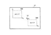
今、図14に示すように、モニタ画面上で2つの動画エリア42a(Aエリア)、動画エリア42b(Bエリア)が設定されたものとして説明する。
Now, as shown in FIG. 14, it is assumed that two moving
第3の実施形態では、動画エリア設定後、例えば図15に示すようなスケジュール設定画面51が自動的あるいはメニューキー12の操作に伴って表示部17に表示される。このスケジュール設定画面51には、前記設定された動画エリア42a、42bに対応したスケジュールバー52a、52bが設けられており、このスケジュールバー52a、52b上で時間軸53a、53bを移動させるなどして、それぞれの撮影タイミング(撮影開始時間と撮影時間)を設定するように構成されている。
In the third embodiment, after the moving image area is set, for example, a
このスケジュール設定画面51で設定された動画エリア42a、42bに対する撮影タイミングを示すスケジュールデータは、制御部32内のスケジュール記憶部32aに記憶される(ステップE15)。
The schedule data indicating the shooting timing for the moving
このようにして、モニタ画面上に動画エリア42a、42bが設定されると共に、これらの動画エリア42a、42bに対する撮影タイミングのスケジュール設定がなされた状態で、シャッタキー9の押下操作により撮影指示がなれると(ステップE16のYes)、まず、CCD23の全撮影エリアを通じて静止画の撮影が行われ、そのときに得られた静止画の画像データが所定の圧縮方式により圧縮されてメモリ38に記録される(ステップE17)。
In this manner, the moving
この静止画の記録は1枚分だけである。続いて、CCD23の当該静止画の中の前記設定された動画エリア42a、42bに対応した部分を通じて部分動画の撮影が開始される。その際、制御部32のスケジュール記憶部32aに記憶されたスケジュールデータに従って前記動画エリア42a、42bに対する動画撮影が指定の順で行われる(ステップE18)。前記動画エリア42a、42b毎に得られた動画の画像データは所定の圧縮方式により圧縮された後、前記静止画の画像データと関連付けられてメモリ38に記録される。
This still image is recorded only for one sheet. Subsequently, shooting of a partial moving image is started through a portion corresponding to the set moving
そして、所定時間分の動画撮影が終了するか、あるいは、シャッタキー9が再度押下操作されて撮影の終了指示がなされると(ステップE19のYes)、ここでの撮影動作が終了する。 Then, when the moving image shooting for a predetermined time is completed, or when the shutter key 9 is pressed again to give an instruction to end the shooting (Yes in step E19), the shooting operation ends here.
上述した撮影処理について具体例を挙げて説明する。 The shooting process described above will be described with a specific example.
図16は動画エリア42a、42bに対する撮影タイミングのスケジュール設定例を示す図である。上述したように、動画エリア42a、42bを設定した後に、これらに対する撮影タイミングを個々に設定することができる。図16の例では、シャッタキー9の押下により全画面の静止画の撮影後、t1(A)時間経過したら動画エリア42a(Aエリア)の部分動画をt2(A)時間だけ撮影し、動画エリア42b(Bエリア)についても、静止画の撮影後にt1(B)時間経過したらt2(B)時間だけ撮影することが設定されている。
FIG. 16 is a diagram showing a schedule setting example of shooting timing for the moving
ここで、t1(A)よりもt1(B)の方が時間的に早ければ、静止画の撮影後に、まず、動画エリア42a(Aエリア)の部分動画が撮影され、続いて、動画エリア42b(Bエリア)の部分動画が撮影されることになる。また、t2(A)よりもt2(B)の方が時間的に早ければ、動画エリア42a(Aエリア)の撮影後、t2(B)時間が経過するまでの間、動画エリア42b(Bエリア)だけの撮影が続く。
Here, if t1 (B) is earlier in time than t1 (A), after shooting a still image, first, a partial moving image in moving
なお、図16の例では、動画エリア42b(Bエリア)の撮影がt2(B)時間行われた後、ここでの部分画像の撮影が自動的に終了することになるが、最終的な撮影終了の指示をシャッタキー9の押下によって明示的に行うことでも良い(図13のステップE19参照)。
In the example of FIG. 16, after the moving
図17に上述したデジタルカメラ1の撮影処理によって得られる静止画の画像データと動画の画像データの構成を示す。
FIG. 17 shows a configuration of still image data and moving image data obtained by the above-described photographing process of the
動画エリア42a、42bの撮影タイミングがスケジュール設定されている場合には、全画面の静止撮影後、動画エリア42a、42bに対する動画撮影がスケジュールデータに従って行われる。その際、全画面の静止画データには、部分動画付きであることを示すフラグ情報「F」が付加される。
When the shooting timing of the moving
一方、動画エリア42a、42bに対応した各動画データには、それぞれのエリアの位置データが付加される。図14の例では、動画エリア42a(Aエリア)に対応した動画データには点P1、P2のXY座標値が位置データとして付加され、動画エリア42b(Bエリア)に対応した動画データには点P3、P4のXY座標値が位置データとして付加されることになる。
On the other hand, position data of each area is added to each moving image data corresponding to the moving
また、これらの動画データには、スケジュールデータに含まれている撮影開始時間「t1(A)」、「t1(B)」がそれぞれ付加される。動画エリア42a(Aエリア)に対応した動画データは、撮影時間t2(A)分の連続したフレーム画像からなる。動画エリア42b(Bエリア)に対応した動画データは、撮影時間t2(B)分の連続したフレーム画像からなる。
In addition, shooting start times “t1 (A)” and “t1 (B)” included in the schedule data are added to these moving image data, respectively. The moving image data corresponding to the moving
また、これらの静止画データと各エリア毎の動画像データには、それぞれに共通のID(識別情報)が付加されて互いに関連付けられてメモリ38に記録される。
Further, a common ID (identification information) is added to each of the still image data and the moving image data for each area, and is associated with each other and recorded in the
ここで、撮影時の様子を具体例を挙げて説明する。 Here, a state at the time of photographing will be described with a specific example.
図18は撮影時におけるデジタルカメラ1のモニタ画面の状態を示す図であり、図18(a)は静止画撮影時の表示状態、同図(b)乃至(d)はスケジュールデータに従って切り替わる動画撮影時の表示状態を示している。
FIG. 18 is a diagram showing the state of the monitor screen of the
静止画の撮影時には、図18(a)に示すように、表示部17の画面全体が撮影対象となる。その際、現在設定されている動画エリア42a、42bを例えば点線枠などの特定の表示形態にて表示するようにしても良い。この状態で、シャッタキー9を押下操作すると、その時点で表示されている画像が静止画の画像データとして取り込まれてメモリ38に記録される。
When shooting a still image, as shown in FIG. 18A, the entire screen of the
静止画の撮影後、スケジュールデータに従って動画撮影が行われる。ここでは、まず、t1(A)時間後に、図18(b)に示すように、動画エリア42a(Aエリア)に対する動画撮影がt2(A)時間行われ、その間の動画の画像データが順次取り込まれてメモリ38に記録される。
After the still image is shot, moving image shooting is performed according to the schedule data. Here, first, after time t1 (A), as shown in FIG. 18B, moving image shooting is performed for the moving
また、動画エリア42a(Aエリア)と別に、静止画の撮影後からt1(B)時間経過すると、図18(c)に示すように、動画エリア42b(Bエリア)に対する動画撮影がt2(B)時間行われ、その間の動画の画像データが順次取り込まれてメモリ38に記録される。これらの動画データには、それぞれ静止画データと同じIDが付加されてメモリ38に記録される。
In addition to the moving
また、前記t2(A)時間結果すると、動画エリア42a(Aエリア)の動画撮影が終了し、図18(d)に示すように、動画エリア42b(Bエリア)だけの動画撮影が行われる。そして、t2(B)時間経過すると、この動画エリア42b(Bエリア)の動画撮影も終了する。
When the time t2 (A) results, the moving image shooting of the moving
なお、図18(b)〜(d)において、部分動画を撮影する際に、前記図6(b)の場合と同様に、撮影対象となる動画エリア42a、42b以外の部分(斜線で示した部分)の表示に関して、例えばブルーバックのような特定の背景パターンや直前に撮影した静止画像を表示したり、撮影中のスルー画像を半透明で表示するなどしても良い。
In FIGS. 18B to 18D, when shooting a partial moving image, as in the case of FIG. 6B, portions other than the moving
次に、再生時の処理動作について説明する。 Next, the processing operation during reproduction will be described.
図19は第3の実施形態におけるデジタルカメラ1の再生時の処理動作を示すフローチャートである。
FIG. 19 is a flowchart showing the processing operation during playback of the
ユーザが図1に示すモードスイッチ10の操作により再生モード「P」を選択した後(ステップF11)、十字キー13の操作により静止画の表示を指示すると(ステップF12)、メモリ38に現在記録されている静止画の画像データが読み出されて、その静止画データが表示部17に再生表示される(ステップF13)。その際、複数枚の静止画がメモリ38に記録されていれば、十字キー13の操作に伴い、これらが順に読み出されて表示部17に表示されることになる。
After the user selects the playback mode “P” by operating the
ここで、表示部17に静止画データが表示される毎に、当該静止画に部分動画が付加されているか否かが判断される(ステップF14)。この判断は、図17に示すように、静止画データにフラグ情報が付加されているか否かによって行う。フラグ情報が付加されていれば、部分動画ありと判断される(ステップF14のYes)。
Here, every time still image data is displayed on the
そして、当該静止画が一定時間T(例えば0.1秒)以上連続して表示されたときに(ステップF15のYes)、部分動画の再生が選択されたものと判断されて、該静止画に関連した動画データがメモリ38から読み出され、スケジュール設定された時間に従って再生表示される(ステップF16)。
Then, when the still image is continuously displayed for a certain time T (for example, 0.1 second) or more (Yes in Step F15), it is determined that the reproduction of the partial moving image is selected, and the still image is displayed. The related moving image data is read from the
詳しくは、静止画データのIDに基づいてメモリ38から同じIDを有する動画データが読み出される。そして、その動画データに付加された位置データに基づいて表示位置が判断され、そこに動画データが再生表示される。
Specifically, moving image data having the same ID is read from the
その際、再生表示のタイミングは、当該動画データに付加された撮影開始時間データに基づいて判断される。すなわち、図17の例で言えば、静止画の表示後、t1(A)時間経過したら動画エリア42a(Aエリア)の動画データがP1−P2で示される位置にその撮影時間t2(A)分表示されることになる。また、t1(B)時間経過したら動画エリア42b(Bエリア)の動画データがP3−P4で示される位置にその撮影時間t2(B)分表示されることになる。
At that time, the timing of reproduction display is determined based on the shooting start time data added to the moving image data. That is, in the example of FIG. 17, when t1 (A) time elapses after the still image is displayed, the moving image data in the moving
なお、前記第1の実施形態と同様に、動画エリア42a、42b以外の静止画部分については、そのまま表示した状態にしても良いし、非表示とすることでも良い。このときの静止画部分を表示状態とするか非表示状態とするのかは、例えばメニューキー12の操作により表示される各種設定画面を用いて任意に設定可能である。
As in the first embodiment, the still image portions other than the moving
動画データの表示が終了すると(ステップF17のYes)、次の静止画データが表示される(ステップF13)。そして、前記同様にして動画データが付加されていれば、一定時間Tの経過後に動画データの表示が行われる(ステップF14〜F17)。この場合、前記一定時間Tが経過する前にユーザが次の表示指示を行えば、動画データの表示は行われず、次の静止画データが表示されることになる。このTの値は、固定値であっても良いし、前記各種設定画面を用いて任意に設定できるようにしても良い。 When the display of the moving image data is completed (Yes in step F17), the next still image data is displayed (step F13). If moving image data is added in the same manner as described above, the moving image data is displayed after a predetermined time T has elapsed (steps F14 to F17). In this case, if the user gives the next display instruction before the predetermined time T has elapsed, the moving image data is not displayed and the next still image data is displayed. The value of T may be a fixed value or may be arbitrarily set using the various setting screens.
以上のように本発明の第3の実施形態によれば、動画撮影部分をスケジュール設定しておくことにより、図18の例のように、予め動きの分かっている部分を指定の時間で自動的に動画撮影することができる。 As described above, according to the third embodiment of the present invention, by scheduling the moving image shooting part, a part whose movement is known in advance is automatically set at a specified time as in the example of FIG. You can shoot movies.
なお、前記第3の実施形態では、動画エリアに対するスケジュール設定として、撮影開始時間と撮影時間を設定するものとして説明したが、動画エリアの移動や、動画エリアのサイズ変更などを含めて設定するようにしても良い。 In the third embodiment, the shooting start time and the shooting time are set as the schedule setting for the moving image area. However, the moving image area is moved and the moving image area is changed in size. Anyway.
スケジュールデータとしてエリア移動を含める場合には、上述した撮影開始時間と撮影時間の設定に加えて、所定の操作により動画エリア42の移動先を設定しておくことになる。これにより、図20に示すように、動画撮影時に動画エリア42が前記設定された移動先に向けて移動する。この間、動画撮影が行われており、そのときに得られる動画データが静止画データと関連付けられてメモリ38に記録される。
When the area movement is included as the schedule data, the moving destination of the moving
なお、動画エリア42の移動方法としては、例えば動画エリア42を現在位置から所定の時間間隔で前記設定された移動先に向けて段階的に移動させるなどの方法がある。
As a moving method of the moving
また、スケジュールデータとしてエリアサイズの変更を含める場合にも同様であり、上述した撮影開始時間と撮影時間の設定に加えて、所定の操作により動画エリア42の変更サイズを設定しておくことになる。これにより、図21に示すように、動画撮影時に動画エリア42のサイズが現在のサイズから前記設定されたサイズに変更される。この間、動画撮影が行われており、そのときに得られる動画データが静止画データと関連付けられてメモリ38に記録される。
The same applies to the case where the change of the area size is included in the schedule data. In addition to the setting of the shooting start time and the shooting time described above, the changed size of the moving
なお、動画エリア42のサイズ変更方法としては、例えば動画エリア42の現在のサイズを所定の時間間隔で前記設定されたサイズに段階的に変更するなどの方法がある。
As a method for changing the size of the moving
また、別の設定方法として、図22に示すように、静止画撮影→部分動画撮影といったように、静止画と部分動画の撮影を一定時間間隔で行うように設定しておくことでも良い。再生時には、最初に撮影された静止画が表示された後、その一部が動画表示される。そして、この動画表示が終了すると、次の静止画が表示され、その一部が動画表示されるといったように、撮影時と同じ繰り返して再生が連続して行われる。 Further, as another setting method, as shown in FIG. 22, it may be set so that still images and partial moving images are taken at regular time intervals, such as still image shooting → partial moving image shooting. At the time of reproduction, after the first photographed still image is displayed, a part of the still image is displayed as a moving image. When the moving image display is completed, the next still image is displayed, and a part of the still image is displayed as a moving image.
(第4の実施形態)
次に、本発明の第4の実施形態について説明する。
(Fourth embodiment)
Next, a fourth embodiment of the present invention will be described.
前記第1乃至第3の実施形態では、ユーザ自身が動画撮影を必要とする部分、つまり、動きのある部分に動画エリアを設定する必要があったが、第4の実施形態では、動きのある部分を検出して、その部分に動画エリアを自動設定して動画撮影を行うようにしている。 In the first to third embodiments, it is necessary to set a moving image area in a part where the user himself needs to shoot a moving image, that is, a moving part. In the fourth embodiment, there is a movement. A part is detected, and a moving picture area is automatically set in that part to shoot a moving picture.
具体的には、図23(a)に示すように、表示部17の画面上でカーソル41の操作により動画エリア41の形と大きさを設定しておくと共に、所定の操作により同画面上にウインドウ表示される動き量設定画面61で動体62の動き量δを設定しておく。これにより、全画面の静止画撮影後、動き量δ以上の画像変化があった部分が動体62として検出され、図23(b)に示すように、その動体62の部分を囲むように動画エリア42が設定されて動画撮影が行われる。
Specifically, as shown in FIG. 23 (a), the shape and size of the moving
なお、動画エリア42は動体62が中心にくるように設定するが、図23(c)に示すように、画面の端の方で動体62が検出され、そこに動画エリア42を設定すると画面からはみ出してしまうような場合には、画面内に収めるように動画エリア42を再設定するものとする。
The moving
また、部分動画を撮影する際に、動体62を囲む動画エリア42以外の部分の表示に関して、例えばブルーバックのような特定の背景パターンや直前に撮影した静止画像を表示したり、撮影中のスルー画像を半透明で表示するなどしても良い。
In addition, when shooting a partial video, regarding the display of a portion other than the
以下に、その処理動作について説明する。 The processing operation will be described below.
図24は本発明の第4の実施形態におけるデジタルカメラ1の撮影時の処理動作を示すフローチャートである。
FIG. 24 is a flowchart showing a processing operation at the time of photographing by the
前記第1の実施形態(図3)と同様に、まず、図1に示すモードスイッチ10の操作によりモード選択が行われる(ステップG11)。そして、特殊撮影用の部分動画モード「R3」が選択されると(ステップG12のYes)、図23(a)に示すように、撮影時に電子ファインダとして機能する表示部17の画面(モニタ画面)上に動画エリア設定用のカーソル41が表示される(ステップG13)。ユーザは、このカーソル41を例えば十字キー13の操作により移動させて、同モニタ画面上に動画エリア42のサイズを任意に指定すると共に、所定の操作により動き量設定画面61を表示して動体62の動き量δを任意に指定する(ステップG14)。
As in the first embodiment (FIG. 3), first, mode selection is performed by operating the
このとき指定された動画エリア42のサイズと動き量δは、制御部32に設けられた動き検出データ記憶部32bに記憶される。
The size and the motion amount δ of the moving
このようにして、ユーザにより動画エリア42のサイズと動き量δが指定された後に、シャッタキー9の押下操作により撮影指示がなれると(ステップG15のYes)、まず、CCD23の全撮影エリアを通じて静止画の撮影が行われ、そのときに得られた静止画の画像データが所定の圧縮方式により圧縮されてメモリ38に記録される(ステップG17)。
In this way, after the user specifies the size of the moving
この静止画の記録は1枚分だけである。続いて、当該静止画の中から動き量δ以上の動きのある部分が動体62として検出される(ステップG17)。この動き部分の検出は、例えば現ピクチャとその直前のピクチャとを比較することで行われる。
This still image is recorded only for one sheet. Subsequently, a portion having a motion greater than or equal to the motion amount δ is detected as the moving
次に、動きの部分つまり動体62の中心が求められ(ステップG18)、図23(b)に示すように、その動体62の中心に合わせて動画エリア42が設定される(ステップG19)。その際、図23(c)に示すように、動画エリア42が表示部17のモニタ画面から外れる場合には(ステップG20のNo)、モニタ画面内に収めるように動画エリア42が再設定される(ステップG21)。
Next, the moving portion, that is, the center of the moving
このようにして、現在表示されている画像の中の動体62の部分に動画エリア42が設定されると、その動画エリア42に対する動画撮影が行われる(ステップG22)。このとき得られた動画の画像データは所定の圧縮方式により圧縮された後、前記静止画の画像データと関連付けられてメモリ38に記録される。
In this way, when the moving
その際、図5で説明したように、静止画データには部分動画付きであることを示すフラグ情報「F」が付加され、動画データには動画エリア42の位置データが付加されて記録される。図23(b)の例では、動画エリア42を構成する2点P1、P2の座標データが位置データが付加されることになる。
At this time, as described with reference to FIG. 5, flag information “F” indicating that a partial moving image is attached is added to the still image data, and the position data of the moving
シャッタキー9が再度押下操作されて撮影の終了指示がなされると(ステップG23のYes)、ここでの撮影動作が終了する。 When the shutter key 9 is pressed again to give an instruction to end shooting (Yes in step G23), the shooting operation here ends.
再生時の処理については、前記第1の実施形態(図7参照)と同様である。 The processing during reproduction is the same as in the first embodiment (see FIG. 7).
すなわち、ユーザが再生モード「P」を設定して静止画の表示を指示すると、メモリ38に現在記録されている各静止画の画像データが順次読み出されて表示部17に再生表示される。
That is, when the user sets the playback mode “P” and instructs to display a still image, the image data of each still image currently recorded in the
ここで、静止画データに部分動画のフラグ情報が付加されていれば、当該静止画が一定時間T(例えば0.1秒)以上表示されたときに、当該静止画に関連した動画の画像データがメモリ38から読み出されて再生表示される。上述したように、関連画像としての動画データの読み出しは当該静止画データに付加されたIDに基づいて行われる。また、動画の表示位置は、動画データに付加された位置データに基づいて判断される。図23(b)の例では、P1とP2で構成される動画エリア42の部分に動画データがその撮影時間分表示されることになる。
Here, if the flag information of the partial moving image is added to the still image data, the moving image image data related to the still image is displayed when the still image is displayed for a certain time T (for example, 0.1 seconds) or longer. Is read from the
以上のように本発明の第4の実施形態によれば、静止画の撮影後、その中で動きのある部分に動画エリアが設定されて動画撮影が行われる。したがって、予めモニタ画面上で動画エリアの位置を設定しておかなくとも、動画撮影を必要とする部分、つまり、動き部分だけを対象にした効率的な動画撮影が可能となり、撮影時のメモリ容量を節約することができる。 As described above, according to the fourth embodiment of the present invention, after shooting a still image, a moving image area is set in a moving part in the moving image shooting. Therefore, even if the position of the moving image area is not set on the monitor screen in advance, efficient moving image shooting can be performed only for a portion that requires moving image shooting, that is, a moving portion. Can be saved.
また、動き量δを指定しておくことで、その指定された動き量δを満たない動き部分は無視して、必要な部分だけを対象にして動画撮影を行うことができる。 In addition, by designating the motion amount δ, it is possible to ignore the motion portion that does not satisfy the designated motion amount δ and perform moving image shooting only for the necessary portion.
なお、前記第4の実施形態において、前記動き量δ以上の動きのある部分が複数存在した場合、つまり、複数の動体62が検出された場合には、これらの動体62毎に動画エリア42を設定しても良いし、そのうちのいずれか1つをユーザに選択させるような構成にしても良い。
In the fourth embodiment, when there are a plurality of portions having a motion greater than the motion amount δ, that is, when a plurality of moving
また、動画撮影の終了タイミングは、シャッタキー9の押下操作により明示的に指示する方法の他に、例えば動画撮影時間を予め設定しておく方法や、画像変化がなくったとき(つまり、動体62として検出された部分の動きがなくなったとき)に撮影終了とする方法などでも良い。
In addition to the method of explicitly instructing the end of moving image shooting by pressing the shutter key 9, for example, a method of setting a moving image shooting time in advance, or when there is no image change (that is, the moving
また、前記第1〜第4の実施形態では、全画面の静止画撮影後に部分動画の撮影を行う場合に、動画エリア42内の画像サイズのままで動画撮影を行うようにしたが、例えば図25に示すように、動画エリア42にズームインして、現在動画撮影の対象となっている部分をフル画面で動画撮影するようにして良い。再生時には、全画面の静止画を表示後、その中に動画エリア42の位置に合わせて動画を再生表示するが、例えば図示せぬ拡大表示ボタンの押下等による外部指示に従って、動画部分だけを拡大してフル画面で再生表示するものとする。
In the first to fourth embodiments, when a partial moving image is shot after a full-screen still image is shot, the moving image is shot with the image size in the moving
なお、部分動画の再生タイミングとしては、上述したように静止画表示時に一定時間T経過後に部分動画を自動再生するといった方法の他に(図7、図9、図11参照)、例えば図示せぬ部分動画表示ボタンの押下等による明示的な指示があったときに部分動画の再生を行うような構成であっても良い。 In addition to the method of automatically reproducing a partial moving image after a predetermined time T has elapsed during still image display as described above (see FIGS. 7, 9, and 11), the partial moving image is reproduced, for example, not shown. A configuration may be adopted in which a partial moving image is reproduced when an explicit instruction is given by pressing a partial moving image display button or the like.
また、部分動画を有する静止画が表示された場合に、一定時間Tの経過を待たずに、その部分動画を直ぐに表示するようにして良い。 Further, when a still image having a partial moving image is displayed, the partial moving image may be displayed immediately without waiting for the elapse of a predetermined time T.
また、このような部分動画の表示は複数枚の静止画を連続的に表示する場合に限らず、ユーザが表示対象として直接指定した静止画を表示する場合であっても、その静止画に部分画像が付加されていれば、その部分画像を表示することができる。 In addition, such partial moving image display is not limited to displaying a plurality of still images continuously, and even when displaying a still image directly designated as a display target by the user, If an image is added, the partial image can be displayed.
また、前記各実施形態では、静止画とその静止画に付加する部分動画を別のファイルとして扱い、これらをIDによって関連付けてメモリ38に記録するものとしたが(図5、図17参照)、例えば静止画を複数のフレームからなる動画のフォーマットに変換し、これらのフレームの中の該当する各フレームに前記部分動画を当て嵌めることで、1つの動画ファイルとして扱うことも可能である。この場合、MPEG方式によるデータ圧縮を用いれば、その動画ファイルには前後に共通する部分(静止画に対応する部分)が多いため、データ量はかなり少なく抑えることができるため、メモリ容量を節約することができる。 In each of the above embodiments, the still image and the partial moving image added to the still image are handled as separate files, and these are associated with each other and recorded in the memory 38 (see FIGS. 5 and 17). For example, it is possible to treat a still image as a single moving image file by converting the still image into a moving image format including a plurality of frames and fitting the partial moving image to each corresponding frame in these frames. In this case, if data compression by the MPEG method is used, since the moving image file has many common portions (portions corresponding to still images) before and after, the amount of data can be considerably reduced, thus saving memory capacity. be able to.
また、前記各実施形態では、デジタルカメラを例にして説明したが、例えばカメラ付き携帯電話など、カメラ機能を備えた電子機器であれば、その全てに本発明を適用することができる。 In each of the embodiments, the digital camera has been described as an example. However, the present invention can be applied to all electronic devices having a camera function such as a mobile phone with a camera.
要するに、本発明は前記各実施形態に限定されるものではなく、実施段階ではその要旨を逸脱しない範囲で種々に変形することが可能である。更に、前記各実施形態には種々の段階の発明が含まれており、開示される複数の構成要件における適宜な組み合わせにより種々の発明が抽出され得る。例えば、実施形態で示される全構成要件から幾つかの構成要件が削除されても、「発明が解決しようとする課題」で述べた効果が解決でき、「発明の効果」の欄で述べられている効果が得られる場合には、この構成要件が削除された構成が発明として抽出され得る。 In short, the present invention is not limited to the above-described embodiments, and various modifications can be made without departing from the scope of the invention at the stage of implementation. Furthermore, the above embodiments include inventions at various stages, and various inventions can be extracted by appropriately combining a plurality of disclosed constituent elements. For example, even if some constituent elements are deleted from all the constituent elements shown in the embodiment, the effects described in “Problems to be solved by the invention” can be solved, and are described in the “Effects of the invention” column. If the effect is obtained, a configuration from which this configuration requirement is deleted can be extracted as an invention.
また、上述した実施形態において記載した手法は、コンピュータに実行させることのできるプログラムとして、例えば磁気ディスク(フレキシブルディスク、ハードディスク等)、光ディスク(CD−ROM、DVD等)、半導体メモリなどの記録媒体に書き込んで各種装置に適用したり、そのプログラム自体をネットワーク等の伝送媒体により伝送して各種装置に適用することも可能である。本装置を実現するコンピュータは、記録媒体に記録されたプログラムあるいは伝送媒体を介して提供されたプログラムを読み込み、このプログラムによって動作が制御されることにより、上述した処理を実行する。 In addition, the method described in the above-described embodiment can be applied to a recording medium such as a magnetic disk (flexible disk, hard disk, etc.), an optical disk (CD-ROM, DVD, etc.), a semiconductor memory, etc. as a program that can be executed by a computer. The program can be written and applied to various apparatuses, or the program itself can be transmitted through a transmission medium such as a network and applied to various apparatuses. A computer that implements this apparatus reads a program recorded on a recording medium or a program provided via a transmission medium, and performs the above-described processing by controlling operations by this program.
また、前述したCD−ROMやDVD−ROM等の記録媒体の他にも、例えば、Blu−ray Disc(R)やAOD(Advanced Optical Disc)などの青色レーザを用いた次世代光ディスク、赤色レーザを用いるHD−DVD9、青紫色レーザを用いるBlue Laser DVDなど、今後開発される種々の大容量記録媒体を用いて本発明を実施することが可能である。 In addition to the above-mentioned recording media such as CD-ROM and DVD-ROM, for example, next-generation optical discs and red lasers using blue lasers such as Blu-ray Disc (R) and Advanced Optical Disc (AOD) It is possible to implement the present invention using various large-capacity recording media that will be developed in the future, such as HD-DVD 9 to be used and Blue Laser DVD using a blue-violet laser.
1…デジタルカメラ、2…撮影レンズ、3…セルフタイマランプ、4…光学ファインダ窓、5…マイクロホン部(MIC)、6…ストロボ発光部、7…ラバーグリップ、8…電源キー、9…シャッタキー、10…モードスイッチ(SW)、11…スピーカ部(SP)、12…メニューキー、13…十字キー、14…セットキー、15…光学ファインダ、16…ストロボチャージランプ、17…表示部、21…モータ、22…レンズ光学系、23…CCD、24…タイミング発生器(TG)、25…垂直ドライバ、26…サンプルホールド回路(S/H)、27…A/D変換器、28…カラープロセス回路、29…DMAコントローラ、30…DRAMインタフェース(I/F)、31…DRAM、32…制御部、32a…スケジュール記憶部、32b…動き検出データ記憶部、33…VRAMコントローラ、34…VRAM、35…デジタルビデオエンコーダ、36…キー入力部、37…画像処理部、38…メモリ、39…USBインタフェース(I/F)、40…ストロボ駆動部、41…カーソル、42…動画エリア、51…スケジュール設定画面、52a,52b…スケジュールバー、61…動き量設定画面、62…動体。
DESCRIPTION OF
Claims (4)
前記撮像手段により撮像された画像を表示するモニタ画面と、
ユーザの操作に基づき、前記モニタ画面内の任意の領域を、前記動画像の撮影範囲を規定する動画エリアとして設定する動画エリア設定手段と、
前記撮像手段が動画像を撮像するタイミングを設定する第1のスケジュール設定手段と、
前記動画エリア設定手段により設定された動画エリアの所定の移動先の位置を設定する第2のスケジュール設定手段と、
前記撮像手段に、前記撮像手段の撮影範囲の全体において静止画像を撮像させる第1の撮像制御手段と、
前記撮像手段に、前記第1のスケジュール設定手段により設定されたタイミングに従って、前記動画エリア設定手段により設定された動画エリアの初期位置から前記第2のスケジュール設定手段により設定された所定の移動先の位置まで前記動画エリアを移動させながら、前記動画エリアにより規定される撮影範囲における動画像を部分動画像として撮像させる第2の撮像制御手段と、
を備えることを特徴とする撮像装置。 Imaging means for capturing still images and moving images;
A monitor screen for displaying an image captured by the imaging means;
Movie area setting means for setting an arbitrary area in the monitor screen based on a user operation as a movie area defining the shooting range of the moving image;
First schedule setting means for setting the timing at which the imaging means captures a moving image;
Second schedule setting means for setting a position of a predetermined moving destination of the moving image area set by the moving image area setting means;
First imaging control means for causing the imaging means to capture a still image in the entire imaging range of the imaging means;
In accordance with the timing set by the first schedule setting means, the image pickup means moves from the initial position of the moving image area set by the moving image area setting means to a predetermined destination set by the second schedule setting means. Second imaging control means for imaging a moving image in a shooting range defined by the moving image area as a partial moving image while moving the moving image area to a position ;
An imaging apparatus comprising:
前記第2の撮像制御手段は、
前記撮像手段に、前記第1のスケジュール設定手段により設定されたタイミングに従って、前記第3のスケジュール設定手段により設定された第2のサイズまで前記動画エリアのサイズを変更させながら、前記部分動画像を撮像させる
ことを特徴とする請求項1記載の撮像装置。 A third schedule setting means for setting a second size of the moving image area different from the first size of the moving image area set by the moving image area setting means;
The second imaging control means includes:
While causing the imaging unit to change the size of the moving image area to the second size set by the third schedule setting unit according to the timing set by the first schedule setting unit, the partial moving image is displayed. The imaging apparatus according to claim 1 , wherein imaging is performed.
ユーザの操作に基づき、前記モニタ画面内の任意の複数の領域を、複数の動画エリアとして設定し、
前記第1のスケジュール設定手段は、
前記撮像手段が、前記複数の動画エリアによりそれぞれ規定される複数の撮影範囲における動画像を撮像するタイミングをそれぞれ設定し、
前記第2の撮像制御手段は、
前記撮像手段に、前記第1のスケジュール設定手段により設定されたタイミングに従って、前記複数の動画エリアにより規定される複数の撮影範囲における動画像を、複数の前記部分動画像としてそれぞれ撮像させる
ことを特徴とする請求項1記載の撮像装置。 The moving image area setting means includes:
Based on the user's operation, set a plurality of arbitrary areas in the monitor screen as a plurality of moving image areas,
The first schedule setting means includes:
The imaging means sets timings for capturing moving images in a plurality of shooting ranges respectively defined by the plurality of moving image areas,
The second imaging control means includes:
The image capturing unit causes the moving images in the plurality of shooting ranges defined by the plurality of moving image areas to be captured as the plurality of partial moving images, respectively, according to the timing set by the first schedule setting unit. The imaging apparatus according to claim 1 .
ユーザの操作に基づき、前記モニタ画面内の任意の領域を、前記動画像の撮影範囲を規定する動画エリアとして設定する動画エリア設定手段、
前記撮像手段が動画像を撮像するタイミングを設定する第1のスケジュール設定手段、
前記動画エリア設定手段により設定された動画エリアの所定の移動先の位置を設定する第2のスケジュール設定手段と、
前記撮像手段に、前記撮像手段の撮影範囲の全体において静止画像を撮像させる第1の撮像制御手段、
前記撮像手段に、前記第1のスケジュール設定手段により設定されたタイミングに従って、前記動画エリア設定手段により設定された動画エリアの初期位置から前記第2のスケジュール設定手段により設定された所定の移動先の位置まで前記動画エリアを移動させながら、前記動画エリアにより規定される撮影範囲における動画像を部分動画像として撮像させる第2の撮像制御手段、
として機能させるプログラム。 An imaging device comprising: an imaging unit that captures a still image and a moving image; and a monitor screen that displays an image captured by the imaging unit;
Movie area setting means for setting an arbitrary area in the monitor screen as a movie area defining the shooting range of the moving image based on a user operation;
First schedule setting means for setting a timing at which the imaging means captures a moving image;
Second schedule setting means for setting a position of a predetermined moving destination of the moving image area set by the moving image area setting means;
First imaging control means for causing the imaging means to capture a still image in the entire imaging range of the imaging means;
In accordance with the timing set by the first schedule setting means, the image pickup means moves from the initial position of the moving image area set by the moving image area setting means to a predetermined destination set by the second schedule setting means. Second imaging control means for imaging a moving image in a shooting range defined by the moving image area as a partial moving image while moving the moving image area to a position ;
Program to function as.
Priority Applications (1)
| Application Number | Priority Date | Filing Date | Title |
|---|---|---|---|
| JP2004036402A JP4345515B2 (en) | 2004-02-13 | 2004-02-13 | Imaging apparatus and program |
Applications Claiming Priority (1)
| Application Number | Priority Date | Filing Date | Title |
|---|---|---|---|
| JP2004036402A JP4345515B2 (en) | 2004-02-13 | 2004-02-13 | Imaging apparatus and program |
Publications (3)
| Publication Number | Publication Date |
|---|---|
| JP2005229370A JP2005229370A (en) | 2005-08-25 |
| JP2005229370A5 JP2005229370A5 (en) | 2007-03-15 |
| JP4345515B2 true JP4345515B2 (en) | 2009-10-14 |
Family
ID=35003743
Family Applications (1)
| Application Number | Title | Priority Date | Filing Date |
|---|---|---|---|
| JP2004036402A Expired - Fee Related JP4345515B2 (en) | 2004-02-13 | 2004-02-13 | Imaging apparatus and program |
Country Status (1)
| Country | Link |
|---|---|
| JP (1) | JP4345515B2 (en) |
Cited By (1)
| Publication number | Priority date | Publication date | Assignee | Title |
|---|---|---|---|---|
| US7991532B2 (en) | 2004-12-27 | 2011-08-02 | Equos Research Co., Ltd. | Wheel control device and control device |
Families Citing this family (4)
| Publication number | Priority date | Publication date | Assignee | Title |
|---|---|---|---|---|
| JP5651939B2 (en) * | 2009-09-17 | 2015-01-14 | カシオ計算機株式会社 | Image processing apparatus and program |
| JP5308607B1 (en) * | 2012-08-27 | 2013-10-09 | 善郎 水野 | Release control device, release control method, and program for executing release control method |
| JP6169963B2 (en) * | 2013-12-16 | 2017-07-26 | オリンパス株式会社 | IMAGING DEVICE AND IMAGING DEVICE CONTROL METHOD |
| CN113747073B (en) * | 2021-09-13 | 2024-02-02 | 维沃移动通信有限公司 | Video shooting method and device and electronic equipment |
Family Cites Families (1)
| Publication number | Priority date | Publication date | Assignee | Title |
|---|---|---|---|---|
| JPH08149356A (en) * | 1994-11-17 | 1996-06-07 | Canon Inc | Moving picture display device |
-
2004
- 2004-02-13 JP JP2004036402A patent/JP4345515B2/en not_active Expired - Fee Related
Cited By (1)
| Publication number | Priority date | Publication date | Assignee | Title |
|---|---|---|---|---|
| US7991532B2 (en) | 2004-12-27 | 2011-08-02 | Equos Research Co., Ltd. | Wheel control device and control device |
Also Published As
| Publication number | Publication date |
|---|---|
| JP2005229370A (en) | 2005-08-25 |
Similar Documents
| Publication | Publication Date | Title |
|---|---|---|
| JP4082318B2 (en) | Imaging apparatus, image processing method, and program | |
| JP4569389B2 (en) | Imaging apparatus, image processing method, and program | |
| JP4967746B2 (en) | Image reproduction apparatus and program | |
| JPH10228483A (en) | Information processor | |
| JP2004222236A (en) | Image pickup device, image editing method and program | |
| JP4349288B2 (en) | Imaging apparatus, image processing method, and program | |
| JP4525459B2 (en) | Movie processing apparatus, movie processing method and program | |
| JP4259339B2 (en) | Imaging apparatus, imaging condition setting method and program | |
| JP4345515B2 (en) | Imaging apparatus and program | |
| JP4742296B2 (en) | Imaging apparatus, composite image creation method, and program | |
| JPH10224745A (en) | Information processing unit | |
| JP3918228B2 (en) | Information processing apparatus and recording medium | |
| JP4535089B2 (en) | Imaging apparatus, image processing method, and program | |
| JP4910862B2 (en) | Imaging apparatus and computer program therefor | |
| JP4671989B2 (en) | camera | |
| JP2005249959A (en) | Imaging device, luminescence control method used for the same, and program | |
| JP2006094200A (en) | Imaging apparatus, focusing display method, and program | |
| JP4654677B2 (en) | Imaging apparatus, image parameter setting method, and program | |
| JP4437562B2 (en) | Information processing apparatus and storage medium | |
| JP2005347885A (en) | Imaging unit, photographing range adjustment method, and program | |
| JP4240071B2 (en) | Moving image data editing apparatus, moving image data editing method, and program | |
| JP4355857B2 (en) | Movie recording apparatus, file creation method, and program | |
| JP5115523B2 (en) | Imaging apparatus, imaging range adjustment method, and program | |
| JP2006237713A (en) | Image pickup device, mark preparing method, and program | |
| JP4310711B2 (en) | Information processing apparatus and recording medium |
Legal Events
| Date | Code | Title | Description |
|---|---|---|---|
| A521 | Request for written amendment filed |
Free format text: JAPANESE INTERMEDIATE CODE: A523 Effective date: 20070125 |
|
| A621 | Written request for application examination |
Free format text: JAPANESE INTERMEDIATE CODE: A621 Effective date: 20070125 |
|
| A131 | Notification of reasons for refusal |
Free format text: JAPANESE INTERMEDIATE CODE: A131 Effective date: 20090120 |
|
| A521 | Request for written amendment filed |
Free format text: JAPANESE INTERMEDIATE CODE: A523 Effective date: 20090227 |
|
| A02 | Decision of refusal |
Free format text: JAPANESE INTERMEDIATE CODE: A02 Effective date: 20090331 |
|
| A521 | Request for written amendment filed |
Free format text: JAPANESE INTERMEDIATE CODE: A523 Effective date: 20090414 |
|
| A911 | Transfer to examiner for re-examination before appeal (zenchi) |
Free format text: JAPANESE INTERMEDIATE CODE: A911 Effective date: 20090528 |
|
| TRDD | Decision of grant or rejection written | ||
| A01 | Written decision to grant a patent or to grant a registration (utility model) |
Free format text: JAPANESE INTERMEDIATE CODE: A01 Effective date: 20090623 |
|
| A01 | Written decision to grant a patent or to grant a registration (utility model) |
Free format text: JAPANESE INTERMEDIATE CODE: A01 |
|
| A61 | First payment of annual fees (during grant procedure) |
Free format text: JAPANESE INTERMEDIATE CODE: A61 Effective date: 20090706 |
|
| R150 | Certificate of patent or registration of utility model |
Free format text: JAPANESE INTERMEDIATE CODE: R150 |
|
| FPAY | Renewal fee payment (event date is renewal date of database) |
Free format text: PAYMENT UNTIL: 20120724 Year of fee payment: 3 |
|
| FPAY | Renewal fee payment (event date is renewal date of database) |
Free format text: PAYMENT UNTIL: 20120724 Year of fee payment: 3 |
|
| FPAY | Renewal fee payment (event date is renewal date of database) |
Free format text: PAYMENT UNTIL: 20130724 Year of fee payment: 4 |
|
| LAPS | Cancellation because of no payment of annual fees |