JP4344882B2 - Method for assembling a magnetic member for a magnetic resonance imaging magnetic field generator - Google Patents
Method for assembling a magnetic member for a magnetic resonance imaging magnetic field generator Download PDFInfo
- Publication number
- JP4344882B2 JP4344882B2 JP2003279515A JP2003279515A JP4344882B2 JP 4344882 B2 JP4344882 B2 JP 4344882B2 JP 2003279515 A JP2003279515 A JP 2003279515A JP 2003279515 A JP2003279515 A JP 2003279515A JP 4344882 B2 JP4344882 B2 JP 4344882B2
- Authority
- JP
- Japan
- Prior art keywords
- rail
- block
- magnet
- assembly
- yoke plate
- Prior art date
- Legal status (The legal status is an assumption and is not a legal conclusion. Google has not performed a legal analysis and makes no representation as to the accuracy of the status listed.)
- Expired - Fee Related
Links
Images


Classifications
-
- A—HUMAN NECESSITIES
- A61—MEDICAL OR VETERINARY SCIENCE; HYGIENE
- A61B—DIAGNOSIS; SURGERY; IDENTIFICATION
- A61B5/00—Measuring for diagnostic purposes; Identification of persons
- A61B5/05—Detecting, measuring or recording for diagnosis by means of electric currents or magnetic fields; Measuring using microwaves or radio waves
- A61B5/055—Detecting, measuring or recording for diagnosis by means of electric currents or magnetic fields; Measuring using microwaves or radio waves involving electronic [EMR] or nuclear [NMR] magnetic resonance, e.g. magnetic resonance imaging
-
- G—PHYSICS
- G01—MEASURING; TESTING
- G01R—MEASURING ELECTRIC VARIABLES; MEASURING MAGNETIC VARIABLES
- G01R33/00—Arrangements or instruments for measuring magnetic variables
- G01R33/20—Arrangements or instruments for measuring magnetic variables involving magnetic resonance
- G01R33/28—Details of apparatus provided for in groups G01R33/44 - G01R33/64
- G01R33/38—Systems for generation, homogenisation or stabilisation of the main or gradient magnetic field
- G01R33/3806—Open magnet assemblies for improved access to the sample, e.g. C-type or U-type magnets
-
- G—PHYSICS
- G01—MEASURING; TESTING
- G01R—MEASURING ELECTRIC VARIABLES; MEASURING MAGNETIC VARIABLES
- G01R33/00—Arrangements or instruments for measuring magnetic variables
- G01R33/20—Arrangements or instruments for measuring magnetic variables involving magnetic resonance
- G01R33/28—Details of apparatus provided for in groups G01R33/44 - G01R33/64
- G01R33/38—Systems for generation, homogenisation or stabilisation of the main or gradient magnetic field
- G01R33/383—Systems for generation, homogenisation or stabilisation of the main or gradient magnetic field using permanent magnets
Description
本発明は、MRI向けの磁場発生装置、こうした磁場発生装置の組み立て方法、並びにこうした磁場発生装置用の磁石の組み立て方法に関する。本発明は、より具体的には、永久磁石を組み込んだMRI向けの磁場発生装置、こうした磁場発生装置の組み立て方法、並びにこうした磁場発生装置用の磁石の組み立て方法に関する。しかし本発明は、組み立てようとする部材間に大きな相互作用力を生じるような構成要素の複雑な組み立てに関する同様な別の用途にも適用できることを理解されたい。 The present invention relates to a magnetic field generator for MRI, a method for assembling such a magnetic field generator, and a method for assembling a magnet for such a magnetic field generator. More specifically, the present invention relates to a magnetic field generator for MRI incorporating a permanent magnet, a method for assembling such a magnetic field generator, and a method for assembling a magnet for such a magnetic field generator. However, it should be understood that the present invention can be applied to other similar uses for complex assembly of components that produce a large interaction force between the components to be assembled.
MRI向けの磁場発生装置の1つでは永久磁石を使用している。こうした装置で使用される磁石は複数の磁石ブロックから組み上げられている。先ず材料ブロックを配置し、次いで各ブロックを磁化させることは非常に困難である。したがって、実際の製造の際には、ブロックは製作に続いて磁化している。次いで、この磁化したブロックは、磁石ブロックの各々で同じ磁極が上に向くようにして継鉄プレート上に配列させている。次いで、この磁化したブロックの最上面に磁極片を配置する。継鉄プレート上でこのように配列させることは、磁石ブロックの各間、並びにブロック、磁極片及び継鉄プレートの間に大きな磁気力が相互作用するため困難である。 One magnetic field generator for MRI uses permanent magnets. Magnets used in such devices are assembled from a plurality of magnet blocks. It is very difficult to first place the material blocks and then magnetize each block. Thus, in actual manufacturing, the block is magnetized following fabrication. The magnetized blocks are then arranged on the yoke plate with the same magnetic pole facing up in each of the magnet blocks. A pole piece is then placed on the top surface of the magnetized block. Such an arrangement on the yoke plate is difficult because of the large magnetic forces interacting between each of the magnet blocks and between the block, pole piece and yoke plate.
従来では、磁石ブロックを継鉄プレート上に配置する際には、例えば日本国特許第2,699,250号に開示されているように、先ず継鉄プレートの表面に接着剤を塗り、次いでこの表面に磁石ブロックを結合させて(すなわち、取り付けて)いる。こうした結合方法の1つによれば、継鉄プレート表面と結合させる磁石ブロックのそれぞれの上側面が互いに面一とならず、表面が凸凹になる。こうした磁石ブロックから製作された永久磁石を組み込んだ磁場発生装置は、互いに相対する位置にある一対の磁極片間で不均一な磁場を発生させる傾向がある。さらに、磁場の不均一性を補正するために磁極片を傾斜させて、磁場に不均一性を生じさせることもある。一般に、互いに相対する位置に一対の永久磁石を装着するステップの後では、磁場を均一に分布させるための調整ステップを行うことは不可欠である。しかし、磁石ブロックを上述の方法に従って装着すると、磁場の不均一性が大きいためこの調整には非常に時間がかかる。 Conventionally, when placing a magnet block on a yoke plate, for example, as disclosed in Japanese Patent No. 2,699,250, first, an adhesive is applied to the surface of the yoke plate, and then this A magnet block is coupled (ie, attached) to the surface. According to one such coupling method, the upper surfaces of the magnet blocks to be coupled to the yoke plate surface are not flush with each other, and the surface is uneven. A magnetic field generator incorporating a permanent magnet manufactured from such a magnet block tends to generate a non-uniform magnetic field between a pair of pole pieces located at positions facing each other. Further, in order to correct the magnetic field non-uniformity, the magnetic pole piece may be tilted to cause the magnetic field non-uniformity. In general, after the step of attaching a pair of permanent magnets at positions facing each other, it is essential to perform an adjustment step for uniformly distributing the magnetic field. However, when the magnet block is mounted according to the above-described method, this adjustment takes a very long time due to large non-uniformity of the magnetic field.
さらに、磁石ブロックを結合させる上述の方法に従うと、非常に大きな磁気力を示す磁石ブロックのそれぞれを上方向から、継鉄プレートの上側表面上に配置させており、このため磁石ブロックの各々を隣接する磁石ブロックにぴったりとはめ合わせることは極めて困難である。より具体的には、装着の際に、各磁石ブロックは所定の磁極の面が上向きとなるように保持している。磁石ブロックを継鉄プレート上にすでに固定させた別の磁石ブロック上にもってくると、この両者の間に引張力が生じる。さらに、この2つの磁石ブロックを近接状態にすると、この両者の間には反発力が生じる。配置させようとする磁石ブロックはこうした強力な力を受けるため、安全のためには移動させる間に磁石ブロックをしっかりと保持する必要がある。従来の保持機構では、磁石ブロックをこうした強い力に抗して効率よく結合場所にぴったりとはめ合わせることは非常に困難である。 Furthermore, according to the above-described method of joining the magnet blocks, each of the magnet blocks exhibiting a very large magnetic force is arranged on the upper surface of the yoke plate from above, so that each of the magnet blocks is adjacent to each other. It is extremely difficult to fit the magnet block exactly. More specifically, at the time of mounting, each magnet block is held so that the surface of a predetermined magnetic pole faces upward. When the magnet block is brought on another magnet block already fixed on the yoke plate, a tensile force is generated between the two. Further, when the two magnet blocks are brought into a close state, a repulsive force is generated between them. Since the magnet block to be arranged receives such a strong force, it is necessary to hold the magnet block firmly during the movement for safety. With the conventional holding mechanism, it is very difficult to fit the magnet block into the coupling place efficiently against such a strong force.
上述のようにして組み立てた磁石単位の対は次いで、互いに向き合わせ永久磁石が所定の距離で対向するようにする。この工程は、先ず1つの磁石単位を組み立て、次いでこの磁石単位に1つまたは複数のポストまたは柱状継鉄を接続し、最後にこのポスト(複数のこともある)にもう一方の磁石単位を接続することによって達成させている。 The pairs of magnet units assembled as described above are then facing each other so that the permanent magnets face each other at a predetermined distance. This process involves first assembling one magnet unit, then connecting one or more posts or column yokes to this magnet unit, and finally connecting the other magnet unit to this post (s). It is achieved by doing.
一対の磁石単位を磁気的に接続しているため、ポスト(複数のこともある)は磁性材料で製作しなければならない。このため、ポストを磁石単位に接続する際に、磁石単位からの引張力がポストに働く。この大きな力のために2つの継鉄プレートを高い精度で接続することは困難となる。同様に、一方の磁石単位とすでに接続したポストにもう一方の磁石単位を接続する際にも、この両者を高い精度で接続することは困難である。
磁場発生装置を組み立てる別の方法がヨーロッパ特許第EP0978727A2号公報及び米国特許第6,336,989号に開示されている。これらの特許では、2本の直交するガイドレールを有する非磁性の固定の突出部を継鉄の中心に配置している。次いで磁性ブロックを適所にスライドさせ、非磁性の固定突出部及びガイドレールに沿って互いに結合させている。この方式は、所期の目的には適っているが面倒であることには変わりがなく、また追加的な特殊な工具を必要とする。特殊な工具や組み立て工程を最小としながら所望の許容誤差で磁場発生装置を組み立てるための方法が望まれている。 Another method of assembling a magnetic field generator is disclosed in European Patent No. EP0978727A2 and US Pat. No. 6,336,989. In these patents, a non-magnetic fixed protrusion having two orthogonal guide rails is arranged at the center of the yoke. The magnetic block is then slid into place and joined together along a non-magnetic fixed projection and guide rail. This method is suitable for the intended purpose, but is still cumbersome and requires additional special tools. What is desired is a method for assembling a magnetic field generator with a desired tolerance while minimizing special tools and assembly steps.
上述した欠点や欠陥並びにその他の欠点や欠陥は、磁気共鳴イメージング・システム向けの磁場発生装置を組み立てる一方法によって克服あるいは軽減することができる。この方法は、強磁性継鉄プレート及び永久磁石を備える磁石アセンブリの永久磁石の配列を確定することであって、該配列は継鉄プレートの実質的に外周位置に取り付けた複数のリテーナの一部分を配置することにより形成させたキャビティの一部分を含むような配列確定を含む。この方法はさらに、このキャビティの第1部分に継鉄プレートに取り付けた1組のレールを実装させること、並びに複数の磁石ブロックに複数のグライダーを添着させ、このグライダー及び磁石ブロックを磁化させて複数のブロック・アセンブリを形成させること、を含む。最後に、この方法は、該複数のブロック・アセンブリの各ブロック・アセンブリを、最外側レールで開始し最内側で終了するようにしてレール組の1つのレールに沿ってスライドさせ、連続して充填させる各レールをリテーナで固定して行くことを含む。 The disadvantages and deficiencies described above as well as other deficiencies and defects can be overcome or mitigated by a method of assembling a magnetic field generator for a magnetic resonance imaging system. The method determines a permanent magnet arrangement of a magnet assembly comprising a ferromagnetic yoke plate and permanent magnets, the arrangement comprising a plurality of retainer portions mounted at substantially circumferential positions of the yoke plate. Alignment includes including a portion of the cavity formed by the placement. The method further includes mounting a set of rails attached to the yoke plate on the first portion of the cavity, attaching a plurality of gliders to the plurality of magnet blocks, and magnetizing the glider and the magnet blocks to form a plurality of rails. Forming a block assembly. Finally, the method slides each block assembly of the plurality of block assemblies along one rail of the rail set, starting at the outermost rail and ending at the innermost rail, continuously filling Including fixing each rail to be fixed with a retainer.
さらに本明細書では、磁気共鳴イメージング・システム向けの磁場発生装置を開示する。この磁場発生装置は、強磁性継鉄プレートと永久磁石を備える磁石アセンブリの永久磁石の配列であって、該継鉄プレートの実質的な外周位置に取り付けた複数のリテーナの一部分の配置によって形成されるキャビティの一部分を含むような永久磁石配列を備える。この磁場発生装置は、該継鉄プレートに取り付けた1組のレールを実装した該キャビティの第1の部分と、複数の磁石ブロックに添着させると共に複数のブロック・アセンブリを形成させるように磁化させた複数のグライダーと、を有する。該複数のブロック・アセンブリの各ブロック・アセンブリは、最外側レールで開始し最内側で終了するようにして該レール組の1つのレールに沿ってスライドさせ、連続して充填させる各レールをリテーナで固定している。 Further disclosed herein is a magnetic field generator for a magnetic resonance imaging system. The magnetic field generator is an array of permanent magnets of a magnet assembly including a ferromagnetic yoke plate and permanent magnets, and is formed by the arrangement of a part of a plurality of retainers attached to a substantially outer peripheral position of the yoke plate. A permanent magnet array including a portion of the cavity. The magnetic field generator is magnetized to attach to a plurality of magnet blocks and to form a plurality of block assemblies, with a first portion of the cavity mounted with a set of rails attached to the yoke plate. A plurality of gliders. Each block assembly of the plurality of block assemblies is slid along one rail of the set of rails so that it starts at the outermost rail and ends at the innermost rail, and each rail to be continuously filled is retained by a retainer. It is fixed.
さらに本明細書では、強磁性継鉄プレートと永久磁石を備える磁石アセンブリの永久磁石の配列であって、該継鉄プレートの実質的な外周位置に取り付けた複数のリテーナの一部分の配置によって形成されるキャビティの一部分を含むような永久磁石配列を確定させる手段を備えているような、磁気共鳴イメージング・システム向けの再加工可能な磁場発生装置を開示する。この再加工可能な磁場発生装置はさらに、該キャビティの該第1の部分に、該継鉄プレートに取り付けた1組のレールを実装させる手段と、複数の磁石ブロックに複数のグライダーを添着させ、該グライダー及び磁石ブロックを磁化させて複数のブロック・アセンブリを形成させる手段と、を含む。最後に、この再加工可能な磁場発生装置はまた、該複数のブロック・アセンブリの各ブロック・アセンブリを、最外側レールで開始し最内側で終了するようにして該レール組の1つのレールに沿ってスライドさせ、連続して充填させる各レールをリテーナで固定して行く手段と、該複数のリテーナのうちの1つまたは複数のリテーナを取り外し、かつ該複数のブロック・アセンブリの各ブロック・アセンブリを該レール組の1つのレールに沿ってスライドさせて該レール及び該継鉄プレートから分離する手段と、を含む。 Further herein, an array of permanent magnets of a magnet assembly comprising a ferromagnetic yoke plate and permanent magnets, formed by the arrangement of a portion of a plurality of retainers attached to a substantially outer peripheral position of the yoke plate. A reworkable magnetic field generator for a magnetic resonance imaging system is disclosed that includes means for determining a permanent magnet array that includes a portion of the cavity. The reworkable magnetic field generator further includes means for mounting a set of rails attached to the yoke plate on the first portion of the cavity, and attaching a plurality of gliders to a plurality of magnet blocks, Means for magnetizing the glider and the magnet block to form a plurality of block assemblies. Finally, the reworkable magnetic field generator also provides for each block assembly of the plurality of block assemblies to follow one rail of the rail set, starting with the outermost rail and ending with the innermost rail. Means for securing each rail to be slid and continuously filled with a retainer, removing one or more retainers of the plurality of retainers, and removing each block assembly of the plurality of block assemblies. Means for sliding along one rail of the rail set to separate from the rail and the yoke plate.
本発明に関する上記及びその他の特徴並びに利点は、当業者であれば以下の詳細な説明及び図面からその真価を認めかつ理解することであろう。 These and other features and advantages of the present invention will be appreciated and understood by those skilled in the art from the following detailed description and drawings.
ここで幾つかの図において同じ要素には同じ番号を付している例示的な図面を参照する。 Reference is now made to the exemplary drawings wherein like elements are numbered alike in the several Figures.
本明細書ではMRI向けの磁場発生装置で利用されるような永久磁石を組み立てるための別の方法及びシステムを開示する。本方法及びシステムは、一系列のグライダー及びレールを利用して継鉄プレート上の所望の位置に複数の磁石ブロックをガイドしている。開示している実施形態はMRI用途向けの磁場発生装置の組み立てを参照することによって記載しているが、この参照は単に例示であって、開示した実施形態は組み上げる要素間に大きな相互作用力が存在するような任意の組み立ての場合に適用できると理解すべきであることに留意すべきである。さらに、本明細書の参照及び記載は永久磁石/電磁石の混成系その他(ただし、これに限らない)を含め磁石や磁性ブロックを超えて多くの形態の組み立てに適用することができる。 Disclosed herein is another method and system for assembling a permanent magnet as utilized in a magnetic field generator for MRI. The method and system uses a series of gliders and rails to guide a plurality of magnet blocks to desired positions on the yoke plate. Although the disclosed embodiments are described by reference to the assembly of a magnetic field generator for MRI applications, this reference is merely exemplary, and the disclosed embodiments have a large interaction force between the assembled elements. It should be noted that it should be understood that it is applicable to any assembly as it exists. Further, the references and descriptions herein can be applied to many forms of assembly beyond magnets and magnetic blocks, including but not limited to hybrid permanent magnet / electromagnet systems.
先ず図1を参照すると、本発明の実施の一形態としたMRI用の磁場発生装置10は、上側磁石単位11と下側磁石単位12を備える。これら磁石単位11及び12の各々は、継鉄プレート14、永久磁石16及び磁極片18を含む、ただしこれらに限るものではない。継鉄プレート14の各々はもう一方の継鉄プレートと対向して1つの表面を有しており、またこの表面には1つの永久磁石16が設けられており、この永久磁石16の上には1つの磁極片18が設けられている。永久磁石16の各々は複数の磁石ブロック20を含んでいる。磁石単位12の磁石ブロック20の各々は、同じ磁極が上に向くようにして隣接するブロックとはめ合わされている。一方、磁石単位11の磁石ブロック20の各々は、もう一方の磁極が下向きになるようにして隣接するブロックとはめ合わされている。換言すると、磁石単位12の永久磁石16及び磁石単位11の永久磁石16は、異なる磁極が互いに反対に向くようにして互いに対向している。
First, referring to FIG. 1, an MRI
磁石ブロック20は、主にネオジム(Nd)、鉄(Fe)及びホウ素(B)からなる三成分系化合物Nd−Fe−Bにより製造した磁石とすることがある。別法として、Nd−Fe−BのNdの部分をジスプロシウム(Dy)に置き換え、一方Feの部分をコバルト(Co)で置き換えることがある。このNd−Fe−Bは、320kJ/m3を超える最大エネルギー生成を伴う強力なネオジム磁性材料として周知である。ここで、希土類磁石の製造方法は、例えば米国特許第4,770,723号に詳細に開示されていることに留意すべきである。
The
相対する一対の磁石単位11及び12は、例えば40cm〜60cmの間で選択された間隔で1つまたは複数のポスト22によって支持されかつ磁気的に接続されている。こうした構造によって、磁場発生装置10は一対の磁極片18間の空間に均一な磁場を形成するように構成されている。
A pair of opposing
ここで、上述の磁場発生装置10に関して、継鉄プレート14の上側面上に複数の磁石ブロック20を概して円盤形に配置することによって永久磁石16を組み立てる方法について記載することにする。磁石ブロック20の各々は複数の(例えば、8個の)磁石部材を含むことがある。この磁石部材は磁性粉体を加圧しかつ焼結して概ね立方体にすることによって製造する。次いで、複数の磁石部材を互いに結合させ1つの磁石ブロック20を形成させている(この磁石ブロック20は先ずグライダーと添着させた後磁化させているが、これについては本明細書の後で記載することにする)。
Here, regarding the
図2〜5を参照すると、磁石単位11及び12の継鉄プレート14の例示的なレイアウトを示している。この継鉄プレート14の一方の側面には、複数のストッパー、すなわちリテーナ28を固定させている。この複数のリテーナ28は上側磁石単位11に関しては継鉄プレート14の最底部に、また磁石単位12に関しては最上部に添着させている。これらの完全なレイアウトでは、これら複数のリテーナ28によって、継鉄プレート14及びキャビティ24と実質的に同じ外周が事実上形成されており、この外周に磁石ブロック20を実装させることになる。リテーナ28はブロックまたはクランプ装置を含むことがある、ただしこれに限るものではない。リテーナ28は、継鉄プレート14と(必須ではないが)好ましくは同じ強磁性体から製作されることがある、ただし必須ではない。通常の非磁性材料としては、アルミニウム、ステンレス鋼、プラスチックG−10その他、並びに前掲要素の少なくとも1つを含んだ組み合わせを含むことがある、ただしこれらに限るものではない。図3は、複数のリテーナ28用の例示的な配列を表している。
2-5, exemplary layouts of the
ここで図4を参照すると、複数のリテーナ28の第1の組30は磁石単位(11または12)の継鉄プレート14の外周の一部分の実質的に周りに配列させ、留め具26、保持具、接着剤など組み立てを容易にする方式によって継鉄プレート14に固定される。リテーナ28の各々は、ねじ、ボルトその他などの留め具26を利用して継鉄プレート14に着脱可能に添着させることがある。この留め具26は継鉄プレート14と同じ強磁性体で製作することが好ましい、ただし必須ではない。複数のリテーナ28の第1の組30は継鉄プレート14の一方の側面の外周の周りで、継鉄プレート14に概ね半円形構成で配列させかつ固定させている。この第1組30の複数のリテーナ28は、キャビティ24の実質的に半円形、C字形、U字形またはV字形の部分を形成させており、この部分に磁石ブロック20を実装させることになる。
Referring now to FIG. 4, a
ここで図5及び6を参照すると、レール40の例示的な組を示している。例示的な実施の一形態では、このレール組40は、磁石ブロック20がその長さ方向にはスライドを容易とするが横方向では動きを防止させるように構成した断面を呈するように一系列のバーを備えている。このレール組40は、留め具26、保持具、あるいはにかわ(glue)やエポキシなどの接着剤を用いるなど組み立てを容易にする方式によって継鉄プレート14に配列させかつ固定している。レール組40は、ねじ、ボルトその他などの留め具26を利用して継鉄プレート14に着脱可能に添着させることがある。レール組40及び留め具26(利用している場合)は、継鉄プレート14と同じ強磁性体で製作することが好ましい、ただし必須ではない。この図では、レール組40は実質的に台形の断面をもつ実質的なバーになるように表しており、この例では、台形断面の短底側を継鉄プレート14に近接させ、またレール組40の台形断面の長底側を継鉄プレートから遠い側に向けている。レール組40は継鉄プレート14上のリテーナ28によって形成されるキャビティ24内に配列しており、このキャビティ24の半円形、C字形、U字形またはV字形部分からなる開口と実質的に平行に延びている。レール組40は、リテーナ28が形成するキャビティ24内で実質的に隣り合って延びる様々な長さを有するようにして互いに実質的に平行に配列されている。さらに、レール組40のレールの各々は互いから実質的に等間隔になるようにしている。図6は、第1組のリテーナ28及びレール40をこれらにより形成されるキャビティ24内に備えるような継鉄プレート14を表している。
5 and 6, an exemplary set of
ここで図7を参照し、ここで磁石ブロック20及びグライダー34に関心を向けることができる。例示的な実施の一形態では、グライダー34は磁石ブロック20と実質的に同じ占有域をもつブロックを備えている。グライダー34は、組立体のこれ以外の要素と同様に、(必須ではないが)好ましくは継鉄プレート14と同じ強磁性体から製造することができる。グライダー34は、継鉄プレート14に最も近い側面に、レール40の形状と係合するように幾何学的に一致させかつ構成させた1つのスロット36を含んでいる。例えば図7に示すように、レール40は実質的に台形の断面を有しており、かつグライダー34内のスロット36も実質的に台形断面をしている。レール40とグライダーの組み合わせに関しては多くの変形形態を考えることができることを理解されたい。例えば、図16はレール40とグライダー34の例示的構成の幾つかを示している。
Referring now to FIG. 7, attention can now be directed to the
磁石ブロック20は、非磁化状態の間に、グライダー34のスロット36の反対側に添着させる。例示的な実施の一形態では、組み立てを容易にするために、例えばにかわやエポキシなどの接着剤を用いて磁石ブロック20をグライダー34に添着させる。しかし、磁石ブロック20をグライダー34に取り付けるためには多くの変形形態が可能であることを理解すべきである。磁石ブロック20をグライダー34に添着させた後にこれらを組立体として磁化させ、これによって磁石単位11及び12の組み立ての準備としてブロック・アセンブリ60を形成できるので有利である。磁石ブロック20とグライダー34を上述のように構成させる別の利点は、この構成によって、磁石ブロック20、グライダー34、並びに磁石単位11及び12の全体のすべてに対する単一のすなわち共通のブロック・アセンブリ60が得られることである。
The
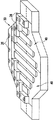
ここで図8を見ると、磁石単位11及び12の各々に対する永久磁石16の組み立てを表した図を示している。ここで、第1のブロック・アセンブリ62は、実質的に第1のレール42の遠位端で第1のブロック・アセンブリがリテーナ28に出会うまで第1のレール42に沿ってスライドさせることができる。その後、図9に示すように、第1のレール42によってキャビティ24の第1の部分として提供されるエリアがブロック・アセンブリ60によって完全に満たされるようになるまで、第2のブロック・アセンブリ64(さらに、必要に応じて後続のブロック・アセンブリ)を第1のレール42に沿ってスライドさせることができる。完成すると、第1のレール42の長さ方向のブロック・アセンブリ60の第1列71となる。図10を見ると、第1のブロック・アセンブリ62と第2のブロック・アセンブリ64(存在する場合はさらに後続のブロック・アセンブリ)とを包含し保持するようにリテーナ28が装着される。
Referring now to FIG. 8, a diagram illustrating the assembly of the
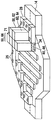
ここで図11を見ると、永久磁石16の組み立ての続きを表した図を示している。ここで、第3のブロック・アセンブリ66は、実質的に第2のレール44の遠位端で第3のブロック・アセンブリがリテーナ28に出会うまで第2のレール44に沿ってスライドさせることができる。その後、第2のレール44によってキャビティ24の第2の部分として提供されるエリアがブロック・アセンブリ60によって完全に満たされるようになるまで、第4のブロック・アセンブリ68(さらに、必要に応じて後続のブロック・アセンブリ)を第2のレール44に沿ってスライドさせることができる。第2のレール44の長さ方向でブロック・アセンブリ60の第2列72が完成すると図のようになる。図12を見ると、この後で第2のレール44上に装着したブロック・アセンブリ60(例えば、ブロック・アセンブリ66及び後続のブロック・アセンブリ)を包含し保持するようにリテーナ28が装着される。この場合も同様に、リテーナ28は、ねじやボルトなどの留め具26を用いて装着し取り付けることができる。
Here, when FIG. 11 is seen, the figure showing the continuation of the assembly of the
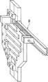
ここで図13を見ると、ほぼ完成間際の永久磁石16の組み立てを表した図を示している。図に示すように、第3列及び第4列のブロック・アセンブリ73及び74のそれぞれは、リテーナ28によって完成させかつ固定し終わっている。さらに、この図は組み立て及び固定の済んだ第8、第7及び第6の列78、77及び76のそれぞれも表している。この時点において、これらの図からリテーナ28は、最外側から最内側までの複数のレール40、したがって複数の列(例えば、71〜78)にまたがることができることは明らかであることに留意すべきである。したがって、組み立て及び据え付けを容易にするために、レール40を構成要素で満たす作業を最外側レール40で開始し中心に向かって移動することによって最も容易に達成することができる。本明細書では単に1つの例示的な組み立て手順を開示していることに留意すべきである。継鉄プレート14上でのレール40及びリテーナ28の選択した向きに応じて、別の手順も可能であり、またそう見込まれる。
Here, when FIG. 13 is seen, the figure showing the assembly of the
図13を見ると、ここで残りのレール40を満たすように追加的なブロック・アセンブリを追加し、実装させる最後の列にあたる第5列75を完成させる。図14は、ブロック・アセンブリ60を完全に実装させかつリテーナ28で固定した永久磁石16を表している。図15を参照すると、磁石単位11及び12の組み立てを完了するために、上側と下側の磁極片18を永久磁石16に係合させかつ固定することができる。この時点において、磁極片18のアセンブリは、磁石ブロック・アセンブリ60の全体的な挿入工程中において、米国特許第6,336,989号に記載するような位置決めや任意の位置とすることがあることに留意すべきである。磁極片18は組み立て工程を容易にする重要な役割をしているが、磁極片は必ずしも本開示と同じ方法で配列させる必要はない。
Referring to FIG. 13, additional block assemblies are now added to fill the remaining
ここで図17を見ると、ブロック・アセンブリ60を挿入するための例示的な一装置を表している。図示しているのは磁石ブロック押し込み工具100であって、選択したレール40上への個々のブロック・アセンブリ60のスライドを容易にするような方式によって磁石単位11及び12の各々と整列できるように構成した磁石ブロック押し込み工具100である。例示的な実施の一形態では、磁化させたブロック・アセンブリ60を挿入のために磁石ブロック押し込み工具100上に配置している。ブロック・アセンブリ60はレール40に沿って組立体の一部として容易にスライドできるが、なおかつ各磁石単位11、12に対する永久磁石16のブロック・アセンブリの組み立てアレイに関して望ましい許容誤差が保証される程度に十分にぴったりとはめ合わせるように構成できることを理解されたい。したがって、この組み立て工程は比較的容易でありかつ一般的である。磁石ブロック20/ブロック・アセンブリ60、レール40、リテーナ28、並びにその他の構成要素は、磁石単位11及び12に関する所望の組立体許容誤差を維持するためにブロック・アセンブリをレール40、グライダー34及びリテーナ28によって拘束させて必要に応じた正確さで配置することができる。さらに、グライダーと連携させるレールのレイアウトは図では磁石ブロック20に対する選択占有域の関数であるが、別の構成も容易に明らかであることを理解されたい。こうしたレイアウトでは永久磁石16の製造に必要な懸案を満足させるように多様な構成を利用する可能性がある。
Turning now to FIG. 17, an exemplary apparatus for inserting the
ブロック・アセンブリ60の各々は組み立て工程においてそれ自体の物理的拘束とレール40、グライダー34及びリテーナ28とによって固定されるため、個々のブロック・アセンブリ間に接着剤や結合を必要としないので有利である。この利点によって組み立て工程が極めて改善されると共に、磁石部材に対する将来的な修正、分解、システムのアップグレード、再加工、あるいはリサイクルが容易となる。恐らく、組立体においてもっと大きな許容誤差を使用することや、組立体を留めるために必要に応じて接着剤やエポキシを利用することなど、別の実施形態も利用することができる。
Each of the
接着剤の必要がないという例示的な実施の一形態のこの特徴は、磁石アセンブリの再加工が万一必要になった場合でもその再加工がこの特徴によって容易になるという点で大きな利点となる。磁石部材間に結合剤や接着剤を使用していないため、修正、修復、再加工または分解を要する場合には、開示した組み立て工程を実質的に逆転させ、分解工程を容易にすることができる。換言すると、万一損傷した磁石ブロック20/ブロック・アセンブリ60の除去を要する場合には、磁石ブロック20/ブロック・アセンブリ60同士の間、あるいは磁石ブロック20/ブロック・アセンブリ60とレール40や継鉄プレート14との間に接着剤を使用していないため、組み立て工程を本質的に逆転させることができる。損傷した磁石ブロック20/ブロック・アセンブリ60は容易に除去し、新しいものと交換する(例えば、磁極片18を持ち上げる、リテーナ28を除去する、磁石ブロック60を除去する、など)ことができる。
This feature of an exemplary embodiment in which no adhesive is required is a significant advantage in that this feature facilitates reworking of the magnet assembly should it become necessary. . Because no binder or adhesive is used between the magnet members, the disclosed assembly process can be substantially reversed to facilitate the disassembly process if correction, repair, rework or disassembly is required . In other words, if it is necessary to remove the damaged
上述の開示では、その磁石アセンブリの構成要素(ブロック・リテーナ28、留め具26、レール40、グライダー34、その他)が(必須ではないが)好ましくは継鉄プレート14と同じ強磁性体によって製造される可能性があるものとして記載した多く例を提供していることを理解されたい。非磁性の製造が有益であるような例も存在する場合がある。例えば、非磁性材料を使用すると、これらに対して相互作用する磁気力がないためある種の構成要素の実装が容易となることがある。こうした構成の1つでは、磁性材料との違いに対処するように追加的な磁石ブロック20の利用を要することがある。通常の非磁性材料としては、アルミニウム、ステンレス鋼、プラスチックG−10その他、並びにこれらの少なくとも1つを含む組み合わせを含むことができるが、これらに限るものではない。
In the above disclosure, the components of the magnet assembly (block
本発明に関して好ましい実施の一形態を参照しながら記載してきたが、本発明の趣旨を逸脱することなく様々な変更が可能であると共に、本発明の各要素は等価物により代用可能であることは当業者であれば理解するであろう。さらに、多くの修正形態により、本発明の本質的趣旨を逸脱することなく具体的な状況や素材を本発明の教示に適応させることができる。したがって、本発明を実行するように企図されたベストモードとして開示した具体的な実施形態に本発明を限定しようという意図ではなく、逆に本発明により、添付の特許請求の範囲の域内に入るすべての実施形態を包含させようとする意図である。さらに、第1(first)、第2(second)などの語の使用は順位や重要性をなんら示すものではなく、第1、第2などの語はある要素を別の要素と区別するために使用したものである。
Although the present invention has been described with reference to a preferred embodiment, various modifications can be made without departing from the spirit of the present invention, and each element of the present invention can be replaced by an equivalent. Those skilled in the art will understand. In addition, many modifications may be made to adapt specific situations and materials to the teachings of the invention without departing from the essential spirit thereof. Accordingly, it is not intended that the invention be limited to the specific embodiments disclosed as the best mode contemplated for practicing the invention, but on the contrary, the invention shall cover all that fall within the scope of the appended claims. It is intended to include the embodiments. Furthermore, the use of words such as first (first) and second (second) does not indicate ranking or importance, and the words such as first and second are for distinguishing one element from another. It is what was used.
10 磁場発生装置
11 上側磁石単位
12 下側磁石単位
14 継鉄プレート
16 永久磁石
18 磁極片
20 磁石ブロック
22 ポスト
24 キャビティ
26 留め具
28 リテーナ
30 リテーナの組
34 グライダー
36 スロット
40 レール
42 第1のレール
44 第2のレール
62 第1のブロック・アセンブリ
64 第2のブロック・アセンブリ
66 第3のブロック・アセンブリ
68 第4のブロック・アセンブリ
71 ブロック・アセンブリ第1列
72 ブロック・アセンブリ第2列
73 ブロック・アセンブリ第3列
74 ブロック・アセンブリ第4列
75 ブロック・アセンブリ第5列
76 ブロック・アセンブリ第6列
77 ブロック・アセンブリ第7列
78 ブロック・アセンブリ第8列
100 磁石ブロック押し込み工具
DESCRIPTION OF
Claims (8)
強磁性継鉄プレート(14)と永久磁石(16)を備える磁石アセンブリの永久磁石(16)の配列を確定させるステップであって、該配列は前記継鉄プレート(14)の実質的な外周位置に取り付けた複数のリテーナ(28)の一部分の配置によって形成されるキャビティ(24)の一部分を含むような配列確定のステップと、
前記キャビティ(24)の前記第1の部分内で、1組のレール(40)を前記継鉄プレート(14)に配置し固定するステップと、
複数の磁石ブロック(20)に複数のグライダー(34)を添着させ、該グライダー(34)及び磁石ブロック(20)を磁化させて複数のブロック・アセンブリ(60)を形成させるステップと、
前記複数のブロック・アセンブリ(60)を、前記レール組(40)の1つのレール(40)に沿ってスライドさせるステップと、
を含み、
前記レール(40)に沿った前記ブロック・アセンブリ(60)のスライドは、ブロック・アセンブリ(60)で各レールを充填し、最外側レール(40)で開始し最内側で終了し、連続して充填させる各レール(40)を前記継鉄プレート(14)に取り付けられたリテーナ(28)で固定するように行われる、方法。 A method of assembling a magnetic field generator (10) for a magnetic resonance imaging system comprising:
Determining the arrangement of permanent magnets (16) of a magnet assembly comprising a ferromagnetic yoke plate (14) and permanent magnets (16), the arrangement being a substantially peripheral position of said yoke plate (14); An alignment step including a portion of a cavity (24) formed by the placement of a portion of a plurality of retainers (28) attached to
Placing and securing a set of rails (40) to the yoke plate (14) within the first portion of the cavity (24);
Attaching a plurality of gliders (34) to a plurality of magnet blocks (20) and magnetizing the glider (34) and magnet blocks (20) to form a plurality of block assemblies (60);
A step of said plurality of block assemblies (60), Ru is slid along one of the rails (40) of said rail assembly (40),
Only including,
The slide of the block assembly (60) along the rail (40) fills each rail with the block assembly (60), starts at the outermost rail (40) and ends at the innermost, continuously. The method is performed such that each rail (40) to be filled is fixed by a retainer (28) attached to the yoke plate (14) .
強磁性継鉄プレート(14)と永久磁石(16)を備える磁石アセンブリの永久磁石(16)の配列であって、前記継鉄プレート(14)の実質的な外周位置に取り付けた複数のリテーナ(28)の一部分の配置によって形成されるキャビティ(24)の一部分を含むような永久磁石配列と、
前記キャビティ(24)の前記第1の部分内に配置され、前記継鉄プレート(14)に取り付けられた1組のレール(40)と、
複数の磁石ブロック(20)に添着させると共に、複数のブロック・アセンブリ(60)を形成させるように磁化させた複数のグライダー(34)と、を備えると共に、
前記複数のブロック・アセンブリ(60)の各ブロック・アセンブリ(60)は、前記レール組(40)の1つのレール(40)に沿ってスライドし、
前記ブロック・アセンブリ(60)は、ブロック・アセンブリ(60)で各レールを充填し、最外側レール(40)で開始し最内側で終了し、連続して充填させる各レール(40)を前記継鉄プレート(14)に取り付けられたリテーナ(28)で固定するようにスライドする、磁場発生装置(10)。 A magnetic field generator (10) for a magnetic resonance imaging system comprising:
An array of permanent magnets (16) of a magnet assembly comprising a ferromagnetic yoke plate (14) and permanent magnets (16), wherein a plurality of retainers attached to a substantially outer peripheral position of the yoke plate (14) A permanent magnet array including a portion of the cavity (24) formed by the arrangement of a portion of 28);
Wherein disposed on the first portion of the cavity (24), and said yoke plate set of rails attached to the (14) (40),
A plurality of gliders (34) attached to a plurality of magnet blocks (20) and magnetized to form a plurality of block assemblies (60);
Each of the plurality of block assembly of the block assembly (60) (60) slides along the one rail (40) of said rail assembly (40),
The block assembly (60) fills each rail with the block assembly (60), starts with the outermost rail (40), ends with the innermost rail, and continuously connects each rail (40) to be filled. A magnetic field generator (10) that slides to be fixed by a retainer (28) attached to an iron plate (14 ).
Applications Claiming Priority (1)
| Application Number | Priority Date | Filing Date | Title |
|---|---|---|---|
| US10/064,565 US6664878B1 (en) | 2002-07-26 | 2002-07-26 | Method for assembling magnetic members for magnetic resonance imaging magnetic field generator |
Publications (3)
| Publication Number | Publication Date |
|---|---|
| JP2004057829A JP2004057829A (en) | 2004-02-26 |
| JP2004057829A5 JP2004057829A5 (en) | 2008-09-11 |
| JP4344882B2 true JP4344882B2 (en) | 2009-10-14 |
Family
ID=29709246
Family Applications (1)
| Application Number | Title | Priority Date | Filing Date |
|---|---|---|---|
| JP2003279515A Expired - Fee Related JP4344882B2 (en) | 2002-07-26 | 2003-07-25 | Method for assembling a magnetic member for a magnetic resonance imaging magnetic field generator |
Country Status (6)
| Country | Link |
|---|---|
| US (1) | US6664878B1 (en) |
| EP (1) | EP1385017B1 (en) |
| JP (1) | JP4344882B2 (en) |
| KR (1) | KR20040010393A (en) |
| CN (1) | CN100337585C (en) |
| DE (1) | DE60323573D1 (en) |
Cited By (1)
| Publication number | Priority date | Publication date | Assignee | Title |
|---|---|---|---|---|
| JP7282270B2 (en) | 2020-06-30 | 2023-05-26 | 古河電気工業株式会社 | LASER CUTTING METHOD AND LASER CUTTING APPARATUS FOR METAL FOIL |
Families Citing this family (14)
| Publication number | Priority date | Publication date | Assignee | Title |
|---|---|---|---|---|
| US6859123B2 (en) * | 2003-04-03 | 2005-02-22 | Ge Medical Systems Global Technology Company, Llc | Methods and apparatus for positioning permanent magnetic blocks |
| US7373716B2 (en) * | 2003-10-22 | 2008-05-20 | Dexter Magnetic Technologies, Inc. | Method for constructing permanent magnet assemblies |
| WO2005088330A1 (en) * | 2004-03-03 | 2005-09-22 | Koninklijke Philips Electronics, N.V. | Asymmetric ultra-short gradient coil for magnetic resonance imaging system |
| US7631411B2 (en) * | 2004-06-28 | 2009-12-15 | General Electric Company | Method of manufacturing support structure for open MRI |
| US6958672B1 (en) * | 2004-06-30 | 2005-10-25 | General Electric Company | System and method for magnetizing blocks on a magnet assembly of an MRI device |
| CN101031238B (en) * | 2004-09-30 | 2010-07-28 | 日立金属株式会社 | Magnet field generator for MRI |
| US20060078844A1 (en) * | 2004-10-07 | 2006-04-13 | Goldman Paul D | Oral care systems, oral care devices and methods of use |
| GB2436364B (en) * | 2006-03-21 | 2008-07-02 | Siemens Magnet Technology Ltd | Apparatus for shimming a magnetic field |
| GB2436365B (en) * | 2006-03-21 | 2008-04-02 | Siemens Magnet Technology Ltd | Apparatus and method for shimming the magnetic field generated by a magnet |
| US8674797B2 (en) * | 2009-02-27 | 2014-03-18 | Hitachi Metals, Ltd. | Magnetic field generator |
| CN104931902A (en) * | 2015-06-30 | 2015-09-23 | 东南大学 | Apparatus for integrating nuclear magnetic resonance magnet with probe |
| JP6407825B2 (en) * | 2015-09-02 | 2018-10-17 | 信越化学工業株式会社 | Method for manufacturing permanent magnet magnetic circuit |
| US10847294B2 (en) * | 2017-07-10 | 2020-11-24 | Aspect Imaging Ltd. | System for generating a magnetic field |
| CN109669150A (en) * | 2018-12-29 | 2019-04-23 | 佛山瑞加图医疗科技有限公司 | A kind of circumference magnet installation special equipment and installation method |
Family Cites Families (13)
| Publication number | Priority date | Publication date | Assignee | Title |
|---|---|---|---|---|
| CA1316375C (en) | 1982-08-21 | 1993-04-20 | Masato Sagawa | Magnetic materials and permanent magnets |
| US4931760A (en) | 1986-10-08 | 1990-06-05 | Asahi Kasei Kogyo Kabushiki Kaisha | Uniform magnetic field generator |
| GB8825529D0 (en) | 1988-11-01 | 1988-12-07 | Oxford Magnet Tech | Magnetic field generating assembly |
| GB9105286D0 (en) | 1991-03-13 | 1991-04-24 | Oxford Instr Ltd | Magnetic field generating apparatus |
| JPH0669027A (en) | 1991-10-24 | 1994-03-11 | Hitachi Ltd | Magnetic field generation device |
| JP2699250B2 (en) | 1993-01-22 | 1998-01-19 | 信越化学工業株式会社 | Magnetic field generator and method of manufacturing magnetic field generator |
| US6794973B1 (en) | 1998-04-14 | 2004-09-21 | Sumitomo Special Metals Co., Ltd. | Magnetic field generating device for MRI |
| JP2953659B1 (en) | 1998-08-06 | 1999-09-27 | 住友特殊金属株式会社 | Magnetic field generator for MRI, method of assembling the same, and method of assembling magnet unit used therein |
| JP2000139874A (en) | 1998-09-02 | 2000-05-23 | Sumitomo Special Metals Co Ltd | Magnetic field generator for mri |
| CN1159576C (en) * | 1999-05-10 | 2004-07-28 | 三星电子株式会社 | Method for producing master magnet body assembly for magnetic resonance imaging system |
| EP1666910B1 (en) * | 1999-11-16 | 2009-03-11 | Hitachi Metals, Ltd. | Magnetic-field generator comprising a pole-piece unit |
| JP4135127B2 (en) * | 2000-04-21 | 2008-08-20 | 信越化学工業株式会社 | Assembly method of magnetic field generator |
| JP3788573B2 (en) * | 2000-11-16 | 2006-06-21 | 信越化学工業株式会社 | MRI magnetic circuit assembly method |
-
2002
- 2002-07-26 US US10/064,565 patent/US6664878B1/en not_active Expired - Lifetime
-
2003
- 2003-07-18 EP EP03254498A patent/EP1385017B1/en not_active Expired - Fee Related
- 2003-07-18 DE DE60323573T patent/DE60323573D1/en not_active Expired - Lifetime
- 2003-07-25 KR KR1020030051363A patent/KR20040010393A/en active IP Right Grant
- 2003-07-25 JP JP2003279515A patent/JP4344882B2/en not_active Expired - Fee Related
- 2003-07-28 CN CNB031436366A patent/CN100337585C/en not_active Expired - Fee Related
Cited By (1)
| Publication number | Priority date | Publication date | Assignee | Title |
|---|---|---|---|---|
| JP7282270B2 (en) | 2020-06-30 | 2023-05-26 | 古河電気工業株式会社 | LASER CUTTING METHOD AND LASER CUTTING APPARATUS FOR METAL FOIL |
Also Published As
| Publication number | Publication date |
|---|---|
| EP1385017A1 (en) | 2004-01-28 |
| DE60323573D1 (en) | 2008-10-30 |
| KR20040010393A (en) | 2004-01-31 |
| JP2004057829A (en) | 2004-02-26 |
| CN100337585C (en) | 2007-09-19 |
| US6664878B1 (en) | 2003-12-16 |
| EP1385017B1 (en) | 2008-09-17 |
| CN1491613A (en) | 2004-04-28 |
Similar Documents
| Publication | Publication Date | Title |
|---|---|---|
| JP4344882B2 (en) | Method for assembling a magnetic member for a magnetic resonance imaging magnetic field generator | |
| CN205159023U (en) | Magnet unit | |
| WO2005124979A1 (en) | Linear motor and method of producing linear motor | |
| WO2011048652A1 (en) | Magnetizing device and method for manufacturing permanent magnet motor | |
| CN101086524A (en) | Method for disassembling a magnetic field generator | |
| JP2004057829A5 (en) | ||
| EP1605574A1 (en) | Rotor for synchronous motor | |
| JP4370247B2 (en) | Method for assembling a magnetic member for a magnetic field generator for magnetic resonance imaging | |
| JPH08339916A (en) | Permanent-magnet magnetic circuit | |
| CN105280324B (en) | The manufacturing method of magnet unit and magnet unit | |
| US9589722B2 (en) | Method of producing a cylindrical magnetic circuit | |
| JPWO2005124980A1 (en) | Manufacturing method of linear motor | |
| EP1238399A1 (en) | Method for producing and magazining individual magnetic components and the assembly thereof for producing miniaturised magnetic systems and such magnetic systems | |
| CN105989985B (en) | Magnet, pickup device using the same, and method for manufacturing the same | |
| JP4494883B2 (en) | Rotor manufacturing method and apparatus | |
| JPS6373861A (en) | Manufacture of magnet circuit | |
| JP2006304447A (en) | Linear motor and permanent magnet fixing device | |
| JPH08275420A (en) | Method for assembling magnetic circuit and its magnetic pole magnet | |
| JP2003347121A (en) | Method for manufacturing periodic magnetic-field generation magnetic circuit and assembling jig | |
| US7001479B2 (en) | Methods and apparatus for assembling magnetized permanent magnetic blocks | |
| JP2006060948A (en) | Magnetic circuit and manufacturing method therefor | |
| CN116721829A (en) | Halbach array magnet and preparation method thereof | |
| JPH01238103A (en) | Magnet device and manufacture thereof | |
| JPH0525978U (en) | Voice coil motor | |
| JPS62185549A (en) | Manufacture of magnetic circuit |
Legal Events
| Date | Code | Title | Description |
|---|---|---|---|
| A521 | Written amendment |
Free format text: JAPANESE INTERMEDIATE CODE: A523 Effective date: 20060720 |
|
| A621 | Written request for application examination |
Free format text: JAPANESE INTERMEDIATE CODE: A621 Effective date: 20060720 |
|
| A521 | Written amendment |
Free format text: JAPANESE INTERMEDIATE CODE: A523 Effective date: 20080730 |
|
| A977 | Report on retrieval |
Free format text: JAPANESE INTERMEDIATE CODE: A971007 Effective date: 20090521 |
|
| TRDD | Decision of grant or rejection written | ||
| A01 | Written decision to grant a patent or to grant a registration (utility model) |
Free format text: JAPANESE INTERMEDIATE CODE: A01 Effective date: 20090602 |
|
| A01 | Written decision to grant a patent or to grant a registration (utility model) |
Free format text: JAPANESE INTERMEDIATE CODE: A01 |
|
| RD02 | Notification of acceptance of power of attorney |
Free format text: JAPANESE INTERMEDIATE CODE: A7422 Effective date: 20090629 |
|
| RD04 | Notification of resignation of power of attorney |
Free format text: JAPANESE INTERMEDIATE CODE: A7424 Effective date: 20090629 |
|
| A61 | First payment of annual fees (during grant procedure) |
Free format text: JAPANESE INTERMEDIATE CODE: A61 Effective date: 20090629 |
|
| A521 | Written amendment |
Free format text: JAPANESE INTERMEDIATE CODE: A523 Effective date: 20090713 |
|
| R150 | Certificate of patent or registration of utility model |
Free format text: JAPANESE INTERMEDIATE CODE: R150 |
|
| FPAY | Renewal fee payment (event date is renewal date of database) |
Free format text: PAYMENT UNTIL: 20120724 Year of fee payment: 3 |
|
| FPAY | Renewal fee payment (event date is renewal date of database) |
Free format text: PAYMENT UNTIL: 20120724 Year of fee payment: 3 |
|
| FPAY | Renewal fee payment (event date is renewal date of database) |
Free format text: PAYMENT UNTIL: 20130724 Year of fee payment: 4 |
|
| R250 | Receipt of annual fees |
Free format text: JAPANESE INTERMEDIATE CODE: R250 |
|
| R250 | Receipt of annual fees |
Free format text: JAPANESE INTERMEDIATE CODE: R250 |
|
| R250 | Receipt of annual fees |
Free format text: JAPANESE INTERMEDIATE CODE: R250 |
|
| R250 | Receipt of annual fees |
Free format text: JAPANESE INTERMEDIATE CODE: R250 |
|
| LAPS | Cancellation because of no payment of annual fees |