JP4342348B2 - Combined variable frequency silencer system - Google Patents
Combined variable frequency silencer system Download PDFInfo
- Publication number
- JP4342348B2 JP4342348B2 JP2004067134A JP2004067134A JP4342348B2 JP 4342348 B2 JP4342348 B2 JP 4342348B2 JP 2004067134 A JP2004067134 A JP 2004067134A JP 2004067134 A JP2004067134 A JP 2004067134A JP 4342348 B2 JP4342348 B2 JP 4342348B2
- Authority
- JP
- Japan
- Prior art keywords
- frequency
- fixed
- resonator
- neck wall
- variable
- Prior art date
- Legal status (The legal status is an assumption and is not a legal conclusion. Google has not performed a legal analysis and makes no representation as to the accuracy of the status listed.)
- Expired - Fee Related
Links
Images


Description
本発明は、車両用エンジンの回転数に応じて発生変化するエンジン吸気系騒音をエンジン回転数検出装置・演算処理装置・可変周波数共鳴型レゾネータ装置により回転数に応じて所望の騒音周波数を選択的に消音する可変周波数消音システム(装置)に関する。 The present invention selectively selects a desired noise frequency according to the rotational speed of an engine intake system noise generated and changed according to the rotational speed of a vehicle engine by means of an engine rotational speed detection device, an arithmetic processing device, and a variable frequency resonance type resonator device. The present invention relates to a variable frequency silencing system (device) for silencing sound.
自動車のエンジンの吸気系には、レゾネータと呼ばれる共鳴型の消音器が装着される。しかし、共鳴型消音器は一つの周波数しか消音することができないため消音したい周波数が複数ある場合、消音器が複数個必要となる。そこで、部品点数、スペースといった欠点を補うために、エンジン回転数あるいは車両速度に応じて消音周波数を可変させる可変周波数共鳴型レゾネータ装置が考えられており、その可変構造は数多く提案されている(たとえば、特許文献1〜12)。 A resonance muffler called a resonator is mounted on the intake system of an automobile engine. However, since the resonance muffler can mute only one frequency, if there are a plurality of frequencies to be muffled, a plurality of mufflers are required. Therefore, in order to compensate for the drawbacks such as the number of parts and the space, a variable frequency resonance type resonator device that varies the muffling frequency according to the engine speed or the vehicle speed has been considered, and many variable structures have been proposed (for example, And Patent Documents 1 to 12).
従来の可変周波数共鳴型レゾネータ装置には、つぎの問題点がある。
吸気騒音の主成分は、エンジン回転数に同期し周波数が変化する騒音(回転次数成分)とエンジン回転数とは無関係に常に一定の周波数で発生する騒音(気柱共鳴)の2つがあげられる。しかし、従来の可変周波数共鳴型レゾネータ装置では、エンジン回転数あるいは車両速度に応じて、所望の単一の騒音周波数を消音するのみであり、どちらか一方しか消音できず、結果的に全体での騒音レベルが期待ほど大きく得られない。
There are two main components of the intake noise: noise that changes in frequency in synchronization with the engine speed (rotational order component) and noise that always occurs at a constant frequency (air column resonance) regardless of the engine speed. However, in the conventional variable frequency resonance type resonator device, only a desired single noise frequency is silenced according to the engine speed or the vehicle speed, and only one of them can be silenced. The noise level is not as great as expected.
本発明が解決しようとする問題点は、回転次数成分と気柱共鳴のどちらか一方しか消音できないことである。
本発明の目的は、エンジン回転数と同期し周波数が変化する騒音(回転次数成分)を消音するとともに、常に一定の周波数で発生する騒音(気柱共鳴)を同時に消音できる複合型可変周波数消音システムを提供することにある。
The problem to be solved by the present invention is that only one of the rotational order component and air column resonance can be silenced.
An object of the present invention is to provide a composite variable frequency silencing system capable of silencing noise (rotational order component) whose frequency changes in synchronization with the engine speed and simultaneously silencing noise (air column resonance) generated at a constant frequency at the same time. Is to provide.
上記目的を達成する本発明はつぎの通りである。
(1) 車両用エンジン回転数に応じて発生変化するエンジン吸気系騒音をエンジン回転数検出装置と演算処理装置と可変周波数共鳴型レゾネータ装置により回転数に応じて所望の騒音周波数を選択的に消音する複合型可変周波数消音システムであって、
前記可変周波数共鳴型レゾネータ装置が、(a)共鳴部と固定首壁と該固定首壁内に可動状態に配置された部材とを備え該部材により前記固定首壁の断面積が変更されるとともに前記部材自体が周波数固定レゾネータとして構成される周波数可変レゾネータと、(b)前記周波数固定レゾネータを駆動する駆動アクチュエータと、(c)前記周波数固定レゾネータの位置を検出する位置検出部を有する、複合型可変周波数消音システム。
(2) 前記周波数固定レゾネータは、前記固定首壁とともに周波数可変レゾネータの首壁を構成する(1)記載の複合型可変周波数消音システム。
(3) 前記固定首壁と前記周波数固定レゾネータは、前記周波数可変レゾネータの共鳴部内に配置されている、(1)記載の複合型可変周波数消音システム。
(4) 前記周波数固定レゾネータは、前記固定首壁に対して回動可能とされている(1)記載の複合型可変周波数消音システム。
(5) 前記周波数固定レゾネータは、前記固定首壁に対して直線動可能とされている(1)記載の複合型可変周波数消音システム。
The present invention for achieving the above object is as follows.
(1) A desired noise frequency is selectively silenced according to the number of revolutions of the engine intake system noise generated and changed according to the engine speed of the vehicle by means of an engine speed detection device, an arithmetic processing unit, and a variable frequency resonance type resonator device. A combined variable frequency silencer system,
The variable frequency resonance type resonator device includes: (a) a resonance part , a fixed neck wall , and a member arranged in a movable state in the fixed neck wall; and the cross-sectional area of the fixed neck wall is changed by the member. A composite type having a frequency variable resonator configured as a frequency fixed resonator, the member itself , (b) a drive actuator that drives the frequency fixed resonator, and (c) a position detection unit that detects the position of the frequency fixed resonator. Variable frequency silencer system.
(2) The composite variable frequency silencing system according to (1), wherein the fixed frequency resonator constitutes a neck wall of a variable frequency resonator together with the fixed neck wall.
(3) The composite variable frequency silencer system according to (1), wherein the fixed neck wall and the frequency fixed resonator are arranged in a resonance portion of the frequency variable resonator.
(4) The composite variable frequency silencer system according to (1), wherein the fixed frequency resonator is rotatable with respect to the fixed neck wall.
(5) The composite variable frequency silencer system according to (1), wherein the fixed frequency resonator is linearly movable with respect to the fixed neck wall.
上記(1)の複合型可変周波数消音システムでは、可変周波数共鳴型レゾネータ装置が周波数固定レゾネータを有するので、エンジン回転数とは無関係に常に一定の周波数で発生する騒音(気柱共鳴)を周波数固定レゾネータで消音できる。また、可変周波数共鳴型レゾネータ装置が固定首壁と可動の周波数固定レゾネータを有するので、固定首壁に対して周波数固定レゾネータを動かすことにより、エンジン回転数と同期し周波数が変化する騒音(回転次数成分)を消音できる。したがって、2つの周波数を同時に消音することができる。
上記(2)の複合型可変周波数消音システムでは、周波数固定レゾネータを構成する壁の一部が固定首壁とともに周波数可変レゾネータの首壁を構成する。
上記(3)の複合型可変周波数消音システムでは、周波数固定レゾネータが固定首壁に対して動くと、周波数固定レゾネータが共鳴部内で固定首壁が囲むスペースに入り込む量が変化する。そのため、周波数可変レゾネータの首部断面積が小さくなるにつれて(大きくなるにつれて)周波数可変レゾネータの容積は逆に大きくなる(小さくなる)。したがって、首部断面積だけあるいは容積だけを可変とする場合に比べて、消音周波数の可変幅が大きく、所望の消音周波数に素早く応答することができる。
上記(4)の複合型可変周波数消音システムでは、周波数固定レゾネータを回転させることで周波数可変レゾネータの首部断面積を変えることができる。そのため、複数個の首部形状は不要である。そのため、複数個の首部形状を持つ場合に比べて、省スペース化をはかることができる。
上記(5)の複合型可変周波数消音システムでは、周波数固定レゾネータを直線動させることで周波数可変レゾネータの首部断面積を変えることができる。そのため、複数個の首部形状は不要である。そのため、複数個の首部形状を持つ場合に比べて、省スペース化をはかることができる。
In the composite type variable frequency silencer system of (1) above, the variable frequency resonance type resonator device has a fixed frequency resonator, so that noise (air column resonance) that is always generated at a constant frequency is fixed regardless of the engine speed. Can be muted with a resonator. In addition, since the variable frequency resonance type resonator device has a fixed neck wall and a movable frequency fixed resonator, by moving the frequency fixed resonator with respect to the fixed neck wall, noise that changes in frequency in synchronization with the engine speed (rotation order) Component) can be muted. Therefore, it is possible to mute two frequencies simultaneously.
In the composite variable frequency silencer system of (2) above, a part of the wall constituting the frequency fixed resonator constitutes the neck wall of the frequency variable resonator together with the fixed neck wall.
In the composite variable frequency silencer system of (3) above, when the frequency fixed resonator moves relative to the fixed neck wall, the amount of the frequency fixed resonator entering the space surrounded by the fixed neck wall in the resonance portion changes. Therefore, as the neck cross-sectional area of the frequency variable resonator decreases (increases), the volume of the frequency variable resonator increases (decreases). Therefore, compared with the case where only the neck cross-sectional area or only the volume is variable, the variable range of the silencing frequency is large, and it is possible to quickly respond to the desired silencing frequency.
In the composite variable frequency silencer system of (4), the neck cross-sectional area of the frequency variable resonator can be changed by rotating the frequency fixed resonator. Therefore, a plurality of neck shapes are not necessary. Therefore, space saving can be achieved compared with the case of having a plurality of neck shapes.
In the composite variable frequency silencer system of (5) above, the neck cross-sectional area of the frequency variable resonator can be changed by linearly moving the frequency fixed resonator. Therefore, a plurality of neck shapes are not necessary. Therefore, space saving can be achieved compared with the case of having a plurality of neck shapes.
図1〜図7は、本発明実施例1の複合型可変周波数消音システムを示しており、図8〜図10は、本発明実施例2の複合型可変周波数消音システムを示している。ただし、図1は、本発明実施例2にも適用可能である。
本発明実施例1と本発明実施例2にわたって共通する部分には、本発明実施例1と本発明実施例2にわたって共通する符号を付してある。
まず、本発明実施例1と本発明実施例2にわたって共通する部分を、たとえば、図1〜図3、図8を参照して、説明する。
本発明実施例の可変周波数消音システム(装置)10は、図1、図2に示すように、車両用エンジン回転数に応じて発生変化するエンジン吸気系騒音をエンジン回転数検出装置20と演算処理装置30と可変周波数共鳴型レゾネータ装置40によりエンジン回転数に応じて所望の騒音周波数を選択的に消音する可変周波数消音システムである。
FIGS. 1-7 has shown the composite type variable frequency silencer system of Example 1 of this invention, and FIGS. 8-10 has shown the composite type variable frequency silencer system of Example 2 of this invention. However, FIG. 1 is also applicable to the second embodiment of the present invention.
Parts common to the first embodiment of the present invention and the second embodiment of the present invention are denoted by the same reference numerals throughout the first embodiment of the present invention and the second embodiment of the present invention.
First, parts common to the first embodiment of the present invention and the second embodiment of the present invention will be described with reference to FIGS. 1 to 3 and FIG. 8, for example.
As shown in FIGS. 1 and 2, the variable frequency silencing system (apparatus) 10 according to the embodiment of the present invention is configured to calculate engine intake system noise generated and changed in accordance with the engine speed of the vehicle and the engine
可変周波数共鳴型レゾネータ装置40は、共鳴部42と固定首壁43と固定首壁43に対して可動な周波数固定レゾネータ44とを備える周波数可変レゾネータ41と、周波数固定レゾネータ44を駆動する駆動アクチュエータ(モーター)45と、周波数固定レゾネータ44の位置を検出する位置検出部46とを、有する。
The variable frequency resonance
共鳴部42は、エンジン吸気系の管路の途中に装着される。共鳴部42は、図2に示すように、内部に共鳴室を有する。共鳴部42の一壁には、エンジン吸気系とつながる開口42aが形成されている。
固定首壁43は、共鳴部42内に位置する。固定首壁43は、共鳴部42に固定されている。固定首壁43は、周波数可変レゾネータ41の首部の一部を構成する。
The
The
周波数固定レゾネータ44は、共鳴部42内に位置する。周波数固定レゾネータ44は、固定首壁43に対して移動可能である。ここで、移動は、回転動であってもよく、直線動(スライド)であってもよい。
周波数固定レゾネータ44が固定首壁43に対して図3(または図8)の矢印方向に動くと、共鳴部42の開口42aの大きさが変化する。そのため、周波数固定レゾネータ44が固定首壁43に対して動くと、周波数可変レゾネータ41の首部断面積が変化する。
周波数固定レゾネータ44は、内部に空間(共鳴室)を有しており、エンジン吸気系とつながる穴44aと、穴44aの縁から周波数固定レゾネータ44内側に延びる延び部44bを、有する。穴44aと延び部44bとで、周波数固定レゾネータ44の首部を構成する。周波数固定レゾネータ44の、首部断面積と首部長さと共鳴室は、一定である。
周波数固定レゾネータ44は、周波数可変レゾネータ41の首部の一部を構成する。周波数固定レゾネータ44と固定首壁43とで、周波数可変レゾネータ41の首部を構成する。
The
When the
The frequency fixed
The
駆動アクチュエータ45は、モーターからなる。モーターは、周波数固定レゾネータ44を動かす。駆動アクチュエータ45は、演算処理装置30からの信号に基づいて、周波数固定レゾネータ44を動かす。
位置検出部46は、周波数固定レゾネータ44の位置を検出しその信号を演算処理装置30にフィードバックする。
The
The
ここで、本発明実施例1と本発明実施例2にわたって共通する部分の作用を説明する。 図1に示すように、回転数検出装置20がエンジン50の回転数を検出し、その信号を演算処理装置30に送る。また、位置検出部46が周波数固定レゾネータ44の位置(回転角)を検出しその信号を演算処理装置30にフィードバックする。演算処理装置30は、位置検出部46からの信号に基づき周波数固定レゾネータ44の位置(回転角)を決め、その位置と位置検出部46で検出された周波数固定レゾネータ44の位置(移動前の位置)との差分を決め、駆動アクチュエータ45をどれだけ動かすかを決める。駆動アクチュエータ45(モーター)は、演算処理装置30からの信号に基づいて回転する。モーターが回転することにより周波数固定レゾネータ44が動く。
周波数固定レゾネータ44が移動し周波数固定レゾネータ44の位置が狙い値まできたとき、演算処理装置30がモーター停止信号を駆動アクチュエータ45に出力し、その信号に基づいてモーターが止まる。モーターが止まるため周波数固定レゾネータ44の移動が止まる。
周波数固定レゾネータ44の位置が狙い値にあるとき、周波数可変レゾネータ41は所望の騒音周波数を消音する。また、周波数固定レゾネータ44の位置が狙い値にあるとき、周波数固定レゾネータ44の穴44aが開口42aに重なっており、周波数固定レゾネータ44は一定の周波数で発生する騒音を消音する。
Here, an operation of a part common to the first embodiment of the present invention and the second embodiment of the present invention will be described. As shown in FIG. 1, the rotational
When the fixed
When the position of the fixed
図3、図8に示すように、可変周波数共鳴型レゾネータ装置40が周波数固定レゾネータ44を有するので、エンジン回転数とは無関係に常に一定の周波数で発生する騒音(気柱共鳴)を周波数固定レゾネータ44で消音できる。また、周波数固定レゾネータ44と固定首壁43とで周波数可変レゾネータ41の首部を構成するので、周波数固定レゾネータ44が固定首壁43に対して動くことによりエンジン回転数と同期し周波数が変化する騒音(回転次数成分)を消音できる。したがって、2つの周波数を同時に消音することができる。
As shown in FIGS. 3 and 8, since the variable frequency resonance
消音周波数と音速と首部長さと容積と首部断面積との関係は、(a)式で表される。
f=(c/2π){S/(L・V)}1/2・・・・・(a)
ただし、
f(Hz):消音周波数
c:音速
L:首部長さ
V:容積
S:首部断面積
である。
本発明実施例では、周波数固定レゾネータ44が固定首壁43に対して動くと、固定首壁43が共鳴部42内で囲むスペースに周波数固定レゾネータ44が入り込む量が変化する。そのため、周波数可変レゾネータ41の首部断面積が小さくなるにつれて(大きくなるにつれて)、周波数可変レゾネータ41の共鳴部42の容積は逆に大きくなる(小さくなる)。すなわち、上記(a)式の右辺の分子が小さくなるにつれて(大きくなるにつれて)、上記(a)式の右辺の分母が逆に大きくなる(小さくなる)。したがって、首部断面積だけあるいは容積だけを可変とする場合に比べて、消音周波数の可変幅が大きく、所望の消音周波数に素早く応答することができる。
The relationship among the muffling frequency, the sound speed, the neck length, the volume, and the neck cross-sectional area is expressed by equation (a).
f = (c / 2π) {S / (L · V)} 1/2 (a)
However,
f (Hz): muffling frequency c: sound velocity L: neck length V: volume S: neck cross-sectional area.
In the embodiment of the present invention, when the fixed
周波数固定レゾネータ44を移動させることで周波数可変レゾネータ41の首部断面積と容積を変更できるので、首部断面積と容積の2つで消音周波数を変えることができる。そのため、首部断面積、首部長さ、容積のいずれか1つのみで消音周波数を変える場合に比べて、消音周波数の可変幅が大きい。消音周波数の可変幅が大きいので、周波数固定レゾネータ44を移動させる量が少なくても消音周波数の可変幅が大きく、モーターを回転させるだけで所望の消音周波数に素早く応答することができる。
また、周波数固定レゾネータ44を移動させることで首部断面積と容積を変えることができるので、複数個の首部形状は不要である。そのため、複数個の首部形状を持つ場合に比べて、省スペース化をはかることができる。
Since the neck cross-sectional area and volume of the
Further, since the neck cross-sectional area and the volume can be changed by moving the frequency fixed
つぎに、本発明各実施例に特有な部分を説明する。
[本発明実施例1](図1〜図7)
本発明実施例1では、周波数固定レゾネータ44が固定首壁43に対して回転動可能とされている場合を示している。
Next, parts unique to each embodiment of the present invention will be described.
[Invention Example 1] (FIGS. 1 to 7)
In the first embodiment of the present invention, a case where the fixed
共鳴部42の開口42aは、図2、図3に示すように、中心Pを中心とする半円形状である。
固定首壁43は、図3、図4に示すように、固定首壁A43aと、固定首壁B43bとを、有する。
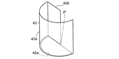
固定首壁A43aの形状は、中心Pを中心とする半円筒形状である。固定首壁A43aは、開口42aの半径方向外側端(開口42aの円弧状の縁全体)に固定して設けられている。
固定首壁B43bの形状は、平板形状である。固定首壁B43bは、固定首壁A43aと一体に形成されるか、または、固定首壁A43aと別体に形成されて固定首壁A43aに固定して取付けられる。固定首壁B43bは、半円筒形状の固定首壁A43aの周方向一辺から、固定首壁A43aの半径方向に中心Pまで延びている。
As shown in FIGS. 2 and 3, the opening 42 a of the
As shown in FIGS. 3 and 4, the fixed
The shape of the fixed neck wall A43a is a semi-cylindrical shape with the center P as the center. The fixed neck wall A43a is fixed to the radially outer end of the
The shape of the fixed neck wall B43b is a flat plate shape. The fixed neck wall B43b is formed integrally with the fixed neck wall A43a, or is formed separately from the fixed neck wall A43a and fixedly attached to the fixed neck wall A43a. The fixed neck wall B43b extends from one side in the circumferential direction of the semi-cylindrical fixed neck wall A43a to the center P in the radial direction of the fixed neck wall A43a.
周波数固定レゾネータ44は、中心Pまわりに固定首壁43に対して回転可能である。周波数固定レゾネータ44は、図2に示すように、駆動アクチュエータ45と、回動軸45aで結合している。
周波数固定レゾネータ44は、図3、図5に示すように、円筒部44cと、第1、第2の半円部44d、44eと、平板部44fとを、有する。
円筒部44cは、中心Pを中心とする半円筒形状である。
第1の半円部44dは、円筒部44cの軸方向一端(開口42a側端)に配置されている。第1の半円部44dは、開口42aと同じ(ほぼ同じを含む)形状であり、中心Pを中心とする半円状である。第1の半円部44dが開口42aと同じ形状であるので、周波数固定レゾネータ44が中心Pまわりに回転する角度が増えるにつれて、開口42aの大きさが小さくなる。穴44aは、第1の半円部44dに設けられている。
The fixed
As shown in FIGS. 3 and 5, the frequency fixed
The
The first
第2の半円部44eは、円筒部44cの軸方向他端に配置されている。第2の半円部44eは、開口42aと同じ(またはほぼ同じ)形状であり、中心Pを中心とする半円状である。
平板部44fは、円筒部44cと第1の半円部44dと第2の半円部44eとで形成される空間の開口を塞ぐ。
円筒部44cと第1の半円部44dと第2の半円部44eと平板部44fとで囲まれる空間から、穴44aと延び部44bとで構成される首部部分を除いた部分が、周波数固定レゾネータ44の共鳴室である。
The second
The
The portion excluding the neck portion composed of the
本発明実施例1の作用、効果を説明する。
周波数固定レゾネータ44が固定首壁43に対して回転する角度が増えると、開口42aが小さくなる。そのため、周波数可変レゾネータ41の首部断面積が小さくなる。
ここで、図6に示すような吸気系に見立てた管路60の途中に可変周波数共鳴型レゾネータ装置40を装着し、周波数固定レゾネータ44を固定首壁43に対して軸芯Pまわりに図3の矢印方向に回転させたときにおける3パターン(回転角20°、回転角70°、回転角120°)位置の消音周波数を図7に示す。図7に示すように、角度が変わることで周波数可変レゾネータ41の首部断面積と容積が変わり、消音周波数を可変させることができる。また、周波数固定レゾネータ44を有するので、周波数固定レゾネータ44でエンジン回転数とは無関係に常に一定の周波数で発生する騒音(気柱共鳴)を消音できる。
The operation and effect of Embodiment 1 of the present invention will be described.
As the angle at which the
Here, the variable frequency resonance
[本発明実施例2](図8〜図10)
本発明実施例2では、周波数固定レゾネータ44が固定首壁43に対して直線動可能とされている場合を示している。
[Invention Example 2] (FIGS. 8 to 10)
In the second embodiment of the present invention, the case where the
共鳴部42の開口42aは、矩形である。
固定首壁43は、図9に示すように、固定首壁C43cと、固定首壁D43dと、固定首壁E43eとを、有する。固定首壁C43cと固定首壁D43dと固定首壁E43eの形状は、平板形状である。固定首壁C43cと、固定首壁D43dと、固定首壁E43eは、共鳴部42の開口42aの縁に固定して設けられている。固定首壁C43cと、固定首壁D43dとは、互いに対向している。固定首壁E43eは、固定首壁C43cと固定首壁D43dとをつないでいる。
The
As shown in FIG. 9, the fixed
周波数固定レゾネータ44は、固定首壁E43eに接近・離反する方向に直線動(スライド)可能である。周波数固定レゾネータ44は、固定首壁C43cと固定首壁D43dとの間に出入り可能である。
周波数固定レゾネータ44は、直方体である。穴44aは、周波数固定レゾネータ44の開口42a側の一壁に設けられている。
The fixed
The frequency fixed
本発明実施例2の作用、効果を説明する。
周波数固定レゾネータ44が固定首壁E43eに接近すると、開口42aが小さくなる。そのため、周波数可変レゾネータ41の首部断面積が小さくなる。
The operation and effect of Embodiment 2 of the present invention will be described.
When the
10 可変周波数消音システム
20 回転数検出装置
30 演算処理装置
40 可変周波数共鳴型レゾネータ装置
41 周波数可変レゾネータ
42 共鳴部
42a 共鳴部の開口
43 固定首壁
44 周波数固定レゾネータ
44a 周波数固定レゾネータの穴
44b 周波数固定レゾネータの延び部
45 駆動アクチュエータ
46 位置検出部
50 エンジン
60 管路
DESCRIPTION OF
Claims (5)
前記可変周波数共鳴型レゾネータ装置が、(a)共鳴部と固定首壁と該固定首壁内に可動状態に配置された部材とを備え該部材により前記固定首壁の断面積が変更されるとともに前記部材自体が周波数固定レゾネータとして構成される周波数可変レゾネータと、(b)前記周波数固定レゾネータを駆動する駆動アクチュエータと、(c)前記周波数固定レゾネータの位置を検出する位置検出部を有する、複合型可変周波数消音システム。 A composite type that selectively silences a desired noise frequency according to the number of revolutions of the engine intake system noise generated and changed according to the engine speed of the vehicle by means of an engine speed detector, an arithmetic processing unit, and a variable frequency resonance type resonator device. A variable frequency silencer system,
The variable frequency resonance type resonator device includes: (a) a resonance part , a fixed neck wall , and a member arranged in a movable state in the fixed neck wall; and the cross-sectional area of the fixed neck wall is changed by the member. A composite type having a frequency variable resonator configured as a frequency fixed resonator, the member itself , (b) a drive actuator that drives the frequency fixed resonator, and (c) a position detection unit that detects the position of the frequency fixed resonator. Variable frequency silencer system.
Priority Applications (1)
| Application Number | Priority Date | Filing Date | Title |
|---|---|---|---|
| JP2004067134A JP4342348B2 (en) | 2004-03-10 | 2004-03-10 | Combined variable frequency silencer system |
Applications Claiming Priority (1)
| Application Number | Priority Date | Filing Date | Title |
|---|---|---|---|
| JP2004067134A JP4342348B2 (en) | 2004-03-10 | 2004-03-10 | Combined variable frequency silencer system |
Publications (2)
| Publication Number | Publication Date |
|---|---|
| JP2005256663A JP2005256663A (en) | 2005-09-22 |
| JP4342348B2 true JP4342348B2 (en) | 2009-10-14 |
Family
ID=35082652
Family Applications (1)
| Application Number | Title | Priority Date | Filing Date |
|---|---|---|---|
| JP2004067134A Expired - Fee Related JP4342348B2 (en) | 2004-03-10 | 2004-03-10 | Combined variable frequency silencer system |
Country Status (1)
| Country | Link |
|---|---|
| JP (1) | JP4342348B2 (en) |
Families Citing this family (2)
| Publication number | Priority date | Publication date | Assignee | Title |
|---|---|---|---|---|
| CN110322868A (en) * | 2019-06-06 | 2019-10-11 | 江苏科技大学 | A kind of driving frequency-conversion Helmholz resonance device and its frequency modulation noise-reduction method |
| CN112664744A (en) * | 2020-12-15 | 2021-04-16 | 江苏科技大学 | Helmholtz resonator with adjustable extension neck and adjusting method thereof |
-
2004
- 2004-03-10 JP JP2004067134A patent/JP4342348B2/en not_active Expired - Fee Related
Also Published As
| Publication number | Publication date |
|---|---|
| JP2005256663A (en) | 2005-09-22 |
Similar Documents
| Publication | Publication Date | Title |
|---|---|---|
| JP5298202B2 (en) | Exhaust device for internal combustion engine | |
| JP4661698B2 (en) | Variable sound pressure adding device | |
| JP2007032427A (en) | Variable resonator | |
| JP2000120497A (en) | Intake air muffler device for automobile | |
| JP4342348B2 (en) | Combined variable frequency silencer system | |
| JP2009036185A (en) | Silencer of internal combustion engine | |
| JP2005120833A (en) | Variable frequency noise reduction system | |
| JP2005214049A (en) | Noise release reducing method for intake noise eliminator for supercharger and its device | |
| JPH08109815A (en) | Exhaust muffler device for automobile | |
| JP2005330894A (en) | Variable frequency noise reduction system | |
| KR100501449B1 (en) | Muffler | |
| JP5119230B2 (en) | Exhaust device for internal combustion engine | |
| JP2005337187A (en) | Variable frequency silencing system | |
| WO2012090238A1 (en) | Exhaust device | |
| JPH07332057A (en) | Control type muffling device | |
| KR19980078638A (en) | Volumetric Silencer for Vehicle | |
| JP2017172511A (en) | Exhaust system for internal combustion engine | |
| KR19990021477A (en) | Car Muffler | |
| JPH10131738A (en) | Exhaust muffler for automobile | |
| JPH0755320Y2 (en) | Variable resonance silencer | |
| JPH0755321Y2 (en) | Variable resonance silencer | |
| JP3959236B2 (en) | Variable capacity turbocharger | |
| JPH05195746A (en) | Noise reduction device | |
| JP4591370B2 (en) | Silencer | |
| JP2004137951A (en) | Resonance type muffler |
Legal Events
| Date | Code | Title | Description |
|---|---|---|---|
| A621 | Written request for application examination |
Free format text: JAPANESE INTERMEDIATE CODE: A621 Effective date: 20061016 |
|
| A977 | Report on retrieval |
Free format text: JAPANESE INTERMEDIATE CODE: A971007 Effective date: 20090323 |
|
| A131 | Notification of reasons for refusal |
Free format text: JAPANESE INTERMEDIATE CODE: A131 Effective date: 20090331 |
|
| A521 | Written amendment |
Free format text: JAPANESE INTERMEDIATE CODE: A523 Effective date: 20090520 |
|
| A711 | Notification of change in applicant |
Free format text: JAPANESE INTERMEDIATE CODE: A712 Effective date: 20090618 |
|
| RD03 | Notification of appointment of power of attorney |
Free format text: JAPANESE INTERMEDIATE CODE: A7423 Effective date: 20090618 |
|
| TRDD | Decision of grant or rejection written | ||
| A01 | Written decision to grant a patent or to grant a registration (utility model) |
Free format text: JAPANESE INTERMEDIATE CODE: A01 Effective date: 20090707 |
|
| A01 | Written decision to grant a patent or to grant a registration (utility model) |
Free format text: JAPANESE INTERMEDIATE CODE: A01 |
|
| A61 | First payment of annual fees (during grant procedure) |
Free format text: JAPANESE INTERMEDIATE CODE: A61 Effective date: 20090707 |
|
| FPAY | Renewal fee payment (event date is renewal date of database) |
Free format text: PAYMENT UNTIL: 20120717 Year of fee payment: 3 |
|
| R150 | Certificate of patent or registration of utility model |
Free format text: JAPANESE INTERMEDIATE CODE: R150 |
|
| FPAY | Renewal fee payment (event date is renewal date of database) |
Free format text: PAYMENT UNTIL: 20120717 Year of fee payment: 3 |
|
| FPAY | Renewal fee payment (event date is renewal date of database) |
Free format text: PAYMENT UNTIL: 20130717 Year of fee payment: 4 |
|
| R250 | Receipt of annual fees |
Free format text: JAPANESE INTERMEDIATE CODE: R250 |
|
| R250 | Receipt of annual fees |
Free format text: JAPANESE INTERMEDIATE CODE: R250 |
|
| R250 | Receipt of annual fees |
Free format text: JAPANESE INTERMEDIATE CODE: R250 |
|
| R250 | Receipt of annual fees |
Free format text: JAPANESE INTERMEDIATE CODE: R250 |
|
| R250 | Receipt of annual fees |
Free format text: JAPANESE INTERMEDIATE CODE: R250 |
|
| LAPS | Cancellation because of no payment of annual fees |