JP4341988B2 - System, instrument and cartridge for caring for the body - Google Patents
System, instrument and cartridge for caring for the body Download PDFInfo
- Publication number
- JP4341988B2 JP4341988B2 JP52939998A JP52939998A JP4341988B2 JP 4341988 B2 JP4341988 B2 JP 4341988B2 JP 52939998 A JP52939998 A JP 52939998A JP 52939998 A JP52939998 A JP 52939998A JP 4341988 B2 JP4341988 B2 JP 4341988B2
- Authority
- JP
- Japan
- Prior art keywords
- cartridge
- instrument
- key
- blocking
- auxiliary fluid
- Prior art date
- Legal status (The legal status is an assumption and is not a legal conclusion. Google has not performed a legal analysis and makes no representation as to the accuracy of the status listed.)
- Expired - Fee Related
Links
Images


Classifications
-
- B—PERFORMING OPERATIONS; TRANSPORTING
- B26—HAND CUTTING TOOLS; CUTTING; SEVERING
- B26B—HAND-HELD CUTTING TOOLS NOT OTHERWISE PROVIDED FOR
- B26B19/00—Clippers or shavers operating with a plurality of cutting edges, e.g. hair clippers, dry shavers
- B26B19/38—Details of, or accessories for, hair clippers, or dry shavers, e.g. housings, casings, grips, guards
- B26B19/3873—Electric features; Charging; Computing devices
- B26B19/388—Sensors; Control
-
- B—PERFORMING OPERATIONS; TRANSPORTING
- B26—HAND CUTTING TOOLS; CUTTING; SEVERING
- B26B—HAND-HELD CUTTING TOOLS NOT OTHERWISE PROVIDED FOR
- B26B19/00—Clippers or shavers operating with a plurality of cutting edges, e.g. hair clippers, dry shavers
- B26B19/38—Details of, or accessories for, hair clippers, or dry shavers, e.g. housings, casings, grips, guards
- B26B19/3806—Accessories
- B26B19/382—Built-in accessories
-
- B—PERFORMING OPERATIONS; TRANSPORTING
- B26—HAND CUTTING TOOLS; CUTTING; SEVERING
- B26B—HAND-HELD CUTTING TOOLS NOT OTHERWISE PROVIDED FOR
- B26B19/00—Clippers or shavers operating with a plurality of cutting edges, e.g. hair clippers, dry shavers
- B26B19/38—Details of, or accessories for, hair clippers, or dry shavers, e.g. housings, casings, grips, guards
- B26B19/3886—Actuating members, e.g. switches or control knobs
-
- B—PERFORMING OPERATIONS; TRANSPORTING
- B26—HAND CUTTING TOOLS; CUTTING; SEVERING
- B26B—HAND-HELD CUTTING TOOLS NOT OTHERWISE PROVIDED FOR
- B26B19/00—Clippers or shavers operating with a plurality of cutting edges, e.g. hair clippers, dry shavers
- B26B19/38—Details of, or accessories for, hair clippers, or dry shavers, e.g. housings, casings, grips, guards
- B26B19/40—Lubricating
Landscapes
- Life Sciences & Earth Sciences (AREA)
- Forests & Forestry (AREA)
- Engineering & Computer Science (AREA)
- Mechanical Engineering (AREA)
- Feeding And Controlling Fuel (AREA)
- Dry Shavers And Clippers (AREA)
- Devices For Medical Bathing And Washing (AREA)
- Telephone Function (AREA)
- Measuring Pulse, Heart Rate, Blood Pressure Or Blood Flow (AREA)
- Containers And Packaging Bodies Having A Special Means To Remove Contents (AREA)
Abstract
Description
技術分野
本発明は、補助流体を格納する空間を持つカートリッジと、器具とを有し、当該器具は、前記補助流体の助けで使用者の体に処理を施す処理装置と、前記カートリッジを当該器具に結合するインタフェースとを有する、体の手入れ(personal body care)のためのシステムに関する。本発明は同様に、体の手入れのための器具であって、使用者の体に処理を施す処理装置と、補助流体を格納する空間を持つカートリッジを当該器具に結合するインタフェースとを有する器具に関する。本発明は同様に、カートリッジであって、体の手入れ処理(a body-care treatment)と関連した体の手入れのための補助流体を格納する空間と、この処理の実施に適応する器具に当該カートリッジを結合するインタフェースとを有するカートリッジに関する。本発明は同様に、本発明によるカートリッジにおいて使用するためのポンプ及びフランジに関する。
背景技術
上述のようなシステム、器具及びカートリッジは、米国特許出願第US-A-5402697号から既知である。この既知のシステムは、電気シェーバと、脱毛物質で満たされたカートリッジとを有する。このシェーバは、シェービングヘッドと、駆動ユニットと、前記カートリッジを装着するためのチャンバとを持つ。シェービングヘッドから見て、チャンバが駆動ユニットに隣接して配置され、シェービングヘッドから離れたシェーバ側では、チャンバ内にカートリッジを配置できるようにするカバーを有する。シェービングヘッド側において、チャンバは、シェービングヘッドの外面が終端である経路と連通している。カートリッジは、脱毛物質を供給する作動ボタンを有する。このカバーは、カートリッジがシェーバ内に配置されていても、カバーの閉ざされた位置において使用者がボタンを操作できる開口を有する。既知のシステムの欠点は、シェーバを、該シェーバと組合わせてテストされていない流体を含むカートリッジと連携して使用できてしまう、という点にある。
発明の開示
本発明は、不適切な補助流体の使用がもたらす不適切な結果を回避できる冒頭段落に規定された形式のシステム、器具そしてカートリッジを提供することを目的とする。
この目的のため、本発明のシステムは、
前記器具が、当該器具の少なくとも一つの機能を遮断するように適応される遮断装置を含み、
前記カートリッジが、前記遮断装置と協働するキーを有し、
前記遮断装置が、前記カートリッジが装着される場合、前記機能をブロック解除するように適応されることを特徴とする。
本発明の器具は、本発明のシステムにおける使用に適し、このため、
前記器具が、当該器具の少なくとも一つの機能を遮断するように適応される遮断装置を含み、
前記遮断装置が、キーを持つカートリッジが前記器具に結合される場合、前記機能をブロック解除するように適応されることを特徴とする。
本発明のカートリッジは、本発明によるシステムにおける使用に適し、このため、カートリッジは、
当該カートリッジが前記器具に結合される場合、前記器具の機能をブロック解除するキーを有することを特徴とする。
本発明は、使用者の体に体の手入れ処理を施す器具と協働する補助流体の使用が、補助流体に特別な要求を強いている、という事実の認識に基づく。このような補助流体自体が体への適用に適しているというだけでは十分でない。体への作用は、処理の影響の下で変化し得るようである。付け加えると、補助流体は器具から容易に取り除くことができるべきであり、そして補助流体が器具には作用しないべきである。本発明による措置は、正しいキーを持たないカートリッジが存在する場合、所望されない結果を生じ得る機能を抑制する。所望されない結果の防止は、正しいキーを持つカートリッジが、器具と連携してテストされた流体のみで排他的に満たされるということにより実現される。
本発明の器具の実施例は、請求項3の特徴項で規定された内容を特徴とする。すなわち不適切な補助流体の利用は排除される。
本発明による器具の実施例は、請求項4の特徴項に規定された内容を特徴とする。この実施例は、処理がドライ、すなわち補助流体を用いない手入れと、ウェット、すなわち補助流体を用いた手入れとの両方が可能な場合に特に興味深いものがある。このような場合、この措置は、不適切な補助流体の利用を、例えば、器具が「ドライ」モードで用いられることを許可する間はポンプがブロックされることにより、排除する。
本発明の器具の実施例は、請求項5の特徴項に規定された内容を特徴とする。この実施例は、例えばバルブの作動又はポンプの駆動のような機械的機能の遮断に特に適する。付け加えると、この実施例は、汚れに比較的影響されにくいという利点を有する。このような汚れは、例えば補助流体により生じる可能性が低くない。更に、この実施例は、電源に依存せず、よって、例えば不十分な電源電圧による遮断装置の停止を排除する。
本発明の器具の実施例は、請求項6の特徴項に規定された内容を特徴とする。この措置により、ピン形状突出のサイズ及び位置の両方が、異なったキーを規定する変数を形成する。この結果、体の手入れのためのシステムは、互いに異なる流体及び異なるキーを有するカートリッジを持つことができる。このとき、システムの器具の異なった機能を、キーに依存して遮断することが望ましい可能性がある。2つの異なる変数を持つキーは、新しい流体と組合わせた古い器具の動作を許容し、古い流体に対して新しい器具を遮断する、又は、新しい流体に対して古い器具を遮断し、古い流体に対して新しい器具の動作を許容する可能性を持って、新しい器具及び流体の市場投入を可能にする。
本発明の器具の実施例は、請求項7の特徴項に規定された内容を特徴とする。このような対称性は、カートリッジが2つの位置で器具に結合できるため、器具へのカートリッジの装着を簡単にする。
本発明の器具の実施例は、請求項8の特徴項に規定された内容を特徴とする。このキーは、例えば、カートリッジが器具に装着される場合に読取られる、より高い反射性を持つ面及びより低い反射性を持つ面のパターンを有する。この措置により、キーの存在でカートリッジと器具との間に力が生じない状態が実現される。
本発明の器具の実施例は、請求項9の特徴項に規定された内容を特徴とする。この措置により、キーの検出が補助流体による汚れの影響を受けにくくする。キーは、例えば、磁気細片の形態を取ることができ、磁気検出器が磁気細片に設けられた磁気パターンを検出する。他の例は、キーが、誘導素子を含んでも良く、そして磁気検出器が交流磁界の発生及び検出のためのアンテナを含んでもよい。
本発明の器具の実施例は、請求項10の特徴項に規定された内容を特徴とする。この措置により、器具の電気的に制御される機能を、単純な方法で遮断できる。この場合キーは、互いに接続された又は接続されない電極面のパターンを有し、そして電気的検出器が2個又はそれ以上の電極のパターンを有する。電極面は、与えられた電気抵抗、コンデンサもしくはコイルを介して接続されても良く、又は、互いに電気的に接続されたもしくは接続されない面のディジタルパターンを形成してもよい。
本発明によるカートリッジの実施例は、請求項12の特徴項に規定された内容を特徴とする。この措置により、キーの形状は重要ではなく、結果として、大量生産工程における信頼性のある製造が可能である。
本発明によるカートリッジの実施例は、請求項13の特徴項に規定された内容を特徴とする。この措置により、キーを規定する変数の数をさらに増やすことができる。
本発明によるカートリッジの実施例は、請求項14の特徴項に規定された内容を特徴とする。この結果、器具へのカートリッジの装着が、カートリッジを2つの位置で器具に結合できるため、簡略化される。
本発明のカートリッジの実施例は、請求項18の特徴項に規定された内容を特徴とする。カートリッジ内にポンプを組み込むことにより、ポンプの簡単な交換を実現する。このシステムの衛生状態は、例えば、5つの容器及び一つのポンプを有するパッケージを販売することにより改善される。キーがポンプの一部を形成する場合、パッケージ全体をより安く製造できる。
本発明は、以下に図面を参照してより詳細に説明されるであろう。
【図面の簡単な説明】
第1図は、本発明によるシステムの第1実施例を示す断面図である。
第2図は、アクチュエータ機能が遮断される本発明の第2実施例の一部を示す断面図である。
第3図は、アクチュエータ機能が遮断されない本発明の第2実施例の一部を示す断面図である。
第4図は、本発明の第3実施例の一部を示す断面図である。
第5図は、第1位置のフランジが遮断装置と協働する本発明の第3実施例の一部を示す断面図である。
第6図は、第2位置のフランジが遮断装置と協働する本発明の第3実施例の一部を示す断面図である。
第7図は、光学キーと光学検出器とを有する実施例の一部を示す図である。
第8図は、電気キーと電気検出器とを有する実施例の一部を示す図である。
第9図は、電磁キーと電磁検出器とを有する実施例の一部を示す図である。
第10図は、磁気キーと磁気ヘッドとを有する実施例の一部を示す図である。
発明を実施するための最良の形態
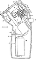
第1図は、本発明のシステムの第1実施例を示す図である。このシステムは、電気シェーバ1と、シェーバ1のチャンバ12に収容されるカートリッジ2とを有する。シェーバ1は、処理装置と、今回の場合、駆動可能なカッタ31を有するシェービングヘッド3と、結合ピン14を介してカッタ31を駆動する電気モータ11とを有する。カートリッジ2は、ダイアフラムポンプ23と、補助流体を保持する空間21を持つ貯留部25とを有する。補助流体は、望ましくはシェービングローションであり、そしてシェービングヘッド3と使用者の皮膚との間の摩擦を低減する潤滑成分を望ましくは有する。カートリッジ2は、補助流体を供給する出口チャネル22を有する。シェーバ1はさらに、カートリッジ2と結合するインタフェースを有する。シェーバ1のインタフェースは、カートリッジ2のインタフェースのフック24にかみ合うフック19を有する。フック19,24は、カートリッジ2の装着及び除去に幾らかの力を要するように形成される。シェーバ1のインタフェースは更に、補助流体の通過のための結合素子(今回の場合、出口開口32に出口チャネル22を結合するチューブ部分33)を有する。ダイアフラムポンプ23の作動のため、シェーバ1は、チャンバ12に延びるアクチュエータ13を有する。今回の場合、支点18を中心に回動可能なレバー17である機構により、アクチュエータ13をボタン15を動かして駆動できるように、アクチュエータ13がシェーバ1の外側でボタン15に結合される。ボタンが押下されると、ダイアフラムポンプ23は出口開口32を介して補助流体をわずかに供給する。
カートリッジ2は、ピンを介したレバー17の遮断に適応される遮断装置60と協働する機械的キー50を有する。このキー50は、遮断装置60のピンの位置合わせ用の突起を有する。突起の大きさは、遮断装置60のピンがポンプ23の動作を遮断するか否かを決定する。正しいキーが無い場合、レバー17は遮断され、そしてカートリッジの補助流体が出力開口32に押出される事態を回避する。
シェーバ1は更に、プリント基板41に装着されたスイッチ42を介してモータ11に結合可能なバッテリ44を有する。スイッチ42は、シェーバ1の外側のボタン43により作動可能である。この実施例は、シェービング用に補助流体が必要でなく、そして遮断装置60は、カートリッジが存在しなくともシェービングを許容する。
第2図は、アクチュエータ機能が遮断される本発明の第2実施例の一部を示す図である。この実施例において、ポンプ123の作動のためのスライド117は、遮断装置160によって遮断される。この遮断装置160は更に、弾性素子162によって遮断位置に保持される遮断素子161を有する。この遮断位置において、ポンプの作動が、遮断素子161がスライド117上の突出118用の止めを形成することにより遮断される。スライド117を機械的に遮断することの利点は、使用者が、ポンプ機能が遮断されていることを感じるということである。すなわち、使用者が、カートリッジが空であるもしくは詰まりが生じた、との結論を出す事態が回避される。
第3図は、アクチュエータ機能が遮断されない、本発明の第2実施例の一部を示す図である。遮断素子161の否遮断位置において、遮断素子161の開口163は、突出118が自由でかつ、ポンプ123がスライド117を介して動作できるような方法で、配置される。遮断素子161は、カートリッジ102の一部を形成するキーにより否遮断位置に移動される。カートリッジ102は、フランジ120及びフレキシブル壁121に封入された補助流体を保持する。フランジ120は補助流体の通過用に結合素子122を有する。キーは、ピン151を有し、フランジ上の該ピンの位置は、結合素子122がポンプ123の結合素子124に沿うときに遮断装置160の開口165の位置に対応する。キーは、遮断素子161の接触面164に対抗してかみ合うキー表面153を有する。ピン151は、遮断素子161が弾性素子162の圧力に対抗して否遮断位置に保持されるような長さLを有する。カートリッジ102上のキーは、ピン151と同様な長さを持つ第2ピン152を有する。この第2ピン152は、更に接触面164と協働するように適応されるキー面を有する。ピン151,152は、結合素子122に対して対称的に配置される。この対称性により、カートリッジ102は180度間が空けられた2つの異なる位置に装着できる。
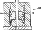
第4図は、本発明の第3実施例の一部を示す図である。この実施例において、キーは、結合素子222に対して対称的に配置された2つのピン251,252を有する。ピン251,252は、図示しないフレキシブルパッチに接続されたフランジ220の一部を形成する。遮断装置260は、2つのスプリング262,264により遮断位置に配置された2つの遮断素子261,262を有する。この遮断位置において、遮断素子261,262は、アクチュエータスライド273,274の一部を形成する2つの突出271,272を遮断する。この結果、アクチュエータスライド273,274に制御される機能が遮断される。スライド273,274は、両方のスライドが機能を作動させることを遮断されることがないような態様で結合されても良い。遮断素子271,272は、2つのピン251,252の何れかの存在が、遮断素子271,272を否遮断位置に設定するのに適するように、結合されて良い。
第5図は、フランジ220が第1位置で遮断素子260と協働しかつ、その機能が遮断されない本発明の第3実施例の一部を示す図である。遮断素子261,262の否遮断位置において、突出271,272が自由である。よって、アクチュエータスライド273,274は、図の平面に直交する方向に移動することができる。
第6図は、第2位置のフランジ220が遮断装置260と協働しかつ、その機能が遮断されない本発明の第3実施例の一部を示す図である。第3実施例において、遮断装置260は対称的で、そして各遮断素子は、2つの否遮断位置を有する。この結果、フランジ220は、180度離れた2つの異なる位置に装着可能で、一方、キーは非対称である。遮断装置260は同様に、ピン251又は252の長さに等しい長さの2つのピンを有するキーによりブロック解除される。この結果、異なるキー、異なる流体を持つ、そのすべてが遮断装置260をブロック解除するものである、異なるカートリッジの市場投入、そして、1つの突出の通過のための1つの開口を持つ遮断素子を有するためこれらのキーのうちの1つのみによってブロック解除されるような遮断素子を有する器具の市場投入が可能となる。
第7図は、光学キー及び光学検出器を有する実施例の一部を示す図である。この実施例において、カートリッジ302は、本発明の器具の適当なチャンバ312内にカートリッジが配置された場合に光学検出器361により読取られることができるバーコード350を有する。この器具は更に、検出回路を含む制御ユニット363を有する。この制御ユニットは、完全に又は部分的に、正しいバーコードの検出に基づいて、モータ11の駆動を実現する。このモータ11は、例えば、第1図に示されたカッタの駆動に向けられる。
第8図は、電気キー及び電気検出器を持つ実施例の一部を示す図である。この実施例において、カートリッジ402は、与えられた抵抗値を持つ抵抗453を介して相互接続された2つの接触面451,452を持つ。カートリッジが本発明の器具のチャンバ412にある場合、この抵抗値は、制御ユニット463の計測回路及び2つの電極461,462により測定可能である。与えられた抵抗値の検出に基づいて、モータ11のある速度は最早抑制されない。
第9図は、電磁キー及び電磁検出器を持つ実施例の一部を示す図である。この実施例において、カートリッジ502は、本発明による器具の適切なチャンバ512内にカートリッジ502が存在する場合、アンテナ561により読取可能な共振回路550を有する。この器具は更に、正しい共振周波数の検出に基づいて、モータ11の駆動を完全又は部分的に実現するデコーダ回路を持つ制御ユニット563を有する。
第10図は、磁気キー及び磁気ヘッドを持つ実施例の一部を示す図である。この実施例において、カートリッジ602は、カートリッジが本発明の器具の適切なチャンバ612内に配置される場合、磁気ヘッド661により読取られることができる磁気細片650を有する。この器具は更に、磁気細片上の正しいコードの検出に基づいて、モータ11の駆動を完全又は部分的に実現するデコーダ回路を持つ制御ユニット663を有する。
本発明は、上述の実施例に限定されないことに注意されたい。遮断機能は、与えられた形式又は与えられた処理速度による処理を伴うことも可能である。例えば、マッサージ装置の場合、補助流体は、マッサージオイルであってよく、カートリッジが正しく設けられる場合、より高速のマッサージ速度が許容される。すなわち、例えば、与えられた処理又は処理速度で使用者の肌への不適切な補助流体による不適切な作用を排除できる。なお、器具は、電気歯ブラシ、脱毛装置、又はスチーム装置としても利用可能で、補助流体は、例えば、歯磨き剤、ボディケアクリーム又はメンソール剤となる。TECHNICAL FIELD The present invention includes a cartridge having a space for storing an auxiliary fluid and an instrument, and the instrument is a processing device for processing a user's body with the aid of the auxiliary fluid, and the cartridge is used for the instrument. And a system for personal body care having an interface coupled to the . The present invention also relates to a device for body care, comprising a processing device for processing a user's body and an interface for coupling a cartridge having a space for storing auxiliary fluid to the device. . The present invention also relates to a cartridge that contains a space for storing auxiliary fluid for body care associated with a body-care treatment, and an instrument adapted to perform this treatment. The present invention relates to a cartridge having an interface for coupling the two . The present invention also relates to a pump and a flange for use in the cartridge according to the present invention.
BACKGROUND OF THE INVENTION A system, instrument and cartridge as described above are known from US patent application US-A-5402697. This known system has an electric shaver and a cartridge filled with a hair removal substance. This shaver has a shaving head, a drive unit, and a chamber for mounting the cartridge. As viewed from the shaving head, the chamber is disposed adjacent to the drive unit, and on the side of the shaver remote from the shaving head, there is a cover that allows the cartridge to be disposed in the chamber. On the shaving head side, the chamber communicates with a path that terminates at the outer surface of the shaving head. The cartridge has an activation button for supplying a hair removal substance. This cover has an opening that allows the user to operate the button in the closed position of the cover even when the cartridge is disposed in the shaver. A disadvantage of the known systems, a shaver, in combination with the shaver would be used in conjunction with a cartridge containing the fluid that has not been tested, in that.
DISCLOSURE OF THE INVENTION It is an object of the present invention to provide a system, device and cartridge of the type defined in the opening paragraph that can avoid the undesired consequences of using an inappropriate auxiliary fluid.
For this purpose, the system of the invention
The appliance includes a blocking device adapted to block at least one function of the appliance;
The cartridge has a key that cooperates with the shut-off device;
The blocking device is adapted to unblock the function when the cartridge is installed .
The device of the present invention is suitable for use in the system of the present invention, and thus
The appliance includes a blocking device adapted to block at least one function of the appliance;
The blocking device is adapted to unblock the function when a cartridge with a key is coupled to the instrument .
The cartridge of the present invention is suitable for use in the system according to the present invention, so that the cartridge is
When the cartridge is coupled to the instrument, it has a key for unblocking the function of the instrument .
The present invention is the use of auxiliary fluids which cooperates with instruments for performing cleaning process of the body to the user's body, an auxiliary fluid is forced to special requirements based on the recognition of the fact that. It is not sufficient that such an auxiliary fluid itself is suitable for application to the body. It seems that the effects on the body can change under the influence of treatment. When adding the auxiliary fluid is Rubeki can be easily removed from the instrument and the auxiliary fluid to the instrument should not act. The measure according to the invention suppresses functions that can produce undesirable results if there are cartridges that do not have the correct keys. Prevention of undesirable results, the cartridge with the correct key is achieved by the fact that is exclusively filled only with fluid tested in conjunction with the instrument.
An embodiment of the device according to the invention is characterized by what is defined in the characterizing part of claim 3. That is, inappropriate use of auxiliary fluid is eliminated .
An embodiment of the device according to the invention is characterized by what is defined in the characterizing part of claim 4. This embodiment is processing dry, that is, the care without using an auxiliary fluid, wet, that is, of particular interest when it is capable of both cleaning using an auxiliary fluid. In such cases, this measure eliminates the use of inappropriate auxiliary fluids, for example, by blocking the pump while allowing the instrument to be used in “dry” mode.
An embodiment of the device according to the invention is characterized by what is defined in the characterizing part of claim 5. This embodiment is particularly suitable for interrupting mechanical functions, such as valve actuation or pump actuation . In addition, this embodiment has the advantage that it is relatively insensitive to dirt. Such contamination is not likely to be caused by, for example, an auxiliary fluid . Furthermore, this embodiment does not depend on the power supply, thus eliminating the shut-down device shut down due to insufficient power supply voltage, for example.
An embodiment of the device according to the invention is characterized by what is defined in the characterizing part of claim 6. With this measure, both the size and position of the pin-shaped protrusions form variables that define different keys. As a result, systems for body care can have a cartridge with different fluids and different keys from each other. At this time, it may be desirable to block different functions of the instrument of the system depending on the key. Key with two different variables, allows the operation of the old device in combination with the new fluids and blocking new appliances against the old fluid, or blocking the old appliances for the new fluid, the old fluid On the other hand, new instruments and fluids can be marketed with the possibility of allowing new instruments to operate.
An embodiment of the device according to the invention is characterized by what is specified in the characterizing part of claim 7. Such symmetry, because the cartridge can be attached to the instrument in two positions, to simplify the mounting of the cartridge into the instrument.
An embodiment of the device according to the invention is characterized by what is defined in the characterizing part of claim 8. This key has, for example, a pattern of higher and lower reflective surfaces that are read when the cartridge is mounted on the instrument. This measure forces the state does not occur is realized between the cartridge and the instrument in the presence of a key.
An embodiment of the device according to the invention is characterized by what is specified in the characterizing part of claim 9. This measure, detection key is less susceptible to soiling by the auxiliary fluid. The key can take the form of a magnetic strip, for example, and a magnetic detector detects a magnetic pattern provided on the magnetic strip. In another example, the key may include an inductive element and the magnetic detector may include an antenna for generating and detecting an alternating magnetic field.
An embodiment of the device according to the invention is characterized by what is specified in the characterizing part of claim 10. With this measure , the electrically controlled function of the instrument can be cut off in a simple manner. In this case the key has a pattern of electrode surface which is not the connected or connected to each other, and the electrical detector having a pattern of two or more electrodes. Electrode surface, the electrical resistance given, be connected via a capacitor or a coil may, or may form a digital pattern of surfaces that are not or connected are electrically connected to each other.
An embodiment of the cartridge according to the invention is characterized by what is specified in the characterizing part of
An embodiment of the cartridge according to the invention is characterized by what is specified in the characterizing part of
An embodiment of the cartridge according to the invention is characterized by what is defined in the characterizing part of
An embodiment of the cartridge according to the invention is characterized by what is specified in the characterizing part of
The invention will be described in more detail below with reference to the drawings.
[Brief description of the drawings]
FIG. 1 is a sectional view showing a first embodiment of the system according to the present invention.
FIG. 2 is a cross-sectional view showing a part of a second embodiment of the present invention in which the actuator function is interrupted.
FIG. 3 is a sectional view showing a part of the second embodiment of the present invention in which the actuator function is not interrupted.
FIG. 4 is a sectional view showing a part of the third embodiment of the present invention.
FIG. 5 is a sectional view showing a part of a third embodiment of the present invention in which the flange in the first position cooperates with the shut-off device .
FIG. 6 is a sectional view showing a part of a third embodiment of the present invention in which the flange in the second position cooperates with the shut-off device .
7 is a diagram showing a part of the embodiment having an optical key and an optical detector.
8 is a diagram showing a part of the embodiment having an electrical key and an electrical detector.
9 is a diagram showing a part of the embodiment having an electromagnetic key and an electromagnetic detector.
FIG. 10 is a diagram showing a part of the embodiment having a magnetic key and a magnetic head.
BEST MODE FOR CARRYING OUT THE INVENTION FIG. 1 is a diagram showing a first embodiment of the system of the present invention. This system has the
The
The
FIG. 2 is a diagram showing a part of the second embodiment of the present invention in which the actuator function is interrupted. In this embodiment, the
FIG. 3 shows a part of the second embodiment of the present invention in which the actuator function is not interrupted. In the non-blocking position of the blocking
FIG. 4 shows a part of the third embodiment of the present invention. In this embodiment, the key has two
FIG. 5 shows a part of a third embodiment of the invention in which the
FIG. 6 is a view showing a part of the third embodiment of the present invention in which the
FIG. 7 is a diagram showing a part of an embodiment having an optical key and an optical detector. In this embodiment, the
FIG. 8 is a diagram showing a part of an embodiment having an electric key and an electric detector. In this embodiment, the
FIG. 9 is a diagram showing a part of an embodiment having an electromagnetic key and an electromagnetic detector. In this embodiment, the
FIG. 10 is a diagram showing a part of an embodiment having a magnetic key and a magnetic head. In this embodiment, the
It should be noted that the present invention is not limited to the embodiments described above. The shut-off function may involve processing according to a given type or a given processing speed. For example, if the massage device, the auxiliary fluid may be a massaging oil, when the cartridge is provided correctly, faster massage speed is acceptable. That is, for example, an inappropriate action due to an inappropriate auxiliary fluid on the user's skin at a given processing or processing speed can be eliminated. Incidentally, the instrument electrical toothbrushes, epilation device or also available as a steam device, the auxiliary fluid, for example, a dentifrice, body care cream or menthol agents.
Claims (19)
前記カートリッジを当該器具に結合するインタフェースと、
を有する、体の手入れのためのシステムにおいて、
前記器具が、当該器具の少なくとも一つの機能を遮断する遮断装置を含み、
前記カートリッジが、前記遮断装置と協働するキーを有し、
前記カートリッジが前記器具に装着された場合、前記遮断装置は、前記キーにより前記機能の遮断を解除することを特徴とする体の手入れのためのシステム。A cartridge having a space for storing an auxiliary fluid, and a device, the device performing a process on a user's body with the aid of the auxiliary fluid;
An interface for coupling the cartridge to the instrument;
In a system for body care having
The instrument includes a blocking device that blocks at least one function of the instrument;
The cartridge has a key that cooperates with the shut-off device;
When the cartridge is attached to the device, the blocking device releases the blocking of the function by the key, and is a system for body care.
使用者の体に処理を施す処理装置と、
補助流体を格納する空間を持つカートリッジを当該器具に結合するインタフェースと、
を有する器具において、
前記器具が、当該器具の少なくとも一つの機能を遮断する遮断装置を含み、
前記遮断装置と協動するキーを持つカートリッジが前記器具に結合される場合、前記遮断装置は、前記キーにより前記機能の遮断を解除することを特徴とする体の手入れのための器具。An instrument for caring for the body,
A processing device for processing the user's body;
An interface for coupling a cartridge having a space for storing auxiliary fluid to the device;
In a device having
The instrument includes a blocking device that blocks at least one function of the instrument;
An apparatus for caring for a body , wherein when a cartridge having a key that cooperates with the blocking device is coupled to the device, the blocking device releases the blocking of the function by the key .
前記機能が前記補助流体を利用することを含むことを特徴とする体の手入れのための器具。The instrument of claim 2,
A body care instrument, wherein the function includes utilizing the auxiliary fluid.
前記処理装置は、補助流体を必要としない処理の実施をすることができ、
前記遮断装置は、前記カートリッジが装着されていない場合、前記補助流体を必要としない処理を許可するように構成されていることを特徴とする体の手入れのための器具。The instrument according to claim 2 or 3,
The processing device can perform processing that does not require an auxiliary fluid,
The apparatus for caring for a body characterized in that the blocking device is configured to permit a process that does not require the auxiliary fluid when the cartridge is not mounted .
前記遮断装置が、遮断位置において前記機能を遮断しかつ、否遮断位置において当該機能を許容する少なくとも一つの遮断素子を有し、
前記遮断装置が、キー表面により前記遮断素子を位置決めする少なくとも一つの接触面を有することを特徴とする体の手入れのための器具。The instrument of claim 2,
The blocking device has at least one blocking element that blocks the function at a blocking position and allows the function at a blocking position;
A device for caring for the body, characterized in that the blocking device has at least one contact surface for positioning the blocking element by means of a key surface.
前記接触面が前記器具の壁の開口を介してのみアクセス可能であることを特徴とする体の手入れのための器具。The instrument of claim 5,
Device for body care, characterized in that the contact surface is accessible only through an opening in the wall of the device.
当該器具が、前記補助流体を通過させる結合素子を有し、
前記遮断装置が前記結合素子に対して対称的に構築されていることを特徴とする体の手入れのための器具。The instrument of claim 6,
The instrument has a coupling element for passing the auxiliary fluid;
An instrument for body care, characterized in that the blocking device is constructed symmetrically with respect to the coupling element.
前記遮断装置が前記器具に結合されるカートリッジ上の光学キーを検出する光学検出器を有し、
前記遮断装置が前記検出器に結合された制御ユニットを持つことを特徴とする体の手入れのための器具。The instrument of claim 2,
The shut-off device comprises an optical detector for detecting an optical key on a cartridge coupled to the instrument;
An instrument for body care, characterized in that the shut-off device has a control unit coupled to the detector.
前記遮断装置が前記器具に結合されたカートリッジ上の磁気キー又は電磁キーを検出する磁気検出器又は電磁検出器を有し、
前記遮断装置が前記検出器に結合された制御ユニットを持つことを特徴とする体の手入れのための器具。The instrument of claim 2,
The shut-off device comprises a magnetic detector or electromagnetic detector for detecting a magnetic key or electromagnetic key on a cartridge coupled to the instrument;
An instrument for body care, characterized in that the shut-off device has a control unit coupled to the detector.
前記遮断装置が前記器具に結合されたカートリッジの接触面との係合のための少なくとも2つの電極を有し、
前記遮断装置が、前記電極に結合された制御ユニットを有することを特徴とする体の手入れのための器具。The instrument of claim 2,
The shut-off device has at least two electrodes for engagement with a contact surface of a cartridge coupled to the instrument;
A body care instrument, wherein the shut-off device comprises a control unit coupled to the electrode.
体の手入れ処理と関連した体の手入れのための補助流体を格納する空間と、
この処理を実施する器具に当該カートリッジを結合するインタフェースと、
を有するカートリッジにおいて、
当該カートリッジは、当該カートリッジが前記器具に結合される場合、前記器具の機能をブロック解除するキーを有することを特徴とするカートリッジ。A cartridge,
A space for storing auxiliary fluid for body care associated with the body care process;
An interface for coupling the cartridge to an instrument for performing the process ;
In a cartridge having
The cartridge has a key for unblocking the function of the instrument when the cartridge is coupled to the instrument.
前記キーが、少なくとも一つのピン形状突出を有し、当該ピン形状突出の位置及び長さが前記キーを規定することを特徴とするカートリッジ。The cartridge according to claim 11, wherein
The cartridge, wherein the key has at least one pin-shaped protrusion, and the position and length of the pin-shaped protrusion define the key.
前記キーが少なくとも2つのピン形状突出を有することを特徴とするカートリッジ。The cartridge according to claim 12, wherein
A cartridge wherein the key has at least two pin-shaped protrusions.
当該カートリッジが、前記補助流体を通過させる結合素子を有し、
前記ピン形状突出が前記結合素子に対して対称的に配置されることを特徴とするカートリッジ。The cartridge according to claim 13,
The cartridge has a coupling element for passing the auxiliary fluid;
The cartridge, wherein the pin-shaped protrusions are arranged symmetrically with respect to the coupling element.
前記キーが光学キーを有することを特徴とするカートリッジ。The cartridge according to claim 11, wherein
A cartridge wherein the key has an optical key.
前記キーが磁気キー又は電磁キーを有することを特徴とするカートリッジ。The cartridge according to claim 11, wherein
A cartridge wherein the key includes a magnetic key or an electromagnetic key.
前記キーは、間に電気素子が配置された少なくとも2つの接触面を有することを特徴とするカートリッジ。The cartridge according to claim 11, wherein
The cartridge has at least two contact surfaces with an electric element disposed between the keys.
当該カートリッジが貯留部及びポンプを有し、
前記キーが前記ポンプの一部を形成することを特徴とするカートリッジ。The cartridge according to claim 11, wherein
The cartridge has a reservoir and a pump;
A cartridge wherein the key forms part of the pump.
当該カートリッジが貯留部及びポンプを有し、
前記ポンプが前記貯留部から取り外し自在であることを特徴とするカートリッジ。The cartridge according to claim 11, wherein
The cartridge has a reservoir and a pump;
The cartridge, wherein the pump is removable from the storage part.
Applications Claiming Priority (3)
| Application Number | Priority Date | Filing Date | Title |
|---|---|---|---|
| EP97201704 | 1997-06-05 | ||
| EP97201704.0 | 1997-06-05 | ||
| PCT/IB1998/000545 WO1998055274A1 (en) | 1997-06-05 | 1998-04-09 | System, appliance and cartridge for personal body care |
Publications (3)
| Publication Number | Publication Date |
|---|---|
| JP2000516124A JP2000516124A (en) | 2000-12-05 |
| JP2000516124A5 JP2000516124A5 (en) | 2005-11-24 |
| JP4341988B2 true JP4341988B2 (en) | 2009-10-14 |
Family
ID=8228409
Family Applications (1)
| Application Number | Title | Priority Date | Filing Date |
|---|---|---|---|
| JP52939998A Expired - Fee Related JP4341988B2 (en) | 1997-06-05 | 1998-04-09 | System, instrument and cartridge for caring for the body |
Country Status (7)
| Country | Link |
|---|---|
| US (1) | US6131288A (en) |
| EP (1) | EP0930960B1 (en) |
| JP (1) | JP4341988B2 (en) |
| AT (1) | ATE246576T1 (en) |
| DE (1) | DE69816960T2 (en) |
| ES (1) | ES2202822T3 (en) |
| WO (1) | WO1998055274A1 (en) |
Families Citing this family (41)
| Publication number | Priority date | Publication date | Assignee | Title |
|---|---|---|---|---|
| DE69921617T2 (en) * | 1998-12-29 | 2005-10-20 | Koninklijke Philips Electronics N.V. | shaving |
| DE19907224C2 (en) * | 1999-02-19 | 2001-02-22 | Braun Gmbh | Liquid container |
| DE19907025A1 (en) | 1999-02-19 | 2000-08-31 | Braun Gmbh | Hair removal device |
| US6530150B1 (en) * | 1999-05-17 | 2003-03-11 | Benjamin J. Barish | Attachments for electrical shaver and auxiliary cleaning device useful for electrical shaver |
| EP1261895B1 (en) * | 1999-12-10 | 2005-11-23 | Sensopad Limited | Man-machine interface having relative position sensor |
| US7086111B2 (en) | 2001-03-16 | 2006-08-08 | Braun Gmbh | Electric dental cleaning device |
| DE10159395B4 (en) | 2001-12-04 | 2010-11-11 | Braun Gmbh | Device for cleaning teeth |
| JP4443116B2 (en) | 2001-03-14 | 2010-03-31 | ブラウン ゲーエムベーハー | Teeth cleaning method and apparatus |
| DE60324894D1 (en) * | 2002-02-13 | 2009-01-08 | Matsushita Electric Works Ltd | HAIR REMOVAL DEVICE WITH LOTION TREATMENT DEVICE |
| US7438202B2 (en) * | 2002-12-03 | 2008-10-21 | Koninklijke Philips Electronics N.V. | Hair removing apparatus |
| US20040107578A1 (en) * | 2002-12-04 | 2004-06-10 | Steele James M. | Blade sharpening for electric shavers |
| KR20050091007A (en) * | 2002-12-19 | 2005-09-14 | 코닌클리케 필립스 일렉트로닉스 엔.브이. | Discrete-amount fluid-dispensing system for a personal care device |
| WO2005000541A1 (en) | 2003-06-30 | 2005-01-06 | Koninklijke Philips Electronics N.V. | Appliance, cartridge and system for personal care with auxiliary fluid |
| US7137203B2 (en) * | 2003-12-30 | 2006-11-21 | Eveready Battery Company, Inc. | Shaving apparatus |
| DE102004015759A1 (en) * | 2004-03-31 | 2005-10-20 | Braun Gmbh | Electric hair removal device for partially or completely removing hair from the skin |
| US8615886B1 (en) * | 2004-05-06 | 2013-12-31 | Winthrop D. Childers | Shaving system with energy imparting device |
| EP1887909B1 (en) | 2005-05-03 | 2018-04-18 | Colgate-Palmolive Company | Toothbrush assembly |
| EP1903902B1 (en) | 2005-06-16 | 2009-08-12 | Koninklijke Philips Electronics N.V. | A cartridge for an appliance for personal care and an appliance comprising such a cartridge |
| US7367126B2 (en) * | 2005-09-06 | 2008-05-06 | The Gillette Company | Powered wet-shaving razor |
| DE102005063196A1 (en) | 2005-12-30 | 2007-07-05 | Braun Gmbh | Application material container for electrical tooth brush, has data carrier readable by tooth brush, and comprising data memory writeable by tooth brush, where container can be filled with tooth paste or other application material |
| US7788810B2 (en) * | 2006-07-24 | 2010-09-07 | Eveready Battery Company, Inc. | Shaving system having an umbilical |
| WO2009131670A2 (en) * | 2008-04-21 | 2009-10-29 | Poly-D, Llc | Replaceable cartridge dispenser assembly |
| CA2715247A1 (en) | 2008-05-07 | 2009-11-12 | Colgate-Palmolive Company | Interactive toothbrush and removeable audio output module |
| EP2236054A1 (en) * | 2009-04-04 | 2010-10-06 | Braun GmbH | Body grooming device |
| CN102452091B (en) | 2010-10-28 | 2015-08-12 | 吉列公司 | For the application device with deflector of hair removal device |
| CN102452096A (en) | 2010-10-28 | 2012-05-16 | 吉列公司 | Handle part of hair removing device used for distributing liquid |
| CN102452085B (en) | 2010-10-28 | 2016-01-27 | 吉列公司 | For the pump of the hair removal device of dispense liquid |
| CN102452095B (en) | 2010-10-28 | 2014-10-29 | 吉列公司 | Applicator of hair removing device for distributing liquid |
| CN102452088B (en) | 2010-10-28 | 2015-07-01 | 吉列公司 | Hair removing device with blade holder holding covering part |
| CN102452092B (en) | 2010-10-28 | 2015-04-01 | 吉列公司 | Hair removing device for dispensing liquid |
| CN102452094A (en) | 2010-10-28 | 2012-05-16 | 吉列公司 | Hair removing kit for distributing liquid |
| US8808060B2 (en) | 2011-04-12 | 2014-08-19 | Clipp-Aid Llc | Systems and methods for sharpening cutting blades |
| US20130020351A1 (en) * | 2011-07-21 | 2013-01-24 | Gojo Industries, Inc. | Dispenser with optical keying system |
| DK2550937T3 (en) | 2011-07-25 | 2014-05-19 | Braun Gmbh | MAGNETIC CONNECTION BETWEEN A TOOTH BRUSH AND A BRUSH HEAD |
| EP2550938B1 (en) | 2011-07-25 | 2015-01-14 | Braun GmbH | Oral hygiene device |
| WO2013014632A1 (en) | 2011-07-25 | 2013-01-31 | Braun Gmbh | Linear electro-polymer motors and devices having the same |
| US9156175B2 (en) * | 2011-12-09 | 2015-10-13 | The Gillette Company | Fluid applicator for a personal-care appliance |
| PT3062972T (en) * | 2014-02-07 | 2017-06-14 | C Talavera Victor | Hair trimming device |
| BR112018013826B1 (en) * | 2016-01-12 | 2021-12-21 | Koninklijke Philips N.V. | HOUSEHOLD APPLIANCE AND MODULE |
| EP3300864B1 (en) * | 2016-09-28 | 2021-12-15 | Braun GmbH | Electric shaver |
| US11731297B2 (en) * | 2021-06-17 | 2023-08-22 | Sincerely Ltd. B.V. | Personal care devices and components |
Family Cites Families (7)
| Publication number | Priority date | Publication date | Assignee | Title |
|---|---|---|---|---|
| US2686361A (en) * | 1953-04-07 | 1954-08-17 | Resnick Hyman | Reservoir safety razor |
| US2786270A (en) * | 1954-08-31 | 1957-03-26 | Orlando Carl | Self-lubricating shaver |
| US3103299A (en) * | 1959-10-01 | 1963-09-10 | August R Werft | Method of shaving |
| US3726009A (en) * | 1971-04-12 | 1973-04-10 | S Hackmyer | Self-lathering shaver |
| US5016351A (en) * | 1990-03-15 | 1991-05-21 | Drahus Denis P | Disposable safety razor system |
| US5092041A (en) * | 1991-06-10 | 1992-03-03 | Grigory Podolsky | Universal shaving device |
| US5402697A (en) * | 1993-11-18 | 1995-04-04 | Brooks; Shirley E. | Depilatory applicating razor |
-
1998
- 1998-04-09 AT AT98910931T patent/ATE246576T1/en not_active IP Right Cessation
- 1998-04-09 EP EP98910931A patent/EP0930960B1/en not_active Expired - Lifetime
- 1998-04-09 WO PCT/IB1998/000545 patent/WO1998055274A1/en active IP Right Grant
- 1998-04-09 DE DE69816960T patent/DE69816960T2/en not_active Expired - Lifetime
- 1998-04-09 ES ES98910931T patent/ES2202822T3/en not_active Expired - Lifetime
- 1998-04-09 JP JP52939998A patent/JP4341988B2/en not_active Expired - Fee Related
- 1998-06-05 US US09/092,312 patent/US6131288A/en not_active Ceased
Also Published As
| Publication number | Publication date |
|---|---|
| EP0930960A1 (en) | 1999-07-28 |
| WO1998055274A1 (en) | 1998-12-10 |
| JP2000516124A (en) | 2000-12-05 |
| EP0930960B1 (en) | 2003-08-06 |
| ES2202822T3 (en) | 2004-04-01 |
| US6131288A (en) | 2000-10-17 |
| DE69816960D1 (en) | 2003-09-11 |
| DE69816960T2 (en) | 2004-06-17 |
| ATE246576T1 (en) | 2003-08-15 |
Similar Documents
| Publication | Publication Date | Title |
|---|---|---|
| JP4341988B2 (en) | System, instrument and cartridge for caring for the body | |
| USRE38634E1 (en) | System appliance and cartridge for personal body care | |
| JP4240539B2 (en) | Personal body care system and equipment for it | |
| US6126669A (en) | Depilation system | |
| US5794342A (en) | Oscillating blade razor | |
| US7788810B2 (en) | Shaving system having an umbilical | |
| TWI227689B (en) | Hair removing device with a lotion applicator | |
| EP1363760B1 (en) | Refill and storage holder for personal care appliance | |
| KR100586788B1 (en) | Hair removing device with a lotion applicator | |
| US3653377A (en) | Portable power-operated douching appliance | |
| EP1737626B1 (en) | Personal care appliance for treatment of a body part with means for dispensing an additive onto said body part to be treated | |
| KR100978178B1 (en) | Razors | |
| US4549352A (en) | Washable electric shaver | |
| JPH0347856B2 (en) | ||
| JP2009506822A (en) | Razor | |
| US8316545B2 (en) | Hair removing apparatus | |
| US20220355497A1 (en) | Electric grooming device | |
| KR100430855B1 (en) | Washing apparatus of beauty culture tool with ultrasonic generator | |
| RU2255707C2 (en) | Dents cleaning device | |
| JP2004113397A (en) | Body hair treatment device | |
| JPS5948112B2 (en) | Electric razor beard waste disposal device |
Legal Events
| Date | Code | Title | Description |
|---|---|---|---|
| A524 | Written submission of copy of amendment under article 19 pct |
Free format text: JAPANESE INTERMEDIATE CODE: A524 Effective date: 20050408 |
|
| A621 | Written request for application examination |
Free format text: JAPANESE INTERMEDIATE CODE: A621 Effective date: 20050408 |
|
| A131 | Notification of reasons for refusal |
Free format text: JAPANESE INTERMEDIATE CODE: A131 Effective date: 20080408 |
|
| A601 | Written request for extension of time |
Free format text: JAPANESE INTERMEDIATE CODE: A601 Effective date: 20080708 |
|
| A602 | Written permission of extension of time |
Free format text: JAPANESE INTERMEDIATE CODE: A602 Effective date: 20080818 |
|
| A521 | Request for written amendment filed |
Free format text: JAPANESE INTERMEDIATE CODE: A523 Effective date: 20081007 |
|
| TRDD | Decision of grant or rejection written | ||
| A01 | Written decision to grant a patent or to grant a registration (utility model) |
Free format text: JAPANESE INTERMEDIATE CODE: A01 Effective date: 20090609 |
|
| A01 | Written decision to grant a patent or to grant a registration (utility model) |
Free format text: JAPANESE INTERMEDIATE CODE: A01 |
|
| A61 | First payment of annual fees (during grant procedure) |
Free format text: JAPANESE INTERMEDIATE CODE: A61 Effective date: 20090707 |
|
| FPAY | Renewal fee payment (event date is renewal date of database) |
Free format text: PAYMENT UNTIL: 20120717 Year of fee payment: 3 |
|
| R150 | Certificate of patent or registration of utility model |
Free format text: JAPANESE INTERMEDIATE CODE: R150 |
|
| FPAY | Renewal fee payment (event date is renewal date of database) |
Free format text: PAYMENT UNTIL: 20120717 Year of fee payment: 3 |
|
| FPAY | Renewal fee payment (event date is renewal date of database) |
Free format text: PAYMENT UNTIL: 20130717 Year of fee payment: 4 |
|
| R250 | Receipt of annual fees |
Free format text: JAPANESE INTERMEDIATE CODE: R250 |
|
| R250 | Receipt of annual fees |
Free format text: JAPANESE INTERMEDIATE CODE: R250 |
|
| R250 | Receipt of annual fees |
Free format text: JAPANESE INTERMEDIATE CODE: R250 |
|
| R250 | Receipt of annual fees |
Free format text: JAPANESE INTERMEDIATE CODE: R250 |
|
| LAPS | Cancellation because of no payment of annual fees |