JP4339932B2 - Joint forming device - Google Patents
Joint forming device Download PDFInfo
- Publication number
- JP4339932B2 JP4339932B2 JP53935598A JP53935598A JP4339932B2 JP 4339932 B2 JP4339932 B2 JP 4339932B2 JP 53935598 A JP53935598 A JP 53935598A JP 53935598 A JP53935598 A JP 53935598A JP 4339932 B2 JP4339932 B2 JP 4339932B2
- Authority
- JP
- Japan
- Prior art keywords
- sleeve
- fastening element
- rotation
- pin
- cam
- Prior art date
- Legal status (The legal status is an assumption and is not a legal conclusion. Google has not performed a legal analysis and makes no representation as to the accuracy of the status listed.)
- Expired - Fee Related
Links
- 230000002093 peripheral effect Effects 0.000 claims description 7
- 230000033001 locomotion Effects 0.000 description 31
- 230000013011 mating Effects 0.000 description 16
- 238000000034 method Methods 0.000 description 8
- 238000000465 moulding Methods 0.000 description 5
- 230000006835 compression Effects 0.000 description 4
- 238000007906 compression Methods 0.000 description 4
- 238000004512 die casting Methods 0.000 description 4
- 229910052751 metal Inorganic materials 0.000 description 4
- 239000002184 metal Substances 0.000 description 4
- 239000000463 material Substances 0.000 description 2
- HCHKCACWOHOZIP-UHFFFAOYSA-N Zinc Chemical compound [Zn] HCHKCACWOHOZIP-UHFFFAOYSA-N 0.000 description 1
- 239000000956 alloy Substances 0.000 description 1
- 229910045601 alloy Inorganic materials 0.000 description 1
- 230000006378 damage Effects 0.000 description 1
- 230000007423 decrease Effects 0.000 description 1
- 230000026058 directional locomotion Effects 0.000 description 1
- 230000000694 effects Effects 0.000 description 1
- 238000005516 engineering process Methods 0.000 description 1
- 150000002739 metals Chemical class 0.000 description 1
- 229910052725 zinc Inorganic materials 0.000 description 1
- 239000011701 zinc Substances 0.000 description 1
Images


Classifications
-
- F—MECHANICAL ENGINEERING; LIGHTING; HEATING; WEAPONS; BLASTING
- F16—ENGINEERING ELEMENTS AND UNITS; GENERAL MEASURES FOR PRODUCING AND MAINTAINING EFFECTIVE FUNCTIONING OF MACHINES OR INSTALLATIONS; THERMAL INSULATION IN GENERAL
- F16B—DEVICES FOR FASTENING OR SECURING CONSTRUCTIONAL ELEMENTS OR MACHINE PARTS TOGETHER, e.g. NAILS, BOLTS, CIRCLIPS, CLAMPS, CLIPS OR WEDGES; JOINTS OR JOINTING
- F16B12/00—Jointing of furniture or the like, e.g. hidden from exterior
- F16B12/10—Jointing of furniture or the like, e.g. hidden from exterior using pegs, bolts, tenons, clamps, clips, or the like
- F16B12/12—Jointing of furniture or the like, e.g. hidden from exterior using pegs, bolts, tenons, clamps, clips, or the like for non-metal furniture parts, e.g. made of wood, of plastics
- F16B12/20—Jointing of furniture or the like, e.g. hidden from exterior using pegs, bolts, tenons, clamps, clips, or the like for non-metal furniture parts, e.g. made of wood, of plastics using clamps, clips, wedges, sliding bolts, or the like
- F16B12/2009—Jointing of furniture or the like, e.g. hidden from exterior using pegs, bolts, tenons, clamps, clips, or the like for non-metal furniture parts, e.g. made of wood, of plastics using clamps, clips, wedges, sliding bolts, or the like actuated by rotary motion
- F16B12/2027—Jointing of furniture or the like, e.g. hidden from exterior using pegs, bolts, tenons, clamps, clips, or the like for non-metal furniture parts, e.g. made of wood, of plastics using clamps, clips, wedges, sliding bolts, or the like actuated by rotary motion with rotating excenters or wedges
- F16B12/2036—Jointing of furniture or the like, e.g. hidden from exterior using pegs, bolts, tenons, clamps, clips, or the like for non-metal furniture parts, e.g. made of wood, of plastics using clamps, clips, wedges, sliding bolts, or the like actuated by rotary motion with rotating excenters or wedges with rotating excenters or wedges acting on a head of a pin or screw
-
- A—HUMAN NECESSITIES
- A47—FURNITURE; DOMESTIC ARTICLES OR APPLIANCES; COFFEE MILLS; SPICE MILLS; SUCTION CLEANERS IN GENERAL
- A47B—TABLES; DESKS; OFFICE FURNITURE; CABINETS; DRAWERS; GENERAL DETAILS OF FURNITURE
- A47B2230/00—Furniture jointing; Furniture with such jointing
- A47B2230/0029—Dowels
- A47B2230/0033—Expansible dowels or dowel-pins
-
- Y—GENERAL TAGGING OF NEW TECHNOLOGICAL DEVELOPMENTS; GENERAL TAGGING OF CROSS-SECTIONAL TECHNOLOGIES SPANNING OVER SEVERAL SECTIONS OF THE IPC; TECHNICAL SUBJECTS COVERED BY FORMER USPC CROSS-REFERENCE ART COLLECTIONS [XRACs] AND DIGESTS
- Y10—TECHNICAL SUBJECTS COVERED BY FORMER USPC
- Y10T—TECHNICAL SUBJECTS COVERED BY FORMER US CLASSIFICATION
- Y10T403/00—Joints and connections
- Y10T403/46—Rod end to transverse side of member
- Y10T403/4602—Corner joint
-
- Y—GENERAL TAGGING OF NEW TECHNOLOGICAL DEVELOPMENTS; GENERAL TAGGING OF CROSS-SECTIONAL TECHNOLOGIES SPANNING OVER SEVERAL SECTIONS OF THE IPC; TECHNICAL SUBJECTS COVERED BY FORMER USPC CROSS-REFERENCE ART COLLECTIONS [XRACs] AND DIGESTS
- Y10—TECHNICAL SUBJECTS COVERED BY FORMER USPC
- Y10T—TECHNICAL SUBJECTS COVERED BY FORMER US CLASSIFICATION
- Y10T403/00—Joints and connections
- Y10T403/76—Joints and connections having a cam, wedge, or tapered portion
Abstract
Description
本発明は接合部形成装置、特に組立式家具の2つの部材間で接合部を形成する接合部形成装置に関するが、それに限定されるものではない。
出願人の米国特許第5567081号は、2つの部材間に接合部を形成する接合部形成装置を開示している。本出願の図面類の図1を参照すると、既知の接合部形成装置は、細長い締結要素10および回転可能な締付け要素12を備える。締結要素10は、少なくとも頭部分16が接合部材から突き出すよう、接合部材の第1(14)に固定することができる。締付け要素12は、接合部材の第2(20)にある凹部18に、回転可能な状態で装着され、締結要素の頭部分16と嵌合可能な2つの弓形カム表面22を有する。
接合部形成装置は、さらに、締結要素10のスリーブ24を備える。スリーブ24の一方端は、第1接合部材14の凹部26に適合することができる。締結要素10は、締結要素をスリーブに対して軸方向に移動させると、スリーブが拡張し、凹部26の壁30と強制的に嵌合するよう配置された複数テーパ付き端部分28を有する。
使用時には、スリーブ24を締結要素10に取り付けて、第2接合部材20の内腔32に挿入する。内腔32は凹部18に対して直角に延在し、これと交差する。スリーブ24を内腔32に正しく挿入した状態で、カム表面22が嵌合可能になるよう、締結要素の頭部分16を締付け要素の中空の中心領域で受ける。これが基本的に、図1aに示す締結要素、スリーブおよび締付け要素の位置である。
2つの部材14、20間に接合部を形成するために、内腔32で受けていないスリーブ24の端部を第1接合部材14の凹部26に挿入する。次に、締付け要素を、締結要素の縦軸に対して垂直であるその回転軸を中心に回転させる。締付け要素をこのように回転させるにつれ、カム表面22の動作が、締結要素を第1接合部材14から軸方向に離れるよう引っ張る。スリーブは、第2接合部材の端面36に突き当てられたスリーブ・カラー34によって、締結要素とともに動くことができない。締結要素とスリーブとの相対的な動きにより、複数テーパ付き端部分28はスリーブの内側に引っ張られるので、拡張し、凹部26の壁30と強制的に嵌合する。締結要素をさらに回転させると、接合部材同士がぴったり引き寄せられ、したがって接合部材が圧縮状態になり、締結要素が引張りの状態になる。
締付け要素を第2接合部材の端面36に対して正しく配置しないと、このような接合部形成装置には問題が生じることがある。締付け要素をその縁に近づけすぎると、接合部を締め付けることが不可能なことが判明する。というのは、各カム表面の長さの小さい部分しか、締付け要素の回転時に有効でないからである。その結果、締結要素には非常に小さい引張り力しかかからず、接合部の圧縮が小さくなり、したがって接合が弱くなる。締付け要素が第2接合部材の縁から遠すぎると、不当な量の力をかけない限り、締付け方向に締付け要素を少量しか回転することができない。
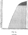
既知のカム要素のカム表面は、通常、2段階の締付け作用を提供するようになっている縦方向の輪郭を有する。図1bは、従来の接合部形成装置で、カム要素の回転と締結要素の軸方向の動きとの関係を示すグラフであり、2段階の締付け作用を示す。縦軸に沿って軸方向の動きをmm単位で示し、横軸に沿って回転を度数で示す。第1段階では、比較的急な、またはきつい曲線、つまりカム要素の比較的小さい量の回転で、締結要素の比較的大きい量の軸方向の運動を提供するようになっている湾曲を有するカム表面の部分によって、ピンの比較的「粗い運動」が提供される。カム要素の回転と、それによって引き起こされた軸方向の運動との関係は非線形であり、通常は10°の回転につき0.5mmを上回る。この「粗い運動」は、2枚のパネル間の空隙が閉じて、それがぴったり押し合うよう提供され、この運動は通常プルアップと呼ばれる。ピン運動の第2段階は、比較的平坦な曲線を有するカム表面の部分によって生じる。第2段階の運動は、接合部にかかる圧縮力を増加させ、カム表面の湾曲が減少すると、接合部形成装置をある程度ロックする。これは通常ロックアップと呼ばれる。ピンの頭部分と嵌合する時点で、カム表面の曲線が急であるほど、カム要素が後退する、つまり使用するパネルを装填した時に接合部を締め付けるために回転する向きとは反対の向きに回転する可能性が高いことが理解される。したがって、上述した2段階のピン運動を提供するよう設計されたカム要素は、ピンの頭部分とカム表面のより平坦な部分との嵌合を確保して、いわゆるロックアップを確保するため、接合部の締付け中に十分に回転するよう意図される。
図1bに従うカム要素の使用中に、カム要素は、カム表面が頭部分と嵌合するまでに、ピンの頭部分を中空領域に挿入した位置から、約50°回転する。次に、カム要素は、接合部の有効なロックが獲得されるまでに、さらに75°回転しなければならない。
これらの従来の接合部形成装置およびカム要素には、幾つか欠点がある。
一つの欠点は、プルアップ段階でカム要素を回転させるのに、比較的大きい回転力が必要なことである。カムは、プルアップ段階中には比較的高い「ギアが入り」、カム表面の曲線が急であるほど、使用者から多くのトルク入力を必要とすることが理解される。使用者に必要とされる努力を減少させることが望ましい。
この設計に関するさらなる問題は、これに作用する比較的大きい力に対処するため、カム要素を強固に製造しなければならないことである。カム要素が丈夫に作成されていないと、それにかかる荷重で破壊してしまうことがあり、カム破壊現象は、当業者にはよく知られている。
このようなカム要素は、通常はダイカスト技術で大量に生産されることが理解される。ダイカスト用金属は比較的高価であるから、強度を大幅に低下させることなく、各カム要素に必要な金属の重量を可能な限り減少させることが望ましい。
既知の接合部形成装置のさらなる欠点は、許容公差が少ないことである。つまり、装置の部品が填る凹部および内腔を正確に作成しないと、信頼できる接合部の形成が不可能になることがある。
さらに詳細に述べると、使用時には、カム要素は通常、第1接合部材の主要表面にある凹部に填る。この凹部は、パネルの縁を破るか、凹部から縁へと延在する内腔によって縁と連絡する。この配置構成により、カム要素上で回転するとカム表面と嵌合できるよう、ピンの頭部分をカム要素に挿入することができる。
カム要素が接合部材の縁に近すぎると、接合部を締め付けることが不可能なことが判明する。というのは、各カム表面の長さの小さい部分しか、締付け要素の回転時に有効でないからである。その結果、締結要素には非常に小さい引張り力しかかからず、接合部の圧縮が小さくなり、したがって接合が弱くなる。
カム要素が接合部材の縁から遠すぎると、不当な量の力をかけない限り、締付け方向にカム要素を少量しか回転することができない。この場合、ロックアップを提供するカムの部分に頭部分が嵌合するのに、カム要素を十分に回転することが不可能であり、回転し続けると、カムが破裂してしまうことがある。その結果、有効なロック作用がなくなり、接合部に加重するとカム要素が後退する傾向があり、その結果、弱い接合部になる。
上述した問題を少なくとも部分的に克服することが、本発明の目的である。
本発明は、2つの部材間に接合部を形成する装置で、前記装置は、細長い締結要素、回転可能な締付け要素および前記締結要素のスリーブを備え、前記締付け要素は、前記締結要素の頭部分と嵌合可能な少なくとも1つの弓形カム表面を備え、したがって前記締付け要素の回転軸を中心とするその回転は、前記締結要素を、概ね前記回転軸へと引っ張り、前記スリーブは(i)使用中にその前端部分が前記回転軸に対して固定位置に留まるようになっていて、(ii)前記締結要素をこのような1つの接合部材に固定するため、このように引っ張られると、前記締結要素によって容易に拡張できるようになっている反対端部分を有し、(iii)その縦方向に部分的に圧壊可能である装置を提供する。
スリーブは、圧壊手段を設けた壁を備え、それによってスリーブがその縦方向に部分的に圧壊可能であることが好ましい。
圧壊手段は、前記壁に規定された少なくとも1つの薄くなった部分を備えることができる。薄い前記部分または各前記部分は、前記縦方向に延在する溝を規定することができる。
圧壊手段は、前記壁に規定された少なくとも1つの口を備えることができる。前記口または各前記口は、スリーブの前記第1・第2端部分間に延在することができる。前記口または各前記口は十字形の口でもよい。
前記スリーブと嵌合可能なカム要素の周辺面は、締付け要素の回転軸から半径方向にほぼ等距離に配置することが好ましい。
本発明は、2つの部材間に接合部を形成する装置で、前記装置が(i)第1のこのような接合部材に回転可能な状態で取り付けることができ、少なくとも1つの弓形カム表面を有する締付け要素と、(ii)、前記カム表面または各前記表面と嵌合可能な前端部分を有する細長い締結要素とを備え、したがって、使用中に前記締付け要素によって前記締結要素が前記締付け要素に向かう軸方向の運動を引き起こし、さらに(iii)前記締結要素のスリーブとを備え、前記スリーブが、第2のこのような接合部材の凹部に適合して、前記締結要素と協力することができる第1端部分を有し、したがって、前記軸方向の運動は、このような凹部の壁と強制的に嵌合するため、前記スリーブの第1端部分の半径方向の拡張を引き起こし、さらに前記前端部分が、前記嵌合表面とカム表面とがこのように嵌合した場合、締付け要素の前記回転範囲の少なくとも有意の部分にわたって、前記カム表面または各前記カム表面と嵌合する場合、前記締付け要素の周辺面と嵌合するよう配置された第2端部分を有する装置も提供する。
本発明について十分に理解するため、次に、本発明の実施形態について、例示のみを目的とする添付図面類を参照しながら述べる。
図1aは、米国特許第5567081号で開示された既知の接合部形成装置の側断面図である。
図1bは、先行技術の締付け要素の回転量と、このような回転によって生じる細長い締結要素の軸方向の運動との関係を示すグラフである。
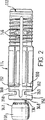
図2は、本発明による締結要素およびそのスリーブの側面図である。
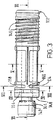
図3は、締結要素の縦軸を中心に90°回転した、図2の締結要素およびスリーブを示す。
図4は、図3の線IV−IV上の断面図である。
図5は、図3の線V−V上の断面図である。
図6は、図3の線VI−VI上の断面図である。
図7は、図3の線VII−VII上の断面図である。
図8は、締付け要素の下からの斜視図である。
図9は、本発明による代替締付け要素の前面図である。
図10は、締付け要素の側面図である。
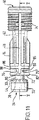
図11は、締付け要素と一緒に使用する代替締結要素およびスリーブを示す。
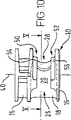
図12は、図10および図11の線V−Vに沿って見た締付け要素、締結要素およびスリーブの断面図である。
図13は、図12に対応する図で、締付け方向の最大回転位置にある締付け要素を示す。
図14は、図9の締付け要素の回転量と、このような回転によって生じた図11の細長い締結要素の軸方向の運動との関係を示すグラフである。
図2から図8を参照すると、接合部形成装置は、回転可能なドラム110の形態の締付け要素、細長いピン112の形態の締結要素、およびピン112のスリーブ114を備える。
図8に示す回転可能なドラム110は、開口116を有し、それを通ってピンの頭部分118をドラムの中心にある中空区域に挿入することができる。スロット120が開口116からドラムの周囲に円周方向に部分的に延在する。ドラムは2つの弓形カム表面122、124を規定し、これはスロット120によって互いから分離される。ドラムの上面126には、ドラムをねじ回しまたは六角レンチなどの手工具で回転できるよう、適切な手段(図示せず)を設ける。ピン112およびドラム110は、ピンを正確な位置に配置するため、最初に挿入すると、頭部分118がカム表面122と嵌合するよう設計することが好ましい。これは、ドラムの外周面166と嵌合するスリーブ114の前端148との組合せで生じることができる。
特に図6を参照すると、好ましくはダイカスト成形したピン112は、頭部分118、頭部分とは反対側のピンの端部に配置されたエキスパンダ部分、および頭部分とエキスパンダ部分との間に延在し、それを相互接続する胴134を備える。胴134は単純な円筒であり、エキスパンダ部分は、端と端とを接続した関係で配置された3つの円錐台部分136、138、140を備える。頭部分118が回転可能なドラム110の中空の内部に受容されると、カム表面122、124と協力するよう嵌合する凸状嵌合面142を備える。頭部分118はトロイド形であることが好ましい。
嵌合面142には、円周方向に間隔をあけてカム表面122、124、または特に好ましくはカム表面に設けた窪み(図示せず)と嵌合可能な複数の突起144を設けてもよい。突起および窪みを設けた場合、これはロック機構として働く。ロック機構の特徴に関するより詳細な記述については、出願人の英国特許第2246826号に注意されたい。
スリーブ114は、スリーブの対向する端部間に軸方向に延在する貫通穴を規定する、概ね環状の壁を備える。貫通穴は、一方端でピン112の円錐台136、138、140と対合するよう形成される。貫通穴の残りの部分は、ピンの胴134の周囲にぴったり適合するよう形成される。ピン112の前端およびエキスパンダ部分は、胴134を囲む貫通穴の部分より多少直径が大きいことが分かる。実際には、スリーブは、インサート成形として知られるプロセスによって、ピンに直接成形したプラスチック材料で作成することが考えられる。インサート成形は当業者には周知の技術であり、したがって本明細書ではこれ以上詳細には説明しない。あるいは、スリーブは、ピンの周囲で互いにスナップ留めする2つの部分を備えてもよく、その場合、スリーブの部分は蝶番式に接続することができる。
スリーブをピン112上に正しく適合させると、ピンの嵌合面142とスリーブの隣接する端面148との間にギャップがある。ドラム110とピン112とを組み付けると、嵌合面142と端面148との間のギャップに露出した胴134の部分を、ドラム・スロット120で受けることができる。これによって、ピンの頭部分118を中空の内部で受けた状態で、ドラムをその回転軸を中心に回転することができる。
ピンの円錐台部分136、138、140を収容するスリーブの端部では、スリーブの外表面に螺旋形に延在するかえし146を設け、スリーブと、かえしのある端部を受ける接合部材との間のグリップを改善させる。言うまでもなく、かえし146は螺旋形である必要はなく、当業者に周知のような同じ目的のため、スリーブにはどのような方法で突起を設けてもよい。
スリーブ114には圧壊手段を設け、これによってスリーブは縦方向に部分的に圧壊することができる。圧壊手段は、圧縮時のスリーブの強度を選択的に減少させるようになっている。
実施形態では、圧壊手段は、それぞれがスリーブの円周方向に部分的に延在する2つの対向する口150、および2つの十字形の口152の形態をとる。十字形の口152は、スリーブの対向する側に配置され、それぞれ縦方向に延在する部分を有し、これはほぼスリーブの全長にわたって延在する。
口150は、スリーブの(図2、図3および図6で見て)左側に配置され、十字形の口152の縦方向に延在する部分の左端とともに4つのリブ154を規定し、これはスリーブの輪のような前端部分156をスリーブの残りの部分と接続する。
十字形スロット152の横方向の部分158は2つの対向するリブ160を規定するよう配置され、これはリブ154と半径方向に偏り、半径方向でそれに対して概ね垂直に延在する。口150および十字形の口152は、その間に2つの弓形区画152を追加的に規定する。リブ160は、弓形区画162、リブ154および輪状の前端部分156をスリーブの残りの部分と接続する。この口、相互接続するリブおよび弓形区画の配置構成は、スリーブbの前端156に隣接する圧壊可能な領域を規定することが理解される。横方向の部分160からスリーブのかえし付きの端部まで縦方向に延在するスリーブの十字形の口152の部分も、わずかな程度ながら、スリーブの圧壊可能性に寄与していることも理解される。
使用時には、部材間に接合部を形成するため、図1aに示した既知の接合部形成装置の締結要素10、締付け要素12およびスリーブ24とほぼ同じ方法で、回転可能なドラム110、ピン112およびスリーブ114を、接合部材に設けた適切な凹部および内腔の中で互いに適合させる。締付け手順も同様にほぼ同じである。したがって、以下の記述では、2つの部材間に接合部を形成する実施形態の用法を、図1aに示した接合部材に関連させて述べ、接合部材およびその関連の内腔および凹部を指定するのに、同様の参照番号を使用する。
図1aの既知の装置と図2から8に示す装置との違いは、回転可能なドラム110のカム表面122、124がピン112の嵌合表面142と嵌合すると、スリーブの輪状前端部分156の端面148が、スロット120の両側のドラムの周辺面164、166と嵌合することである。これによって、ドラムに対するスリーブの軸方向の動きが防止され、したがってドラムを締付け方向に回転するにつれ、スリーブとピンとの間の相対的な動きがあり、これによって円錐台部分136、138がスリーブの軸方向内側に引っ張られ、スリーブのかえし付きの端部が半径方向に拡大する。
図1aに示した既知の配置構成に対するこの配置構成の一つの利点は、締付けプロセスの開始時に、嵌合表面142がカム表面142と嵌合した状態で、ピンの頭部分118が常に正確に配置されることであるのが理解される。これは、カム表面に対するピンの嵌合表面の初期位置が、ドラム110、ピン112およびスリーブ114の幾何学的形状によって決定されるせいである。これに対して図1aに示す既知の装置の場合は、接合部材20の端面36と、ドラムに設けた凹部18との間の距離によって決定される。したがって、ドラムが常に、カム表面とピンの嵌合表面との最適な嵌合が達成される位置に回転可能なので、良好な接合部が作成されることを保証することができる。
実施形態の接合部形成装置のさらなる利点は、スリーブ114の圧壊可能性によって獲得される。前述したように、ドラムの初期の引張り行為によってピンとスリーブとが相対的に移動し、その結果、スリーブのかえし付きの端部が強制的に凹部26の壁30と嵌合する。この位置に到達したら、ドラムをさらに回転すると、スリーブの圧縮力が生じ、リブ154、160の領域でスリーブが部分的に圧壊する。圧縮力が発生するのは、スリーブの位置がドラムの周辺面164、166と凹部の壁30との間に固定されているせいであり、スリーブが圧壊できなかった場合は、従来通りの手工具でドラムをさらに回転させることが、不可能ではないまでも、極めて困難になることが理解される。
スリーブの圧壊によってドラムがさらに回転すると、2つの利点がある。第1に、第2接合部材14と第1接合部材の端面36との間に何らかのギャップがあると、ピンをドラムの内側に引っ張るにつれ、ギャップが閉じる。第2に、スリーブの圧壊によって、2つの接合部材が、突き合わせた関係にある時にぴったり引き合わされ、接合部材が接合領域で圧縮される。
圧壊可能な手段は、実施形態で示す形態に制限されないことが理解される。例えば、1つの口または口のグループをスリーブに沿って間隔をあけて設け、複数の間隔をあけた圧壊可能な領域を規定することができる。
圧壊手段は、スリーブの壁に設けた口に制限されないことも理解される。例えば、薄い部分を規定する凹部をスリーブの壁に設け、それによってスリーブの圧壊可能性を高めることができる。
実施形態では、スリーブの前端部分156の位置は、ドラム110の回転軸に対して固定されたままである。スリーブがドラムに対して固定されたままであるので、締結要素は、スリーブを拡張するために、これに対して移動することができる。スリーブの位置をドラムの回転軸に対して固定するために、スリーブの前端はドラムの周辺に嵌合することが必須ではないことが理解される。
図9から図13を参照すると、2つの部材間に接合部を形成する接合部形成装置は、締付け要素10、ピン12の形態の締結要素、およびピンのスリーブ14を備える。締付け要素10は、ウェブ18によって相互接続される2つの概ね円筒形の部分15、16を備える円筒形のドラム様本体を有する。ドラム様本体は、ピン12の頭部分を受ける、中心に配置された空隙20、頭部分22を空隙20に挿入するのに通す概ね長方形の開口26、および本体の周囲に円周方向に延在するスロット28を規定する。スロット28は、使用時に締付け要素が、空隙20に受けた頭部分22と一緒に(図12および図13で見て)時計回りに回転すると、ピン12の首部分30を受けるようなサイズにする。
ねじ回しなどのような適切な工具で締付け要素を回転できるよう、本体部分15の(図9および図10で見て)最も外側の表面に適切な口を設ける。
ドラム様本体は、さらに、スロット28の各側に1つずつ配置された2つのカム表面32、34を規定する。カム表面32、34は、頭部分22の嵌合表面36と嵌合するようになっている。その縦方向で、カム表面は弓形の輪郭を有し、それは、頭部分22をカム表面32、34と嵌合させながら、締付け要素を時計回りに回転させると、ピン12が締付け要素の回転軸40に向かってその軸方向に移動するよう構成される。
カム表面の弓形輪郭の湾曲は、以下でさらに詳細に説明し、図14で示すように、締付け要素の回転量とピン12の軸方向の運動量との間に、このような運動の大部分にわたってほぼ線形の関係を提供するようになっている。
弓形の長さに対して横方向に、カム表面32、34は凹状であり、したがってピンの凸状、好ましくはトロイド形の嵌合表面36と接触する広範囲な表面を提供する。
カム表面32、34には、表面の長さに沿って間隔をあけた位置に複数の窪み42を設ける。窪み42は、嵌合表面36でほぼ間隔をあけた位置に設けた円錐形突起44と対合するよう形成される。窪み42と突起44との相互嵌合は、ラチェット様のロック機構を提供し、これは時計回りおよび反時計回りの方向で回転に対する抵抗を提供する。ロック機構の特徴に関するさらに詳細な説明については、本出願人の英国特許第2246826B号に注意されたい。
図12および図13を参照すると、ウェブ18は概ねU字形の断面を有し、比較的薄い壁によって規定されることが分かる。実施形態では、壁は0.4から1.0mmの範囲の厚さを有する。この形状は、ウェブの金属重量を大幅に削減し、それと同時に本体部分15、16を固定した間隔の関係に維持するのに必要な強度を提供する。
締付け要素の形成に使用する金属の量をさらに削減するため、円筒形の本体部分15、16は、本体部分15、16から突き出す個々のリブ54、56上にカム表面が規定されるよう、開口26の半径方向反対側で締付け要素の後部に位置する領域50、52を薄くする。
ウェブ18は、図13に示すように、締付け方向に締付け要素の限界を規定する。ウェブは、締付け要素が、ピンを開口に挿入した位置から225°である角度φだけ、回転軸40を中心に回転できるよう配置される。
締付け要素は、適切な亜鉛ダイカスト合金を使用し、ダイカスト法で形成することが好ましい。
ピン12はダイカスト成形品で、頭部分22、エキスパンダ部分60、および頭部分とエキスパンダ部分とを接続する胴62を備えることが好ましい。胴62は単純な円筒形であり、エキスパンダ部分60は、端と端とを接続した関係で配置された3つの円錐台部分64、66、68を備える。
ピン12のスリーブ14は、スリーブの対向する端部間に軸方向に延在する貫通穴を規定する、概ね環状の壁を備える。貫通穴は、一方端でピン112の円錐台部分64、66、68と対合するよう形成される。貫通穴の残りの部分は、ピンの胴62の周囲にぴったり適合するよう形成される。ピン12の頭部分およびエキスパンダ部分は、胴62を囲む貫通穴の部分より多少直径が大きいことが分かる。実際には、スリーブは、インサート成形として知られるプロセスによって、ピンに直接成形したプラスチック材料で作成することが考えられる。インサート成形は当業者には周知の技術であり、したがって本明細書ではこれ以上詳細には説明しない。あるいは、スリーブは、ピンの周囲で互いにスナップ留めする2つの部分を備えてもよく、その場合、スリーブの部分は蝶番式に接続することができる。
スリーブをピン上に正しく適合させると、ピンの嵌合面36とスリーブの隣接する端面74との間にギャップがある。このギャップに露出した胴62の部分が、ピン12の首部分30を規定する。
ピンの円錐台部分64、66、68を収容するスリーブの端部では、スリーブの外表面に螺旋形に延在するかえし74を設け、スリーブと、使用時にかえしのある端部を受ける接合部材との間のグリップを改善させる。言うまでもなく、かえし74は螺旋形である必要はなく、当業者に周知のような同じ目的のため、スリーブにはどのような方法で突起を設けてもよい。
スリーブ14には圧壊手段を設け、これによってスリーブは縦方向に部分的に圧壊することができる。圧壊手段は、圧縮時のスリーブの強度を選択的に減少させるようになっている。
実施形態では、圧壊手段は、それぞれがスリーブの円周方向に部分的に延在する2つの対向する口76、および2つの十字形の口78によって規定される。十字形の口78は、スリーブの対向する側に配置され、それぞれ縦方向に延在する部分を有し、これはほぼスリーブの全長にわたって延在する。
口76は、スリーブの(図11で見て)左側に配置され、十字形の口78の縦方向に延在する部分の左端とともに4つのリブ80を規定し、これはスリーブの輪のような前端部分82をスリーブの残りの部分と接続する。
十字形スロット78の横方向の部分84は2つの対向するリブ86を規定するよう配置され、これはリブ80に対して半径方向に偏り、半径方向でそれに対して概ね垂直に延在する。口76および十字形の口78は、その間に2つの弓形区画88を追加的に規定する。リブ86は、弓形区画88、リブ80および輪状の前端部分82をスリーブの残りの部分と接続する。この口、相互接続するリブおよび弓形区画の配置構成は、スリーブの前端72に隣接する圧壊可能な領域を規定することが理解される。横方向の部分84からスリーブのかえし付きの端部まで縦方向に延在するスリーブの十字形の口78の部分も、わずかな程度ながら、スリーブの圧壊可能性に寄与していることも理解される。
使用時には、部材間に接合部を形成するため、締付け要素10、ピン12およびスリーブ14を、接合部材に設けた適切な内腔および凹部中で互いに適合させる。さらに詳細に述べると、締付け要素を、第1接合部材の一方縁の主要面に形成され、接合部材の縁から所定の距離だけ間隔をあけた凹部に填める。締付け要素を収容する凹部は、凹部の軸に対して垂直に延在する内腔によって、第1接合部材の縁と連絡する。長方形の開口26を第1接合部材の内腔と整列させ、ピン12およびスリーブ14を内腔に挿入することにより、ピン12の頭部分22を、締付け要素の空隙20に挿入することができる。このように填めると、かえし74を設けたスリーブの端部が接合部材から突き出す。このスリーブ端部を、第2接合部材の縁に規定された凹部に押込嵌めし、これによって2つの部材間に緩やかな接合部を形成する。
2つの部材間の接合部を締め付けるため、締付け要素10を回転軸を中心に回転させ、カム表面32、34をピン12の嵌合表面36と嵌合させる。締付け要素をこのように回転させるにつれ、首30がスロット28に入り、スリーブ14の端面72がスロットのいずれかの側で締付け要素の周辺にもたれかかる。スリーブ14と締付け要素との嵌合により、締付け要素に対するスリーブの軸方向の運動が防止され、したがって締付け要素によってピンが回転軸40へと移動するにつれ、スリーブ14とピン12とが相対的に動くことになる。このピンとスリーブとの相対的な動きにより、円錐台部分64、66、68がスリーブの軸方向内側に引っ張られ、スリーブのかえし付き端部が半径方向に拡張する。十字形の口78がスリーブのかえし付き端部へと延長しているので、スリーブの拡張が容易になることが理解される。このスリーブの拡張により、スリーブおよびピン12が第2接合部材の凹部にしっかり取り付けられる。
締付け要素をさらに回転すると、スリーブに圧縮力が生じ、リブ80、86の領域でスリーブが部分的に圧壊する。圧縮力が発生するのは、スリーブの位置が第2接合部材の凹部と締付け要素の周辺との間に固定されているせいであり、スリーブが圧壊できなかった場合は、従来通りの手工具で締付け要素をさらに回転させることが、不可能ではないまでも、極めて困難になることが理解される。
スリーブ14の圧壊によってドラムがさらに回転すると、2つの利点がある。第1に、接合部材間に何らかのギャップがある場合、スリーブのかえし付き端部が拡張して第2接合部材の凹部に入ると、ギャップが閉じる。第2に、スリーブの圧壊によって、2つの接合部材が、突き合わせた関係にある時にぴったり引き合わされ、接合部材が接合領域で圧縮される。
図14は、締付け要素10の回転量と、このような回転によって生じたピン12の軸方向の運動との関係を示す。グラフの縦軸に沿って軸方向の運動量をmm単位で示し、横軸に沿って回転を度数で示す。回転と軸方向の運動との間の関係は、ピンの軸方向の運動の範囲を通してほぼ線形であることが分かる。実施形態では、締付け要素が締付け方向に10°回転するごとに、ピンは軸方向に約0.25mm動く。
これは、図1bに関して検討した従来の先行技術の締付け要素と比較して、ギア比が比較的小さく、したがって締付け要素を回転するために使用者が入力しなければならないトルクが小さくなる。これが好ましい実施形態であることが理解される。実際には、この「低トルク」効果を獲得するには、カム表面の弓形の輪郭を、10°回転するごとにピンの動きが0.3mm未満になるようにするとよいことが認識される。
弓形カム表面の湾曲を比較的浅くすることのさらなる利点は、嵌合表面とカム表面との嵌合のほぼ全てのポイントでロックアップが達成できることである。好ましい実施形態では、このロックアップが、確実な接合部を提供するために、窪み42と突起44との相互嵌合によって得られるロック機構によって強化される。
実施形態では、締付け要素の回転とピンの軸方向の運動との線形の関係が、ピンの運動のほぼ全範囲で存在する。実際には、範囲の両端でこの線形の関係から多少逸脱することがあるのが認識される。最高回転の位置では、成形プロセスのコアリングの問題により、カム表面の湾曲を変更する必要があることがある。頭部分22との嵌合が最初に発生するカム表面の反対側の端では、締付け表面を規定するリブがドラムの周辺で薄くなりすぎるのを防止するため、より急な曲線を提供する必要があることがある。しかし、カム要素の回転とピンの運動との間の線形の関係が、前記ピン運動の範囲の少なくとも75%にわたってあることが好ましい。
図1bおよび図14を参照すると、50〜70°の角度にわたって回転しなければ、カム表面とピンの頭部分との嵌合が発生しないことが分かる。この嵌合前の回転の範囲は、頭部分を締付け要素の中心空隙に挿入するのに通す開口の寸法、および締付け要素の周辺に対するカム表面の位置によって決定される。
スロット28を190°を超える回転が可能なように構成することにより、ピンの軸方向の運動範囲が、従来通りの締付け要素を使用して獲得されるのと同等の状態で、締付け要素10は線形のカム動作を提供することができ、必要な入力トルクが小さくなる。これは、締付け要素を実施形態のスリーブのような圧壊可能なスリーブと一緒に使用する場合に、特に有用である。これによって、スリーブのかえし付きの端部を拡張させ、スリーブの反対側の端部を圧壊させるのに十分な軸方向の運動を提供するよう、締付け要素を構成することができる。
締付け要素10および本明細書で述べた接合部形成装置は、接合部材の縁に対する締付け要素の凹部の配置に比較的広い範囲の不正確さがあっても、満足できる接合部を形成するよう機能することが理解される。したがって、締付け要素および接合部形成装置は、従来の締付け要素および接合部形成装置より許容値が大きいことを特徴とすることができる。The present invention relates to a joint forming apparatus, and more particularly to a joint forming apparatus that forms a joint between two members of a prefabricated furniture, but is not limited thereto.
Applicant's US Pat. No. 5,556,081 discloses a joint forming apparatus for forming a joint between two members. Referring to FIG. 1 of the drawings of the present application, a known joint forming device comprises an
The joint forming device further comprises a
In use, the
In order to form a joint between the two
If the tightening element is not correctly positioned with respect to the
The cam surfaces of known cam elements usually have a longitudinal profile that is adapted to provide a two-stage clamping action. FIG. 1 b is a graph showing the relationship between the rotation of the cam element and the axial movement of the fastening element in a conventional joint forming apparatus, and shows a two-stage tightening action. Axial movement is shown in mm along the vertical axis, and rotation is shown in degrees along the horizontal axis. In the first stage, a cam with a relatively steep or tight curve, ie a curve adapted to provide a relatively large amount of axial movement of the fastening element with a relatively small amount of rotation of the cam element The portion of the surface provides a relatively “rough movement” of the pin. The relationship between the rotation of the cam element and the axial movement caused thereby is non-linear and is typically greater than 0.5 mm per 10 ° rotation. This “coarse motion” is provided so that the gap between the two panels closes and presses together, and this motion is usually called pull-up. The second stage of pin motion is caused by the portion of the cam surface that has a relatively flat curve. The second stage movement increases the compressive force applied to the joint and locks the joint-forming device to some extent as the cam surface curvature decreases. This is usually called lockup. The more steep the cam surface curve is when it mates with the pin head, the more the cam element retracts, that is, in the direction opposite to the direction of rotation to tighten the joint when the panel to be used is loaded. It is understood that the possibility of rotation is high. Therefore, the cam element designed to provide the two-stage pin motion described above is joined to ensure a fit between the pin head portion and the flatter portion of the cam surface to ensure a so-called lock-up. It is intended to rotate fully during part tightening.
During use of the cam element according to FIG. 1b, the cam element is rotated approximately 50 ° from the position where the head portion of the pin is inserted into the hollow region until the cam surface mates with the head portion. The cam element must then rotate an additional 75 ° before a valid lock on the joint is obtained.
These conventional joint forming devices and cam elements have several drawbacks.
One drawback is that a relatively large rotational force is required to rotate the cam element during the pull-up phase. It will be appreciated that the cam is relatively “geared” during the pull-up phase, the steeper cam surface curve requires more torque input from the user. It is desirable to reduce the effort required of the user.
A further problem with this design is that the cam element has to be manufactured firmly to cope with the relatively large forces acting on it. If the cam element is not made strong, it may be destroyed by the load applied to it, and the phenomenon of cam destruction is well known to those skilled in the art.
It will be appreciated that such cam elements are typically produced in large quantities by die casting technology. Because die casting metals are relatively expensive, it is desirable to reduce the weight of metal required for each cam element as much as possible without significantly reducing strength.
A further disadvantage of the known joint forming device is that the tolerances are low. In other words, if the recesses and the lumens that are to be filled with the parts of the device are not accurately created, it may be impossible to form a reliable joint.
More specifically, in use, the cam element typically fills a recess in the major surface of the first joining member. This recess communicates with the edge by a lumen that breaks the edge of the panel or extends from the recess to the edge. This arrangement allows the head portion of the pin to be inserted into the cam element so that it can be mated with the cam surface when rotated on the cam element.
If the cam element is too close to the edge of the joining member, it turns out that it is impossible to tighten the joint. This is because only a small part of the length of each cam surface is effective during rotation of the clamping element. As a result, the fastening element only has a very small tensile force and the joint is less compressed and therefore the joint is weak.
If the cam element is too far from the edge of the joining member, the cam element can be rotated only a small amount in the clamping direction unless an undue amount of force is applied. In this case, it is not possible to rotate the cam element sufficiently for the head portion to fit into the portion of the cam that provides lockup, and the cam may rupture if it continues to rotate. As a result, the effective locking action is lost and the cam element tends to retract when the joint is loaded, resulting in a weak joint.
It is an object of the present invention to at least partially overcome the problems described above.
The present invention is an apparatus for forming a joint between two members, said apparatus comprising an elongated fastening element, a rotatable fastening element and a sleeve of said fastening element, said fastening element being a head portion of said fastening element At least one arcuate cam surface matable with the Tightening Its rotation about the axis of rotation of the element pulls the fastening element generally towards the axis of rotation so that the sleeve (i) remains in a fixed position with respect to the axis of rotation during use (i). And (ii) having an opposite end portion that is adapted to be easily expanded by the fastening element when pulled in this manner to secure the fastening element to such one joining member; (Iii) To provide a device that is partially collapsible in its longitudinal direction.
Preferably, the sleeve comprises a wall provided with a crushing means, whereby the sleeve is partially collapsible in its longitudinal direction.
The crushing means may comprise at least one thinned portion defined in the wall. The thin portion or each portion may define a groove extending in the longitudinal direction.
The crushing means may comprise at least one mouth defined in the wall. The mouth or each mouth may extend between the first and second end portions of the sleeve. The mouth or each mouth may be a cross-shaped mouth.
It is preferable that the peripheral surface of the cam element that can be fitted with the sleeve is arranged at an approximately equal distance in the radial direction from the rotation axis of the tightening element.
The present invention is an apparatus for forming a joint between two members, wherein the apparatus can be (i) rotatably attached to a first such joint member and has at least one arcuate cam surface. A fastening element and (ii) an elongated fastening element having a front end portion engageable with the cam surface or each of the surfaces, and thus an axis by which the fastening element is directed to the fastening element by the fastening element during use. A first end capable of causing directional movement and further comprising (iii) a sleeve of said fastening element, said sleeve being adapted to a recess of a second such joining member and cooperating with said fastening element And thus the axial movement forcibly mates with the wall of such a recess, causing a radial expansion of the first end portion of the sleeve and further If the front end portion fits the cam surface or each cam surface over the at least a significant portion of the rotational range of the fastening element when the mating surface and the cam surface are so fitted, the clamping An apparatus having a second end portion arranged to mate with a peripheral surface of the element is also provided.
For a full understanding of the present invention, embodiments of the invention will now be described with reference to the accompanying drawings, which are for illustrative purposes only.
FIG. 1a is a cross-sectional side view of a known joint forming apparatus disclosed in US Pat. No. 5,556,081.
FIG. 1b is a graph showing the relationship between the amount of rotation of the prior art clamping element and the axial movement of the elongated fastening element caused by such rotation.
FIG. 2 is a side view of a fastening element and its sleeve according to the invention.
FIG. 3 shows the fastening element and sleeve of FIG. 2 rotated 90 ° about the longitudinal axis of the fastening element.
4 is a cross-sectional view taken along line IV-IV in FIG.
5 is a cross-sectional view taken along line VV in FIG.
6 is a cross-sectional view taken along line VI-VI in FIG.
7 is a cross-sectional view taken along line VII-VII in FIG.
FIG. 8 is a perspective view from below of the clamping element.
FIG. 9 is a front view of an alternative clamping element according to the present invention.
FIG. 10 is a side view of the clamping element.
FIG. 11 shows an alternative fastening element and sleeve for use with a fastening element.
FIG. 12 is a cross-sectional view of the clamping element, the fastening element and the sleeve as viewed along line VV in FIGS. 10 and 11.
FIG. 13 corresponds to FIG. 12 and shows the clamping element in the maximum rotational position in the clamping direction.
FIG. 14 is a graph showing the relationship between the amount of rotation of the fastening element of FIG. 9 and the axial movement of the elongated fastening element of FIG. 11 caused by such rotation.
With reference to FIGS. 2-8, the joint forming apparatus comprises a clamping element in the form of a
The
With particular reference to FIG. 6, preferably a
The fitting surface 142 may be provided with a plurality of
The
When the sleeve is properly fitted over the
At the end of the sleeve that houses the
The
In an embodiment, the crushing means takes the form of two opposing
The
The transverse portion 158 of the
In use, in order to form a joint between the members, the
The difference between the known device of FIG. 1a and the device shown in FIGS. 2-8 is that when the
One advantage of this arrangement over the known arrangement shown in FIG. 1a is that the pin head portion 118 is always correctly positioned with the mating surface 142 mating with the cam surface 142 at the beginning of the clamping process. It is understood that this is done. This is because the initial position of the pin mating surface relative to the cam surface is determined by the geometry of the
A further advantage of the embodiment joint forming device is obtained by the crushability of the
There are two advantages to further rotation of the drum due to sleeve crushing. First, if there is any gap between the second joining
It is understood that the collapsible means is not limited to the form shown in the embodiments. For example, a single mouth or group of mouths may be spaced along the sleeve to define a plurality of spaced apart collapsible regions.
It is also understood that the crushing means is not limited to the mouth provided in the sleeve wall. For example, a recess defining a thin portion may be provided in the sleeve wall, thereby increasing the likelihood of the sleeve being crushed.
In the embodiment, the position of the
With reference to FIGS. 9 to 13, a joint forming device for forming a joint between two members comprises a clamping
A suitable mouth is provided on the outermost surface (as seen in FIGS. 9 and 10) of the
The drum-like body further defines two
The curvature of the arcuate contour of the cam surface is described in more detail below and, as shown in FIG. 14, between the amount of rotation of the clamping element and the axial momentum of the
Transversely to the arcuate length, the cam surfaces 32, 34 are concave, thus providing a wide range of surfaces in contact with the convex, preferably toroidal,
The cam surfaces 32, 34 are provided with a plurality of
Referring to FIGS. 12 and 13, it can be seen that the
In order to further reduce the amount of metal used to form the clamping element, the
The
The clamping element is preferably formed by a die casting method using a suitable zinc die casting alloy.
The
The
When the sleeve is properly fitted over the pin, there is a gap between the
At the end of the sleeve that houses the
The
In an embodiment, the crushing means is defined by two opposing
The
The
In use, the clamping
To tighten the joint between the two members, the clamping
Further rotation of the clamping element creates a compressive force on the sleeve and causes the sleeve to partially collapse in the region of the
If the drum rotates further due to the collapse of the
FIG. 14 shows the relationship between the amount of rotation of the clamping
This has a relatively small gear ratio and therefore less torque that the user must input to rotate the tightening element compared to the prior art prior art tightening element discussed with respect to FIG. 1b. It is understood that this is a preferred embodiment. In practice, it will be appreciated that to achieve this “low torque” effect, the arcuate contour of the cam surface should be such that the pin movement is less than 0.3 mm after every 10 ° rotation.
A further advantage of having a relatively shallow bow cam surface curvature is that lock-up can be achieved at almost any point of mating surface to cam surface mating. In a preferred embodiment, this lockup is enhanced by a locking mechanism obtained by the inter-fit of the
In an embodiment, a linear relationship between the rotation of the clamping element and the axial movement of the pin exists in almost the full range of pin movement. In practice, it will be appreciated that there may be some deviation from this linear relationship at both ends of the range. At the highest rotational position, cam surface curvature may need to be altered due to coring problems in the molding process. At the opposite end of the cam surface where mating with the
Referring to FIGS. 1b and 14, it can be seen that the rotation of the cam surface and the head portion of the pin does not occur unless rotated through an angle of 50-70 °. The range of rotation prior to mating is determined by the size of the opening through which the head portion is inserted into the central cavity of the clamping element and the position of the cam surface relative to the periphery of the clamping element.
By configuring the
The clamping
Claims (10)
Applications Claiming Priority (5)
| Application Number | Priority Date | Filing Date | Title |
|---|---|---|---|
| GBGB9704985.2A GB9704985D0 (en) | 1997-03-11 | 1997-03-11 | Joint forming devices |
| GB9704985.2 | 1997-03-11 | ||
| GB9708955.1 | 1997-05-01 | ||
| GBGB9708955.1A GB9708955D0 (en) | 1997-03-11 | 1997-05-01 | Camming element for joint forming devices |
| PCT/GB1998/000723 WO1998040634A1 (en) | 1997-03-11 | 1998-03-05 | Joint forming device |
Publications (2)
| Publication Number | Publication Date |
|---|---|
| JP2001524185A JP2001524185A (en) | 2001-11-27 |
| JP4339932B2 true JP4339932B2 (en) | 2009-10-07 |
Family
ID=26311159
Family Applications (1)
| Application Number | Title | Priority Date | Filing Date |
|---|---|---|---|
| JP53935598A Expired - Fee Related JP4339932B2 (en) | 1997-03-11 | 1998-03-05 | Joint forming device |
Country Status (11)
| Country | Link |
|---|---|
| US (1) | US6276868B1 (en) |
| EP (1) | EP0970311B1 (en) |
| JP (1) | JP4339932B2 (en) |
| CN (1) | CN1123702C (en) |
| AT (1) | ATE250187T1 (en) |
| AU (1) | AU6508798A (en) |
| BR (1) | BR9806695A (en) |
| DE (2) | DE69818237D1 (en) |
| DK (1) | DK0970311T3 (en) |
| ES (1) | ES2206902T3 (en) |
| WO (1) | WO1998040634A1 (en) |
Families Citing this family (21)
| Publication number | Priority date | Publication date | Assignee | Title |
|---|---|---|---|---|
| US6886286B2 (en) * | 2001-08-10 | 2005-05-03 | Samuel F. Dowding | Method of attaching the stock of a firearm to a frame |
| US7223045B2 (en) * | 2001-09-26 | 2007-05-29 | Agostino Ferrari S.P.A. | Device and method for detachably connecting abutting structural parts and tie member for use to form said device |
| DE20118279U1 (en) | 2001-11-09 | 2002-01-31 | Haefele Gmbh & Co | Link between two components |
| DE20120256U1 (en) * | 2001-12-14 | 2002-03-07 | Haefele Gmbh & Co | fitting |
| GB2383392B (en) * | 2001-12-18 | 2004-09-15 | Titus Int Plc | Improvements in fastening devices |
| US6946715B2 (en) * | 2003-02-19 | 2005-09-20 | Micron Technology, Inc. | CMOS image sensor and method of fabrication |
| GB2430991B (en) * | 2005-10-07 | 2008-09-10 | Titus Int Plc | Improvements in joint forming devices |
| US20070113484A1 (en) * | 2005-11-23 | 2007-05-24 | Mcgregor Jean T | Modular assembly system |
| US20070113495A1 (en) * | 2005-11-23 | 2007-05-24 | Roberts John F | Modular assembly system |
| DE102006024265B3 (en) * | 2006-05-24 | 2008-01-10 | Festool Gmbh | Fitting device for connecting two furniture parts |
| US20080075528A1 (en) * | 2006-09-22 | 2008-03-27 | Michael Marzetta | Construction system |
| GB2443425B (en) * | 2006-11-01 | 2010-11-03 | Titus Int Plc | Improvements in fasteners |
| GB2443424B (en) * | 2006-11-01 | 2010-10-27 | Titus Int Plc | Improvements in fasteners |
| US7824141B2 (en) * | 2007-08-03 | 2010-11-02 | Newfrey Llc | Blind rivet |
| CN201162746Y (en) * | 2007-09-21 | 2008-12-10 | 深圳何群家具有限公司 | Eccentric combiner (I) |
| TWI455239B (en) * | 2008-03-14 | 2014-10-01 | Lam Res Corp | Cam lock electrode clamp |
| US10495125B2 (en) * | 2014-12-12 | 2019-12-03 | Titus D.O.O. Dekani | Joint forming devices |
| ITUA20162145A1 (en) * | 2016-03-31 | 2017-10-01 | Effegi Brevetti Srl | JUNCTION DEVICE PERFORMED FOR FURNITURE PARTS AND FURNISHINGS |
| US10722029B2 (en) * | 2017-04-20 | 2020-07-28 | David O. Boone Revocable Trust | Framed full access cabinet |
| GB2564080A (en) * | 2017-04-25 | 2019-01-09 | Titus D O O Dekani | Improvements in joint forming devices |
| DE202019101077U1 (en) * | 2019-02-25 | 2019-04-02 | Häfele Berlin Gmbh & Co Kg | spreading connectors |
Family Cites Families (10)
| Publication number | Priority date | Publication date | Assignee | Title |
|---|---|---|---|---|
| DE2625182C3 (en) * | 1976-03-11 | 1980-06-19 | Richard Heinze Gmbh & Co Kg, 4900 Herford | Fitting for the detachable connection of two components, in particular panel-shaped components for furniture |
| GB2246826B (en) * | 1990-08-07 | 1993-08-04 | Titus Int Ltd | Fastening devices |
| DE9216182U1 (en) * | 1992-11-27 | 1993-01-21 | Haefele Gmbh & Co., 7270 Nagold, De | |
| GB2285106B (en) * | 1993-12-23 | 1997-07-16 | Titus Int Ltd | Joint forming device |
| ATE168172T1 (en) * | 1994-11-04 | 1998-07-15 | Lautenschlaeger Mepla Werke | CONNECTION FITTING |
| GB2301412B (en) * | 1995-05-31 | 1999-03-10 | Titus Int Plc | A housing for joint forming devices |
| GB2301413B (en) * | 1995-05-31 | 1999-03-10 | Titus Int Plc | Joint forming devices |
| GB2301643B (en) * | 1995-05-31 | 1999-06-23 | Titus Int Plc | Joint forming devices |
| GB2301644B (en) * | 1995-05-31 | 1999-03-10 | Titus Int Plc | Joint forming devices |
| US5823700A (en) * | 1996-09-18 | 1998-10-20 | Bush Industries, Inc. | Drawer front fastener |
-
1998
- 1998-03-05 BR BR9806695-1A patent/BR9806695A/en not_active IP Right Cessation
- 1998-03-05 WO PCT/GB1998/000723 patent/WO1998040634A1/en active IP Right Grant
- 1998-03-05 DK DK98910861T patent/DK0970311T3/en active
- 1998-03-05 EP EP98910861A patent/EP0970311B1/en not_active Expired - Lifetime
- 1998-03-05 CN CN98801383.5A patent/CN1123702C/en not_active Expired - Fee Related
- 1998-03-05 AU AU65087/98A patent/AU6508798A/en not_active Abandoned
- 1998-03-05 DE DE69818237T patent/DE69818237D1/en not_active Expired - Lifetime
- 1998-03-05 US US09/308,138 patent/US6276868B1/en not_active Expired - Lifetime
- 1998-03-05 ES ES98910861T patent/ES2206902T3/en not_active Expired - Lifetime
- 1998-03-05 DE DE19881663T patent/DE19881663C2/en not_active Expired - Fee Related
- 1998-03-05 AT AT98910861T patent/ATE250187T1/en not_active IP Right Cessation
- 1998-03-05 JP JP53935598A patent/JP4339932B2/en not_active Expired - Fee Related
Also Published As
| Publication number | Publication date |
|---|---|
| JP2001524185A (en) | 2001-11-27 |
| CN1123702C (en) | 2003-10-08 |
| EP0970311B1 (en) | 2003-09-17 |
| ES2206902T3 (en) | 2004-05-16 |
| BR9806695A (en) | 2000-02-29 |
| WO1998040634A1 (en) | 1998-09-17 |
| EP0970311A1 (en) | 2000-01-12 |
| DE19881663T1 (en) | 1999-11-18 |
| DE19881663C2 (en) | 2003-04-10 |
| DK0970311T3 (en) | 2004-01-26 |
| AU6508798A (en) | 1998-09-29 |
| DE69818237D1 (en) | 2003-10-23 |
| US6276868B1 (en) | 2001-08-21 |
| CN1254400A (en) | 2000-05-24 |
| ATE250187T1 (en) | 2003-10-15 |
Similar Documents
| Publication | Publication Date | Title |
|---|---|---|
| JP4339932B2 (en) | Joint forming device | |
| US5567081A (en) | Joint forming device | |
| US6547477B1 (en) | Connecting fitting | |
| US5846039A (en) | Positive lock rivet | |
| KR100436463B1 (en) | Straddling dowel | |
| US6276867B1 (en) | Joint forming devices | |
| CN110121602A (en) | The device for torque-limiting with holding claws | |
| HU178157B (en) | Lock pin having metal sleeve | |
| US20070160418A1 (en) | Quick assembly bolt jacket | |
| US5286151A (en) | Blind fastener | |
| US4566832A (en) | Sleeve-shaped expansion dowel | |
| JP2004003667A (en) | Fixing ring fitting device and its method | |
| US6186695B1 (en) | Dowels for securing objects to walls | |
| CA2066800C (en) | Expansible fastening device | |
| US5906453A (en) | Joint forming devices | |
| US20040013491A1 (en) | Anchor and nut assembly | |
| JPH10110475A (en) | Anchor metal fixture | |
| JP2000154810A (en) | Bolt with slip-off preventing function and fixing structure of member | |
| JP6231506B2 (en) | Anchor bolt | |
| EP0154466A1 (en) | Bolt anchor | |
| JPH10159185A (en) | Anchor fitting | |
| KR200225575Y1 (en) | Nut assembly | |
| EP1787032B1 (en) | Self-drilling anchor | |
| JPH10110476A (en) | Anchor metal fixture | |
| JPS62113906A (en) | Anchor |
Legal Events
| Date | Code | Title | Description |
|---|---|---|---|
| A621 | Written request for application examination |
Free format text: JAPANESE INTERMEDIATE CODE: A621 Effective date: 20050304 |
|
| RD04 | Notification of resignation of power of attorney |
Free format text: JAPANESE INTERMEDIATE CODE: A7424 Effective date: 20050304 |
|
| A131 | Notification of reasons for refusal |
Free format text: JAPANESE INTERMEDIATE CODE: A131 Effective date: 20071204 |
|
| A601 | Written request for extension of time |
Free format text: JAPANESE INTERMEDIATE CODE: A601 Effective date: 20080303 |
|
| A602 | Written permission of extension of time |
Free format text: JAPANESE INTERMEDIATE CODE: A602 Effective date: 20080414 |
|
| A521 | Request for written amendment filed |
Free format text: JAPANESE INTERMEDIATE CODE: A523 Effective date: 20080530 |
|
| A131 | Notification of reasons for refusal |
Free format text: JAPANESE INTERMEDIATE CODE: A131 Effective date: 20090127 |
|
| A521 | Request for written amendment filed |
Free format text: JAPANESE INTERMEDIATE CODE: A523 Effective date: 20090414 |
|
| TRDD | Decision of grant or rejection written | ||
| A01 | Written decision to grant a patent or to grant a registration (utility model) |
Free format text: JAPANESE INTERMEDIATE CODE: A01 Effective date: 20090609 |
|
| A01 | Written decision to grant a patent or to grant a registration (utility model) |
Free format text: JAPANESE INTERMEDIATE CODE: A01 |
|
| A61 | First payment of annual fees (during grant procedure) |
Free format text: JAPANESE INTERMEDIATE CODE: A61 Effective date: 20090703 |
|
| R150 | Certificate of patent or registration of utility model |
Free format text: JAPANESE INTERMEDIATE CODE: R150 |
|
| FPAY | Renewal fee payment (event date is renewal date of database) |
Free format text: PAYMENT UNTIL: 20120710 Year of fee payment: 3 |
|
| FPAY | Renewal fee payment (event date is renewal date of database) |
Free format text: PAYMENT UNTIL: 20130710 Year of fee payment: 4 |
|
| R250 | Receipt of annual fees |
Free format text: JAPANESE INTERMEDIATE CODE: R250 |
|
| R250 | Receipt of annual fees |
Free format text: JAPANESE INTERMEDIATE CODE: R250 |
|
| R250 | Receipt of annual fees |
Free format text: JAPANESE INTERMEDIATE CODE: R250 |
|
| R250 | Receipt of annual fees |
Free format text: JAPANESE INTERMEDIATE CODE: R250 |
|
| LAPS | Cancellation because of no payment of annual fees |