JP4339700B2 - System and method for improved material processing using laser beams - Google Patents
System and method for improved material processing using laser beams Download PDFInfo
- Publication number
- JP4339700B2 JP4339700B2 JP2003579692A JP2003579692A JP4339700B2 JP 4339700 B2 JP4339700 B2 JP 4339700B2 JP 2003579692 A JP2003579692 A JP 2003579692A JP 2003579692 A JP2003579692 A JP 2003579692A JP 4339700 B2 JP4339700 B2 JP 4339700B2
- Authority
- JP
- Japan
- Prior art keywords
- laser beam
- cornea
- computer
- pattern
- tissue
- Prior art date
- Legal status (The legal status is an assumption and is not a legal conclusion. Google has not performed a legal analysis and makes no representation as to the accuracy of the status listed.)
- Expired - Fee Related
Links
Images


Classifications
-
- A—HUMAN NECESSITIES
- A61—MEDICAL OR VETERINARY SCIENCE; HYGIENE
- A61F—FILTERS IMPLANTABLE INTO BLOOD VESSELS; PROSTHESES; DEVICES PROVIDING PATENCY TO, OR PREVENTING COLLAPSING OF, TUBULAR STRUCTURES OF THE BODY, e.g. STENTS; ORTHOPAEDIC, NURSING OR CONTRACEPTIVE DEVICES; FOMENTATION; TREATMENT OR PROTECTION OF EYES OR EARS; BANDAGES, DRESSINGS OR ABSORBENT PADS; FIRST-AID KITS
- A61F9/00—Methods or devices for treatment of the eyes; Devices for putting-in contact lenses; Devices to correct squinting; Apparatus to guide the blind; Protective devices for the eyes, carried on the body or in the hand
- A61F9/007—Methods or devices for eye surgery
- A61F9/008—Methods or devices for eye surgery using laser
- A61F9/00825—Methods or devices for eye surgery using laser for photodisruption
- A61F9/00827—Refractive correction, e.g. lenticle
-
- A—HUMAN NECESSITIES
- A61—MEDICAL OR VETERINARY SCIENCE; HYGIENE
- A61F—FILTERS IMPLANTABLE INTO BLOOD VESSELS; PROSTHESES; DEVICES PROVIDING PATENCY TO, OR PREVENTING COLLAPSING OF, TUBULAR STRUCTURES OF THE BODY, e.g. STENTS; ORTHOPAEDIC, NURSING OR CONTRACEPTIVE DEVICES; FOMENTATION; TREATMENT OR PROTECTION OF EYES OR EARS; BANDAGES, DRESSINGS OR ABSORBENT PADS; FIRST-AID KITS
- A61F9/00—Methods or devices for treatment of the eyes; Devices for putting-in contact lenses; Devices to correct squinting; Apparatus to guide the blind; Protective devices for the eyes, carried on the body or in the hand
- A61F9/007—Methods or devices for eye surgery
- A61F9/008—Methods or devices for eye surgery using laser
- A61F9/00825—Methods or devices for eye surgery using laser for photodisruption
- A61F9/00836—Flap cutting
-
- A—HUMAN NECESSITIES
- A61—MEDICAL OR VETERINARY SCIENCE; HYGIENE
- A61F—FILTERS IMPLANTABLE INTO BLOOD VESSELS; PROSTHESES; DEVICES PROVIDING PATENCY TO, OR PREVENTING COLLAPSING OF, TUBULAR STRUCTURES OF THE BODY, e.g. STENTS; ORTHOPAEDIC, NURSING OR CONTRACEPTIVE DEVICES; FOMENTATION; TREATMENT OR PROTECTION OF EYES OR EARS; BANDAGES, DRESSINGS OR ABSORBENT PADS; FIRST-AID KITS
- A61F9/00—Methods or devices for treatment of the eyes; Devices for putting-in contact lenses; Devices to correct squinting; Apparatus to guide the blind; Protective devices for the eyes, carried on the body or in the hand
- A61F9/007—Methods or devices for eye surgery
- A61F9/008—Methods or devices for eye surgery using laser
- A61F2009/00861—Methods or devices for eye surgery using laser adapted for treatment at a particular location
- A61F2009/00872—Cornea
-
- A—HUMAN NECESSITIES
- A61—MEDICAL OR VETERINARY SCIENCE; HYGIENE
- A61F—FILTERS IMPLANTABLE INTO BLOOD VESSELS; PROSTHESES; DEVICES PROVIDING PATENCY TO, OR PREVENTING COLLAPSING OF, TUBULAR STRUCTURES OF THE BODY, e.g. STENTS; ORTHOPAEDIC, NURSING OR CONTRACEPTIVE DEVICES; FOMENTATION; TREATMENT OR PROTECTION OF EYES OR EARS; BANDAGES, DRESSINGS OR ABSORBENT PADS; FIRST-AID KITS
- A61F9/00—Methods or devices for treatment of the eyes; Devices for putting-in contact lenses; Devices to correct squinting; Apparatus to guide the blind; Protective devices for the eyes, carried on the body or in the hand
- A61F9/007—Methods or devices for eye surgery
- A61F9/008—Methods or devices for eye surgery using laser
- A61F2009/00897—Scanning mechanisms or algorithms
Landscapes
- Health & Medical Sciences (AREA)
- Ophthalmology & Optometry (AREA)
- Heart & Thoracic Surgery (AREA)
- Vascular Medicine (AREA)
- Optics & Photonics (AREA)
- Surgery (AREA)
- Engineering & Computer Science (AREA)
- Biomedical Technology (AREA)
- Physics & Mathematics (AREA)
- Nuclear Medicine, Radiotherapy & Molecular Imaging (AREA)
- Life Sciences & Earth Sciences (AREA)
- Animal Behavior & Ethology (AREA)
- General Health & Medical Sciences (AREA)
- Public Health (AREA)
- Veterinary Medicine (AREA)
- Laser Surgery Devices (AREA)
- Laser Beam Processing (AREA)
- Glass Compositions (AREA)
Abstract
Description
(発明の分野)
本発明は、一般に、レーザビームを用いる材料プロセシングの分野に関し、そしてより具体的には、これらの材料の改善されたプロセシングのためのシステムおよび方法に関する。本発明は、作用の機構としてレーザ光破壊を利用する材料プロセシングのために、特に有用であり、特に、このようなプロセシングが、材料の表面上または表面下に配置された複数のレーザパルスの使用に関与する場合に、有用である。本発明の分野は、非常に広範であるが、本発明は、レーザビームを利用して、材料の内部に、一連の重なった光破壊された領域を形成し、新たな内部表面を規定するための、システムおよび方法として特に有用である。この結果、材料の前部分が移動され、材料の新たな内部表面へのアクセスを有し得る。この適用の特定の例は、角膜の外側層の少なくとも一部を除去することによって、患者の視力を補正するための、眼の手術の型においてである。新たな内部表面を、角膜組織の内部に作製することによって、この手順は、下にある内部角膜組織を露出させ、この組織が、角膜を再成形するため、および患者の視力を改善するために、変更され得る。
(Field of Invention)
The present invention relates generally to the field of material processing using laser beams, and more specifically to systems and methods for improved processing of these materials. The present invention is particularly useful for material processing that utilizes laser light breakdown as a mechanism of action, and in particular, such processing uses multiple laser pulses placed on or below the surface of the material. Useful when involved in. Although the field of the present invention is very broad, the present invention utilizes a laser beam to form a series of overlapping photodisrupted regions within a material to define a new internal surface. It is particularly useful as a system and method. As a result, the front portion of the material can be moved and have access to the new internal surface of the material. A specific example of this application is in the type of eye surgery for correcting patient vision by removing at least a portion of the outer layer of the cornea. By creating a new internal surface inside the corneal tissue, this procedure exposes the underlying internal corneal tissue so that the tissue can reshape the cornea and improve patient vision Can be changed.
(発明の背景)
3つの主要なクラスのレーザ−材料相互作用が存在する:光凝固、光アブレーション、および光破壊。光凝固は、吸収材料標的に適用される連続波レーザ光を使用し、その効果は、熱損傷の一次効果および二次効果によって、媒介される。この技術は、網膜の疾患(例えば、糖尿病性網膜症および筋肉変性)を処置するために、眼において最も広範に使用されている。光アブレーションにおいて、非常に吸収性の紫外波長が、表面の材料を蒸発させるため(特に、表面エッチングおよび角膜における屈折率手術適用のため)に使用される。
(Background of the Invention)
There are three main classes of laser-material interactions: photocoagulation, photoablation, and photodisruption. Photocoagulation uses continuous wave laser light applied to the absorbing material target, the effect of which is mediated by the primary and secondary effects of thermal damage. This technique is most widely used in the eye to treat retinal diseases such as diabetic retinopathy and muscle degeneration. In photoablation, highly absorbing ultraviolet wavelengths are used to evaporate surface material (especially for surface etching and refractive index surgical applications in the cornea).
光破壊は、レーザ誘導光学分解(LIOB)で開始し、ここで、レーザパルスが、高強度の電場を発生させ、遊離電子およびイオンの混合物(これは、プラズマ状態を構成する)の形成を導く。ホットプラズマは、膨張して、周囲の材料を押しのける。プラズマの膨張が遅くなると、この押しのけの前面は、衝撃波として材料を通って伝播される。この衝撃波は、伝播するにつれてエネルギーおよび速度を失い、通常の音波に緩和される。断熱的に膨張するプラズマは、迅速に再結合し、そして冷却し、最終的に、キャビテーション気泡を形成する。キャビテーション気泡の構成は、標的材料の構成に依存する。眼の基質については、キャビテーション気泡は、主として、CO2、N2およびH2Oから構成される。 Photodisruption begins with laser-induced optical decomposition (LIOB), where a laser pulse generates a high-intensity electric field that leads to the formation of a mixture of free electrons and ions (which constitutes a plasma state). . The hot plasma expands and pushes away surrounding materials. As the plasma expands slowly, the displacement front is propagated through the material as a shock wave. This shock wave loses energy and velocity as it propagates and is relaxed to normal sound waves. The adiabatically expanding plasma quickly recombines and cools, eventually forming cavitation bubbles. The configuration of the cavitation bubbles depends on the configuration of the target material. The substrates of the eye, the cavitation bubbles is mainly composed of CO 2, N 2 and H 2 O.
光破壊レーザおよび送達システムを使用して、局在した光破壊が、材料の表面またはその下に配置されて、非常に正確な材料プロセシングを生じ得る。このような材料プロセシングの1つの例において、複数のパルスを予め決定された経路に配置することによって、内部表面が、材料の内部に作製され得る。特定の場合において、これらの表面は、水平方向、垂直方向または斜め方向の効果を生じるように、任意の配向で配置される面として表され得る。 Using a photodisruption laser and delivery system, localized photodisruption can be placed at or below the surface of the material, resulting in very accurate material processing. In one example of such material processing, an internal surface can be created inside the material by placing multiple pulses in a predetermined path. In certain cases, these surfaces can be represented as planes that are arranged in any orientation to produce a horizontal, vertical or diagonal effect.
光破壊レーザの使用において、種々の結果が、気体、細片、および他の光破壊副生成物の性質から生じ得る。いくつかの材料において、光破壊は、気体および水蒸気の形成を生じる。これらおよび他の副生成物の挙動および影響は、これらを囲む材料の特徴、および引き続いて近隣に配置されるさらなるレーザパルスの影響に依存する。一般に、気泡は、大きさが、最小の抵抗の領域内へと膨張する。膨張とともに、気体は冷却され、そして成分気体(例えば、水蒸気)は、液体状態に戻り得る。さらなるレーザパルスが配置されている領域における光破壊の間に発生する気体、液体、細片および他の副生成物の存在は、可変の結果または所望でない結果の原因であり得る。本発明は、これらの潜在的な影響に対する排除または軽減のストラテジーを与えることによって、レーザ光破壊を利用する先行技術に対する改善を提示する。 In the use of photodisruption lasers, various results can arise from the nature of gases, strips, and other photodisruption byproducts. In some materials, photodisruption results in the formation of gas and water vapor. The behavior and influence of these and other by-products depends on the characteristics of the material surrounding them and the influence of further laser pulses subsequently placed in the vicinity. In general, the bubble expands into a region of minimal resistance. With expansion, the gas is cooled and the component gas (eg, water vapor) can return to the liquid state. The presence of gases, liquids, debris and other by-products generated during photodisruption in the area where the further laser pulse is located can be the cause of variable or undesirable results. The present invention presents an improvement over the prior art that utilizes laser photodisruption by providing an elimination or mitigation strategy for these potential effects.
本発明の特定の適用は、視覚の誤差を補正するための、眼の手術手順における角膜層の作製のための、光破壊レーザの使用においてである。視覚障害は、多くの理由により起こり得、そして多くの原因の結果であり得る。視覚障害に対する1つの共通の原因は、眼の欠損状態から生じ、これは、角膜の屈折特徴が、光の平行な光線を網膜に集束させない場合におこる。眼が休止しており、そして光の光線が網膜の前方で集束する場合、この状態は、近視(myopia)(すなわち、近視(near−sightedness))として公知である。他方で、光の光線が網膜の後方で集束する場合、この状態は、遠視(hypermetropia)または遠視(hyperopia)(すなわち、遠視(farsightedness))として公知である。近視状態と遠視状態との両方が、様々な程度の視覚の障害を生じる。ほとんどの場合において、これらの状態は、矯正可能である。 A particular application of the present invention is in the use of a photodisruptive laser for the production of a corneal layer in an ophthalmic surgical procedure to correct visual errors. Visual impairment can occur for many reasons and can be the result of many causes. One common cause for visual impairment arises from an ocular defect, which occurs when the refractive features of the cornea do not focus parallel rays of light onto the retina. If the eye is at rest and the ray of light is focused in front of the retina, this condition is known as myopia (ie, near-sightedness). On the other hand, when the light beam is focused behind the retina, this condition is known as hypermetropia or hyperopia (ie farsightedness). Both myopic and hyperopic conditions produce varying degrees of visual impairment. In most cases, these conditions can be corrected.
眼鏡またはコンタクトレンズは、近視状態または遠視状態を補正するために、通常使用される。しかし、種々の理由により、これらの状態に悩まされる多くの人は、眼鏡もコンタクトレンズも着用したがらない。これらの状態を補正するための代替の様式としては、角膜を種々の様式で再形成するための、公知の手術手順が挙げられ、これらは、角膜の屈折特徴を変化させるのに効果的である。例えば、L’Esperanceに対する米国特許第4,665,913号および同第4,669,466号において、角膜組織を、眼の前表面から光アブレーションするレーザシステムが記載されている。別の手順は、Billeに対する米国特許第4,988,348号に記載されており、これによって、角膜組織がまず除去されて視力を補正され、次いで、新たに作製された表面が平滑にされる。 Glasses or contact lenses are usually used to correct myopia or hyperopia. However, for various reasons, many people suffering from these conditions do not want to wear glasses or contact lenses. Alternative ways to correct these conditions include known surgical procedures for reshaping the cornea in various ways, which are effective in changing the refractive characteristics of the cornea . For example, U.S. Pat. Nos. 4,665,913 and 4,669,466 to L'Esperance describe laser systems that photoablate corneal tissue from the anterior surface of the eye. Another procedure is described in US Pat. No. 4,988,348 to Bille, which first removes corneal tissue to correct vision and then smoothes the newly created surface. .
屈折欠陥を補正するために、眼の前部分の一部を除去および再形成するのではなく、内部の支質組織を除去するための、支質内光破壊と称される技術を使用して、他の手順が開発された。このような手順およびレーザシステムの例は、Billeらに対する米国特許第4,907,586号、およびJuhaszらに対する米国特許第5,993,438号に記載されている手順である。支質組織を除去するための手順の別の例は、Juhaszに対する米国特許第6,110,166号に記載されている。この手順において、前角膜層は、レーザを使用して、一連の重なった光破壊された領域を作製することによって、規定され得る。次いで、医師は、角膜層を持ち上げることによって分離し、下にある角膜組織へのアクセスを得、この角膜組織の形状を、光アブレーションレーザ(例えば、エキシマレーザ)を用いて変化させる。次いで、この角膜層は、核膜上に再配置される。 Using a technique called intrastromal photodisruption to remove internal stromal tissue rather than removing and reshaping part of the anterior portion of the eye to correct refractive defects Other procedures were developed. Examples of such procedures and laser systems are those described in US Pat. No. 4,907,586 to Bille et al. And US Pat. No. 5,993,438 to Juhasz et al. Another example of a procedure for removing stroma tissue is described in US Pat. No. 6,110,166 to Juhasz. In this procedure, the anterior corneal layer can be defined by using a laser to create a series of overlapping photodisrupted regions. The physician then separates by lifting the corneal layer, gaining access to the underlying corneal tissue, and changing the shape of the corneal tissue using a photoablation laser (eg, an excimer laser). This corneal layer is then repositioned on the nuclear membrane.
以前の実施において、医師は、レーザビームを、形成されるべき角膜層の中心またはその近くの開始位置に集束させることによって、角膜層を作製する。このレーザビームは、開始位置において組織の領域の光破壊を開始し、そして予め決定された経路に沿って、代表的にスパイラルのパターンで、角膜層の中心から、角膜層の予め決定された周囲へと移動される。最後に、レーザビームは、予め決定された周囲の周りに指向され、角膜層から角膜の外側表面への外周切断を形成する。 In previous implementations, the physician creates the corneal layer by focusing the laser beam to a starting position at or near the center of the corneal layer to be formed. This laser beam initiates photodisruption of the region of tissue at the starting location and from the center of the corneal layer, in a spiral pattern, along a predetermined path, to a predetermined circumference of the corneal layer Moved to. Finally, the laser beam is directed around a predetermined perimeter, forming a perimeter cut from the corneal layer to the outer surface of the cornea.
いくつかの場合において、レーザビームを予め決定された経路またはパターンに沿って移動させることによって、一時的に曇った外観を生じることが観察されている。これは、光破壊プロセスの間に作製される、組織の内部に拡散する気体および/または細片の結果であると考えられる。なぜなら、これらの気体および細片のための出口が存在しないからである。この状態は、一時的である;気体および/または細片は、最終的に、数分後に、周囲の組織に吸収される。この状態は、有意な副作用を有さないが、気体の拡散は、高品質の内部表面を作製する際に、予め決定された経路に配置されるさらなるレーザの有効性に、影響を与え得る。曇った外観と、レーザパルスを確実にするさほど有効でない効果との両方が、望ましくないと考えられる。 In some cases, it has been observed that moving the laser beam along a predetermined path or pattern produces a temporarily cloudy appearance. This is believed to be the result of gases and / or debris diffusing inside the tissue that are created during the photodisruption process. Because there are no outlets for these gases and strips. This condition is temporary; the gas and / or debris will eventually be absorbed into the surrounding tissue after a few minutes. Although this condition has no significant side effects, gas diffusion can affect the effectiveness of additional lasers placed in a predetermined path in creating a high quality internal surface. Both the cloudy appearance and the less effective effect of ensuring laser pulses are considered undesirable.
いくつかの場合および状況において、レーザビームを予め決定されたパターンに沿って移動させることは、流体を生じることもまた、観察された。この流体は、組織中に拡散し得、そして高品質の内部表面を作製する際に予め決定された経路に配置されるさらなるレーザパルスの有効性に影響を与え得る。この流体は、表面の不規則性を生じ得、これは、新たに作製された内部表面の平滑さを減少させる。 In some cases and situations, it has also been observed that moving the laser beam along a predetermined pattern produces fluid. This fluid can diffuse into the tissue and can affect the effectiveness of additional laser pulses placed in a predetermined path in creating a high quality internal surface. This fluid can create surface irregularities that reduce the smoothness of the newly created internal surface.
従って、気体および細片を組織中に拡散させず、上記流体の発生も拡散も導かない(これらの両方は、予め決定された経路に沿って配置されたさらなるパルスの特徴および有効性を変化させる)、予め決定された経路またはパターンに対する必要性が認められている。代替として、これらの気体および/または流体の影響が排除され得ない場合でさえも、これらの負の二次的効果の影響はまた、特定の予め決定された経路を選択することによって、軽減され得る。さらに、これらの所望の光破壊パターンおよび予め決定された経路を実施するための、方法およびシステムに対する必要性が存在する。 Thus, gas and debris do not diffuse into the tissue and do not lead to the generation or diffusion of the fluid (both of which alter the characteristics and effectiveness of additional pulses placed along a predetermined path) ), The need for a predetermined route or pattern is recognized. Alternatively, even if the effects of these gases and / or fluids cannot be eliminated, the effects of these negative secondary effects are also mitigated by selecting a specific predetermined path. obtain. Furthermore, there is a need for methods and systems to implement these desired photodisruption patterns and predetermined paths.
望ましいパターンまたは予め決定された経路の特定の例は、一次のパターンまたは予め決定された経路に接続されるかまたは隣接した、二次のパターンまたは予め決定された経路の作製を包含する。このレザバは、任意の型のパターン切断からの副生成物および/または気体の影響を制御し得る。さらに、レザバを実施するための方法およびシステムに対する必要性が存在する。このようなレザバと組み合わせて、または代替のアプローチとして、一次または二次のパターンまたは予め決定された経路における、特定のレーザパルスの配置および特徴は、任意の型のパターン切断からの副生成物および/または気体の影響を制御するように選択され得る。 Specific examples of desirable patterns or predetermined paths include the creation of secondary patterns or predetermined paths that are connected to or adjacent to the primary pattern or predetermined path. This reservoir can control the effects of by-products and / or gases from any type of pattern cutting. Furthermore, there is a need for a method and system for implementing a reservoir. In combination with such a reservoir, or as an alternative approach, the placement and characteristics of a particular laser pulse in a primary or secondary pattern or predetermined path may be a by-product from any type of pattern cutting and It may be selected to control the influence of the gas.
(発明の要旨)
本発明により、光破壊レーザを使用する、改善された材料プロセシングのための方法およびシステムが開発された。この方法は、レーザビームを、材料の表面、またはその上方もしくは下方の開始位置に指向する工程、ならびにその後、このレーザビームを、この開始位置から、好ましい予め決定された経路に沿って移動させ、さらなるレーザパルスが配置される領域における光破壊の間に生じる気体、細片および他の副生成物の影響を減少または軽減する工程を包含する。
(Summary of the Invention)
In accordance with the present invention, methods and systems have been developed for improved material processing using photodisruptive lasers. The method directs the laser beam to a surface of the material, or a starting position above or below it, and then moves the laser beam from the starting position along a preferred predetermined path; Including reducing or mitigating the effects of gases, debris and other by-products that occur during photodisruption in the region where the additional laser pulses are located.
本発明の1つの実施形態において、好ましい予め決定された経路は、材料のより重要な領域における光破壊の間に生じる気体、細片および他の副生成物の影響を減少または軽減する材料の特定の領域における開始位置を有する。この実施形態の例として、予め決定された経路は、材料の表面または内部に配置されたパターンの周囲で開始し、パターンの中心における光破壊の間に生じる気体、細片および他の副生成物の影響を減少または軽減させ得る。この実施形態の例としては、焦点を、スパイラルパターン中の予め決定された経路に沿って移動させることを包含する。このスパイラルパターンは、内部表面の予め決定された周囲で開始し、そしてこの予め決定された周囲の中心に向かって延びる。別の実施形態において、この予め決定された経路は、ラスターパターンの形状である。このラスターパターンは、材料を通って、前後に延びる予め決定された周囲の近くの開始位置から、この予め決定された周囲の反対側の方へと延びる。第三の実施形態において、レーザビームの焦点は、一連の同心円の形状の予め決定された経路に沿って移動され、この経路は、予め決定された外周またはその近くの開始位置から、この予め決定された周囲の中心の方へと延びる。これらの実施形態は、光破壊の開始時に生じる気体、細片および他の副生成物の影響を、パターンの周囲に局在させるが、開始位置をパターンの中心に選択することによって、逆の効果が選択され得る。 In one embodiment of the invention, the preferred predetermined path is the identification of a material that reduces or reduces the effects of gases, debris and other by-products that occur during photodisruption in more important areas of the material. With a starting position in the region. As an example of this embodiment, the predetermined path starts around the pattern placed on or in the surface of the material, and gas, debris and other by-products generated during photodisruption at the center of the pattern Can reduce or mitigate the effects of An example of this embodiment includes moving the focus along a predetermined path in the spiral pattern. The spiral pattern begins at a predetermined perimeter of the inner surface and extends toward the center of the predetermined perimeter. In another embodiment, the predetermined path is a raster pattern shape. The raster pattern extends through the material from a starting position near a predetermined perimeter that extends back and forth toward the opposite side of the predetermined perimeter. In a third embodiment, the focal point of the laser beam is moved along a predetermined path of a series of concentric circles, which path is determined from this predetermined starting position at or near the outer periphery. Extending toward the center of the perimeter. These embodiments localize the gas, debris and other by-product effects that occur at the beginning of photodisruption around the pattern, but the opposite effect is achieved by selecting the starting position at the center of the pattern. Can be selected.
本発明の別の実施形態において、材料プロセシングは、一次の予め決定された経路に接続または隣接する、二次パターン(その独自の好ましいパターンまたは予め決定された経路を有する)の作製によって影響を受け得る。一次の予め決定された経路における光破壊の間に生じる気体、細片および他の副生成物は、これらのいわゆるレザバの作製による、さらなるレーザパルス配置の領域から、有意に減少または排除され得る。 In another embodiment of the present invention, material processing is affected by the creation of a secondary pattern (having its own preferred pattern or predetermined path) that is connected to or adjacent to the primary predetermined path. obtain. Gases, debris and other byproducts generated during photodisruption in the primary predetermined path can be significantly reduced or eliminated from the area of further laser pulse placement due to the creation of these so-called reservoirs.
本発明の別の実施形態において、作製される二次パターンの効果は、一次パターンのものとは異なり得る、特定の幾何学的構造および内部レーザパルス特徴を選択することによって、最適化され得る。これらとしては、面積、深度、レーザのパルスからパルスまでの距離(スポット分離)、およびエネルギーが挙げられる。 In another embodiment of the present invention, the effect of the created secondary pattern can be optimized by selecting specific geometric structures and internal laser pulse features that can differ from those of the primary pattern. These include area, depth, laser pulse-to-pulse distance (spot separation), and energy.
本発明の別の実施形態において、材料プロセシングはまた、材料に天然に存在するレザバによって影響を受け得る(これらのレザバが、一次の予め決定された経路での光破壊の間に生じた気体、細片および他の副生成物の収集を可能にする場合)。二次のパターンまたは経路は、これらの天然に存在するレザバに接続するように作製され得、ここで、一次のパターンまたは経路に対する影響は、これらの接続パターンについての特定の幾何学的構造および内部レーザパルス特徴(これらは、一次パターンのものとは異なり得る)の選択によって、影響を受ける。これらとしては、面積、深度、レーザのパルスからパルスまでの距離(スポット分離)、およびエネルギーが挙げられる。 In another embodiment of the present invention, material processing can also be affected by reservoirs that are naturally present in the material (the gasses generated during photodisruption in the primary predetermined pathway, To allow collection of strips and other by-products). Secondary patterns or pathways can be created to connect to these naturally occurring reservoirs, where the effects on the primary pattern or pathway are specific geometric structures and internals for these connection patterns It is influenced by the selection of laser pulse characteristics (these can be different from those of the primary pattern). These include area, depth, laser pulse-to-pulse distance (spot separation), and energy.
本発明の別の実施形態において、効果的に作動するレザバの存在下で、一次のパターンまたは予め決定された経路の特定のレーザパルス特徴は、さらなるレーザパルスの配置の領域における光破壊の間に生じる気体、細片および他の副生成物の影響を減少または軽減するように選択され得る。これらとしては、面積、深度、レーザのパルスからパルスまでの距離(スポット分離)、およびエネルギーが挙げられる。 In another embodiment of the present invention, in the presence of an effectively working reservoir, the specific laser pulse features of the primary pattern or predetermined path may be reduced during photodisruption in the region of further laser pulse placement. It can be selected to reduce or mitigate the effects of the resulting gas, debris and other by-products. These include area, depth, laser pulse-to-pulse distance (spot separation), and energy.
材料が、眼の角膜であり、そして目的が、角膜層の作製である場合、予め決定された経路は、支質組織を通って延び、角膜層を規定する。前部の内部表面が、前部の内部表面と角膜周辺との間のヒンジありまたはなしで、形成され得る。一次の予め決定された経路の開始位置は、角膜の外側表面の下、または角膜の外側表面上のいずれかに位置し得る。予め決定された経路は、一次の予め決定された周囲が、種々の形状(例えば、ほぼ円形またはほぼ楕円形)で形成されるように、成形され得る。一次の予め決定された経路はまた、前部の内部表面がほぼ平坦であるか、ほぼ凸状であるか、ほぼ凹状であるか、または下にある前部の表面の下方の組織における任意のエキシマレーザアブレーションの形状にほぼ適合するような形状であるように、成形され得る。 If the material is the cornea of the eye and the purpose is the creation of the corneal layer, the predetermined pathway extends through the stromal tissue and defines the corneal layer. The anterior interior surface can be formed with or without a hinge between the anterior interior surface and the cornea periphery. The starting position of the primary predetermined pathway can be located either below the outer surface of the cornea or on the outer surface of the cornea. The predetermined path can be shaped such that the primary predetermined perimeter is formed in a variety of shapes (eg, approximately circular or approximately oval). The primary predetermined path may also be any surface in the tissue below the front surface that is substantially flat, generally convex, substantially concave, or underneath the front surface. It can be shaped to be a shape that closely matches the shape of the excimer laser ablation.
本発明の別の局面は、予め決定された周囲を有する角膜の内部表面を露出することに関する。この方法は、支質組織の一連の重なる光破壊された領域を形成して、角膜層を形成することによるものであり、この角膜層は、前表面および後表面を有する。この角膜層は、少なくとも部分的に、核膜から取り外し可能である。この方法は、レーザビームの焦点を、内部表面の予め決定された周囲の近隣の開始位置に配置し、次いで、予め決定された経路に沿って開始位置からレーザビームの焦点を移動する工程、およびこの経路に沿って組織を光破壊し、重なる領域のパターンを、露出されるべき内部表面にわたって作製して、角膜層を形成する工程、およびこの角膜層の少なくとも一部を除去して、角膜の内部表面を露出させる工程を包含する。本発明のこの局面のさらなる実施形態は、本明細書中に記載されるものと類似している。 Another aspect of the invention relates to exposing the inner surface of the cornea having a predetermined perimeter. This method is by forming a series of overlapping photodisrupted regions of stromal tissue to form a corneal layer, which has a front surface and a back surface. This corneal layer is at least partially removable from the nuclear membrane. The method places the focal point of the laser beam at a starting location near a predetermined perimeter of the interior surface, and then moves the focal point of the laser beam from the starting location along a predetermined path; and Photodisrupting the tissue along this path, creating a pattern of overlapping regions over the internal surface to be exposed to form a corneal layer, and removing at least a portion of the corneal layer to Exposing the internal surface. Further embodiments of this aspect of the invention are similar to those described herein.
この方法はまた、角膜の外側表面の後部の内部表面からある角度で延びる、外周表面を形成する工程を包含し得る。この外周表面は、レーザビームの焦点を移動させ、そして前部の内部表面の近隣から角膜の外側表面まで延びる経路に沿った複数の点において、組織を光破壊することによって形成される。1つの実施形態において、外周表面は、後部の内部表面に対して90°以上の角度で形成され、一方で、別の実施形態において、外周表面は、後部の内部表面に対して90°以下の角度で形成される。 The method may also include forming an outer peripheral surface that extends at an angle from the posterior inner surface of the outer surface of the cornea. This peripheral surface is formed by moving the focal point of the laser beam and photodisrupting the tissue at multiple points along the path extending from the vicinity of the front inner surface to the outer surface of the cornea. In one embodiment, the outer peripheral surface is formed at an angle of 90 ° or more with respect to the rear inner surface, while in another embodiment, the outer peripheral surface is 90 ° or less with respect to the rear inner surface. Formed at an angle.
角膜層の作製の場合において、レーザパルスが配置される界面における気体は、2つの表面の間の分離の、断続的な領域を作製し得る。この界面における液体は、不均一な表面を作製し得る。前者は、形成する気泡に隣接する水平位置において抵抗が高く、角膜における空間を通って角膜中に気体を拡散させ、外来の気泡を生じる場合に起こり得る。抵抗が、形成する気泡に隣接する水平位置において低い場合、気体が水平方向に拡散し、そして外来の気泡は見られない。後者は、抵抗が、形成する気泡に隣接する水平位置において非常に低く、その結果、気体が非常に迅速に拡散し、水蒸気の急激な冷却および濃縮を導く場合に起こり得る。次いで、この流体は、レーザパルスが配置されている領域の界面にしみて戻り得る。レーザパルスが配置されている領域の界面における流体の存在は、局所的な深度の変化および大きい特徴の表面異常(例えば、リッジおよび波)の発生を生じ得る。 In the case of the production of the corneal layer, the gas at the interface where the laser pulse is placed can create an intermittent region of separation between the two surfaces. Liquid at this interface can create a non-uniform surface. The former can occur when the resistance is high at the horizontal position adjacent to the bubble to be formed, and gas is diffused through the space in the cornea into the cornea, resulting in foreign bubbles. If the resistance is low in the horizontal position adjacent to the bubbles that form, the gas diffuses horizontally and no foreign bubbles are seen. The latter can occur when the resistance is very low in the horizontal position adjacent to the bubbles that form, so that the gas diffuses very quickly, leading to rapid cooling and concentration of the water vapor. This fluid can then return to the interface of the region where the laser pulse is located. The presence of fluid at the interface of the region where the laser pulse is located can result in the occurrence of local depth variations and large feature surface anomalies (eg, ridges and waves).
角膜層の作製の場合において、レザバまたは二次的なパターンもしくは予め決定された経路は、以下のパラメータで最適化されて、気泡を減少させ得、そして角膜層の形成を改善し得る(より大きいレザバ面積、より大きい深度、より高いレーザパルスエネルギー、およびより近いスポット分離)。パルスが配置される領域の流体の影響を小さくするために、上記スキームの逆が実施され得る。 In the case of corneal layer production, the reservoir or secondary pattern or predetermined path can be optimized with the following parameters to reduce bubbles and improve corneal layer formation (greater than Reservoir area, greater depth, higher laser pulse energy, and closer spot separation). The inverse of the above scheme can be implemented to reduce the effect of fluid in the region where the pulse is located.
角膜層の作製の場合、一次のパターンまたは予め決定された経路(すなわち、平坦な切断)の特定のレーザパルス特徴は、気泡を減少させ(そして角膜層形成を改善し):スポット分離およびレーザパルスエネルギーを減少させるように、最適化され得る。パルスが配置される領域における流体の影響を減少させるために、上記スキームの逆が実施され得る。 For the creation of the corneal layer, certain laser pulse features of the primary pattern or predetermined path (ie, flat cut) reduce bubbles (and improve corneal layer formation): spot separation and laser pulse It can be optimized to reduce energy. The reverse of the above scheme can be implemented to reduce the effect of fluid in the area where the pulse is placed.
角膜層の作製の場合、後部の内部表面から角膜の外周へと、角膜−強膜接合部(縁)の方へと延びるレザバおよび/または接続が形成され得る。このレザバは、後表面に対して任意の角度であり得、そして任意の外周のために伸長し得るか、または任意の形状を有し得る。このレザバは、気体/液体および細片の蓄積の制御を補助する。さらに、レザバは、組織の分離/切除特徴に影響を与える。また、レザバは、特定の幾何学的形状についての作製される表面の特徴/品質、および意図される表面(これは、気体および細片を、除去可能な層の中心部分において捕捉させない)の深度の位置に、影響を与える。本明細書中のレザバは、角膜組織の文脈で議論されるが、レザバは、他の組織または非生物学的材料において利用されて、一次光破壊切断が作製される位置での細片の除去を補助し得る。 For the production of the corneal layer, reservoirs and / or connections can be formed that extend from the inner surface of the rear part to the outer periphery of the cornea and towards the cornea-sclera junction (edge). The reservoir can be at any angle with respect to the back surface and can extend for any circumference or have any shape. This reservoir helps control gas / liquid and strip accumulation. In addition, the reservoir affects tissue separation / ablation characteristics. The reservoir is also the feature / quality of the created surface for a particular geometry and the depth of the intended surface (which does not allow gas and debris to be trapped in the central portion of the removable layer). Affects the position of Although the reservoirs herein are discussed in the context of corneal tissue, the reservoirs are utilized in other tissues or non-biological materials to remove debris at the location where the primary photodisruptive cut is made. Can help.
本発明はまた、本明細書中に記載される工程を実施するための、ソフトウェアが実装されたコンピュータ読取り可能媒体を包含する。眼の手術システムの場合において、レーザビームを指向して、所望のパターンおよびレーザパルス特徴を生じるための、コンピュータシステムが提供される。このシステムは、予め決定された経路の選択をユーザから受信するための、入力制御デバイス、予め決定された経路の選択を格納するためのメモリ、入力制御デバイスおよびメモリに結合されたプロセッサユニットであって、ユーザによって入力された情報を処理して、選択された予め決定された経路を同定し、そして選択された予め決定された経路に沿って、レーザビームの移動を制御する工程を実施するための、プロセッサユニット、方法の進行を表示するための出力ディスプレイ、角膜表面または角膜表面下で、集束して上記材料を破壊する能力を有するレーザ源、ならびにプロセッサユニットおよび出力ディスプレイに接続される、レーザ源のための集束または指向機構を備える。 The present invention also includes software-implemented computer readable media for performing the processes described herein. In the case of an eye surgery system, a computer system is provided for directing a laser beam to produce a desired pattern and laser pulse characteristics. The system comprises an input control device for receiving a predetermined path selection from a user, a memory for storing the predetermined path selection, an input control device and a processor unit coupled to the memory. Processing the information entered by the user to identify the selected predetermined path and to implement the step of controlling the movement of the laser beam along the selected predetermined path A processor unit, an output display for displaying the progress of the method, a laser source capable of focusing and destroying the material under or on the corneal surface, and a laser connected to the processor unit and the output display A focusing or directing mechanism for the source is provided.
本発明はまた、フェムト秒レーザシステムを包含し、このシステムは、集束して、表面の上方または下方の材料を破壊する能力を有するレーザビームを発生させるためのレーザ源、および所望のパターンを作製するためにレーザを指向するためのプロセッサを備える。このシステムは、レーザビームの焦点を開始位置に指向する工程、この焦点を、予め決定された経路に沿って移動させ、その結果、光破壊の間に生じた気体、細片および他の副生成物の影響が、さらなるレーザパルスが配置されている領域において減少または軽減される工程を実施する。本発明の別の局面は、レーザビームを指向して、好ましい予め決定された経路を、材料の表面の上方または下方に作製するための、コンピュータによって実施される方法である。パターン切断のための幾何学的境界の選択は、ユーザによって選択されるか、またはファイルもしくはデータベースから読み出され、ソフトウェアによって受信され得、ここで、選択された幾何学的境界のパラメータが、メモリに格納される。幾何学的境界は、材料の映像の周りに表示される。材料の中心点は、材料の周りの境界を配向する際に使用するために、決定され得る。この配向は、最初、プログラムによって実施される;しかし、ユーザは、幾何学的境界を再配向し得る。パターン切断の型は、ユーザによって選択されるか、またはファイルもしくはデータベースから読み出され、そしてソフトウェアによって受信され、ここで、パターン切断の選択された型が、メモリに格納される。次いで、レーザビームが、選択された幾何学的境界について選択されたパターン切断を使用して、材料の光破壊を実施するように、指向される。この光破壊は、通常、深度の値に基づいて、材料表面の下方で起こる。とりわけ、パターンの型は、同心状、スパイラル、またはラスター状であり得る。光破壊は、材料の水平方向の切除を作製し得る。次いで、レーザビームは、この水平方向の切除の周囲の周りで、垂直方向の切除を作製するように指向され得る。垂直方向の切除が、幾何学的境界の周囲の全長に沿って作製されない場合、ヒンジが作製され得る。 The present invention also includes a femtosecond laser system that produces a laser source and a desired pattern for focusing and generating a laser beam that has the ability to destroy material above or below the surface. A processor for directing the laser to do so. The system directs the focal point of the laser beam to the starting position, moving the focal point along a predetermined path, resulting in gases, debris and other by-products generated during photodisruption. A process is performed in which the influence of the object is reduced or mitigated in the region where further laser pulses are arranged. Another aspect of the present invention is a computer-implemented method for directing a laser beam to create a preferred predetermined path above or below the surface of the material. The selection of geometric boundaries for pattern cutting can be selected by the user or read from a file or database and received by software, where the parameters of the selected geometric boundaries are stored in memory. Stored in Geometric boundaries are displayed around the image of the material. The center point of the material can be determined for use in orienting boundaries around the material. This orientation is initially performed by the program; however, the user can reorient the geometric boundary. The pattern cutting type is selected by the user or read from a file or database and received by software, where the selected type of pattern cutting is stored in memory. The laser beam is then directed to perform photodisruption of the material using the selected pattern cut for the selected geometric boundary. This photodisruption usually occurs below the material surface based on depth values. In particular, the pattern type can be concentric, spiral, or raster. Photodisruption can create a horizontal ablation of material. The laser beam can then be directed to create a vertical ablation around the periphery of this horizontal ablation. If a vertical cut is not made along the entire length around the geometric boundary, a hinge can be made.
本発明について意図される場合、この方法を達成するために使用されるレーザシステムは、連続レーザパルスのビームを組み込む。さらに、ビームにおけるレーザパルスの持続時間は、ナノ秒、ピコ秒、またはフェムト秒の範囲であることが企図される。 When intended for the present invention, the laser system used to accomplish this method incorporates a beam of continuous laser pulses. Further, it is contemplated that the duration of the laser pulse in the beam is in the nanosecond, picosecond, or femtosecond range.
(好ましい実施形態の説明)
図1を最初に参照すると、レーザビーム12を発生するための装置10が示される。レーザビーム12は、患者16の眼14に指向される。本発明の目的のために、装置10は、米国特許第4,764,930号(本発明の譲渡人に対して独占的に使用を許可される)に開示および特許請求されるようなレーザシステムによって発生されるレーザビームと類似する物理的特性を有する、パルスレーザビーム12を発生し得る。さらに、本発明は、数ナノ秒程度に長い持続時間または数フェムト秒程度に短い持続時間のパルスを有するパルス化されたレーザビーム12の使用を企図する。
(Description of Preferred Embodiment)
Referring initially to FIG. 1, an
1つの実施形態において、レーザユニットは、一定エネルギーのレーザビームを使用して、角膜の光破壊のためのソフトウェアによって制御され、このレーザビームは、数10万Hzまでの反復速度で、約600フェムト秒の持続時間を有するパルスの光学列から構成される。放出されたパルス列の実際のエネルギーは、ステッパー電動機制御下で作動する可変アテニュエーター(エネルギー減衰ホイール)を回転させることによって決定される。 In one embodiment, the laser unit is controlled by software for corneal photodisruption using a constant energy laser beam, which is approximately 600 femto at repetition rates up to several hundred thousand Hz. It consists of an optical train of pulses having a duration of seconds. The actual energy of the emitted pulse train is determined by rotating a variable attenuator (energy attenuation wheel) operating under the control of a stepper motor.
エネルギー測定デバイスは、アテニュエーターと安全シャッターとの間の光学経路に配置される。これらのデバイスは、光学的送達システムに移送されるエネルギーの一定部分を測定する。光学的送達システムは、関節化アーム、Z軸上昇、X軸並進およびY軸並進、X,Y,Z軸検流計スキャナー、望遠鏡、Z軸集束レンズ、チューニングミラー、顕微鏡および患者の眼と接触する使い捨てアプラネーション(applanation)レンズからなる。 The energy measuring device is placed in the optical path between the attenuator and the safety shutter. These devices measure a certain portion of the energy transferred to the optical delivery system. Optical delivery system includes articulating arm, Z-axis lift, X-axis translation and Y-axis translation, X, Y, Z-axis galvanometer scanner, telescope, Z-axis focusing lens, tuning mirror, microscope and patient eye contact It consists of a disposable applanation lens.
光学的送達システムは、レーザが集束される、患者の角膜における3次元位置を決定する。レーザがパルス化される場合、焦点に送達されるエネルギーは、非常に小さな容積中の組織をイオン化(光破壊)するために十分である。繰り返し焦点を設定し、そしてレーザをパルス化することを繰り返すことによって、組織の一部切除面を生じる。 The optical delivery system determines the three-dimensional position in the patient's cornea where the laser is focused. When the laser is pulsed, the energy delivered to the focal point is sufficient to ionize (photodestruct) tissue in a very small volume. By repeatedly setting the focus and pulsing the laser repeatedly, a partially excised surface of the tissue is produced.
図2は、眼14の解剖学的構造を示し、具体的には、角膜18が、瞳孔20、虹彩22、および強膜24の前方にあることを示す。さらに、図2は、眼14の光軸26が、角膜18を通過することを示す。結果として、角膜18の組織は、可視光に対して透明である。
FIG. 2 shows the anatomy of the
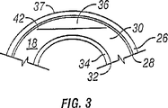
図3において、角膜18が、組織の解剖学的に定義できる5つの層を含むことが示され得る。図3において前から後の方向で進むと、角膜の組織の層は、以下である:上皮26、ボーマン膜28、支質30、デセメット膜32および内皮34。前部の内部表面35および後部の内部表面38は、所定の開始点42でレーザビームの焦点を集束することおよびレーザビームの焦点を開始点42から所定のパターンで支質組織を通って移動し、一連の重複光破壊領域を形成することによって、作製される。あるいは、角膜層36は、同様の様式において作製され得る。
In FIG. 3, it can be shown that the
図4は、前部の内部表面35または眼から部分的に除去された角膜層36を示す。角膜層36は、角膜の外表面である外表面37を有する。角膜層36は、眼から完全に除去され得るか、または図4に示されるように、ヒンジで結合されたままであり得る。図4に示されるように、角膜層36が、除去され、光アブレーションされる角膜の内部表面39を露出し得る。
FIG. 4 shows the anterior
レーザビームの移動のパターンは、本発明の1つの局面である。以前の実施において、図5を参照すると、外科医は、角膜層の中心付近に開始点42を選択し、あるパターン(例えば、スパイラル)にレーザビームを動かし、所定の周囲まで抜ける。しかし、上記されるように、いくつかの場合において、このパターンは、角膜層の中心に曇った出現物を生じ得ることが、観察される。曇った出現物は、レーザの使用の間生じる気体および細片の結果である。中心から周囲へのスパイラルパターンに起因して、この気体および細片は、角膜の内部に閉じ込められる。なぜなら、気体および細片に対する出口は、制限されるからである。この曇った出現物は、望ましくなく、そして配置されるさらなるレーザパルスの有効性を低下し得る。逆に、発生した気体が、作製されたまたは天然に存在するレザバへの通路を有する場合、流体は、さらなるレーザパルスが配置される領域に到達し得、それによって、組織分離に干渉し、平坦でない表面を導く。
The pattern of laser beam movement is one aspect of the present invention. In previous implementations, referring to FIG. 5, the surgeon selects a
本発明は、さらなるレーザパルスが、さらなるレーザパルスが配置される領域またはプロセシングを受けている物質の他の感受性領域における生成物によって、気体、流体、細片および他の副生成物の蓄積を最小にする。角膜の場合について図6を参照して、角膜層の所定の周囲43に実質的に近い、角膜の表面の下の開始点42を選択することおよびパターン(例えば、図6に示される周囲から中心へのスパイラルパターン、または図7に示されるラスターパターン、または図8に示される同心円パターン)に沿って終点44までレーザビームの焦点を動かすことによって、気体および細片の蓄積は、中心で最小化され、このことは、曇った出現物を減少する。角膜層36の所定の周囲43は、実質的に、円形または楕円形の形状をし得る。図は、パターンを形成する種々の実施形態を示す。示された図は、パターンを制限することを意味しない。
The present invention minimizes the accumulation of gases, fluids, debris and other by-products by products in the region where the additional laser pulse is located or other sensitive regions of the material being processed. To. Referring to FIG. 6 for the case of the cornea, selecting a
図8の同心円パターンにおいて、各同心円に対して別々の開始点が存在することに留意のこと。第1の開始点42は、角膜層の所定の周囲43に実質的に近い。レーザビームは、円形の経路に対して指向された後、第1の開始点42に実質的に近い終点46まで来る。次いで、レーザビームは、第2の開始点48に指向され、そして第2の終点50へと円形経路に沿って移動される。この第2の終点は、第2の開始点48に実質的に近い。このプロセスは、レーザビームが、最終開始点52に指向され、最終開始点52に実質的に近い最終終点44まで円形経路に沿って移動されるまで続く。
Note that there is a separate starting point for each concentric circle in the concentric pattern of FIG. The
所定の経路は、単一の面上にあり得るか、または前部の内部表面35または支質組織39の内部表面が、凹状または凸状であるような経路であり得る。
The predetermined path can be on a single plane or can be such that the front
レーザビームが所定の経路に沿って移動された後、レーザが、角膜層36の所定の周囲43のまわりの周辺表面45または前部の内部表面および角膜37の外側表面を角膜層36の前部の内部表面35に結合する後部の内部表面を形成するように指向される。図9aおよび9bにおいて破線によって示される周辺表面45を形成することは、レーザビームの焦点を使用し、角膜層または前部の内部表面および後部の内部表面の所定の周囲と角膜の外側表面との間に一連の重複する光破壊された領域を生成することによって達成され、そして周辺表面45が、後部の内部表面38に対して一定の角度であるように実施され得る。この角度は、90°を超える角度であり得、その結果、周辺表面45および後部の内部表面38は、ボール型を形成するか、またはこの角度は、90°未満であり得、その結果、周辺表面45および後部の内部表面38は、円錐型を形成する。90°より大きな角度を達成するために、レーザビームの焦点は、まず所定の周囲43のまわりに指向され、次いで、連続的にわずかにより大きな周囲の経路に対して指向され、角膜の外側表面の方に動かす。逆に、90°未満の角度を達成するために、レーザビームの焦点は、まず所定の周囲43のまわりに指向され、次いで、連続的にわずかにより小さな周囲の経路に対して指向され、角膜の外側表面の方に動かす。正確に90°の角度を達成するために、レーザビームの焦点は、まず所定の周囲43のまわりに指向され、次いで、全く同じ所定の周囲の経路に対して指向され、角膜の外側表面の方に動かす。
After the laser beam has been moved along the predetermined path, the laser passes the
周辺の表面45は、図9aに示されるように、全ての所定の周囲43のまわりに延長し得るか、または、図9bに示されるように、所定の周囲43のまわりに完全な回転を作成する前に中断され、角膜層36またはヒンジ54に結合される前部の内部表面35の部分を残し、フラップを形成する。周辺表面45を形成した後、外科医は、前部の内部表面35を除去し、後部の内部表面38を露出し、手順を完了し得る。本発明の代替的な局面において、外科医は、角膜層36を除去し、支質組織36の内部表面を露出し、手順を完了し得る。
The
一次パターンまたは所定の経路において、気体、流体、細片および他の副産物の蓄積をさらに減少するために、第2パターンまたはレザバは、一次パターンの周辺または隣に作製され、一次処置パターン由来の気体および細片の蓄積を可能にし得る。このレザバは、任意の形状およびサイズの主要なパターンの生成の前に、作成され得、好ましくは、直接または角膜中の天然に前もって存在するチャネルまたは潜在的なチャネルを介してのいずれかで、主要なパターンに結合されるべきである。気体および細片は、このレザバ中に蓄積され得るか、または眼の現存する経路を通って周辺に排出され得る。 In order to further reduce the accumulation of gases, fluids, strips and other by-products in the primary pattern or predetermined path, a second pattern or reservoir is created around or next to the primary pattern, and gas from the primary treatment pattern And allow accumulation of strips. This reservoir can be made prior to the generation of the main pattern of any shape and size, preferably either directly or via a naturally pre-existing channel or potential channel in the cornea, Should be combined with the main pattern. Gases and debris can accumulate in this reservoir or can be expelled to the surroundings through the existing path of the eye.
レザバと主要なパターンとの間の流体(気体)連絡を作製することは、好ましいが、必ずしも必要ではないかもしれない。天然のチャネルは、同じ目的を提供し得る。 Creating a fluid (gas) communication between the reservoir and the main pattern is preferred but may not be necessary. Natural channels can serve the same purpose.
一次パターンまたは所定の経路における気体、流体、細片および他の副産物の経路または非常に容易な経路を提供することはまた、所望されない効果を有し得る。なぜなら、流体は、レーザパルスが配置される領域において、干渉し得るからである。1つの実施形態において、レザバの最適な全面積は、一次パターン切断の全面積の約10%である。別の実施形態において、レザバ中のパルス間距離は、6ミクロンより大きく、パルスエネルギーは、8μJ未満である。別の実施形態において、主要なパターンとレザバとの間の小さな連結が、使用され得、このサイズは、有効性をさらに調節し得る。 Providing a primary pattern or a path of gases, fluids, strips and other by-products in a predetermined path or a very easy path may also have undesirable effects. This is because the fluid can interfere in the region where the laser pulse is located. In one embodiment, the optimal total area of the reservoir is about 10% of the total area of the primary pattern cut. In another embodiment, the interpulse distance in the reservoir is greater than 6 microns and the pulse energy is less than 8 μJ. In another embodiment, a small link between the main pattern and the reservoir can be used, and this size can further adjust the effectiveness.
排水の増加は、レザバ角の増加、レザバ直径の増加、およびレザバ深度の増加の関数である。排水に対する必要性の増加は、主要なパターンの切断の面積の増加、主要な切断のより浅い深度、および主要な切断におけるより高いパルスエネルギー(これは、より多くの気体を発生させる)の関数である。排水の制御を増大するために、レザバのサイズが、減少され、レザバの内部「抵抗性」は、パルスエネルギーを減少し、そしてスポット分離を増大することによって、増加される。 The increase in drainage is a function of an increase in reservoir angle, an increase in reservoir diameter, and an increase in reservoir depth. The increased need for drainage is a function of the increase in the area of the main pattern cut, the shallower depth of the main cut, and the higher pulse energy in the main cut (which generates more gas) is there. To increase drainage control, the reservoir size is reduced and the reservoir's internal “resistance” is increased by decreasing the pulse energy and increasing spot separation.
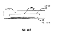
図10aおよび10bを参照して、レザバ62の1つの実施形態は、パターン切断60に隣接して形成されて示される。例示されるように、一次パターン60は、水平切除のためのラスターパターンとして作製される。しかし、他のパターンは、一次パターンのために使用され得る。レザバの特定の配置、幅、深度、および角度は、一次パターンの特定の寸法を収容するように作製される。レザバ62(ポケットとも呼ばれる)は、主パターン切断60に隣接して作製され、この例において、4.1mmの半径を有する。レザバの角度は、眼の中心点から120度である。レザバの幅は、第1のアークの位置64から第2のアークの位置65まで約300〜400μmである。好ましいポケット(レザバ)角度は、45〜90度であり、好ましい最大ポケット幅は、300ミクロンである。レザバ62は、好ましくは、最初に形成され、その後、主パターン切断を作製する。レザバの底は、角膜の表面から約160μmで示される。第2のアークの位置は、縁61に隣接して作製されるように示される。
With reference to FIGS. 10 a and 10 b, one embodiment of the
図11をここで参照して、レザバ71の別の実施形態は、パターン切断70に隣接して形成される。この実施形態において、水平切除70を囲む完全に360°のポケットが作製されるが、縁73の周囲内である。この実施例において、レザバの幅は、約100〜200μmで示される。好ましくは、レザバ71が最初に作製され、次いで、一次パターン70が作製されるべきである。
Referring now to FIG. 11, another embodiment of the reservoir 71 is formed adjacent to the pattern cut 70. In this embodiment, a full 360 ° pocket surrounding the
本発明の方法を実施するための1つの方法は、本明細書中に記載される方法を実施するために、レーザビームの焦点を方向付けるコンピューターシステムを備えるレーザユニットを提供することである。このコンピューターシステムは、本方法で使用される所定のパターンの選択のようなユーザからの情報を受け取るための入力コントロールデバイス、所定のパターンの選択を保存するためのメモリ、選択された所定のパターンを同定するためにユーザによって入力された情報を処理するための、入力コントロールデバイスおよびメモリに連結されたプロセッサユニット、本方法の進行を表示するための出力ディスプレー、角膜表面の下の組織に焦点を当て、破壊する能力を有するレーザ源、およびこのプロセッサユニットおよび出力ディスプレーに接続されたレーザ源のための焦点合わせ機構を備える。 One way to carry out the method of the present invention is to provide a laser unit with a computer system that directs the focus of the laser beam to perform the method described herein. The computer system includes an input control device for receiving information from a user, such as a selection of a predetermined pattern used in the method, a memory for storing a selection of the predetermined pattern, a selected predetermined pattern. Focuses on the input control device and processor unit coupled to the memory for processing information entered by the user for identification, the output display for displaying the progress of the method, and the tissue beneath the corneal surface. A focusing mechanism for the laser source capable of breaking, and a laser source connected to the processor unit and the output display.
本発明の方法を実施するための別の方法は、本明細書中に記載される方法を実施するために、レーザビームの焦点を方向付けるソフトウェアプログラムを提供することである。このようなソフトウェアプログラムの1つの実施形態は、入力コントロールデバイスおよび出力ディスプレーデバイスを作動可能なプログラムである。入力コントロールデバイスは、キーボード、マウス、タッチスクリーンまたはコンピュータとともに使用される他の入力デバイスであり得る。出力ディスプレーデバイスは、モニターまたはコンピュータースクリーンである。ソフトウェアプログラムは、レーザユニットの操作のためのデータおよびパラメーターを保存および検索するために、データベースと相互作用する。 Another way to implement the method of the present invention is to provide a software program that directs the focus of the laser beam to perform the method described herein. One embodiment of such a software program is a program capable of operating an input control device and an output display device. The input control device can be a keyboard, mouse, touch screen or other input device used with a computer. The output display device is a monitor or a computer screen. The software program interacts with the database to store and retrieve data and parameters for laser unit operation.
ソフトウェアプログラムは、種々の他の機能に加えて、パターン切断の幾何学的境界の選択または決定、角膜の幾何学的境界の配向、レーザビームの動きの向き、パターン切断の型の選択、およびさらなるパターンの選択を提供する。 The software program, in addition to various other functions, selects or determines the geometric boundary for pattern cutting, the orientation of the geometric boundary of the cornea, the direction of movement of the laser beam, the selection of the pattern cutting type, and further Provides a selection of patterns.
(パターンの幾何学的境界の決定)ソフトウェアプログラムは、水平切除の周囲についての規定された幾何学的境界を使用する。この境界は、水平切除パターンの外側境界を設定する。ソフトウェアアプリケーションは、標準の初期設定パターンとして、1つの幾何学的境界のみ(例えば、環状境界)を使用するように構成され得る。あるいは、このソフトウェアによって、レーザユニットの操作者が、1セットの利用可能な幾何学的境界から選択され得るように構成され得る。複数のパターンのセグメントは、レザバおよび排出経路の作製のために、特別なまたは不均一な幾何学的境界を作製するように組み合わされ得る。ユーザインターフェース(代表的には、ディスプレーモニター)は、ユーザに、角膜組織の水平切除のための利用可能な幾何学的境界の選択を提示する。操作者が異なる幾何学的境界を選択することを望む場合、ユーザは、水平切除のための異なる境界を選択する。例えば、ソフトウェアアプリケーションは、水平切除のための標準初期設定幾何学的形状として円を使用するように構成され得る。しかし、レーザユニットの操作者は、異なる境界(例えば、楕円形)が特定の患者についてより有利であり得ることを決定して、異なる幾何学的境界を選択し得る。 Determining the geometric boundary of the pattern The software program uses a defined geometric boundary around the horizontal ablation. This boundary sets the outer boundary of the horizontal ablation pattern. A software application may be configured to use only one geometric boundary (eg, an annular boundary) as a standard default pattern. Alternatively, the software can be configured so that the operator of the laser unit can be selected from a set of available geometric boundaries. Multiple pattern segments can be combined to create special or non-uniform geometric boundaries for the creation of reservoirs and discharge paths. A user interface (typically a display monitor) presents the user with a selection of available geometric boundaries for horizontal ablation of corneal tissue. If the operator wishes to select a different geometric boundary, the user selects a different boundary for horizontal ablation. For example, the software application may be configured to use a circle as a standard default geometry for horizontal ablation. However, the operator of the laser unit may select different geometric boundaries, determining that different boundaries (eg, ellipses) may be more advantageous for a particular patient.
(角膜上の幾何学的境界を配向させること)幾何学的境界は、患者の眼の画像上に表示される。この画像は、患者の眼の実際の画像、またはコンピュータが作成した眼の画像であり得る。幾何学的境界は、幾何学的形状の中心が眼の中心点より上に位置付けられるように位置付けられる。中心点は、角膜の表面において眼の視軸であり得るか、または瞳孔の中心に基づいて、角膜の対称軸であり得る。 (Orienting the geometric boundary on the cornea) The geometric boundary is displayed on the image of the patient's eye. This image may be an actual image of the patient's eye or a computer generated eye image. The geometric boundary is positioned such that the center of the geometric shape is positioned above the center point of the eye. The center point can be the visual axis of the eye at the surface of the cornea or it can be the axis of symmetry of the cornea based on the center of the pupil.
操作者は、グラフィカルユーザインターフェース(GUI)と相互作用することによって、幾何学的境界を移動、回転およびサイズの変更をし得る。GUIによって、操作者は、水平切除が行われる角膜の特定の部分の上に境界をグラフィカルに配向および位置付けし得る。ソフトウェアアプリケーションは、ゾーンを表示し得るか、あるいは幾何学的境界がレーザ操作範囲の外側の領域に位置付けられるか否かを、視覚的または聴覚的に指示を提供し得る。例えば、ディスプレーは、幾何学的境界が位置付けられ得る一般的な領域を示し得る。幾何学的形状は、光破壊が許されない領域内に位置付けられる場合、レーザ源は、レーザビームを開始しない。 An operator can move, rotate and resize geometric boundaries by interacting with a graphical user interface (GUI). The GUI allows an operator to graphically orient and position the boundary over a specific portion of the cornea where horizontal ablation is performed. The software application may display the zone or provide a visual or audible indication whether the geometric boundary is located in a region outside the laser operating range. For example, the display may show a general area where geometric boundaries can be located. If the geometry is positioned in a region where photodisruption is not allowed, the laser source will not initiate the laser beam.
幾何学的境界は、フラップヒンジが存在する規定された部分を有する。この予め規定された部分は、幾何学的境界の光破壊が生じない場所を示す。このヒンジは、境界の残りよりも厚く、異なる色の線によって、操作者に示される。レーザ操作者は、幾何学的境界の異なる側面または部分をグラフィカルに選択し得、ここで、このフラップのヒンジが作製される。言い換えると、操作者は、ヒンジの位置および/またはヒンジの長さを変更し得る。また、操作者は、角膜フラップを全体で除去することが所望され得る。このようにするために、操作者は、ヒンジが作製されないことを選択する。 The geometric boundary has a defined part where a flap hinge exists. This pre-determined part indicates a location where no optical destruction of the geometric boundary occurs. This hinge is thicker than the rest of the boundary and is indicated to the operator by a different colored line. The laser operator can graphically select different sides or portions of the geometric boundary, where the flap hinge is created. In other words, the operator can change the position of the hinge and / or the length of the hinge. Also, the operator may desire to remove the corneal flap as a whole. To do this, the operator chooses that the hinge is not made.
幾何学的境界の境界は、幾何学的境界の周囲が、中心点から特定の距離に設定されるように、規定され得る。例えば、この形状が円である場合、半径についてのパラメーターが4mmに規定され得る。ソフトウェアは、中心点から周囲を決定する。垂直切除および水平切除の作製は、決定された周囲内でまたは周囲に密接して留まる。操作者が半径を変化させることを望む場合、幾何学的形状は、入力デバイスによってグラフィカルにサイズを変更し得る。あるいは、半径距離値は、入力デバイスを介して入力され得る。 The boundary of the geometric boundary can be defined such that the circumference of the geometric boundary is set at a specific distance from the center point. For example, if the shape is a circle, the parameter for radius may be defined as 4 mm. The software determines the perimeter from the center point. The creation of vertical and horizontal ablation remains within or closely around the determined perimeter. If the operator wishes to change the radius, the geometry can be resized graphically by the input device. Alternatively, the radial distance value can be entered via an input device.
(スキャンパターンにおける内部レーザパルスパラメーターを制御すること)ソフトウェアは、内部パターンパラメーター(例えば、パルス間の分離距離、パルスエネルギー、および全体的なパターンの切除もしくは気体/細片/流体の蓄積特性を変更または変化させるため、あるいは作製された表面の特性に影響させるための他のもの)を変更させるために使用され得る。 Software controls internal pattern parameters (eg, separation distance between pulses, pulse energy, and overall pattern ablation or gas / strip / fluid accumulation characteristics) Or can be used to change or otherwise change the properties of the surface produced.
(レーザの動きを方向付けること)ソフトウェアアプリケーションはまた、レーザ焦点の動きを制御し得る。標準的スポット距離値は、特定のレーザ源のためのソフトウェアアプリケーションによって使用される。スポット距離値は、作製された先のスポットに対してレーザが移動する距離である。さらに、ソフトウェアアプリケーションは、線の分離値を使用する。ラスターパターンについて、この値は、レーザが焦点を合わせる次の線への移動を制御する。同心パターンについて、線の分離値は、先の中心リングに対して、次の同心リングの配置を決定するために使用される。 The software application (directing laser movement) may also control the movement of the laser focus. Standard spot distance values are used by software applications for specific laser sources. The spot distance value is the distance that the laser moves with respect to the previous spot produced. In addition, software applications use line separation values. For raster patterns, this value controls the movement to the next line that the laser focuses. For the concentric pattern, the line separation value is used to determine the placement of the next concentric ring with respect to the previous central ring.
(パターン切断の型の選択)ソフトウェアアプリケーションは、パターン切断の型の選択をレーザ操作者に提供する。ソフトウェアは、レーザビームの動きを指示するために、選択された型のパターン切断を使用する。1つの実施形態において、これらのパターンは、スパイラル、同心円、およびラスターである。しかし、他のパターンがプログラムされ得、これには、ガスまたは細片の末端の動きまたは蓄積のための種々のレザバ、および組織切除分離のコントロールならびに作製された表面の特性が挙げられるが、これらに限定されない。あるいは、このアプリケーションは、パターン型のプリセット、または限定されたパターン選択型を有し得る。スパイラルパターンによって、一般的に、レーザが、中心部分から始まるスパイラルパターンで角膜組織を光破壊する。しかし、好ましくは、スパイラルパターンは、中心点の周りの所定の周囲の周りの開始点で開始する。同心パターンによって、レーザは、中心点で開始する同心リングパターンで角膜組織を光破壊し、次いで、中心点の周りで同心リングで光破壊する。しかし、好ましくは、この同心リングパターンは、中心点の周りに所定の周囲の周りの開始点で開始する。 (Selection of pattern cutting type) The software application provides the laser operator with a selection of pattern cutting type. The software uses the selected type of pattern cutting to direct the movement of the laser beam. In one embodiment, these patterns are spirals, concentric circles, and rasters. However, other patterns can be programmed, including various reservoirs for gas or strip end movement or accumulation, and control of tissue excision separation and characteristics of the created surface. It is not limited to. Alternatively, the application may have pattern type presets or limited pattern selection types. The spiral pattern generally causes the laser to photodisrupt the corneal tissue in a spiral pattern starting from the central portion. Preferably, however, the spiral pattern starts at a starting point around a predetermined perimeter around the center point. With the concentric pattern, the laser photodisruptes the corneal tissue with a concentric ring pattern starting at the center point, and then with a concentric ring around the center point. Preferably, however, the concentric ring pattern starts at a starting point around a predetermined perimeter around the center point.
標準的なスポットおよび/または線分離が、特定のパターン内で変えられ、組織切除/分離および/または蓄積または気体もしくは細片の移動の特徴、ならびに作製された表面の特徴を制御し得、またはそれらに影響し得る。 Standard spot and / or line separation can be varied within a particular pattern to control tissue ablation / separation and / or accumulation or gas or debris movement characteristics, and the characteristics of the created surface, or Can affect them.
(さらなるパターンを選択する工程)さらに、ソフトウェアプログラムを構成して水平切除のためのさらなるオプションを可能にし得る。これらのオプションは以下を包含する:同じ方向付けを使用する選択されたパターンを光破壊することを繰り返す工程、水平切除のための第一のパターンを実施した後に選択されたパターンの方向を回転させ、そして繰り返す工程、第2のパターン、すなわち支質パターンを使用する工程。繰り返されるパターンが、スポット分離、パルスあたりのエネルギー、および深度のような、同じレーザパラメーターまたは異なるレーザパラメーターを使用し得る。 (Selecting Additional Patterns) In addition, a software program may be configured to allow further options for horizontal ablation. These options include: repeating the photodisruption of the selected pattern using the same orientation, rotating the direction of the selected pattern after performing the first pattern for horizontal ablation , And repeating, using a second pattern, ie a stroma pattern. Repeated patterns may use the same or different laser parameters, such as spot separation, energy per pulse, and depth.
(レザバの選択工程およびパラメーターの接続工程)ソフトウェアアプリケーションが、レーザオペレーターに、レザバまたは存在しているレザバとの結合を作製するための選択を提供する。例えば、レザバまたは結合作製のために使用され得るいくつかのパラメーターを、以下に示す。第1のパターンパラメーターは、スポット分離を変化させること、スポット分離を増加もしくは減少させること、または主なパターンのジオメトリー(サイズまたは位置)を変化させることによって、特定のレザバのジオメトリーおよび内部構造の使用を最適化するために制御可能である。レザバの配置に関する制限がある場合、これは有用である。 (Reservoir selection process and parameter connection process) The software application provides the laser operator with a selection to create a bond with the reservoir or existing reservoir. For example, some parameters that can be used for reservoir or bond creation are shown below. The first pattern parameter is the use of a specific reservoir geometry and internal structure by changing the spot separation, increasing or decreasing the spot separation, or changing the geometry (size or position) of the main pattern Can be controlled to optimize. This is useful if there are restrictions on the placement of the reservoir.
例えば、水平切除の作製において、ラスター型の第1のパターンが選択され、スポット分離値が12に設定され、ライン分離値が10に設定され、パルスエネルギーJ値が5に設定され、深度が130μmに設定され、直径が8.2mmに設定されている。レザバの作製において、アークスキャンが、120度のレザバ角度、ラジカルスポット分離値9、接線スポット分離値7で選択され、パルスエネルギーが8Jで始まり、5Jに減少し、レザバ開始深度が160μmであり、終端深度が130μmであり、レザバの「幅」が300〜400μmである。 For example, in creating a horizontal ablation, a raster first pattern is selected, the spot separation value is set to 12, the line separation value is set to 10, the pulse energy J value is set to 5, and the depth is 130 μm. And the diameter is set to 8.2 mm. In the production of the reservoir, the arc scan is selected with a reservoir angle of 120 degrees, a radical spot separation value of 9, a tangential spot separation value of 7, the pulse energy starts at 8J and decreases to 5J, the reservoir start depth is 160 μm, The end depth is 130 μm, and the “width” of the reservoir is 300 to 400 μm.

アプラネーションレンズ(このレンズの実施例が、同時係属中の米国特許出願09/772,539に記載されている)が、角膜の表面を平らにし、球面収差および球レンズ収差を減少させ、または妨げるのに使用され得る。従って、水平切除に対するZ軸深度値(角膜表面からの距離)が、水平切除中ずっと一定に保たれ得る。アプラネ−ションレンズを使用することおよびZ軸深度値を一定に保つことによって、ほぼ均一の厚さの角膜組織の切除が生じる。アプラネ−ションレンズデバイスを利用する場合、Z軸深度値は、代表的に角膜に接触しているレンズの近接した表面下160μmに設定される。 An applanation lens (an example of this lens is described in co-pending US patent application 09 / 772,539) flattens the surface of the cornea and reduces or prevents spherical and spherical lens aberrations Can be used to Thus, the Z-axis depth value (distance from the corneal surface) for horizontal ablation can be kept constant throughout horizontal ablation. By using an applanation lens and keeping the Z-axis depth value constant, ablation of corneal tissue of approximately uniform thickness occurs. When using an application lens device, the Z-axis depth value is typically set to 160 μm below the close surface of the lens in contact with the cornea.
アプラネ−ションレンズまたは同様のデバイスを使用することなしに、角膜は一般に球面である。ほぼ均一な厚さの切除された角膜組織を達成するために、切除を作製する一定の深度値の代わりに、Z軸深度値が、ソフトウェアによって制御されなければならない。眼が、静止位置に固定されるべきである。眼の対称性および寸法を読み出すデバイスを使用して、適切なX軸深度値を決定し得る。このZ軸深度値は、切除によって変動し、ほぼ均一な厚さの角膜組織の切除を達成する。 Without the use of an applanation lens or similar device, the cornea is generally spherical. In order to achieve an approximately uniform thickness of ablated corneal tissue, the Z-axis depth value must be controlled by software instead of the constant depth value that creates the ablation. The eye should be fixed in a rest position. A device that reads the symmetry and dimensions of the eye can be used to determine an appropriate X-axis depth value. This Z-axis depth value varies with ablation and achieves ablation of corneal tissue of approximately uniform thickness.
ラスターパターンについて、レーザビームは、直線経路においてX軸の最も高い点からX軸の最も低い点まで組織を光破壊させる。このレーザ焦点は、スポット分離値に基づいて移動される。このスポット分離は、好ましくは、レーザビーム焦点が光破壊の重なる領域を提供するように設定される。 For raster patterns, the laser beam photodisrupts tissue from the highest point on the X axis to the lowest point on the X axis in a linear path. The laser focus is moved based on the spot separation value. This spot separation is preferably set so that the laser beam focus provides an area of photodisruption overlap.
次いで、光破壊のための焦点は、ライン分離値に基づくより低いX軸位置に漸増的に移動される。このときこのレーザは、新しいY軸位置について幾何学的境界線内で、X軸において最も低い点にて配置される。このレーザ照射は、X/Y軸をX軸まで移動し、続いて新しいY軸位置に移動し、続いてX軸に下がることによって続く。一旦このラインが幾何学的境界線の最も低いX軸値に達すると、光破壊は止まる。 The focus for photodisruption is then incrementally moved to lower X-axis positions based on line separation values. The laser is then placed at the lowest point on the X axis within the geometric boundary for the new Y axis position. This laser irradiation continues by moving the X / Y axis to the X axis, subsequently moving to a new Y axis position, and then descending to the X axis. Once this line reaches the lowest X-axis value of the geometric boundary, photodisruption stops.
周辺レザバが所望される場合、一連のパルスが、ラスターパターン(または他の任意のパターン)の前または後に送達され得、任意の周辺の形または向きにおいて、任意の特異的な内部パラメーター(スポット、ライン分離、エネルギー)で送達されて、気体/細片集積および移動ならびに組織切除/分離および表面特徴を制御する。 If a peripheral reservoir is desired, a series of pulses can be delivered before or after the raster pattern (or any other pattern), and in any peripheral shape or orientation, any specific internal parameters (spots, (Line separation, energy) delivered to control gas / strip accumulation and migration and tissue ablation / separation and surface features.
垂直切除(側面切断)のために、レーザビームは、幾何学的境界線の周囲内または周囲の近くで、焦点に集められる。代表的に、このレーザビームは、周囲から50μmで焦点に集められる。レーザ焦点のZ軸(すなわち深度)は、水平切除の平面のわずかに下(代表的に20μm)にレーザビームの焦点を合わせるような位置に設置される。このコンピューターは、幾何学的境界線の周囲をたどる経路にレーザビームを向ける。このレーザ焦点がこの円を横切る速度は、焦点を当てられた光のパルスの間の所望されるスポット分離に依存する。代表的に、円形の境界線について、使用者の視点から眺めた場合、レーザは、反時計回りの様式で周囲を横切る。レーザ供給源は、水平切除を刻む周囲内に一連のパルスを発する。円が完成する場合、レーザ焦点のZ軸は、最初のZ軸深度値のわずか上の深度に再配置される。次いで、レーザは、以前のように同じ経路をたどる周囲を横切り、角膜組織の別の層を光破壊させる。このプロセスは、角膜の表面が光破壊されるまで繰り返される。好ましくは、アプラネ−ションコンタクトレンズを使用して角膜を平らにする場合、このプロセスは、アプラネ−ションコンタクトレンズへの2〜3ミクロンまで続く。側面切断のための同心円を利用することによって、X−Y軸にほぼ垂直である周辺エッジを作製する。 For vertical ablation (side cutting), the laser beam is focused at a focus within or near the perimeter of the geometric boundary. Typically, this laser beam is collected at the focal point at 50 μm from the surroundings. The Z axis (ie, depth) of the laser focus is positioned so that the laser beam is focused slightly below (typically 20 μm) the horizontal ablation plane. The computer directs the laser beam in a path that follows the perimeter of the geometric boundary. The speed at which this laser focus traverses this circle depends on the desired spot separation between the pulses of focused light. Typically, when viewed from the user's point of view about a circular boundary, the laser traverses the periphery in a counterclockwise fashion. The laser source emits a series of pulses within the perimeter of the horizontal ablation. When the circle is complete, the Z axis of the laser focus is relocated to a depth just above the initial Z axis depth value. The laser then traverses the perimeter that follows the same path as before, photodisrupting another layer of corneal tissue. This process is repeated until the surface of the cornea is photodisrupted. Preferably, when using an application contact lens to flatten the cornea, this process continues to 2-3 microns to the application contact lens. By using concentric circles for side cutting, a peripheral edge that is substantially perpendicular to the XY axis is created.
あるいは、この側面切断は、幾何学的境界の周囲を漸増的に増加し、または減少することで行われ得る。例えば、円形の幾何学的境界線を仮定すると、第1の円形に光破壊された切断は、水平切除の前部の内部表面にて行われ得る。次に、第2の円形に光破壊された切断は、より浅い深度で、増加した半径で行われ得る。漸増的により浅い深度での、なお増加している半径切断が、側面切断が角膜の表面を通って作製されるまで行われる。この型の切断は、90度より大きい角度で傾斜する周辺エッジを作り出す。別の言葉で言えば、角膜の表面での最も外側の円形の切断は、角膜組織内で作られる最初の切断よりも半径においてより大きい。 Alternatively, this side cutting can be done by incrementally increasing or decreasing around the geometric boundary. For example, assuming a circular geometric boundary, the first photodisrupted cut can be made at the inner surface of the front of the horizontal ablation. Next, the second photodisrupted cut can be made at an increased radius at a shallower depth. Increasingly shallower radius cuts at progressively shallower depths are made until side cuts are made through the surface of the cornea. This type of cut creates a peripheral edge that slopes at an angle greater than 90 degrees. In other words, the outermost circular cut at the surface of the cornea is larger in radius than the first cut made in the corneal tissue.
切断を作製する別の方法は、幾何学的境界線を漸増的に減少させることによる。この場合、第1の同心円切断が、行なわれる。次の切断は、第1の切断よりも半径においてより短い。なお減少型半径切断が行なわれ、これは、90度よりも小さい角度で傾斜している周辺エッジを作製する。 Another way to create a cut is by incrementally reducing the geometric boundaries. In this case, a first concentric cut is performed. The next cut is shorter in radius than the first cut. Note that a reduced radius cut is made, which creates a peripheral edge that is inclined at an angle less than 90 degrees.
また、光破壊された組織の垂直に置き換えられた円の作製で、各々の連続的な円の半径は、垂直切除の最大半径が達成されるまで、一定量で漸増的に増加され得る。 Also, with the creation of vertically displaced circles of photodisrupted tissue, the radius of each successive circle can be incrementally increased by a certain amount until the maximum radius of vertical ablation is achieved.
ヒンジは、切断が実施されない幾何学的境界の周囲の一部である。好ましくは、このレザバは、ヒンジの位置の近くで作製される。このレーザビームは、幾何学的境界の周囲に沿って向けられている。しかし、境界の切れずに続いた部分は、フラップのために指定されている。フラップに指定された境界に沿っては、光破壊は起こらない。例えば、円形の幾何学的境界で、ヒンジは、その位置および角度によって規定されるアークである。レーザ焦点が円形の経路に沿って所定の位置に達する場合、レーザビーム移動は止まり、以前の円の上の次の円でレーザビームの経路を反対に進む。このことが、垂直切除を含む各々の円について行なわれる。この様式において、垂直切除の一部がマスクされ、これによりフラップヒンジを作製する。好ましい実施形態において、レザバの角度およびヒンジの角度は、実質的に同じである。 The hinge is the part around the geometric boundary where no cutting is performed. Preferably, the reservoir is made near the position of the hinge. The laser beam is directed along the perimeter of the geometric boundary. However, the part that continues without a break is designated for the flap. Photodestruction does not occur along the boundary specified for the flap. For example, at a circular geometric boundary, a hinge is an arc defined by its position and angle. When the laser focus reaches a predetermined position along a circular path, the laser beam movement stops and travels the laser beam path in the opposite way on the previous circle. This is done for each circle that includes a vertical ablation. In this manner, a portion of the vertical cut is masked, thereby creating a flap hinge. In a preferred embodiment, the reservoir angle and the hinge angle are substantially the same.
本明細書中で詳細に示され、開示されるような特定のSystem and Method for Improved Material Processing Using Laser Beamが、本明細書中で以前に述べられた目的を完全に達成することが出来、利点を完全に提供することが出来る一方、これは本発明の現存する好ましい実施形態の単なる例示であり、付随の特許請求の範囲で規定される他に、本明細書中で示される構築物または設計の詳細に対する限定は、意図されないということが理解されるべきである。 Certain system and method for improved material processing using laser beam as detailed and disclosed herein can fully achieve the objectives previously described herein and provide advantages. While this is merely an example of the presently preferred embodiment of the present invention, it is not intended to be limited by the scope of the constructs or designs set forth herein, as defined by the appended claims. It should be understood that no limitation on detail is intended.
本発明の新規の特徴および本発明それ自体は、その構造およびその操作の両方に関して、添付の説明と共に考慮され、添付の図面から最高に理解され、この説明において、同様の参照記号は、同様の部分をいう。 The novel features of the present invention and the invention itself, both in terms of their structure and operation, are considered together with the accompanying description and are best understood from the accompanying drawings, in which like reference characters refer to like Say part.
Claims (18)
インプットコントロールデバイス;
該インプットコントロールデバイスから受けた情報を保存するためのメモリ;
該インプットコントロールデバイスおよび該メモリと結合した該情報を処理するためのプロセッサユニット;
情報を表示するためのアウトプットディスプレイ;
レーザビーム(12)を発生させるためのレーザ源;
該プロセッサユニットと電気機械的に結合した焦点機械;ならびに
該角膜組織においてレザバ(62,71)または既存のレザバに対する接続部として構成される二次パターン切断部を作製することを選択する工程;
レーザビーム焦点を配置し、組織を光破壊させてレザバを作製する工程;
切除された角膜組織の層(36)を構成する一次パターン切断部(60,70)を作製するよう選択する工程;
レーザビーム焦点を切除される角膜組織の領域の所定の周囲(43)の付近における開始点(42)に配置して、該開始点での該角膜組織を光破壊させる工程であって、該一次パターン切断部(60,70)は、内部表面(35,38)を形成するように切り込まれ、ここで以前に作製された二次パターン切断部が、該一次パターン切断部(60,70)に隣接しまたはその付近に配置されることによって、該一次パターン切断部(60,70)の作製の間に生成する気体、砕片または他の副産物を収容するものである、工程、;および
該レーザビーム焦点を該開始点(42)から所定の経路に沿って移動させ、該経路に沿うスポットにて該露出される該内部表面(35,38)を横切って相互連結したスポットの該一次パターン切断部(60,70)を作製するために組織を光破壊させ、切除された角膜組織の層(36)を形成する工程
を実施するために構成される、プログラム
を備える、システム。A computer-based system for directing a laser beam (12) to a cornea (18) to create an ablated region of corneal tissue, the system comprising:
Input control device;
A memory for storing information received from the input control device;
A processor unit for processing the information coupled with the input control device and the memory;
Output display for displaying information;
A laser source for generating a laser beam (12) ;
A focusing machine electromechanically coupled to the processor unit ; and
Selecting to produce a secondary pattern cut in the corneal tissue configured as a reservoir (62, 71) or a connection to an existing reservoir;
Placing a laser beam focus and photodisrupting the tissue to create a reservoir ;
Selecting to produce the primary pattern cuts (60, 70) that make up the resected layer of corneal tissue (36);
And placed at the start point (42) in the vicinity of a predetermined surrounding area of corneal tissue to be ablated with the laser beam focus (43), the cornea tissue at the open starting a step of photodisruption, the primary The pattern cutting part (60, 70) is cut to form the inner surface (35, 38), where the secondary pattern cutting part previously produced is the primary pattern cutting part (60, 70). A gas, debris or other byproduct produced during fabrication of the primary pattern cut (60, 70) by being placed adjacent to or near the substrate; and the laser Moving the beam focus from the starting point (42) along a predetermined path and cutting the primary pattern of the interconnected spot across the exposed internal surface (35, 38) at a spot along the path Part (6 System comprising a program configured to perform the steps of photodisrupting the tissue to form 0,70) and forming a layer (36) of excised corneal tissue.
Applications Claiming Priority (2)
| Application Number | Priority Date | Filing Date | Title |
|---|---|---|---|
| US36711902P | 2002-03-23 | 2002-03-23 | |
| PCT/US2003/008814 WO2003082146A2 (en) | 2002-03-23 | 2003-03-21 | System and method for improved material processing using a laser beam |
Publications (3)
| Publication Number | Publication Date |
|---|---|
| JP2005520663A JP2005520663A (en) | 2005-07-14 |
| JP2005520663A5 JP2005520663A5 (en) | 2006-05-11 |
| JP4339700B2 true JP4339700B2 (en) | 2009-10-07 |
Family
ID=28675322
Family Applications (1)
| Application Number | Title | Priority Date | Filing Date |
|---|---|---|---|
| JP2003579692A Expired - Fee Related JP4339700B2 (en) | 2002-03-23 | 2003-03-21 | System and method for improved material processing using laser beams |
Country Status (10)
| Country | Link |
|---|---|
| US (2) | US6902561B2 (en) |
| EP (1) | EP1487368B1 (en) |
| JP (1) | JP4339700B2 (en) |
| CN (1) | CN100446739C (en) |
| AT (1) | ATE365511T1 (en) |
| AU (1) | AU2003218333A1 (en) |
| DE (1) | DE60314605T2 (en) |
| DK (1) | DK1487368T3 (en) |
| ES (1) | ES2289276T3 (en) |
| WO (1) | WO2003082146A2 (en) |
Families Citing this family (132)
| Publication number | Priority date | Publication date | Assignee | Title |
|---|---|---|---|---|
| US7655002B2 (en) | 1996-03-21 | 2010-02-02 | Second Sight Laser Technologies, Inc. | Lenticular refractive surgery of presbyopia, other refractive errors, and cataract retardation |
| US8679089B2 (en) | 2001-05-21 | 2014-03-25 | Michael S. Berlin | Glaucoma surgery methods and systems |
| AU2001263324A1 (en) | 2000-05-19 | 2001-12-03 | Michael S. Berlin | Laser delivery system and method of use for the eye |
| US9603741B2 (en) | 2000-05-19 | 2017-03-28 | Michael S. Berlin | Delivery system and method of use for the eye |
| US7361171B2 (en) | 2003-05-20 | 2008-04-22 | Raydiance, Inc. | Man-portable optical ablation system |
| DE10334109A1 (en) * | 2003-07-25 | 2005-02-17 | Carl Zeiss Meditec Ag | Method of forming cuts in a transparent material such as the cornea of the eye in laser surgery using an arrangement of partial grids |
| US8921733B2 (en) | 2003-08-11 | 2014-12-30 | Raydiance, Inc. | Methods and systems for trimming circuits |
| US8173929B1 (en) | 2003-08-11 | 2012-05-08 | Raydiance, Inc. | Methods and systems for trimming circuits |
| US7367969B2 (en) * | 2003-08-11 | 2008-05-06 | Raydiance, Inc. | Ablative material removal with a preset removal rate or volume or depth |
| US9022037B2 (en) | 2003-08-11 | 2015-05-05 | Raydiance, Inc. | Laser ablation method and apparatus having a feedback loop and control unit |
| US7238176B2 (en) * | 2004-04-29 | 2007-07-03 | 20/10 Perfect Vision Optische Geraete Gmbh | Method for intrastromal photodisruption of dome-shaped surfaces |
| US7717905B2 (en) * | 2004-11-01 | 2010-05-18 | Technolas Perfect Vision Gmbh | Time-resolved scanning patterns for intrastromal surgery |
| US7662148B2 (en) | 2004-11-12 | 2010-02-16 | Technolas Perfect Vision Gmbh | Systems and methods for intrastromal scanning patterns |
| US7892225B2 (en) * | 2004-12-17 | 2011-02-22 | Technolas Perfect Vision Gmbh | Devices and methods for separating layers of materials having different ablation thresholds |
| US8394084B2 (en) * | 2005-01-10 | 2013-03-12 | Optimedica Corporation | Apparatus for patterned plasma-mediated laser trephination of the lens capsule and three dimensional phaco-segmentation |
| US8135050B1 (en) | 2005-07-19 | 2012-03-13 | Raydiance, Inc. | Automated polarization correction |
| US20120010603A1 (en) * | 2005-08-12 | 2012-01-12 | Dermalucent, LLC | Tissue optical clearing devices for subsurface light-induced phase-change and method of use |
| US8553735B2 (en) * | 2005-10-14 | 2013-10-08 | Carl Zeiss Meditec Ag | Device and method for material processing by means of laser radiation |
| DE102005049281A1 (en) | 2005-10-14 | 2007-04-19 | Carl Zeiss Meditec Ag | Apparatus and method for material processing by means of laser radiation |
| US20080065052A1 (en) * | 2005-10-14 | 2008-03-13 | Carl Zeiss Meditec Ag | Device and method for material processing by means of laser radiation |
| US20070106285A1 (en) * | 2005-11-09 | 2007-05-10 | Ferenc Raksi | Laser scanner |
| US8262646B2 (en) | 2006-01-20 | 2012-09-11 | Lensar, Inc. | System and method for providing the shaped structural weakening of the human lens with a laser |
| US9545338B2 (en) | 2006-01-20 | 2017-01-17 | Lensar, Llc. | System and method for improving the accommodative amplitude and increasing the refractive power of the human lens with a laser |
| US10842675B2 (en) | 2006-01-20 | 2020-11-24 | Lensar, Inc. | System and method for treating the structure of the human lens with a laser |
| US9889043B2 (en) | 2006-01-20 | 2018-02-13 | Lensar, Inc. | System and apparatus for delivering a laser beam to the lens of an eye |
| US8232687B2 (en) | 2006-04-26 | 2012-07-31 | Raydiance, Inc. | Intelligent laser interlock system |
| US7444049B1 (en) | 2006-01-23 | 2008-10-28 | Raydiance, Inc. | Pulse stretcher and compressor including a multi-pass Bragg grating |
| US8189971B1 (en) | 2006-01-23 | 2012-05-29 | Raydiance, Inc. | Dispersion compensation in a chirped pulse amplification system |
| US9248047B2 (en) * | 2006-01-23 | 2016-02-02 | Ziemer Holding Ag | System for protecting tissue in the treatment of eyes |
| US20070219541A1 (en) * | 2006-03-14 | 2007-09-20 | Intralase Corp. | System and method for ophthalmic laser surgery on a cornea |
| ES2389957T3 (en) | 2006-03-15 | 2012-11-05 | Wavelight Gmbh | Control program for ophthalmologic surgery |
| US8182471B2 (en) | 2006-03-17 | 2012-05-22 | Amo Manufacturing Usa, Llc. | Intrastromal refractive correction systems and methods |
| US7822347B1 (en) | 2006-03-28 | 2010-10-26 | Raydiance, Inc. | Active tuning of temporal dispersion in an ultrashort pulse laser system |
| US8057463B2 (en) * | 2006-04-07 | 2011-11-15 | Amo Development, Llc. | Adaptive pattern correction for laser scanners |
| US8382744B2 (en) * | 2006-08-23 | 2013-02-26 | Szymon Suckewer | Method and device for cornea reshaping by intrastromal tissue removal |
| ATE487450T1 (en) * | 2006-09-07 | 2010-11-15 | Ziemer Holding Ag | OPTHALMOLOGICAL DEVICE FOR REFRACTIVE CORRECTION OF AN EYE. |
| US8336555B2 (en) | 2006-11-10 | 2012-12-25 | Topcon Medical Laser Systems, Inc. | System and method for determining dosimetry in ophthalmic photomedicine |
| WO2008112292A1 (en) | 2007-03-13 | 2008-09-18 | Optimedica Corporation | Apparatus for creating ocular surgical and relaxing incisions |
| DE102007017119A1 (en) * | 2007-04-11 | 2008-10-16 | Carl Zeiss Meditec Ag | Apparatus and method for material processing by means of laser radiation |
| EP1990126B1 (en) * | 2007-05-08 | 2012-11-21 | Volvo Car Corporation | Method of laser cutting a painted or multilayered workpiece by means of a scanned laser beam |
| WO2009033110A2 (en) * | 2007-09-05 | 2009-03-12 | Lensx Lasers, Inc. | Laser-induced protection shield in laser surgery |
| US20090149840A1 (en) * | 2007-09-06 | 2009-06-11 | Kurtz Ronald M | Photodisruptive Treatment of Crystalline Lens |
| US9456925B2 (en) * | 2007-09-06 | 2016-10-04 | Alcon Lensx, Inc. | Photodisruptive laser treatment of the crystalline lens |
| JP2010538704A (en) * | 2007-09-10 | 2010-12-16 | アルコン レンゼックス, インコーポレーテッド | Effective laser beam destruction surgery in gravity field |
| US20090137991A1 (en) * | 2007-09-18 | 2009-05-28 | Kurtz Ronald M | Methods and Apparatus for Laser Treatment of the Crystalline Lens |
| US20100324543A1 (en) * | 2007-09-18 | 2010-12-23 | Kurtz Ronald M | Method And Apparatus For Integrating Cataract Surgery With Glaucoma Or Astigmatism Surgery |
| JP2010538770A (en) * | 2007-09-18 | 2010-12-16 | アルコン レンゼックス, インコーポレーテッド | Method and apparatus for integrated cataract surgery |
| US20170360609A9 (en) | 2007-09-24 | 2017-12-21 | Ivantis, Inc. | Methods and devices for increasing aqueous humor outflow |
| US8409182B2 (en) * | 2007-09-28 | 2013-04-02 | Eos Holdings, Llc | Laser-assisted thermal separation of tissue |
| US20100324542A1 (en) * | 2007-11-02 | 2010-12-23 | Kurtz Ronald M | Method to Guide a Cataract Procedure by Corneal Imaging |
| WO2009059251A2 (en) * | 2007-11-02 | 2009-05-07 | Lensx Lasers, Inc. | Methods and apparatus for improved post-operative ocular optical peformance |
| US20090118716A1 (en) * | 2007-11-07 | 2009-05-07 | Intralase, Inc. | System and method for scanning a pulsed laser beam |
| US8142423B2 (en) * | 2007-11-07 | 2012-03-27 | Amo Development, Llc. | System and method for incising material |
| DE102007053283B4 (en) * | 2007-11-08 | 2019-08-29 | Carl Zeiss Meditec Ag | Treatment device for operative vision correction of an eye and method for generating control data therefor |
| DE102007053281A1 (en) * | 2007-11-08 | 2009-05-14 | Carl Zeiss Meditec Ag | A treatment device for operative vision correction of an eye, a method for generating control data therefor and methods for surgical correction of defective vision of an eye |
| US8231612B2 (en) * | 2007-11-19 | 2012-07-31 | Amo Development Llc. | Method of making sub-surface photoalterations in a material |
| US7717907B2 (en) * | 2007-12-17 | 2010-05-18 | Technolas Perfect Vision Gmbh | Method for intrastromal refractive surgery |
| US7717908B2 (en) * | 2007-12-17 | 2010-05-18 | Technolas Perfect Vision Gmbh | Method patterns for intrastromal refractive surgery |
| US9108270B2 (en) * | 2008-01-02 | 2015-08-18 | Amo Development, Llc | System and method for scanning a pulsed laser beam |
| US9101446B2 (en) | 2008-01-02 | 2015-08-11 | Intralase Corp. | System and method for scanning a pulsed laser beam |
| PT3363415T (en) | 2008-01-09 | 2019-11-05 | Alcon Lensx Inc | Curved photodisruptive laser fragmentation of tissue |
| US8197507B2 (en) * | 2008-01-14 | 2012-06-12 | Sri International | Sutureless methods for laceration closure |
| US8740888B2 (en) * | 2008-01-18 | 2014-06-03 | Technolas Perfect Vision Gmbh | Computer control for bio-mechanical alteration of the cornea |
| JP2011513002A (en) | 2008-03-05 | 2011-04-28 | イバンティス インコーポレイテッド | Method and apparatus for treating glaucoma |
| DE102008017772B4 (en) * | 2008-04-04 | 2021-10-07 | Carl Zeiss Meditec Ag | Device for forming cut surfaces in a transparent material |
| US20090299345A1 (en) * | 2008-05-27 | 2009-12-03 | Bille Josef F | System and method for reshaping a cornea using a combination of liob and structural change procedures |
| US8480659B2 (en) | 2008-07-25 | 2013-07-09 | Lensar, Inc. | Method and system for removal and replacement of lens material from the lens of an eye |
| US8500723B2 (en) | 2008-07-25 | 2013-08-06 | Lensar, Inc. | Liquid filled index matching device for ophthalmic laser procedures |
| US8125704B2 (en) | 2008-08-18 | 2012-02-28 | Raydiance, Inc. | Systems and methods for controlling a pulsed laser by combining laser signals |
| DE102009005482A1 (en) | 2009-01-21 | 2010-07-22 | Carl Zeiss Meditec Ag | Device and method for generating control data for the surgical ametropia correction of an eye |
| US8496651B2 (en) * | 2009-01-27 | 2013-07-30 | Technolas Perfect Vision Gmbh | System and method for refractive surgery with augmentation by intrastromal corrective procedure |
| US8366701B2 (en) * | 2009-01-27 | 2013-02-05 | Technolas Perfect Vision Gmbh | System and method for correcting higher order aberrations with changes in intrastromal biomechanical stress distributions |
| DE102009012873B4 (en) | 2009-03-12 | 2021-08-19 | Carl Zeiss Meditec Ag | Ophthalmic laser system and control unit |
| US8337489B2 (en) * | 2009-04-01 | 2012-12-25 | Wavelight Ag | Apparatus for cutting a flap in the cornea of an eye |
| JP5373963B2 (en) * | 2009-04-01 | 2013-12-18 | ウェイブライト ゲーエムベーハー | A device to cut the flap in the cornea of the eye |
| CA2763562C (en) * | 2009-05-26 | 2014-04-15 | Wavelight Gmbh | System for ophthalmic laser surgery |
| CN103892959B (en) * | 2009-05-26 | 2016-04-06 | 视乐有限公司 | For the system of ophthalmology laser surgery |
| US8491577B2 (en) * | 2009-05-26 | 2013-07-23 | Wavelight Ag | System for ophthalmic laser surgery |
| CN102481171B (en) | 2009-07-09 | 2015-01-28 | 伊万提斯公司 | Single operator device for delivering an ocular implant |
| CA2766192C (en) | 2009-07-09 | 2017-10-24 | Ivantis, Inc. | Ocular implants for residing partially in schlemm's canal |
| JP2013500086A (en) | 2009-07-24 | 2013-01-07 | レンサー, インク. | System and method for performing a procedure using LADAR on an eye lens |
| US8382745B2 (en) | 2009-07-24 | 2013-02-26 | Lensar, Inc. | Laser system and method for astigmatic corrections in association with cataract treatment |
| US8758332B2 (en) | 2009-07-24 | 2014-06-24 | Lensar, Inc. | Laser system and method for performing and sealing corneal incisions in the eye |
| WO2011011727A1 (en) | 2009-07-24 | 2011-01-27 | Lensar, Inc. | System and method for providing laser shot patterns to the lens of an eye |
| US8617146B2 (en) | 2009-07-24 | 2013-12-31 | Lensar, Inc. | Laser system and method for correction of induced astigmatism |
| US8425499B2 (en) * | 2010-01-22 | 2013-04-23 | Wavelight Ag | Apparatus for cutting a human cornea |
| BR112012018152A2 (en) * | 2010-01-22 | 2016-05-03 | Wavelight Gmbh | device to cut the human cornea |
| EP2531089B1 (en) | 2010-02-01 | 2023-04-05 | LENSAR, Inc. | Purkinjie image-based alignment of suction ring in ophthalmic applications |
| WO2012021748A1 (en) | 2010-08-12 | 2012-02-16 | Raydiance, Inc. | Polymer tubing laser micromachining |
| US9114482B2 (en) | 2010-09-16 | 2015-08-25 | Raydiance, Inc. | Laser based processing of layered materials |
| USD695408S1 (en) | 2010-10-15 | 2013-12-10 | Lensar, Inc. | Laser system for treatment of the eye |
| USD694890S1 (en) | 2010-10-15 | 2013-12-03 | Lensar, Inc. | Laser system for treatment of the eye |
| WO2012051490A1 (en) | 2010-10-15 | 2012-04-19 | Lensar, Inc. | System and method of scan controlled illumination of structures within an eye |
| US9138349B2 (en) * | 2010-12-10 | 2015-09-22 | Wavelight Gmbh | Laser device, in particular, for ophthalmological laser surgery |
| KR20140007913A (en) * | 2011-02-15 | 2014-01-20 | 웨이브라이트 게엠베하 | Apparatus for assistance in the implantation of a corneal prosthesis in a human eye, and method for executing such an implantation |
| US10463541B2 (en) | 2011-03-25 | 2019-11-05 | Lensar, Inc. | System and method for correcting astigmatism using multiple paired arcuate laser generated corneal incisions |
| US20120283557A1 (en) | 2011-05-05 | 2012-11-08 | Berlin Michael S | Methods and Apparatuses for the Treatment of Glaucoma using visible and infrared ultrashort laser pulses |
| JP5838598B2 (en) * | 2011-05-31 | 2016-01-06 | 株式会社ニデック | Ophthalmic laser surgery device |
| JP2014522284A (en) | 2011-06-09 | 2014-09-04 | クリストファー ホルヴァト | Laser transmission system for ophthalmic surgery |
| US8657776B2 (en) | 2011-06-14 | 2014-02-25 | Ivantis, Inc. | Ocular implants for delivery into the eye |
| MX341545B (en) * | 2011-07-04 | 2016-08-23 | Wavelight Gmbh | Device and method for a laser-assisted eye surgery treatment system. |
| US9301806B2 (en) | 2011-10-21 | 2016-04-05 | Nusite Technologies Llc | Methods and patterns for increasing amplitude of accommodations in a human lens |
| US9393154B2 (en) * | 2011-10-28 | 2016-07-19 | Raymond I Myers | Laser methods for creating an antioxidant sink in the crystalline lens for the maintenance of eye health and physiology and slowing presbyopia development |
| US8663150B2 (en) | 2011-12-19 | 2014-03-04 | Ivantis, Inc. | Delivering ocular implants into the eye |
| US9358156B2 (en) | 2012-04-18 | 2016-06-07 | Invantis, Inc. | Ocular implants for delivery into an anterior chamber of the eye |
| US10058453B2 (en) * | 2012-04-24 | 2018-08-28 | Wavelight Gmbh | Extracting lenticules for refractive correction |
| US10744034B2 (en) * | 2012-04-25 | 2020-08-18 | Gregg S. Homer | Method for laser treatment for glaucoma |
| US20130310728A1 (en) * | 2012-05-16 | 2013-11-21 | Theo Seiler | Device for dissecting an eye for the introduction of photosensitizer and method of refractive surgery |
| US10617558B2 (en) | 2012-11-28 | 2020-04-14 | Ivantis, Inc. | Apparatus for delivering ocular implants into an anterior chamber of the eye |
| CN104540482B (en) * | 2013-03-08 | 2017-08-11 | 视乐有限公司 | Apparatus and method for forming cutting mouth in people's cornea |
| EP2967750B1 (en) * | 2013-03-11 | 2017-12-20 | AMO Development, LLC | System for scanning a pulsed laser beam |
| US9182358B2 (en) * | 2013-03-15 | 2015-11-10 | Kla-Tencor Corporation | Multi-spot defect inspection system |
| DE102013016335A1 (en) * | 2013-09-30 | 2015-04-02 | Carl Zeiss Ag | Control device for a laser system and laser system and method for controlling the laser system |
| US9282645B2 (en) | 2013-12-16 | 2016-03-08 | Industrial Technology Research Institute | Laser patterning of frame wire area on touch panel |
| WO2016011056A1 (en) | 2014-07-14 | 2016-01-21 | Ivantis, Inc. | Ocular implant delivery system and method |
| US20160120700A1 (en) * | 2014-11-03 | 2016-05-05 | Taehee Han | Intrastromal Corneal Reshaping Method and Apparatus for Correction of Refractive Errors Using Ultra-Short and Ultra-Intensive Laser Pulses |
| DE102015000913B4 (en) * | 2015-01-26 | 2023-07-06 | Alcon Inc. | Device for laser processing of a human eye |
| ES2952133T3 (en) * | 2015-04-01 | 2023-10-27 | Thomas Medical Ltd | Intraoral device for upper airway support |
| AU2016307951B2 (en) | 2015-08-14 | 2021-04-01 | Alcon Inc. | Ocular implant with pressure sensor and delivery system |
| CN108024831A (en) | 2015-10-23 | 2018-05-11 | 纽约市哥伦比亚大学理事会 | By the collagen cross-linking in the tissue of induced with laser |
| WO2017106517A1 (en) | 2015-12-15 | 2017-06-22 | Ivantis, Inc. | Ocular implant and delivery system |
| DE102016205914A1 (en) * | 2016-04-08 | 2017-10-12 | Carl Zeiss Meditec Ag | Method for selective, minimally invasive laser therapy on the eye |
| WO2017214604A1 (en) | 2016-06-10 | 2017-12-14 | The Trustees Of Columbia University In The City Of New York | Devices, methods, and systems for detection of collagen tissue features |
| US11666481B1 (en) | 2017-12-01 | 2023-06-06 | The Trustees Of Columbia University In The City Of New York | Diagnosis and treatment of collagen-containing tissues |
| AU2019223946B2 (en) | 2018-02-22 | 2021-05-20 | Alcon Inc. | Ocular implant and delivery system |
| FR3086164A1 (en) * | 2018-09-20 | 2020-03-27 | Keranova | METHOD AND DEVICE FOR DETERMINING A MINIMUM LASER ENERGY VALUE NECESSARY TO FORM A GAS BUBBLE |
| DE102019103848B4 (en) * | 2019-02-15 | 2023-03-09 | Schwind Eye-Tech-Solutions Gmbh | Method for controlling an ophthalmic surgical laser and treatment device |
| DE102019122166A1 (en) * | 2019-08-19 | 2021-02-25 | Schwind Eye-Tech-Solutions Gmbh | Method for controlling an ophthalmic laser and treatment device |
| US11903878B2 (en) | 2020-12-03 | 2024-02-20 | Amo Development, Llc | Lasik flap cutting patterns including intrastromal pocket for bubble management |
| JP2024503989A (en) | 2021-01-11 | 2024-01-30 | アルコン インコーポレイティド | Systems and methods for viscoelastic delivery |
| DE102021100509B4 (en) * | 2021-01-13 | 2024-07-25 | Schwind Eye-Tech-Solutions Gmbh | Method for controlling an ophthalmic surgical laser, computer program product and treatment device |
| CA3221725A1 (en) * | 2021-06-07 | 2022-12-15 | Wolfgang Kugel | Method and system for forming intracorneal cuts using a convex contact surface |
Family Cites Families (26)
| Publication number | Priority date | Publication date | Assignee | Title |
|---|---|---|---|---|
| US4665913A (en) | 1983-11-17 | 1987-05-19 | Lri L.P. | Method for ophthalmological surgery |
| US4669466A (en) | 1985-01-16 | 1987-06-02 | Lri L.P. | Method and apparatus for analysis and correction of abnormal refractive errors of the eye |
| US4764930A (en) | 1988-01-27 | 1988-08-16 | Intelligent Surgical Lasers | Multiwavelength laser source |
| US4907586A (en) | 1988-03-31 | 1990-03-13 | Intelligent Surgical Lasers | Method for reshaping the eye |
| US6099522A (en) | 1989-02-06 | 2000-08-08 | Visx Inc. | Automated laser workstation for high precision surgical and industrial interventions |
| US4988348A (en) | 1989-05-26 | 1991-01-29 | Intelligent Surgical Lasers, Inc. | Method for reshaping the cornea |
| CA2069895C (en) * | 1990-08-22 | 2002-09-17 | William D. Fountain | System for scanning a surgical laser beam |
| US6325792B1 (en) | 1991-11-06 | 2001-12-04 | Casimir A. Swinger | Ophthalmic surgical laser and method |
| US5984916A (en) | 1993-04-20 | 1999-11-16 | Lai; Shui T. | Ophthalmic surgical laser and method |
| JPH07503382A (en) | 1991-11-06 | 1995-04-13 | ライ,シュイ,ティー. | Corneal surgery device and method |
| US6090100A (en) * | 1992-10-01 | 2000-07-18 | Chiron Technolas Gmbh Ophthalmologische Systeme | Excimer laser system for correction of vision with reduced thermal effects |
| US5549632A (en) | 1992-10-26 | 1996-08-27 | Novatec Laser Systems, Inc. | Method and apparatus for ophthalmic surgery |
| US5993438A (en) * | 1993-11-12 | 1999-11-30 | Escalon Medical Corporation | Intrastromal photorefractive keratectomy |
| US5931165A (en) * | 1994-09-06 | 1999-08-03 | Fusion Medical Technologies, Inc. | Films having improved characteristics and methods for their preparation and use |
| US6110166A (en) | 1995-03-20 | 2000-08-29 | Escalon Medical Corporation | Method for corneal laser surgery |
| US20020049450A1 (en) * | 1996-03-21 | 2002-04-25 | Second Sight Laser Technologies, Inc. | Correction of presbyopia, other refractive errors and cataract retardation |
| US7655002B2 (en) * | 1996-03-21 | 2010-02-02 | Second Sight Laser Technologies, Inc. | Lenticular refractive surgery of presbyopia, other refractive errors, and cataract retardation |
| US6099552A (en) * | 1997-11-12 | 2000-08-08 | Boston Scientific Corporation | Gastrointestinal copression clips |
| US6331177B1 (en) | 1998-04-17 | 2001-12-18 | Visx, Incorporated | Multiple beam laser sculpting system and method |
| US6344040B1 (en) | 1999-03-11 | 2002-02-05 | Intralase Corporation | Device and method for removing gas and debris during the photodisruption of stromal tissue |
| CA2331223C (en) * | 2000-03-27 | 2011-08-16 | Intralase Corp. | A method of corneal surgery by laser incising a contoured corneal flap |
| DE60044207D1 (en) * | 2000-05-08 | 2010-05-27 | Optima Ltd I | NON-PENETRATING FILTRATION SURGERY |
| US6451006B1 (en) | 2001-02-14 | 2002-09-17 | 20/10 Perfect Vision Optische Geraete Gmbh | Method for separating lamellae |
| US20030014042A1 (en) * | 2001-07-13 | 2003-01-16 | Tibor Juhasz | Method of creating stromal pockets for corneal implants |
| US6610051B2 (en) | 2001-10-12 | 2003-08-26 | 20/10 Perfect Vision Optische Geraete Gmbh | Device and method for performing refractive surgery |
| US6641577B2 (en) | 2001-11-28 | 2003-11-04 | 20/10 Perfect Vision Optische Geraete Gmbh | Apparatus and method for creating a corneal flap |
-
2003
- 2003-03-21 DK DK03714328T patent/DK1487368T3/en active
- 2003-03-21 AT AT03714328T patent/ATE365511T1/en not_active IP Right Cessation
- 2003-03-21 DE DE60314605T patent/DE60314605T2/en not_active Expired - Lifetime
- 2003-03-21 AU AU2003218333A patent/AU2003218333A1/en not_active Abandoned
- 2003-03-21 ES ES03714328T patent/ES2289276T3/en not_active Expired - Lifetime
- 2003-03-21 EP EP03714328A patent/EP1487368B1/en not_active Expired - Lifetime
- 2003-03-21 CN CNB038067838A patent/CN100446739C/en not_active Expired - Fee Related
- 2003-03-21 US US10/394,368 patent/US6902561B2/en not_active Expired - Lifetime
- 2003-03-21 WO PCT/US2003/008814 patent/WO2003082146A2/en active IP Right Grant
- 2003-03-21 JP JP2003579692A patent/JP4339700B2/en not_active Expired - Fee Related
-
2005
- 2005-03-18 US US11/083,793 patent/US7189224B2/en not_active Expired - Lifetime
Also Published As
| Publication number | Publication date |
|---|---|
| CN1642490A (en) | 2005-07-20 |
| US7189224B2 (en) | 2007-03-13 |
| EP1487368B1 (en) | 2007-06-27 |
| EP1487368A4 (en) | 2005-08-10 |
| WO2003082146A2 (en) | 2003-10-09 |
| WO2003082146A3 (en) | 2004-02-19 |
| ES2289276T3 (en) | 2008-02-01 |
| DE60314605D1 (en) | 2007-08-09 |
| US20030212387A1 (en) | 2003-11-13 |
| CN100446739C (en) | 2008-12-31 |
| ATE365511T1 (en) | 2007-07-15 |
| AU2003218333A1 (en) | 2003-10-13 |
| DK1487368T3 (en) | 2007-10-22 |
| US6902561B2 (en) | 2005-06-07 |
| US20050165386A1 (en) | 2005-07-28 |
| JP2005520663A (en) | 2005-07-14 |
| DE60314605T2 (en) | 2008-03-06 |
| AU2003218333A8 (en) | 2003-10-13 |
| EP1487368A2 (en) | 2004-12-22 |
Similar Documents
| Publication | Publication Date | Title |
|---|---|---|
| JP4339700B2 (en) | System and method for improved material processing using laser beams | |
| US20200146887A1 (en) | Systems and methods for treating glaucoma with photodisruptive laser pulses | |
| US8382744B2 (en) | Method and device for cornea reshaping by intrastromal tissue removal | |
| US6325792B1 (en) | Ophthalmic surgical laser and method | |
| EP0796065B1 (en) | System for corneal reprofiling | |
| US7892225B2 (en) | Devices and methods for separating layers of materials having different ablation thresholds | |
| US6641577B2 (en) | Apparatus and method for creating a corneal flap | |
| EP0903133A2 (en) | Laser apparatus for intrastromal photorefractive keratectomy | |
| WO1994009849A1 (en) | Method of performing ophthalmic surgery | |
| US10959883B2 (en) | Eye surgical procedure | |
| US11540947B2 (en) | Systems and methods for high speed modulation of a resonant scanner in ophthalmic laser applications | |
| US6063072A (en) | Methods and systems for correction of hyperopia and/or astigmatism using ablative radiation | |
| CA2870763C (en) | Apparatus for creating incisions in a human cornea | |
| JP2001276112A (en) | Apparatus for changing shape of optically changeable material under flap | |
| JPH07184951A (en) | Device to perform ophthalmology operation by using pulsed laser beam | |
| CA2226949C (en) | Intrastromal photo-refractive keratectomy |
Legal Events
| Date | Code | Title | Description |
|---|---|---|---|
| A521 | Request for written amendment filed |
Free format text: JAPANESE INTERMEDIATE CODE: A523 Effective date: 20060316 |
|
| A621 | Written request for application examination |
Free format text: JAPANESE INTERMEDIATE CODE: A621 Effective date: 20060316 |
|
| A131 | Notification of reasons for refusal |
Free format text: JAPANESE INTERMEDIATE CODE: A131 Effective date: 20081202 |
|
| A601 | Written request for extension of time |
Free format text: JAPANESE INTERMEDIATE CODE: A601 Effective date: 20090302 |
|
| A521 | Request for written amendment filed |
Free format text: JAPANESE INTERMEDIATE CODE: A523 Effective date: 20090304 |
|
| A602 | Written permission of extension of time |
Free format text: JAPANESE INTERMEDIATE CODE: A602 Effective date: 20090309 |
|
| TRDD | Decision of grant or rejection written | ||
| A01 | Written decision to grant a patent or to grant a registration (utility model) |
Free format text: JAPANESE INTERMEDIATE CODE: A01 Effective date: 20090615 |
|
| A01 | Written decision to grant a patent or to grant a registration (utility model) |
Free format text: JAPANESE INTERMEDIATE CODE: A01 |
|
| A61 | First payment of annual fees (during grant procedure) |
Free format text: JAPANESE INTERMEDIATE CODE: A61 Effective date: 20090702 |
|
| R150 | Certificate of patent or registration of utility model |
Ref document number: 4339700 Country of ref document: JP Free format text: JAPANESE INTERMEDIATE CODE: R150 Free format text: JAPANESE INTERMEDIATE CODE: R150 |
|
| FPAY | Renewal fee payment (event date is renewal date of database) |
Free format text: PAYMENT UNTIL: 20120710 Year of fee payment: 3 |
|
| FPAY | Renewal fee payment (event date is renewal date of database) |
Free format text: PAYMENT UNTIL: 20130710 Year of fee payment: 4 |
|
| R250 | Receipt of annual fees |
Free format text: JAPANESE INTERMEDIATE CODE: R250 |
|
| R250 | Receipt of annual fees |
Free format text: JAPANESE INTERMEDIATE CODE: R250 |
|
| R250 | Receipt of annual fees |
Free format text: JAPANESE INTERMEDIATE CODE: R250 |
|
| R250 | Receipt of annual fees |
Free format text: JAPANESE INTERMEDIATE CODE: R250 |
|
| R250 | Receipt of annual fees |
Free format text: JAPANESE INTERMEDIATE CODE: R250 |
|
| R250 | Receipt of annual fees |
Free format text: JAPANESE INTERMEDIATE CODE: R250 |
|
| R250 | Receipt of annual fees |
Free format text: JAPANESE INTERMEDIATE CODE: R250 |
|
| LAPS | Cancellation because of no payment of annual fees |