JP4339552B2 - Lens barrel - Google Patents
Lens barrel Download PDFInfo
- Publication number
- JP4339552B2 JP4339552B2 JP2002136332A JP2002136332A JP4339552B2 JP 4339552 B2 JP4339552 B2 JP 4339552B2 JP 2002136332 A JP2002136332 A JP 2002136332A JP 2002136332 A JP2002136332 A JP 2002136332A JP 4339552 B2 JP4339552 B2 JP 4339552B2
- Authority
- JP
- Japan
- Prior art keywords
- frame
- optical axis
- group
- zoom
- lens
- Prior art date
- Legal status (The legal status is an assumption and is not a legal conclusion. Google has not performed a legal analysis and makes no representation as to the accuracy of the status listed.)
- Expired - Fee Related
Links
Images
Classifications
-
- G—PHYSICS
- G02—OPTICS
- G02B—OPTICAL ELEMENTS, SYSTEMS OR APPARATUS
- G02B7/00—Mountings, adjusting means, or light-tight connections, for optical elements
- G02B7/02—Mountings, adjusting means, or light-tight connections, for optical elements for lenses
- G02B7/04—Mountings, adjusting means, or light-tight connections, for optical elements for lenses with mechanism for focusing or varying magnification
- G02B7/10—Mountings, adjusting means, or light-tight connections, for optical elements for lenses with mechanism for focusing or varying magnification by relative axial movement of several lenses, e.g. of varifocal objective lens
Landscapes
- Physics & Mathematics (AREA)
- General Physics & Mathematics (AREA)
- Optics & Photonics (AREA)
- Lens Barrels (AREA)
Description
【0001】
【発明の属する技術分野】
本発明は、移動する枠部材を有するレンズ鏡筒の構造に関する。
【0002】
【従来の技術】
従来、移動する枠部材を有するレンズ鏡筒として提案された特開平4−52628号に開示されたものは、固定枠と可動のレンズ保持枠とを有しており、上記可動枠を進退させてズーミング、または、フォーカシングが行われる。上記可動枠の1つである第2群レンズ保持枠には、案内部材であるメインロッドと回転止め用サブロッドの2本のロッドが固着されている。また、上記ロッドは、固定枠に摺動自在に支持されている。また、上記固定枠と第2群レンズ保持枠との間にて上記ロッドにより第3群レンズ保持枠が支持されている。したがって、固定枠に対して上記第2群レンズ保持枠,第3群レンズ保持枠は、回転規制された状態で進退自在に支持されることになる。
【0003】
【発明が解決しようとする課題】
ところが、上記特開平4−52628号に開示されたレンズ鏡筒においては、第2群レンズ保持枠が沈胴位置まで繰り込まれ、固定枠との間がワイド位置よりもさらに接近した状態になると、上記メインロッドが固定枠の後方のレンズ鏡筒外部に突出した状態になってしまう。したがって、カメラ本体側と上記レンズ鏡筒との組み立て結合状態でカメラ本体内部に上記突出したメインロッドを逃げるようなスペースを設けておく必要があり、カメラ本体内の配置が制限される状態になる。しかし、上記メインロッドのカメラ本体側への突出をなくすようにすると、その突出分だけレンズ鏡筒全長を長くしなければならない。
【0004】
本発明は、上述の問題を解決するためになされたものであり、カメラ内の配置に大きな規制を与えることなく、レンズ鏡筒自体の長さも短くすることができ、しかも、構造も簡単であるレンズ鏡筒を提供することを目的とする。
【0005】
【課題を解決するための手段】
本発明のレンズ鏡筒は、光軸方向への繰り出し作用または繰り込み作用を行うレンズ鏡筒において、上記レンズ鏡筒の内部において、光軸前方への上記繰り出し作用または光軸後方への繰り込み作用に連動して光軸方向に移動可能な第1の枠部材と、上記レンズ鏡筒の内部において、上記繰り出し作用に連動して一端に上記第1の枠部材が光軸方向に当接し上記第1の枠部材の光軸方向の移動と伴に移動し、上記繰り込み作用に連動して該一端が上記第1の枠部材より光軸方向に突出し上記第1の枠部材と摺動可能に上記第1の枠部材を案内支持すると共に自身が単体で光軸方向に移動可能なロッド部材と、 上記ロッド部材の他端を光軸方向に摺動可能に支持する第2の枠部材と、上記繰り込みの完了状態において上記ロッド部材の上記突出した上記一端を納める上記レンズ鏡筒内の光軸方向前方に設けられた逃げ部と、を有する。
【0008】
【発明の実施の形態】
以下、本発明の実施の形態を図に基づいて説明する。
図1,2は、それぞれ本発明の一実施形態を示すズームレンズ鏡筒の分解斜視図であり、図3は、上記ズームレンズ鏡筒の沈胴状態での縦断面図である。
【0009】
上記ズームレンズ鏡筒は、ズーミングとフォーカシングおよび沈胴動作を行うことを可能とするものである。本ズームレンズ鏡筒の主要構成は、第2の枠部材である固定枠1と、固定枠1に固着される固定鏡枠2と、フォーカスリング3と、内側ズーム環4と、外側ズーム環5と、合焦レンズ群枠である第1群枠6と、同じく、合焦レンズ群枠であり、かつ、第1の枠部材である第2群レンズ保持枠7と、合焦レンズ以外のレンズ群枠である第3,4群レンズ保持枠8,9と、第5群レンズ保持枠10と上記各枠に直接あるいは間接的にそれぞれ保持される第1,2,3,4,5群レンズ50,51,52,53,54(図3)と、フォーカス駆動ユニット11と、ズーム駆動ユニット12、絞りユニット15およびズームエンコーダ部によって構成されている。
【0010】
なお、上記各レンズ群50〜54は、図1,2には図示していないが、図3の沈胴状態での断面図に示されている。
【0011】
上記固定枠1は、カメラ本体のミラーボックス16にスペーサ40,41を介して固着される。なお、上記スペーサ40,41によって図6のレンズ保持枠縦断面図に示されるようにミラーボックス16に装着された、可動反射ミラー19を保持するミラー枠17と上記固定枠1間の距離を調整する。また、固定枠1は、その中央部に第5群レンズ枠10を支持する穴1aを、また、固定鏡枠2が嵌合する嵌合部1dを取付フランジ部に一体的に有している。更に、内側ズーム環4を光軸O回りに回動自在に支持する円筒部1eを有し、その内側ズーム環4の光軸方向の移動を規制するための摺動ピン1gがネジ1fによって上記円筒部1e上に固着されている。
【0012】
また、上記固定枠1には第2群メインロッド7eおよび第2群サブロッド7fを光軸方向に摺動自在に支持する嵌合穴部1bと嵌合長穴1cが設けられている。更に、フォーカス駆動ユニット11が、上記円筒部1eの一部を切欠いて設けられる取付面1hに取り付けられる。また、ズーミング駆動ユニット12も同様に固定枠1に取り付けられている。更に、絞りユニット15を操作するチャージレバー25も固定枠1にその軸穴25a部を介して枢着されている。
【0013】
固定鏡枠2は、円筒形状を有し、上記固定枠1の嵌合部1dにその内周部2aが嵌合した状態で固着される。その円筒部には、光軸Oに沿って第1群枠6と第2群レンズ保持枠7の案内用直進溝2b,2cと、また、固定枠1側の内周の周方向に沿ってフォーカスリング3の軸方向位置規制用の有底の内周溝2gが、また同様に、固定枠側と反対の円筒部の周方向に沿って接点台13の軸方向位置規制用の長穴2dがそれぞれ設けられている。
【0014】
なお、上記直進溝2cは、図15(A)の展開図に示されるように、嵌入されるローラ7jの外径寸法に対して等しい幅を持つズーム領域の溝部2hと、該外径寸法より大きい幅を持つ沈胴領域の溝部2iとから形成されるものとする。この溝部2iは、鏡枠沈胴時に用いられる部分である。
【0015】
フォーカスリング3は、リング形状であって、その外周部は固定鏡枠2の内周2aと嵌合し、また、その内周部にはフォーカス駆動ユニット11の出力ギヤー11aと噛合する内歯ギヤー3eが設けられている。また、上記外周部のピン固着部には、摺動ピン3bがネジ3aによって固着される。摺動ピン3bは上記固定鏡枠2の内周溝2gに摺動自在に嵌合され、本フォーカスリング3の光軸O方向の移動を禁止している。
【0016】
また、外側ズーム環5の内周に遊嵌する突起部上のピン固着部3gには、該ズーム環5を光軸方向に移動させる摺動ピン3dがネジ3cによって固着される。なお、該摺動ピン3dは該ズーム環5のフォーカスカム溝5bに摺動自在に嵌入される。
【0017】
内側ズーム環4は、円筒形状の部材であって、その内周部は前記固定枠1の円筒部1eに回動自在に嵌合し、その内周部に設けられる内周溝4dに固定枠1の摺動ピン1gが嵌入され、本ズーム環4の光軸方向の移動が禁止される。そして、該内周部には、ズーム制御信号に基づいて駆動される前記ズーム駆動ユニット12の出力ギヤー12aが噛合する内歯ギヤー4cが設けられている。
【0018】
また、このズーム環4は第3,4群レンズ保持枠8,9をズーミング駆動させるための第1のカム手段であるカム溝4a,4bが設けられる。それらのカム溝4a,4bには第3,4群レンズ保持枠8,9に固着される摺動ピン8j,9fが嵌合されるが、そのカム形状は、図14の展開図に示されるように、それぞれ光軸方向の変位を有しない鏡枠沈胴状態に対応する沈胴領域のカム溝部4g,4hと、光軸方向のズーム変位を有するズーム領域のカム溝4i,4jとで形成されている。また、その外周部には外側ズーム環5の直進溝5aに嵌入される連結部材であるローラ4fがピン4eによって回転自在に支持されている。
【0019】
外側ズーム環5は、円筒形状部材であって、その外周部および内周部は、上記固定鏡枠2および第1群枠6に、それぞれ回動あるいは摺動自在に嵌入される。そして、光軸Oに沿って直進溝5aが設けられ、その溝に嵌合されるローラ4fを介して上記内側ズーム環4によってズーム量に対応した回動駆動がなされる。
【0020】
更に、上記ズーム環5にはフォーカシング繰出し量に対応するフォーカスカム溝5bが設けられ、フォーカスリング3の摺動ピン3dが嵌入されているので、本ズーム環5はフォーカシング量だけ光軸方向に直進移動せしめられる。
【0021】
更に、本ズーム環5には、第2のカム手段であるカム溝5c,5dが設けられている。それらのカム溝5c,5dには、第1群枠6、および、第2群レンズ保持枠7に支持される第1,2群ローラ6b,7jが嵌入される。従って、本ズーム環5のズーミングによる回動に応じて、または、フォーカシングによる軸方向の移動に応じて第1群枠6よおび第2群レンズ保持枠7は光軸O方向に変位せしめられる。
【0022】
なお、上記カム溝 5c,5dは、それぞれフォーカシング,ズーミング時の駆動位置を与えるズーム領域のカム部5i,5hとカメラ非使用時に第1群枠6、または、第2群レンズ保持枠7を沈胴位置まで移動させるため、即ち、カメラ本体側へ繰り込むための沈胴領域のカム部5j,5gとから形成されている。また、上記カム部5gの溝幅は挿入されるローラ7jの外径寸法よりも大きく形成されており、上記繰り込み時に各レンズ群間の干渉が生じないようになっている(図15(A),(B))。
【0023】
また、本ズーム環5には、後述するズームエンコーダ用の接片台13をガイドするための段付角穴5fが、固定鏡枠2の長穴2dに対応する位置に設けられている。
【0024】
第1群枠6は、第1群レンズ保持枠6cが螺着されるものであって、円筒形状を有している。その外周部は、その外側ズーム環5に摺動自在に嵌入している。そして、その外周部のカム溝5cの対応部6fには、ピン6aによって第1群ローラ6bが回転自在に取り付けられている。該第1群ローラ6bは上記カム溝5c並びに固定鏡枠2の直進溝2bにも嵌入されている。従って、この第1群枠6は直進溝2によって光軸O方向に直進案内されながら該ズーム環5の回動乃至直進移動に応じて移動せしめられる。
【0025】
なお、該第1群枠6の内周には軸方向に沿って薄肉部を形成する凹部6eが設けられている。この凹部6eは後述する第2群駆動板7hの逃げ部となる。
【0026】
第1群レンズ50は、第1群レンズ保持枠6cに保持され、スペーサ6dによってレンズ間隔の調節がなされ、上記第1群枠6に支持される。
【0027】
第2群レンズ保持枠7は、第2群レンズ51が取り付けられている第2群レンズ枠7aを保持する部材である。
【0028】
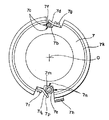
上記第2群レンズ保持枠7には、図4に示されるように、一方で棒状の案内部材であるサブロッド7fを直接固定支持し、他方でスリーブ7pを固定支持するために、外周部に2つのコの字形切欠き部7b,7mがレンズ枠光軸に対して対向して設けられている。なお、上記スリーブ7pは、後述するように棒状の案内部材であるメインロッド7eを摺動自在に支持する管状部材である。
【0029】
上記一方の切欠き部7bの2辺7cによって形成される面は、それぞれレンズ枠光軸と平行となるように成形あるいは機械加工等により形成せしめられる。上記切欠き部7bに、棒状の案内部材である第2群サブロッド7fの一端を当接させ、くの字状の固定片7dを用いてネジ7gを介して、固定片7dの斜面により上記サブロッド7fが圧接し、固定される。したがって、上記固定片7dの斜面で上記サブロッド7fを押圧するので、上記サブロッド7fは、上記切欠き部7bの2辺7cに当接する状態となり、結果的にはレンズ枠の光軸と平行して固定されることになる。
【0030】
上記他の一方の切欠き部7mの2辺7nによって形成される面は、同様にレンズ枠光軸と平行となるように成形あるいは機械加工等により形成せしめられる。上記切欠き部7mには、管状案内部材であるスリーブ7pがネジ7rで固着されるくの字状の固定片7qを用いて、その固定片7qの斜面でスリーブ7pの外周を圧接した状態で固定される。上記固定片7qの斜面で上記スリーブ7pを押圧するので、上記スリーブ7pは、上記切欠き部7mの2辺7nに当接する状態となり、結果的にレンズ枠光軸と平行な状態で固定されることになる。なお、上記スリーブ7pには、棒状の案内部材の第1のロッド部材である第2群メインロッド7eが精密嵌合(レンズ鏡筒全体の光学的性能劣化に影響を与えない程度の隙間が極めて少ない嵌合状態)して、摺動自在に挿入される。
【0031】
なお、上記スリーブ7pに挿入される第2群メインロッド7eの前方側端部には、頭部7sが設けられ、上記スリーブ7pに当接可能となっている。したがって、第2群レンズ保持枠7が前方に繰り出されて行くとき、上記メインロッド7eの先端が上記スリーブ7pの前端面より内方に進入するのが防止される。
【0032】
なお、上記メインロッド7eに設けられる頭部7sに代えて、上記メインロッド7eにEリング溝を設け、そこにEリングを嵌め込むようにしてもよい。また、上記スリーブ7pを用いることなく第2群レンズ保持枠7にロッドガイド穴を設け、直接メインロッド7eを貫通させて摺動自在に支持ようにしてもよい。
【0033】
上記スリーブ7pに支持されるメインロッド7eの上記スリーブ7p支持側と反対側端部は、上記固定枠1の嵌合穴1bに摺動自在に挿入される。また、上記装着されたロッド7fの上記固定部反対側端部は、上記固定枠1の嵌合長穴1cに摺動自在に挿入される。従って、第2群レンズ51が装着されている第2群レンズ保持枠7は、回転することなく光軸Oに沿って進退移動が可能となる。また、上記ロッド7e,7fの中間部には、それらのロッドに摺動自在に支持案内される他のレンズ保持枠の第3群レンズ保持枠8が挿入され、固定枠1に対して回転することなく光軸Oに沿って進退移動が可能となる。
【0034】
また、本保持枠7にはその軸方向の駆動用であって、光軸方向に延出した第2群駆動板7hがネジを介して固着されている。そして、この駆動板7hの先端部にはローラ7jがピン7iを介して回転自在に取り付けられている。また、上記ローラ7jは、前述のように外側ズーム環5のカム溝5cおよび固定鏡枠2の直進溝2cに嵌入される。従って、外側ズーム環5の回動および軸方向移動に伴って、上記駆動板7hを介して第2群レンズ保持枠7が光軸O方向に移動し、第2群レンズ51も同様に移動せしめられる。なお、上記駆動板7hは、その配置上、第1群枠6に設けられている凹部6eの空間部分に位置せしめられる。
【0035】
第3群レンズ保持枠8は、第3群レンズ52を保持するものであって、第2群レンズ枠7上の光軸に対して対の位置において、第2群レンズ枠7にスリーブ7pを介して自身が単体で摺動自在に挿入された第2群メインロッド7eと、第2群レンズ枠7に固着されているサブロッド7fとによって光軸方向に摺動自在に支持される。即ち、上記メインロッド7eは、第3群レンズ保持枠8の切欠部8cに嵌入され、一方、サブロッド7fは、図6のロッド装着状態を示す縦断面図に示されるように上記ロッドが嵌合するスリーブ8aを介して上記保持枠8を支持する。上記スリーブ8aは、接着剤Hにより上記保持枠8に固着されるが、スリーブ自体の外径は上記保持枠8の取付穴8bに対して遊嵌する寸法を有している。
【0036】
上記接着を行うには、先ず、それぞれ光軸と同心状に形成される第2群レンズ保持枠7の凸状嵌合部7kと第3群レンズ保持枠8の凹状嵌合部8dとを嵌合せしめ、そのとき、上記ロッド7eは切欠8cに、また、ロッド8fにはスリーブ8aを嵌合した状態で上記取付穴8bに挿入される。そして、スリーブ8aと穴8bの隙間に接着剤Hを流入させ接着を行う。
【0037】
上述のようにして第3群レンズ保持枠8、更に、第3群レンズ52は、正しく光軸中心にして同心的に取付けられ、回転せず光軸方向に平行に、しかもガタなく進退摺動できる状態となる。なお、上記第3群レンズ保持枠8と第2群レンズ保持枠7との間のロッド7fには両枠のガタ取りのための圧縮バネ18が挿入されているものとする。
【0038】
また、本第3群レンズ保持枠8には、後述する第4群レンズ保持枠9を光軸O方向に摺動自在に支持するための二本の第3群ロッド8h,サブロッド8kが取付けられている。上記サブロッド 8kは第3群レンズ保持枠8に光軸Oに平行状態で植設固定されている。その植設される穴8rは機械加工あるいは成形等で穴径,平行度等精度よく穴明けがなされている。そして該穴8rにロッド8kを圧入して植設する。なお、上記サブロッド8kとロッド8hとは、光軸Oに対して略対向して配設されるものとする(図5)。
【0039】
一方、ロッド8hは、図6に示されるように第3群レンズ保持枠8とその枠に設けられた腕8eに支持されるが、その取付穴8g,8fはロッド8hと遊嵌する状態とし、その固定は接着によって行われる。なお、その接着に先立って、第4群レンズ保持枠9に遊嵌するスリーブ9cを接着固定する。即ち、該保持枠9の摺動腕部9aに設けられた貫通穴9bに遊嵌するスリーブ9cを挿入し、機械的治具を用いて、該枠9の光軸に対してスリーブ9の内径が平行になるように保持する。その状態で接着剤Hによりスリーブ9cを穴9bに固着せしめる。そして、ロッド8hを上記スリーブ9cに嵌入して貫通し、更に、上記腕8eの遊嵌穴である穴8fと穴8gに挿入する。なお、ロッド8hには、接着以前の位置ずれ防止用のE型止め輪8mがその端部に取付けられている。
【0040】
続いて、光軸に同心的に設けられる第4群レンズ保持枠9の凸状嵌合部9gを、同様に光軸に同心的に設けられる第2群レンズ保持枠8の凹状嵌合部8pに嵌合せしめ、同時に、サブロッド8kを上記保持枠9の切欠き9dに嵌入せしめる。このようにして上記保持枠8,9の光軸を一致させ、更に、ロッド8hの方向とを一致させて、ロッド8hと保持枠8の穴8g,8fとを接着剤Hによって接着し固着せしめる。上記保持枠8,9に保持される第3,4群レンズ52,53は、光軸Oに同心的に取付けられ、しかも平行に移動させることができる。
【0041】
この第3群レンズ保持枠8のピン取付部8sには、内側ズーム環4に設けられるカム溝4aに嵌入される摺動ピン8jがネジ8iによって固着されているので、該ズーム環4の回動により、上記保持枠8が光軸O方向に進退移動せしめられる。 また、上記第3群レンズ保持枠8の被写体側の面には絞りユニット15が装着されている。そして、前記固定枠1に枢着されているチャージレバー25により、被チャージレバー15aを介して絞りユニット15の絞り操作が行われる。
【0042】
なお、被チャージレバー15aは光軸方向に長い部材となっているので上記保持枠8が光軸方向に移動してもチャージレバー25との係合は外れない。また、この絞りユニット15には絞り調定用にフォトインタラプタと電磁石装置を内蔵しているためカメラ側と電気的接続をしなければならない。そのため、このユニット15には絞り接続用フレキシブル基板15bが具備されている。
【0043】
上記第4群レンズ保持枠9は、第4群レンズ53を保持するものであって、上述したように第3群レンズ保持枠8の二本のロッド8h,8kによって光軸方向に摺動自在に支持されている。なお、ロッド8hはスリーブ9cを介して支持する。そして、この第4群レンズ保持枠9の摺動腕部9aには、内側ズーム環4に設けられるカム溝4bに嵌入される摺動ピン9fがネジ9eによって固着されているので、該ズーム環4の回動により、上記保持枠9が光軸O方向に進退移動せしめられる。
【0044】
第5群レンズ保持枠10は、第5群レンズ54を保持するものであって、その取付けは、まず、その外周10aを固定枠の嵌合穴1aと嵌合させて該レンズ光軸と光軸Oを一致させる。そして、光軸方向位置決めのため保持枠10の固定部10bをネジなどによって固定枠1に取付けるものとする。
【0045】
ズームエンコーダ部は、外側ズーム環5あるいは内側ズーム環4の光軸回りの回転角を検出するものであって、図7にも示されるように、接片台13と、その接片台13に固定され、エンコーダ基板14の導通パターン上を摺動する接片13dと、エンコーダ基板14と、該基板14を保護する金属板14aとで構成されている。
【0046】
上記接片台13は、両側面への突起13cと、両側面において接片13d方向へのわずかの高さの縁部突起13aとを有している。そして、外側ズーム環5の段部5kを有する段付角穴5f部に挿入されるが、角穴5fの段部5kに接片台13の縁部13bの裏面を当接させて装着する。
【0047】
なお、その角穴 5fは、ズーム環5の回転方向の嵌合面5eが、接片台13の縁部13bと隙間なく嵌合する寸法を有し、また、軸方向の長さは接片台13の縁部突起13aの幅寸法に、ズーム環5の軸方向の最大移動量を加えた寸法より大とする。
【0048】
角穴5f部に対応した上方に固定鏡枠2の長穴2dが位置せしめられるが、その長穴2dの回転方向の幅は、上記接片台13の周方向の移動に対して外側ズーム環5の回転駆動を許容する幅とし、一方、嵌合幅部2eである軸方向の幅は、上記接片台13の縁部突起13aあるいは両側面が摺動可能な嵌合寸法とする。
従って、接片台13は外側ズーム環5の軸方向移動全域において、その回動角に応じて長穴2d上を接片台13が移動できることになる。そして、上記長穴2dに沿って配設されるエンコーダ基板14上を接片13dが摺接して回転方向に移動するので、上記ズーム環5のズーミングの回動角を検出することができる。なお、上記エンコーダ部において接片台13は上記突起13cが長穴2dの幅部2eの縁で押えられた状態となっているため、接片台13が角穴5fから外れにくい構造となっている。
【0049】
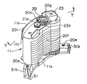
上記フォーカス駆動ユニット11について、図8〜12によって説明する。なお、図8は、上記ユニット11の外観の斜視図であって、図9は、その裏側から見た斜視図である。また、図10は、上記図8のY−Y断面を示す図である。
【0050】
上記ユニット11は、ユニットケース20と、フォーカス駆動用モータ21と、モータ出力軸21aに固着する出力歯車であるモータ出力ギヤー21bと、減速歯車列を構成するものであって、上記ギヤー21bと噛合するギヤー,太陽ギヤー,遊星ギヤーと、ユニット出力ギヤー11aと、ユニットケース止め板31と、駆動ユニット回転検出部と、更に、上記モータ21,PI23への電気接続用フレキシブルプリント基板11sとによって構成されている。
【0051】
本ユニット11は、前述したように固定枠1の円筒部1eの一部を切欠いた部分の取付面1hに取付けられる関係から、上記モータ21や減速歯車列、また、そのケース 20あるいはケース止め板31等が上記円筒部 1eの曲率に沿って配設されるものとする(図11)。
【0052】
上記回転検出部は、スリット板22とフォトインタラプタであるPI23とで構成される。そして、PI23は潤滑性のあるスライド板23aを介してユニットケース20にネジにより固着される。そして、PI23にその回転によって入力信号を与えるスリット板22は、モータ出力ギヤー21bに噛合するギヤー22aと一体的に形成され、ケース20の軸部20aに回転自在に嵌入されている。そして、ギヤー22aの軸方向の抜け止めとして上記スライド板23が作用する。
【0053】
モータ出力ギヤー21bからユニット出力ギヤー11a間の減速歯車列による動力伝達経路は、まず、モータ出力回転は、ギヤー21bに噛合するギヤー22aを介して、太陽ギヤー部24bを有するギヤー24に伝達される。そして、上記太陽ギヤー部24bの回転は、それと噛合する3つの遊星ギヤー25に伝達される。その遊星ギヤー25は、太陽ギヤー28の支持体に一体に設けられている軸部に軸方向の抜け止めが施されて軸支されている。そして、ケース20の内壁に設けられた内歯ギヤー20dと噛合している。従って、遊星ギヤー25は上記太陽ギヤー部24bの回転により自転および公転を行い、その自転により上記太陽ギヤー28が回転する。以下、その回転は、太陽ギヤー28と噛合する遊星ギヤー26とそのギヤーによって回転せしめられる太陽ギヤー29へ、更に、その太陽ギヤー29と噛合する遊星ギヤー27とそのギヤーによって回転せしめられるギヤー30へ伝達され、更に、ギヤー30は最終段であるユニット出力ギヤー11aと噛合しており、該出力ギヤー11aより減速された回転出力が得られることになる。
【0054】
なお、上記ギヤー24,ギヤー30および出力ギヤー11aは、それぞれユニットケース20と一体的に形成される軸部20b,20c,20dに軸支される。そして、太陽ギヤー28,29に対しては支持軸部を用いることなく、それぞれの3つの遊星ギヤー26または27の噛合により軸心位置に保持される。また、軸方向は、各々の端面を突合わせることによって保持されて回転する。上記ギヤー30および11aをケース20内に位置決めして保持せしめるためのユニットケース止め板31が装着される。そのケース止め板31のケースへの装着は二つの係止爪31bをケース20の取付穴20eの座の部分に弾性を利用して係合せしめて装着する。
【0055】
本ユニット11の鏡筒への取付は第1,9図に示されるようにケース止め板31側を固定枠1の取付面1hに当接させ、その位置出しダボ31aを対応する固定枠1の穴に挿入して取付ネジ部20eにネジを螺着して本ユニット11を鏡筒へ固定する。そして、固定枠1に回動自在に支持される被駆動部材であるフォーカスリング3の内歯ギヤー3eと上記ユニット出力ギヤー11aを噛合せしめ、フォーカス駆動可能状態とする。そして、モータ21のモータ出力ギヤー21bが固着された出力軸21aは、光軸方向に対して平行なM方向に延出しており、ギヤー21bに噛合する上記一連の減速歯車列の伝達経路は上記M方向とは逆のN方向に伝達される。そして、取付面側に位置するユニット出力ギヤー11aより回転出力が取出されることになる。
【0056】
上記電気接続用プリント基板11sは、図8,9に示されるように、PI23に接続された基板部11sがケース20と一体であるガイド片20g,20h,20iに掛けられて配設される。なお、基板11sの先端のL字形部分11tはガイド片20iからの外れ止め用である(図8)。
【0057】
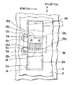
図12は図11のX−X断面図であって、ユニット11の装着状態の縦断面を示すものであるが、光路側に面するユニットケース20の曲率の内径側には小ピッチの三角溝断面の遮光面20fを有し、光束Lより外側の不要光を遮光している。また、プリント基板11sはS字状に折り曲げられて固定枠1の後面側に導かれるものとする。
【0058】
次に、以上のように構成された本実施形態のズームレンズ鏡筒のズーミングとフォーカシングおよび沈胴動作について説明する。なお、以下の説明において、回転方向は被写体側から見た回転方向によって示す。
【0059】
図3は、上記鏡筒の鏡枠沈胴状態を示しており、第1群枠6と第2群レンズ保持枠7が沈胴して、第2群メインロッド7eそれ自身単体がスリーブ7pに対して摺動して第2群レンズ保持枠7との相対位置、すなわち、スリーブ7pとの相対位置を変更し、上記メインロッド7eの先端の頭部7s側がスリーブ7pの先端面から突出し、第1群レンズ50の切り欠き部50a内に位置した状態になっている。また、上記メインロッド7eは、固定枠1の嵌合穴1bを摺動して移動するが、メインロッド7eの後端面がスペーサ40に当接して固定枠1より後方へ突出することなく、この鏡筒内部に収まっている。
【0060】
上記沈胴状態からの長焦点側へのズーミング動作を説明する。
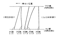
図13は、各レンズ群のワイド端からテレ端間の繰出し位置を示し、システムコントローラ(図示せず)からのズーム指示に基づいてズーム駆動ユニット12により、上記繰出し位置まで第1群〜第4群レンズを移動させる。即ち、上記駆動ユニット12の出力ギヤー12aを介して内側ズーム環4を時計回りに回動させる。その回動に伴ない摺動ピン8j,9fがカム溝4a,4bのうち沈胴領域の溝4g,4hからズーム領域の溝4i,4j部に位置するようになる(図14)。そして、上記各ピンが固着されている第3,4群レンズ枠8,9が移動し、第3,4群レンズ52,53が各ズーム位置に繰出される。一方、外側ズーム環5も内側ズーム環4に支持されるローラ4fを介して同方向に回動する。その回動によりローラ6b,7jがカム溝5c,5dのうち沈胴領域の溝部5j,5gからズーム領域の溝部5i,5hに位置せしめられる(図15(A))。同時に、上記ローラ6b,7jは固定鏡枠2の直進溝2b,2cにも嵌入しているので直進して被写体方向に移動せしめられる。なお、上記直進溝2cにおいては、沈胴領域の溝2iからズーム領域の直進溝2hに移行する。
【0061】
なお、上記沈胴状態からワイド端からテレ端へのズーミング状態において、メインロッド7eは、頭部7sがスリーブ7pの前端面に当接するまでは、スリーブ7pと固定枠1の嵌合穴1b内でフローティング状態で支持されているが、上記頭部7sがスリーブ7pの前端面に当接後は、スリーブ7p,第2レンズ保持枠7と共に繰り出し方向に移動する。
【0062】
更に、ズーム駆動時には位置不動である摺動ピン3dが外側ズーム環5のフォーカスカム溝5bに嵌入しているので、このカムの作用により外側ズーム環5自体が被写体側方向にピント補正量だけ移動する。従って、上記ローラ6b,7jが直接あるいは間接的に固着されている第1群枠6あるいは第2群レンズ保持枠7のズーミングによる移動量は、外側ズーム環5のカム溝5c,5dによって駆動される移動量と上記フォーカスカム溝5bによって駆動されるピント補正量とが加算された量の移動となる。
【0063】
なお、上記ズーム移動量の説明は長焦点側へのズーム駆動の場合を示したが、短焦点側へのズーム駆動は、内側ズーム環を反時計方向に駆動して行うことができ、その場合の動作を上記のズーム駆動と逆方向の動作となる。
【0064】
上記ズーム駆動に伴うズーム状態の検出は外側ズーム環5の回動をズームエンコーダ部で検出するが、その動作を第1,6図によって説明すると、このエンコーダは、固定鏡枠2に取付けられたエンコーダ基板14上の導通パターンを接片台13に支持された接片13dを摺接させてズーム位置に関するコード化信号を取り出すものである。
【0065】
そして、上記接片台13は、前述したように外側ズーム環5の角穴5fに円周方向のみ嵌合状態で挿入され、更に軸方向は固定鏡枠2の長穴2dの幅部2eに嵌合しているので、ズーム環5の回転に伴って接片13dは導通パターン上を摺動する。また、ズーム環5は軸方向にも移動するものであるが、その場合、上記角穴5fの軸方向の穴幅が接片台13より大であるため、接片台13は、その縁部突起13aが固定鏡枠2の長穴2dの幅部2eに案内され、接片13dがエンコーダ基板 14上を摺接してズーム位置検出信号を出力することができる。
【0066】
次に、フォーカシング動作について、被写体の∞距離(無限遠距離)に対応する状態から所定の被写体距離にフォーカシングする場合の動作について説明する。システムコントローラからの合焦指示に基づいて前記フォーカス駆動ユニット11を駆動しユニット出力ギヤー11aを介してフォーカスリング3を反時計回りに回転させる。その回転に伴い、外側ズーム環5のフォーカスカム溝5bをフォーカスリング3の摺動ピン3dが摺動するので上記ズーム環5が被写体側へ移動する。この場合、内側ズーム環4は静止状態であるので、外側ズーム環5は直進移動する。そして、ローラ6b,7jを介して第1群枠6あるいは第2群レンズ保持枠7を移動し、合焦レンズ群である第1群レンズ50,第2群レンズ51を被写体方向に繰出す。
【0067】
なお、被写体の近距離から遠距離への合焦動作は、フォーカスリング3の駆動を上記とは逆の方向に駆動せしめて動作させることになる。
【0068】
次に、本実施形態のズームレンズ鏡筒における撮影終了時の鏡枠沈胴動作について、図1,2、また、図15(A),(B)によって説明する。
まず、フォーカス駆動ユニット11を駆動し、フォーカスリング3を時計回りに回動させて、第1,2群レンズを無限遠合焦位置までカメラ本体側に後退させる。
【0069】
続いて、ズーム駆動ユニット12を駆動し、内側ズーム環4を反時計回りに回動させるが、その回転角はズーミング短焦点状態の位相より更に反時計方向に回動した鏡枠沈胴位相まで回動させる。その結果、内側ズーム環4のカム溝4a,4bに嵌入している摺動ピン8j,9fは沈胴領域であるカム溝4g,4hに位置するようになる。
【0070】
同時に、外側ズーム環5も、上記ズーム環4と同じ回転角だけ回動する。そして、図15(B)に示されるようにローラ6b,7jがズーム環5のカム溝5c,5dの沈胴領域のカム溝5g,5jに位置せしめられる。従って、第1群枠6,第2群レンズ保持枠7が∞距離対応の位置よりも更にカメラ本体側へ引き込まれた沈胴位置まで後退せしめられる。なお、上記のように第1群枠6が沈胴位置まで後退すると第2群レンズ保持枠7は通常のズーム域から外れるような位置に移動しなければ第1群レンズ保持枠6cや第1群レンズ50等との干渉あるいは、詰まり状態が生じる。そこで、上記沈胴領域の直進溝2i,カム溝5gを、そこに嵌入されるローラ7jに対して遊嵌形状とし、上記の干渉の発生を避け、沈胴を確実に行えるようになっている。
【0071】
従来のレンズ鏡筒においては、枠部材を摺動自在に支持するためのロッド部材はその端部が一方の枠部材に固着されて支持されていた。しかし、本実施形態のズームレンズ鏡筒においては、第2群メインロッド7eの両端部が第2群レンズ保持枠7および固定枠1の双方に対して摺動自在に取り付けられている。したがって、レンズ鏡筒の沈胴状態で上記第2群レンズ保持枠7が固定枠1に対して極接近した場合、上記メインロッド7eが第2群レンズ保持枠7,固定枠1に対して軸方向に位置規制されていないことから上記メインロッド7eが固定枠1の後端面より突出する寸法分だけ前方に移動させることができるので、固定枠1の後端面より上記メインロッド7eを突出させずにレンズ鏡筒を沈胴状態とすることができる。したがって、レンズ鏡筒が装着されるカメラ本体内の配置に制限を与えることがなく、レンズ鏡筒自体の沈胴状態での全長も短くすることが可能となる。
【0072】
【発明の効果】
上述したように本発明によれば、レンズ鏡筒が装着されるカメラ内の配置に大きな規制を与えることなく、レンズ鏡筒自体の長さも短くすることができ、しかも、構造も簡単であるレンズ鏡筒を提供することができる。
【図面の簡単な説明】
【図1】本発明の一実施形態を示すズームレンズ鏡筒の分解斜視図の一部である。
【図2】上記図1の一実施形態を示すズームレンズ鏡筒の分解斜視図の他の一部である。
【図3】上記図1の一実施形態を示すズームレンズ鏡筒の鏡枠沈胴状態の縦断面図である。
【図4】上記図1のA矢視図である。
【図5】上記図1のB−B断面図である。
【図6】上記図1の一実施形態のズームレンズ鏡筒の各レンズ保持枠のロッド装着状態を示す縦断面図である。
【図7】上記図1の一実施形態のズームレンズ鏡筒のズームエンコーダ部の展開図である。
【図8】上記図1の一実施形態のズームレンズ鏡筒に装着されるフォーカス駆動ユニットの斜視図である。
【図9】上記図1のズームレンズ鏡筒に装着されるフォーカス駆動ユニットを図8の裏面側から見た斜視図である。
【図10】上記図8のY−Y断面図である。
【図11】上記図1の一実施形態のズームレンズ鏡筒のフォーカス駆動ユニットの固定枠への装着状態を示す図である。
【図12】上記図11のX−X断面図、
【図13】上記図1の一実施形態のズームレンズ鏡筒のズーム駆動における各レンズ群の繰出し位置を示す図である。
【図14】上記図1の一実施形態のズームレンズ鏡筒の内側ズーム環のカム溝の展開図である。
【図15】上記図1の一実施形態のズームレンズ鏡筒の内,外側ズーム環の展開図であって、図15(A)は、ズーム動作時の展開図であり、図15(B)は、鏡枠沈胴時の展開図である。
【符号の説明】
1 ……固定枠(第2の枠部材)
7 ……第2群レンズ保持枠
(枠部材,第1の枠部材)
7e……第2群メインロッド
(ロッド,ロッド部材)[0001]
BACKGROUND OF THE INVENTION
The present invention relates to a structure of a lens barrel having a moving frame member.
[0002]
[Prior art]
Conventionally, a lens barrel proposed as a lens barrel having a moving frame member has a fixed frame and a movable lens holding frame, and the movable frame is advanced and retracted. Zooming or focusing is performed. Two rods, a main rod as a guide member and a sub rod for rotation prevention, are fixed to a second group lens holding frame which is one of the movable frames. The rod is slidably supported on the fixed frame. The third group lens holding frame is supported by the rod between the fixed frame and the second group lens holding frame. Therefore, the second group lens holding frame and the third group lens holding frame are supported so as to be able to advance and retreat in a state where rotation is restricted with respect to the fixed frame.
[0003]
[Problems to be solved by the invention]
However, in the lens barrel disclosed in Japanese Patent Laid-Open No. 4-52628, when the second group lens holding frame is retracted to the retracted position and the space between the fixed frame is closer than the wide position, The main rod protrudes outside the lens barrel behind the fixed frame. Therefore, it is necessary to provide a space in the camera body to escape the protruding main rod when the camera body side and the lens barrel are assembled and connected, and the arrangement in the camera body is limited. . However, if the protrusion of the main rod toward the camera body is eliminated, the entire length of the lens barrel must be increased by the amount of protrusion.
[0004]
The present invention has been made to solve the above-described problems, and the length of the lens barrel itself can be shortened without giving large restrictions to the arrangement in the camera, and the structure is simple. An object is to provide a lens barrel.
[0005]
[Means for Solving the Problems]
The lens barrel of the present invention is a lens barrel that performs a drawing action or a drawing action in the optical axis direction. Forward of the optical axis The above feeding action or To the rear of the optical axis In the inside of the lens barrel, the first frame member that can move in the optical axis direction in conjunction with the retraction action, The first frame member abuts on one end in the optical axis direction in conjunction with the feeding action and moves along with the movement of the first frame member in the optical axis direction. Projecting in the optical axis direction from the first frame member and the first frame member; Slidable The first frame member A rod member that supports and guides itself and is movable in the direction of the optical axis, and the rod member The other end of A second frame member slidably supported in the optical axis direction; An escape portion provided forward in the optical axis direction in the lens barrel for accommodating the protruding one end of the rod member in the completion state of the retraction; Have
[0008]
DETAILED DESCRIPTION OF THE INVENTION
Hereinafter, embodiments of the present invention will be described with reference to the drawings.
1 and 2 are exploded perspective views of a zoom lens barrel showing an embodiment of the present invention, respectively. FIG. 3 is a longitudinal sectional view of the zoom lens barrel in a retracted state.
[0009]
The zoom lens barrel enables zooming, focusing, and collapsing operations. The main components of the zoom lens barrel are a
[0010]
The
[0011]
The
[0012]
The
[0013]
The
[0014]
As shown in the developed view of FIG. 15 (A), the
[0015]
The
[0016]
Further, a sliding
[0017]
The
[0018]
The
[0019]
The
[0020]
Further, since the
[0021]
Further, the
[0022]
The
[0023]
The
[0024]
The
[0025]
A concave portion 6e that forms a thin portion along the axial direction is provided on the inner periphery of the
[0026]
The
[0027]
The second group
[0028]
As shown in FIG. 4, the second group
[0029]
The surface formed by the two
[0030]
Similarly, the surface formed by the two sides 7n of the
[0031]
A
[0032]
Instead of the
[0033]
The end of the
[0034]
Further, a second
[0035]
The third group
[0036]
In order to perform the above bonding, first, the convex
[0037]
As described above, the third lens
[0038]
The third group
[0039]
On the other hand, the
[0040]
Subsequently, the convex
[0041]
Since the
[0042]
Since the charged lever 15a is a member that is long in the optical axis direction, the engagement with the
[0043]
The fourth group
[0044]
The fifth group
[0045]
The zoom encoder unit detects the rotation angle of the
[0046]
The
[0047]
In addition, the square hole 5f has a dimension that the
[0048]
The long hole 2d of the fixed
Accordingly, the
[0049]
The
[0050]
The
[0051]
As described above, the
[0052]
The rotation detection unit includes a
[0053]
In the power transmission path by the reduction gear train between the
[0054]
The
[0055]
As shown in FIGS. 1 and 9, the
[0056]
As shown in FIGS. 8 and 9, the printed
[0057]
FIG. 12 is a cross-sectional view taken along the line XX of FIG. 11 and shows a vertical cross section of the
[0058]
Next, zooming, focusing, and collapsing operations of the zoom lens barrel of the present embodiment configured as described above will be described. In the following description, the rotation direction is indicated by the rotation direction viewed from the subject side.
[0059]
FIG. 3 shows a lens barrel retracted state of the lens barrel, in which the
[0060]
A zooming operation from the retracted state toward the long focal point will be described.
FIG. 13 shows the extended position from the wide end to the telephoto end of each lens group. The first to fourth groups are moved from the first group to the fourth position by the zoom drive unit 12 based on a zoom instruction from a system controller (not shown). Move the group lens. That is, the
[0061]
In the zooming state from the retracted state to the wide end to the tele end, the
[0062]
Further, since the sliding
[0063]
Although the above description of the zoom movement amount has shown the case of zoom driving to the long focal side, the zoom driving to the short focal side can be performed by driving the inner zoom ring counterclockwise. This operation is in the opposite direction to the zoom drive described above.
[0064]
The zoom state associated with the zoom drive is detected by the zoom encoder unit when the
[0065]
As described above, the contact table 13 is inserted into the square hole 5f of the
[0066]
Next, with regard to the focusing operation, an operation in the case of focusing from a state corresponding to the infinity distance (infinity distance) of the subject to a predetermined subject distance will be described. The
[0067]
Note that the focusing operation from a short distance to a long distance of the subject is performed by driving the
[0068]
Next, the lens barrel retracting operation at the end of photographing in the zoom lens barrel of the present embodiment will be described with reference to FIGS. 1 and 2 and FIGS.
First, the
[0069]
Subsequently, the zoom drive unit 12 is driven to rotate the
[0070]
At the same time, the
[0071]
In the conventional lens barrel, the rod member for slidably supporting the frame member is supported by being fixed to one frame member at its end. However, in the zoom lens barrel of the present embodiment, both end portions of the second group
[0072]
【The invention's effect】
As described above, according to the present invention, the length of the lens barrel itself can be shortened without greatly restricting the arrangement in the camera to which the lens barrel is mounted, and the lens has a simple structure. A lens barrel can be provided.
[Brief description of the drawings]
FIG. 1 is a part of an exploded perspective view of a zoom lens barrel showing an embodiment of the present invention.
2 is another part of an exploded perspective view of the zoom lens barrel showing the embodiment of FIG. 1; FIG.
FIG. 3 is a longitudinal sectional view of a zoom lens barrel in a retracted state of the lens barrel showing one embodiment of FIG. 1;
4 is a view taken in the direction of arrow A in FIG.
5 is a cross-sectional view taken along the line BB in FIG.
6 is a longitudinal sectional view showing a rod mounting state of each lens holding frame of the zoom lens barrel according to the embodiment of FIG. 1; FIG.
7 is a development view of a zoom encoder portion of the zoom lens barrel of the embodiment of FIG. 1; FIG.
8 is a perspective view of a focus drive unit mounted on the zoom lens barrel of the embodiment of FIG.
9 is a perspective view of the focus drive unit mounted on the zoom lens barrel of FIG. 1 as seen from the back side of FIG. 8;
10 is a YY cross-sectional view of FIG.
11 is a diagram showing a state in which the zoom lens barrel according to the embodiment of FIG. 1 is mounted on a fixed frame of a focus drive unit. FIG.
12 is a sectional view taken along line XX in FIG.
FIG. 13 is a diagram showing a feeding position of each lens group in zoom driving of the zoom lens barrel of the embodiment of FIG. 1;
14 is a development view of the cam groove of the inner zoom ring of the zoom lens barrel of the embodiment of FIG. 1; FIG.
15 is a development view of the inner and outer zoom rings of the zoom lens barrel according to the embodiment of FIG. 1. FIG. 15 (A) is a development view during a zoom operation, and FIG. 15 (B). FIG. 4 is a development view when the lens barrel is retracted.
[Explanation of symbols]
1 ...... Fixed frame (second frame member)
7 ...... Second lens group holding frame
(Frame member, first frame member)
7e …… 2nd group main rod
(Rod, rod member)
Claims (1)
上記レンズ鏡筒の内部において、光軸前方への上記繰り出し作用または光軸後方への繰り込み作用に連動して光軸方向に移動可能な第1の枠部材と、
上記レンズ鏡筒の内部において、上記繰り出し作用に連動して一端に上記第1の枠部材が光軸方向に当接し上記第1の枠部材の光軸方向の移動と伴に移動し、上記繰り込み作用に連動して該一端が上記第1の枠部材より光軸方向に突出し上記第1の枠部材と摺動可能に上記第1の枠部材を案内支持すると共に自身が単体で光軸方向に移動可能なロッド部材と、
上記ロッド部材の他端を光軸方向に摺動可能に支持する第2の枠部材と、
上記繰り込みの完了状態において上記ロッド部材の上記突出した上記一端を納める上記レンズ鏡筒内の光軸方向前方に設けられた逃げ部と、
を有することを特徴とするレンズ鏡筒。In a lens barrel that performs a drawing action or a drawing action in the optical axis direction,
A first frame member that is movable in the direction of the optical axis in conjunction with the extension action forward of the optical axis or the extension action backward of the optical axis inside the lens barrel;
In the interior of the lens barrel, the first frame member comes into contact with one end in the optical axis direction in conjunction with the extension operation, and moves together with the movement of the first frame member in the optical axis direction, and the retraction In conjunction with the action, the one end protrudes from the first frame member in the optical axis direction, and guides and supports the first frame member so as to be slidable with the first frame member, and itself is alone in the optical axis direction. A movable rod member;
A second frame member that slidably supports the other end of the rod member in the optical axis direction;
An escape portion provided forward in the optical axis direction in the lens barrel for accommodating the protruding one end of the rod member in the completion state of the retraction;
A lens barrel comprising:
Priority Applications (2)
| Application Number | Priority Date | Filing Date | Title |
|---|---|---|---|
| JP2002136332A JP4339552B2 (en) | 2001-08-20 | 2002-05-10 | Lens barrel |
| US10/197,154 US6778335B2 (en) | 2001-08-20 | 2002-07-17 | Lens barrel whose length can be reduced |
Applications Claiming Priority (3)
| Application Number | Priority Date | Filing Date | Title |
|---|---|---|---|
| JP2001-249390 | 2001-08-20 | ||
| JP2001249390 | 2001-08-20 | ||
| JP2002136332A JP4339552B2 (en) | 2001-08-20 | 2002-05-10 | Lens barrel |
Related Child Applications (1)
| Application Number | Title | Priority Date | Filing Date |
|---|---|---|---|
| JP2007055305A Division JP2007206710A (en) | 2001-08-20 | 2007-03-06 | Lens barrel |
Publications (2)
| Publication Number | Publication Date |
|---|---|
| JP2003140019A JP2003140019A (en) | 2003-05-14 |
| JP4339552B2 true JP4339552B2 (en) | 2009-10-07 |
Family
ID=26620676
Family Applications (1)
| Application Number | Title | Priority Date | Filing Date |
|---|---|---|---|
| JP2002136332A Expired - Fee Related JP4339552B2 (en) | 2001-08-20 | 2002-05-10 | Lens barrel |
Country Status (2)
| Country | Link |
|---|---|
| US (1) | US6778335B2 (en) |
| JP (1) | JP4339552B2 (en) |
Families Citing this family (18)
| Publication number | Priority date | Publication date | Assignee | Title |
|---|---|---|---|---|
| JP4575114B2 (en) * | 2003-12-24 | 2010-11-04 | オリンパス株式会社 | Zoom lens barrel |
| JP2006030360A (en) * | 2004-07-13 | 2006-02-02 | Konica Minolta Photo Imaging Inc | Lens unit and camera incorporating this unit |
| JP2007114530A (en) * | 2005-10-20 | 2007-05-10 | Sony Corp | Lens barrel |
| US7821569B2 (en) * | 2006-02-10 | 2010-10-26 | Lumos Technology Co., Ltd. | Converter lens attachment with built-in light source for compact digital camera |
| TW200809295A (en) * | 2006-08-03 | 2008-02-16 | Asia Optical Co Inc | Optical lens capable of preventing light leakage |
| JP4876774B2 (en) * | 2006-08-22 | 2012-02-15 | コニカミノルタオプト株式会社 | Lens barrel and imaging device |
| JP2008102427A (en) * | 2006-10-20 | 2008-05-01 | Tamron Co Ltd | Optical apparatus and imaging apparatus |
| JP4924631B2 (en) * | 2009-02-17 | 2012-04-25 | 株式会社ニコン | Lens barrel and imaging device |
| CN102520562B (en) * | 2009-01-28 | 2014-09-10 | 奥林巴斯映像株式会社 | Image pickup apparatus and camera shake correcting apparatus applied to image pickup apparatus |
| JP5509620B2 (en) * | 2009-02-27 | 2014-06-04 | 株式会社ニコン | Lens barrel and imaging device |
| JP5566163B2 (en) * | 2010-03-31 | 2014-08-06 | キヤノン株式会社 | Lens barrel and imaging device |
| TW201241546A (en) * | 2011-04-11 | 2012-10-16 | Asia Optical Co Inc | Focusing mechanism with multiple precision |
| CN103076663B (en) * | 2011-10-25 | 2016-08-10 | 亚洲光学股份有限公司 | A lens that shares a single detection component for focusing and zooming and its reset method |
| TW201323964A (en) * | 2011-12-06 | 2013-06-16 | Hon Hai Prec Ind Co Ltd | Lens module |
| JP5929311B2 (en) | 2012-02-28 | 2016-06-01 | 株式会社ニコン | Lens barrel and imaging device |
| JP6508930B2 (en) | 2014-12-10 | 2019-05-08 | キヤノン株式会社 | Lens barrel and optical apparatus having the same |
| JP6403561B2 (en) * | 2014-12-10 | 2018-10-10 | キヤノン株式会社 | Lens barrel and optical apparatus having the same |
| CN121454724A (en) * | 2025-08-22 | 2026-02-03 | 深圳市中图仪器股份有限公司 | zoom system |
Family Cites Families (3)
| Publication number | Priority date | Publication date | Assignee | Title |
|---|---|---|---|---|
| JP2863605B2 (en) | 1990-06-20 | 1999-03-03 | オリンパス光学工業株式会社 | Zoom lens barrel |
| US5715481A (en) * | 1996-01-16 | 1998-02-03 | Fuji Photo Optical Co. Ltd. | Initial focusing mechanism for a variable-focus photographic camera |
| TW495641B (en) * | 2001-06-06 | 2002-07-21 | Arc Design Inc | Two zone automatic lens focusing system for digital still cameras |
-
2002
- 2002-05-10 JP JP2002136332A patent/JP4339552B2/en not_active Expired - Fee Related
- 2002-07-17 US US10/197,154 patent/US6778335B2/en not_active Expired - Fee Related
Also Published As
| Publication number | Publication date |
|---|---|
| US20030035228A1 (en) | 2003-02-20 |
| US6778335B2 (en) | 2004-08-17 |
| JP2003140019A (en) | 2003-05-14 |
Similar Documents
| Publication | Publication Date | Title |
|---|---|---|
| JP4339552B2 (en) | Lens barrel | |
| JP3240758B2 (en) | Zoom lens device and camera | |
| JPH09281375A (en) | Lens barrel | |
| JP5172376B2 (en) | Optical device shading structure | |
| JP2009192814A (en) | Lens barrel storage structure | |
| JP4455350B2 (en) | Imaging device | |
| JPH04136908A (en) | Initial focus adjusting mechanism of zoom lens | |
| JP2863605B2 (en) | Zoom lens barrel | |
| JP3342480B2 (en) | Lens barrel | |
| JP2007206710A (en) | Lens barrel | |
| JP2816243B2 (en) | Lens barrel positioning mechanism and positioning method | |
| JPH02262112A (en) | Motor-driven zooming device | |
| JP2007033961A (en) | Lens driving apparatus | |
| JP5573026B2 (en) | Lens barrel and camera | |
| JP2816242B2 (en) | Lens barrel | |
| JP3297032B2 (en) | Zoom encoder device for zoom lens | |
| JP2012053413A (en) | Lens barrel and imaging apparatus | |
| JP3990904B2 (en) | camera | |
| JP3170244B2 (en) | Lens barrel | |
| JP2959725B2 (en) | Drive mechanism | |
| JP3128129B2 (en) | Lens barrel positioning mechanism and positioning method | |
| JPH10260342A (en) | Lens barrel | |
| JP3401232B2 (en) | Lens barrel | |
| JP3903124B2 (en) | Lens drive device for optical device | |
| JP2002341225A (en) | Lens barrel |
Legal Events
| Date | Code | Title | Description |
|---|---|---|---|
| A621 | Written request for application examination |
Free format text: JAPANESE INTERMEDIATE CODE: A621 Effective date: 20050118 |
|
| A977 | Report on retrieval |
Free format text: JAPANESE INTERMEDIATE CODE: A971007 Effective date: 20060919 |
|
| A131 | Notification of reasons for refusal |
Free format text: JAPANESE INTERMEDIATE CODE: A131 Effective date: 20061010 |
|
| A521 | Written amendment |
Free format text: JAPANESE INTERMEDIATE CODE: A523 Effective date: 20061211 |
|
| A02 | Decision of refusal |
Free format text: JAPANESE INTERMEDIATE CODE: A02 Effective date: 20070206 |
|
| A521 | Written amendment |
Free format text: JAPANESE INTERMEDIATE CODE: A523 Effective date: 20090508 |
|
| A01 | Written decision to grant a patent or to grant a registration (utility model) |
Free format text: JAPANESE INTERMEDIATE CODE: A01 |
|
| A61 | First payment of annual fees (during grant procedure) |
Free format text: JAPANESE INTERMEDIATE CODE: A61 Effective date: 20090702 |
|
| FPAY | Renewal fee payment (event date is renewal date of database) |
Free format text: PAYMENT UNTIL: 20120710 Year of fee payment: 3 |
|
| FPAY | Renewal fee payment (event date is renewal date of database) |
Free format text: PAYMENT UNTIL: 20130710 Year of fee payment: 4 |
|
| S531 | Written request for registration of change of domicile |
Free format text: JAPANESE INTERMEDIATE CODE: R313531 |
|
| R350 | Written notification of registration of transfer |
Free format text: JAPANESE INTERMEDIATE CODE: R350 |
|
| LAPS | Cancellation because of no payment of annual fees |


