JP4339521B2 - System and method for receiving a modulated signal including encoded and uncoded bits using multipath demodulation - Google Patents
System and method for receiving a modulated signal including encoded and uncoded bits using multipath demodulation Download PDFInfo
- Publication number
- JP4339521B2 JP4339521B2 JP2000586057A JP2000586057A JP4339521B2 JP 4339521 B2 JP4339521 B2 JP 4339521B2 JP 2000586057 A JP2000586057 A JP 2000586057A JP 2000586057 A JP2000586057 A JP 2000586057A JP 4339521 B2 JP4339521 B2 JP 4339521B2
- Authority
- JP
- Japan
- Prior art keywords
- slot
- bit
- estimate
- decoded
- demodulation
- Prior art date
- Legal status (The legal status is an assumption and is not a legal conclusion. Google has not performed a legal analysis and makes no representation as to the accuracy of the status listed.)
- Expired - Fee Related
Links
- 238000000034 method Methods 0.000 title claims abstract description 79
- 239000000872 buffer Substances 0.000 claims description 28
- 238000001514 detection method Methods 0.000 claims description 20
- 238000004422 calculation algorithm Methods 0.000 claims description 18
- 230000007704 transition Effects 0.000 claims description 18
- 230000008569 process Effects 0.000 claims description 10
- 230000004044 response Effects 0.000 claims description 9
- 230000005540 biological transmission Effects 0.000 claims description 8
- 230000008859 change Effects 0.000 claims description 3
- 238000004891 communication Methods 0.000 description 13
- 238000010586 diagram Methods 0.000 description 13
- 230000006872 improvement Effects 0.000 description 11
- 230000006870 function Effects 0.000 description 7
- 238000005562 fading Methods 0.000 description 6
- 230000001413 cellular effect Effects 0.000 description 5
- 230000000694 effects Effects 0.000 description 5
- 238000004364 calculation method Methods 0.000 description 4
- 238000012937 correction Methods 0.000 description 4
- 239000006185 dispersion Substances 0.000 description 4
- 238000007476 Maximum Likelihood Methods 0.000 description 3
- 230000001427 coherent effect Effects 0.000 description 3
- 238000005516 engineering process Methods 0.000 description 3
- 238000007792 addition Methods 0.000 description 2
- 238000004458 analytical method Methods 0.000 description 2
- 238000004590 computer program Methods 0.000 description 2
- 230000001186 cumulative effect Effects 0.000 description 2
- 238000013461 design Methods 0.000 description 2
- 230000003993 interaction Effects 0.000 description 2
- 230000004083 survival effect Effects 0.000 description 2
- IRLPACMLTUPBCL-KQYNXXCUSA-N 5'-adenylyl sulfate Chemical compound C1=NC=2C(N)=NC=NC=2N1[C@@H]1O[C@H](COP(O)(=O)OS(O)(=O)=O)[C@@H](O)[C@H]1O IRLPACMLTUPBCL-KQYNXXCUSA-N 0.000 description 1
- 230000003044 adaptive effect Effects 0.000 description 1
- 238000013459 approach Methods 0.000 description 1
- 125000004122 cyclic group Chemical group 0.000 description 1
- 230000002950 deficient Effects 0.000 description 1
- 230000000593 degrading effect Effects 0.000 description 1
- 230000003111 delayed effect Effects 0.000 description 1
- 230000007613 environmental effect Effects 0.000 description 1
- 238000001914 filtration Methods 0.000 description 1
- 230000002452 interceptive effect Effects 0.000 description 1
- 230000000873 masking effect Effects 0.000 description 1
- 239000011159 matrix material Substances 0.000 description 1
- 238000010295 mobile communication Methods 0.000 description 1
- 238000012805 post-processing Methods 0.000 description 1
- 230000001360 synchronised effect Effects 0.000 description 1
- 230000009897 systematic effect Effects 0.000 description 1
- 238000012360 testing method Methods 0.000 description 1
- 238000012549 training Methods 0.000 description 1
Images


Classifications
-
- H—ELECTRICITY
- H04—ELECTRIC COMMUNICATION TECHNIQUE
- H04L—TRANSMISSION OF DIGITAL INFORMATION, e.g. TELEGRAPHIC COMMUNICATION
- H04L25/00—Baseband systems
- H04L25/02—Details ; arrangements for supplying electrical power along data transmission lines
- H04L25/03—Shaping networks in transmitter or receiver, e.g. adaptive shaping networks
- H04L25/03006—Arrangements for removing intersymbol interference
- H04L25/03171—Arrangements involving maximum a posteriori probability [MAP] detection
-
- H—ELECTRICITY
- H04—ELECTRIC COMMUNICATION TECHNIQUE
- H04L—TRANSMISSION OF DIGITAL INFORMATION, e.g. TELEGRAPHIC COMMUNICATION
- H04L1/00—Arrangements for detecting or preventing errors in the information received
- H04L1/004—Arrangements for detecting or preventing errors in the information received by using forward error control
- H04L1/0045—Arrangements at the receiver end
- H04L1/0047—Decoding adapted to other signal detection operation
- H04L1/005—Iterative decoding, including iteration between signal detection and decoding operation
-
- H—ELECTRICITY
- H04—ELECTRIC COMMUNICATION TECHNIQUE
- H04L—TRANSMISSION OF DIGITAL INFORMATION, e.g. TELEGRAPHIC COMMUNICATION
- H04L1/00—Arrangements for detecting or preventing errors in the information received
- H04L1/004—Arrangements for detecting or preventing errors in the information received by using forward error control
- H04L1/0056—Systems characterized by the type of code used
- H04L1/007—Unequal error protection
-
- H—ELECTRICITY
- H04—ELECTRIC COMMUNICATION TECHNIQUE
- H04L—TRANSMISSION OF DIGITAL INFORMATION, e.g. TELEGRAPHIC COMMUNICATION
- H04L25/00—Baseband systems
- H04L25/02—Details ; arrangements for supplying electrical power along data transmission lines
- H04L25/03—Shaping networks in transmitter or receiver, e.g. adaptive shaping networks
- H04L25/03006—Arrangements for removing intersymbol interference
- H04L25/03178—Arrangements involving sequence estimation techniques
- H04L25/03203—Trellis search techniques
- H04L25/03216—Trellis search techniques using the M-algorithm
-
- H—ELECTRICITY
- H04—ELECTRIC COMMUNICATION TECHNIQUE
- H04L—TRANSMISSION OF DIGITAL INFORMATION, e.g. TELEGRAPHIC COMMUNICATION
- H04L25/00—Baseband systems
- H04L25/02—Details ; arrangements for supplying electrical power along data transmission lines
- H04L25/03—Shaping networks in transmitter or receiver, e.g. adaptive shaping networks
- H04L25/03006—Arrangements for removing intersymbol interference
- H04L25/03178—Arrangements involving sequence estimation techniques
- H04L25/03248—Arrangements for operating in conjunction with other apparatus
- H04L25/03273—Arrangements for operating in conjunction with other apparatus with carrier recovery circuitry
Abstract
Description
【0001】
(発明の分野)
本発明は電気通信システムに関するものであって、更に詳細には変調された信号を受信するためのシステムおよび方法に関する。
【0002】
(発明の背景)
加入者へ音声およびデータ通信を提供するために公衆無線電話システムが広く採用されている。例えば、AMPS、ETACS、NMT−450、およびNMT−900と表記されるようなアナログ式のセルラ無線電話システムが世界中で成功裏に展開してから久しい。北米標準規格IS−54および欧州標準規格GSMに従うようなディジタル式のセルラ無線電話システムが1990年代初期からサービスを開始している。より最近では、広くPCS(パーソナル通信サービス)と呼ばれる多様な無線式ディジタル・サービスが導入されてきており、その中には、IS−136やIS−95などの標準規格に従う先進的なディジタル式セルラ・システム、DECT(ディジタル・エンハーンスト・コードレス電話)のような低電力システム、およびCDPD(セルラ・ディジタル・パケット・データ)のようなデータ通信サービスが含まれる。これらおよびその他のシステムについては、CRCプレス出版のギブソン(Gibson)著“移動通信ハンドブック(The Mobile Communications Handbook)”(1996年)に記述されている。
【0003】
セルラ無線電話システムのような無線電気通信システムは、第1のトランシーバ(例えば基地局)と第2のトランシーバ(例えば移動端末)との間に確立される複数の通信チャネルを含むのが普通である。通信チャネルは一般に、多重経路フェージングおよび干渉(雑音)のような特性を劣化させる環境効果に晒される。フェージング効果には、送信された信号(主光線)が、同時に受信機に到着する送信信号の反射と相互作用することによって生ずる平坦フェージングが含まれる。別のタイプのフェージングである時間分散は、主光線が時間的に遅延した主光線の反射と相互作用することによって生ずる。干渉効果は、所望の送信信号源以外の信号源によって信号媒体中で発生する非直交信号の相互作用によって生ずる。最尤系列推定法(MLSE)などの等化法を用いて時間分散を補償することができる。干渉は、望まない信号の受信を減らすようにアンテナ・ビームを調節することによって減らすことができる。
【0004】
フェージングは一般に電気通信システム中の復調器の特性を劣化させる主因である。移動端末の受信機は、最尤系列推定器(MLSE)復調器(あるいはイコライザ)のようなコヒーレント復調器である復調器を含むのが普通である。受信した信号を信頼性高く復調するために、復調器には付随チャネル・トラッカが設けられるのが普通である。送信された信号を受信機で取得した後で、チャネル・トラッカは、復調器と受信信号との間のコヒーレントな相関を与えるためのチャネル推定値を保持する。
【0005】
復号器から復調器へフィードバックすることによって復調と復号とを組み合わせる方法は受信機特性を改善する1つのやり方である。これはマルチパス(multi−pass)復調によって実現されよう。情報理論によれば、最適な受信機は復調と復号の操作を結合させて実行する。そのような操作の複雑さは、特にシステム中でインターリーブが行なわれる場合に顕著である。しかし、復号器から復調器へのフィードバックを行なうことによって、分離した復調および復号と結合した復調および復号との間のギャップの一部を橋渡しすることは可能である。これがマルチパス復調の背後にある概念である。
【0006】
そのようなマルチパス復調の例がデント(Dent)による米国特許第5,673,291号に述べられている。この第’291号の特許は、まず受信した信号を復調し、次にコード化シンボルを復号して、その後、復号器出力を再符号化することによって得られる情報を復調器へ供給することによって非コード化シンボルを優れた特性で再復調することについて述べている。再符号化されたシンボルは優れた特性を持つ既知のシンボルとして活用される。再符号化されたシンボルは、送信の前にデータ中に挿入された真に既知のシンボルである同期シンボルをそれが活用するのと同じように、復調器によって既知のシンボルとして活用される。この第’291号特許の方法およびシステムは一般に、送信された信号ストリーム中に配置するシンボルの順序についての受信機の知識に部分的に基づいており、また任意の既知の同期シンボルの配置に基づいている。別のやり方では、ガー(Garr)等は、復調器への軟帰還によって完全に符号化されたビット・ストリーム用マルチパス復調器を提案している。ガー(Garr)等が1988年3月、プリンストン大学での情報科学およびシステムに関する会議で発表した“GSM信号の繰り返し復号(Iterative Decoding of GSM Signals)”。更に別の提案方式が、例えば、1993年IEEE国際通信会議の会議録のページ1064−1070に発表されたベロウ(Berrou)等による“近シャノン限界誤り訂正符号化および復号:ターボ符号(1)(Near Shannon Limit Error−correcting Coding and Decoding:Turbo−codes(1))”に述べられているが、それは2つの再帰的畳み込み符号の並列連接を用いたターボ符号の使用を提案している。同様に、2つの再帰的畳み込み符号の直列連接が、1996年8月15日にイタリア国トリノ大学でのTDAプログレス・レポート42−126にベネデット(Benedetto)等が発表した“インターリーブ符号の直列連接:特性解析、設計、および繰り返し復号(Serial Concatenation of Interleaved Codes:performance Analysis, Design and Iterative Decoding)”に提案されている。
【0007】
第’291号の特許に提案されているものや、非符号化ビット・クラスを含む通信システムに関しては問題がある。現在提案されている各種の電気通信標準規格に関連するそのようなコードの例が図1Aおよび1Bに示されている。図1AはIS−136規格用に記述された一例の音声コード化システムを示す。図1BはIS−641規格用の同様なフォーマットを示す。図1Aに示すように、コード化システム10は1つのデータ・フレームとして159ビットを出力するベクトル和励起線形予測(VSELP)ボコーダを含む。これらのビットは3種類のコード化クラス、すなわちクラス1A、クラス1B、およびクラス2に分類される。クラス1Aに属する12ビットがまずCRC誤り検出コーダ14へ送られ、それらを畳み込み符号化器16へ送る前に12ビットのクラス1Aビットに対して周期的冗長検査(CRC)誤り検出符号を追加する。クラス1Bとして分類される付加的な65ビットが誤り検出コード化なしで畳み込み符号化器16へ直接送られる。最後に、クラス2に属するビットである82ビットが誤り検出または訂正符号化なしでインターリーバ18へ直接送られる。畳み込み符号化器16の出力および保護なしクラス2のビットが2スロット式インターリーバ18へ送られる。インターリーバ18は元のデータ・フレームを2つのフレームに分割して、各フレームが元の情報の半分を有するようにし、また各フレームがスロット・フォーマッタ19によって2つの隣接するスロット(すなわち、逐次的送信窓)の1つに配置されて、復調器(図示されていない)によって送信できるようにする。
【0008】
ここで図1Bを参照しながら、IS−641標準規格のコード化構造について説明しよう。コード化システム20の適応符号励起線形予測(ACELP)ボコーダ22は148ビットのデータ・フレームを供給する。このうち48ビットはクラス1Aに分類されCRC誤り検出コーダ24へ送られて、そこで誤り検出符号がビットに追加される。148ビット・データ・フレームのうちの付加的な48ビットはクラス1Bとして分類され、誤り検出コード化なしで畳み込みコーダ26へ供給される。残りの52ビットはクラス2として扱われ、コード化なしでインターリーバ28へ直接供給される。クラス1Aおよび1Bのビットは畳み込み符号化器26を通過して、次に回路27によってパンクチャされて、52個のクラス2ビットと組み合わせた時に2スロット式インターリーバ28に対して合計で260ビットを供給するようにされる。図1Aに関して上で説明したのと同じように、インターリーバ28およびスロット・フォーマッタ29は信号源22からの148ビットを、送信のために復調器へ供給される2つの分離したスロットに分割することによってインターリーブを実行する。
欧州特許出願第EP0 802 656号、国際公開第WO98/48517号および米国ピスカタウエイ、米国IEEEサービス・センター発行のIEEE通信レター(IEEE Communications Letters)1997年3月1日付け第1巻、第2号、ページ49−51に掲載されたK.R.ナラヤナン(Narayanan)等による“ターボ符号化原理を利用した新規なARQ技術(A Novel ARQ Technique Using the Turbo Coding Principle)”、XP000687091およびミラノ、AEI、IT発行の電気通信および関連技術に関する欧州紀要(European Transactions on Telecommunications and Related Technologies)1995年9月1日付け第6巻、第5号ページ507−511に掲載されたC.ドーイラード(Douillard)等による“シンボル間干渉のインタラクティブ修正:ターボ等化(Interactive Correction of Intersymbol Interference:Turbo−Equal ization)”XP002055352は通信システムにおける受信信号の復号に一般的に関連している。ドイツ国特許出願第DE195 47 018A1号は、トレーニング系列、保護されたビットおよび保護されないビットを備えた送信バーストを受信するための受信機に関連しており、保護されたビットを復号し、次に保護されないビットの受信を改善するように、判定されたチャネル減衰特性を改善するためにそれを用いるようになっている。
【0009】
これら各種の方式は進歩した信号受信を実現する可能性を秘めているものの、符号化および非符号化データを含む変調された信号用の受信機の性能を改善する必要性は引き続き存在する。更に別の要求として、そのような改善は既存の通信プロトコル標準規格と一緒に使用できなければならない。
【0010】
(発明の概要)
従って、本発明の1つの目的は、無線通信システムにおける受信誤りの問題を、符号化ビットおよび非符号化ビットを含む変調された信号を、マルチパス復調器を用いて受信するための方法およびシステムを提供することによって解決することである。
【0011】
本発明の付加的な目的は、既存の通信プロトコル標準規格と一緒に使用できるそのようなシステムおよび方法を提供することである。
【0012】
本発明の更に別の目的は、硬および軟の両出力情報を提供するMLSEタイプの復調器と一緒に有利に使用できるそのようなシステムおよび方法を提供することである。
【0013】
本発明の更に別の目的は、復調器におけるMアルゴリズムの複雑さの減少を、マルチパス復調のフィードバック情報と組み合わせることによって効率的な高性能受信機を得ることである。
【0014】
これらおよびその他の目的は、本発明に従って、1つのデータ(例えば音声)フレームから符号化および非符号化の両ビットを表すシンボルを含む変調された信号を受信するための、まず受信された1つのスロットを復調し、符号化ビットを復号する方法およびシステムを提供することによって提供される。復号されたビットは次に、受信された1スロットの第2の復調時の復調を制約するために用いられる。制約された第2復調からの符号化ビット位置は、次に符号化されて、受信されたスロットに対するビット推定値を生成する。この情報は非符号化ビットの制約された第2復調の出力と組み合わされて、符号化および非符号化の両ビットの高い信頼性を提供することが明らかにされた受信データ・フレーム推定値を提供する。
【0015】
特に、1つのデータ・フレームからの第1サブセット・ビットに対応する符号化ビットおよび同データ・フレームからの第2サブセット・ビットに対応する非符号化ビットを表すシンボルを含む逐次的に送信される複数のスロットを含む変調された信号を受信するための方法が提供される。第1スロットが受信され復調されて、符号化ビット位置および非符号化ビット位置を有する第1スロット推定値が提供される。第1スロット推定値の符号化ビット位置が復号されて、第1の復号ビット推定値が提供される。第1スロットは次に、好ましくは畳み込みによって制約付き復調されて、符号化ビット位置および非符号化ビット位置を有し、符号化ビット位置の第2スロット推定値が第1の復号ビット推定値に従って制約されている第2スロット推定値が提供される。第2スロット推定値の符号化ビット位置が復号されて第2復号ビット推定値が提供され、それは第2スロット推定値の非符号化ビット位置と組み合わされて受信データ・フレーム推定値が提供される。
【0016】
本発明の方法の別の実施の形態に従えば、第1スロット推定値を得るための復号の後で、第1復号ビット推定値中で何らかの誤りの検出が行なわれ、誤りが検出された場合には、第2復号ビット推定値を生成するために第2スロット推定値の符号化ビット位置は使用されない。誤り検出は、CRCビットのような少なくとも1つの誤り検出ビットを第1復号ビット推定値中に含め、その少なくとも1つの誤り検出ビットに基づいて第1復号ビット推定値中で誤り検出を行なうことによって提供されよう。
【0017】
本発明の実施の形態に従う制約付き復調操作は、第1スロットの符号化ビット位置の1つに対応する場所にビット推定値を有し、それが第1の復号ビット推定値の関連するものとは異なっている任意のビット経路候補を復調時に無視することを含むことができる。あるいは、第1スロットの符号化ビット位置の1つに対応する場所にビット推定値を有し、それが第1の復号ビット推定値の関連するものとは異なっている任意のビット経路候補のメトリックをバイアスしてそのビット経路候補を敬遠することができる。更に、復号器は第1復号ビット推定値の各々に対して付随する軟信頼値を出力することができ、それによってその第1スロットは、第1スロットの符号化ビット位置の1つに対応する場所にビット推定値を有し、それが第1の復号ビット推定値の関連するものとは異なっている任意のビット経路候補のメトリックを、第1復号ビット推定値の関連するものに付随する軟信頼値に基づいてバイアスすることによって、畳み込み方式で制約付き復調されよう。
【0018】
本発明の別の実施の形態では、制約付き復調の繰り返し、最近の復号工程からの復号ビット推定値を用いて再帰カウンタが上限に到達するまで制約付き復調を制約するために第2スロット推定値の符号化ビット位置を復号する操作、および最後のスロット推定値の復号ビット推定値と非符号化ビット推定値との最終的な組を組み合わせることによる受信フレーム推定値の提供によってマルチパス復調が再帰的に提供される。あるいは、再帰的操作は信頼性基準が満たされるまで継続されよう。信頼性基準は性能でよい。
【0019】
別の態様では、差動復号器を用いて第1の復調操作を行なう。あるいは、信頼性基準が満たされる場合には差動復号器が用いられ、そうでない場合は畳み込み復号器が使用されよう。本発明は、制約付き復調操作において、生き残り当り処理(per−survivor process)と一緒に用いても良い。更に、復調のパス毎に別々のバッファ・メモリを使用してもよいし、あるいは単一のバッファ・メモリをパス毎に上書きするようにしてもよい。
【0020】
別の実施の形態における本発明の利点は、送信スロットにインターリーブされたデータ送信が含まれる場合に実現されよう。第1スロットが第2スロットの前に受信されよう。第1復号ビット推定値、第1スロット推定値の非符号化ビット位置からのビット、および第2セグメント・ビットに対応する未知のビットが組み合わされて再生スロットが提供され、復調時にトレリス遷移を制限するようにこの再生スロットを用いることによって制約付き復調操作が制約されよう。あるいは、復調時のトレリス遷移の制約は、選ばれたビット経路候補のメトリックを、再生されたスロットに基づいてバイアスすることによって行なわれよう。
【0021】
本発明の別の実施の形態では、複数のトレリス・ステージを有するMアルゴリズムを用いて、第1スロットがトレリス制約付きで復調される。複数のトレリス・ステージの少なくとも1つに対する生き残り状態の数が指定されよう。また、複数のトレリス・ステージに対する生き残り状態の数は、許容できる経路のみが生き残り状態として生き残ることを許されるように指定されよう。
【0022】
本発明の別の態様では、逐次的に送信される複数のスロットを含む変調信号を受信するための方法が提供される。第1スロットが受信され復調されて、第1スロット推定値が提供される。第1スロット推定値が復号されて、第1復号ビット推定値が提供される。第1スロットは次に制約付き復調されて、第2スロット推定値が提供され、そこでは第2スロット推定値中の複数のビット位置が第1復号ビット推定値中の対応するものに等しくなるように制約される。第2スロット推定値が復号されて、受信データ・フレーム推定値が提供される。第2スロット推定値に対する制約付き復調操作およびを復号操作は、制約付き復調工程を制約するためのデータ・フレーム推定値を用いて再帰的に繰り返される。
【0023】
本発明のシステム的な態様では、1つのデータ・フレームからの第1サブセット・ビットに対応する符号化ビットおよび同データ・フレームからの第2サブセット・ビットに対応する非符号化ビットを表すシンボルを含む逐次的に送信される複数のスロットを含む変調信号を受信するための受信機が提供される。本受信機は、送信されたスロットを受信するように構成された受信機回路、および前記受信機につながれて、受信スロットから第1スロット推定値を生成するように構成された第1復調器を含む。前記復調器には第1復号器がつながれて、前記第1スロット推定値および制約スロットから第1復号ビット推定値を提供するようになっている。前記制約スロットに基づいて第2スロット推定値を生成するように構成された制約付き復調器もまた提供される。制約付き復調器につながれて、前記第2スロット推定値から第2復号ビット推定値を提供するようになった第2復号器が提供される。前記第2復号ビット推定値と前記第2スロット推定値の非符号化ビット位置とを組み合わせて受信データ・フレーム推定値を提供するための手段も含まれる。
【0024】
本発明は以上のように主として方法態様に関して説明してきたが、本発明は本発明の方法を実行するように構成されるシステムを含むシステム態様をも包含することを理解すべきである。このように、本発明は、進歩した受信機性能を提供するマルチパス復調への新規なアプローチを提供する。
【0025】
(発明の詳細な説明)
ここで本発明について、本発明の好適な実施の形態を示している添付図面を参照しながらより完全に説明する。しかし、本発明は数多くの形態で実施できるものであって、ここに提示する実施の形態に限定されると理解すべきではなく、むしろこれらの実施の形態は本開示が完全な体をなしており、本発明のスコープを当業者に完全に伝えるために提供されている。当業者には理解されるであろうが、本発明は方法として、あるいは装置として実施できる。従って、本発明はハードウエアとしての実施の形態、ソフトウエアとしての実施の形態、あるいはソフトウエアおよびハードウエアの両形態を組み合わせた実施の形態を取ることができる。
【0026】
本発明の動作は、ここに主として、ACELP形式の音声フレーム(上で図1Bに関して述べたIS−641標準規格に指定されたような)で動作し、符号化および非符号化ビットを含む移動端末に関して説明する。しかし、本発明の利点は、雑音、フェージング、およびその他のチャネル効果に晒されるチャネル上を送信される変調信号を用いるその他の通信システムで稼動する移動端末においても実現できる。
【0027】
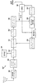
図2は本発明に従う受信機の実施の形態を示す。図2の実施の形態に示すように、受信機30は、移動端末のような装置のアンテナなどの信号源からの信号を受信およびフィルタリングする受信機フィルタ32を含む。受信機フィルタ32からの出力信号は、復調のために、イコライザ(復調器)36へ連続的なスロットを提供する同期回路34へ供給される。
【0028】
ACELPで規定されるようなインターリーブ式の通信形式に関して、イコライザ36からの出力スロット推定値は次にデインターリーバ/アンフォーマット回路38へ供給される。符号化ビットがインターリーバ38から、畳み込み式の復号器でよい第1復号器40へ送られる。復号器40からの出力ビット推定値は次に、復号器40によって復号された“既知の”ビット出力を、同期回路34から受信したスロットに対応する適切な場所へ正しく配置するリフォーマッタ/リインターリーバ42へ供給される。復号器はまた、符号化ビットの推定値を生成し、それは次にリインターリーバ42へ送られる。正しい場所にあるこれらの“既知の”ビットは次に、イコライザ44のような制約付き復調器によって、受信機フィルタ32から受信したスロットの第2パス復調のために用いられる。
【0029】
第2の制約付き復調器44からの出力コード化ビットは回路46によってデインターリーブおよびアンフォーマットされて、復号のために第2復号器48へ供給される。第2パス復調器44からの非符号化ビット(クラス2のビット)は次に、組合せ回路(図示されていない)によって第2復号器48からの復号ビット推定値と組み合わされて、移動端末のような受信機30を含む装置が使用するためのデータ・フレーム推定値を提供する。
【0030】
理解すべきことは、図示されていないが、復号器48および復号器40の出力は更に以下で詳しく説明するように、誤りビットの検出のためのテストを施されることである。更に理解すべきことは、2パス復調しか示していないが、本発明の利点は2パスより多い復調においても利用できる、すなわち、引き続く復号パスの結果から益々信頼性が高まる既知のビット推定値を再帰的に使用することによって、マルチパス復調器における引き続く復調パスを更に制約して信頼性を高めることができる。
【0031】
本発明の理解を促進するために、ここで2パス復調について一般的に説明する。送信機において、音声フレームnのコード化および非コード化ビットが変調器バーストnおよびn+1に亘ってインターリーブされる。受信機では、パス1において、バーストn+1が復調され、次にデインターリーブの後でバーストnおよびN+1に関するパス1の復調器出力を用いてフレームnのコード化ビットが復号される。パス2に関しては、復号器出力が再符号化およびリインターリーブされて、バーストn+1中に既知のシンボルが生成される。次に、バーストn+1が再復調されて、バーストnに関するパス1の復調器出力とバーストn+1に関するパス2の復調器出力とがデインターリーブされる等々である。あるいは最初のパスにおいて、バーストn+1に関するパス1の復調器出力と、バーストnに関するパス2の復調器出力がデインターリーブされる等々である。第2パスでは、バーストn+1に関するパス2の復調器出力およびバーストnに関するパス2の復調器出力がデインターリーブされる等々である。
【0032】
本発明の発明人によって、図2の例示実施の形態に従う受信機を使用することによってクラス1およびクラス2の両ビットに関する誤り特性が改善されることが立証された。この改善は部分的には、改善されたクラス2のビットを再検出されたクラス1のビットと一緒に畳み込み式復号器を二度目に通すことによって得られている。本発明の実施の形態のテストでは、クラス2のビット誤り率について、各種のチャネル条件下で1から2.5dBへの改善が観測された。更に、クラス1の誤り率については、0.5から1dBへの改善が立証された。クラス1のフレーム・誤り率に関する対応する改善もまた、音声品質の改善に対応して立証されている。図2の受信機30の代替となる2つの実施の形態が図3および4に非常に詳しく示されている。
【0033】
ここで図3を参照すると、受信機30のベース・バンド・セクションが示されている。図3の実施の形態では、デインターリーバ58および畳み込み式復号器62は第1および第2パスのバッファ56,57の出力を独立したデータ・ストリームとして取り扱う。言い換えれば、畳み込み式復号器は、ここに述べるように、第2パス許可信号が活性な場合には第2パスのバッファのみに対して動作する。しかし、イコライザの軟出力
![]()
![]()
【0034】
ここで図3を参照すると、受信機フィルタ32はデータ・フレーム源からの信号を受信して、それらの信号をアナログ・ディジタル・インタフェース50へ供給する。インタフェース50から出力される受信スロットは次に、同期回路34からのタイミング同期入力に基づいてバッファ52へ記憶される。バッファ52からの受信スロットは次に復調のために復調器(イコライザ)54へ送られる。
【0035】
図3および4の実施の形態から明らかなように、受信機構成はマルチパス復調の2つのパスのそれぞれに対して1つのイコライザおよび復号器を使用するようになっている。マルチパス復調の各パスは、バッファ52に受信された受信情報の同じ第1スロットに対して作用する。更に、2つのパスしか示していないが、当業者には理解されるように、出力を受け入れ後続の受信スロットを処理する判断がなされるまで、単純に再復調操作を再帰的に継続することによって、例示した実施の形態について示された構成で以ってマルチパス復調の付加的な繰り返しが容易に実行できる。
【0036】
図3の実施の形態に関して、第1パス復調からのイコライザ54出力は第1パスのバッファ56に置かれる。バッファ56からの受信第1スロットの推定値は次にデインターリーバ/アンフォーマッタ58へ供給される。デインターリーブされた情報は第1パスのデインターリーブ・バッファ60に置かれる。第1パスのバッファ60からのデインターリーブされた第1スロット推定値は次に、畳み込み復号器62に送られて復号され、第1復号ビット推定値が提供されて、それは第1パスのバッファ64に記憶される。次に、CRC検出器回路66が復号器62および第1パスのバッファ64の出力をチェックして、何らかの誤りが検出されたかどうかを判定する。もし誤りが検出されなければ、CRC回路66は許可信号を介して第2パス(あるいは、より大きい繰り返し数の実施の形態では、次のパス)を許可する。
【0037】
もし第2パスが許可されれば、畳み込み復号器62の出力はリフォーマッタ/リインターリーバ68にも供給されて、それは第2パス復調の間にイコライザ54の正しい遷移ステージを制約するためのリフォーマットされた情報を出力する。第2パスの間、イコライザ54の出力は第2パスのバッファ57に置かれ、それは次に回路58によってデインターリーブおよびアンフォーマットされ、その後第2パスのバッファ61に置かれる。第2パスのバッファ61からのリフォーマットされた第2スロット推定値は畳み込み復号器62へ供給され、第2スロット推定値の復号によって第2復号ビット推定値を提供し、それを第2パスのバッファ65に置く。CRC検出器回路66によって、第2パスのバッファ出力中に誤りが検出されなければ、復調され復号された信号は、例えば音声復号器による後処理のために次へ送られる。CRC検出回路66によって第1パスのバッファ64中に誤りが検出されれば、イコライザの軟出力
![]()
![]()
【0038】
図4は図2の受信機30の代替え的な実施の形態30’を示す。図4に示す実施の形態は本質的に図3に関して説明した受信機構造の簡略化した実施例であり、ストリーム
![]()
【0039】
当業者には明らかなように、図2ないし4に示す本発明の上述の態様はハードウエア、ソフトウエア、あるいはそれらの組合せによって提供されよう。受信機30,30’の各種部品を個別部品として図示しているが、それらは実際には、入力および出力ポートを含み、ソフトウエア・コードを実行するマイクロコントローラを用いて、特注のまたはハイブリッド・チップによって、個別部品によって、あるいはそれらの組合せによって、集積された形で実現することもできる。例えば、アナログ・ディジタル・インタフェース50以降のすべての部品はマイクロプロセッサ、またはディジタル信号プロセッサ、あるいはその他の特定用途向け集積回路(ASIC)を用いて実現されよう。同様に、図面中に分離したブロックとして示される受信機30,30’の各種の動作はプロセッサ上で実行されるコードとして実現することができる。
【0040】
本発明の態様に従う例示的動作についてここで図5のフローチャートに関して説明する。このフローチャート図の各ブロック、およびフローチャートに示したブロックの組合せはコンピュータのプログラム命令によって実現することが可能であることを理解されよう。それらのプログラム命令はプロセッサに与えられてマシンを構成し、それによってプロセッサ上で実行される命令はフローチャートの1つのブロックまたは複数ブロックで指定される関数を実現するための手段を生成する。コンピュータのプログラム命令はプロセッサによって実行され、一連の演算工程がプロセッサによって実行されることによってコンピュータに組み込まれたプロセスを生成し、それによってプロセッサ上で実行される命令はフローチャートの1ブロックまたは複数ブロックに指定される関数を実現するための工程を提供する。
【0041】
従って、フローチャート図のブロックは指定された関数を実行するための手段の組合せ、指定された関数を実行するための工程の組合せ、および指定された関数を実行するためのプログラム命令手段をサポートする。理解されるように、フローチャート図の各ブロック、フローチャート図のブロックの組合せは、指定された関数または工程を実現する特別な目的のハードウエアに基づくシステムによって、あるいは特別な目的のハードウエアおよびコンピュータ命令の組合せによって実現することが可能である。
【0042】
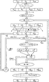
図5は、本発明の実施の形態に従って、1つのデータ・フレームからの第1サブセット・ビットに対応する符号化ビットおよび同データ・フレームからの第2のサブセット・ビットに対応する非符号化ビットを表すシンボルを含む逐次的に送信される複数のスロットを含む変調された信号を受信するための動作を示している。ブロック100で、第1スロットが受信機30によって受信される。受信されたスロットは次に、ブロック102に示すように第1パスの復調を施され、符号化ビット位置および非符号化ビットの位置を有する第1スロット推定値が提供される。1つのデータ・フレームからのビットが第1スロットと第2スロットの両方に含まれるインターリーブを用いるプロトコルに対して、スロット推定値はブロック106に示すようにデインターリーブされて、第1スロット推定値の符号化ビット位置はブロック108で復号されて第1の復号ビット推定値が提供される。
【0043】
ブロック110では、復号ビット推定値はCRC誤り検出法によるなどして誤りがテストされる。もしブロック108からのビット推定値に誤りが見つかれば、ブロック112において第1スロット推定値がバッファ・メモリ中へ再ロードされて、第1パスからの誤りを含む復号結果に基づいて第2パスの復調を実際に制限することなしに、マルチパス動作が通常の動作フローを継続することが許可される。あるいは、もし誤りが検出されなければ、動作はブロック114へ移動して、そこにおいて符号化ビット位置をブロック108からの第1の復号ビット推定値に等しいように制約する制約付き復調によって第2スロット推定値を提供するように第1スロットが再び復調される。復調は、第1の復号ビット推定値を第1スロットの推定値の非符号化ビット位置からのビットと組み合わせること、および再生されたスロットを提供するために、インターリーブ法の結果として受信されなかったデータ・フレームのビット・セグメントに対応する未知のビットを挿入することによって制約されよう。この再生されたスロットは、ブロック114において制約付き復調の間にトレリス遷移を制限するために使用されよう。
【0044】
ブロック116では、ブロック114における制約付き復調の出力がデインターリーブされる。ブロック118では、制約付き復調からのデインターリーブ出力符号化ビットが復号されて第2の符号化ビット推定値が提供される。ブロック118において第2パスの復号からの出力に誤りがない場合には、ブロック118からの第2の復号ビット推定値およびブロック114からの第2スロット推定値の非符号化ビット位置が組み合わされて受信機30からの受信データ・フレーム推定値が提供される。
【0045】
既に述べたように、本発明は2パスのマルチパス復調のみに限定されず、信頼性を高めるために付加的なパスを含むことができる。第1の実施の形態では、制約付き復調(ブロック114)および復号(ブロック118)の操作は、例えばカウンタが終了するまで、最近の復号工程からの復号ビット推定値を制約付き復調を制約するように再帰的に用いることによって反復することができる。次に、ブロック120における組み合わせる工程は、カウンタが終了する前の最後のパスからの復号ビット推定値の最終的な組を組み合わせることによって受信データ・フレームの推定値を提供する。あるいは、信頼性変化の基準が満たされるまで、操作を再帰的に続けることができる。例えば、マルチパス操作は、後続のパスでの信頼性変化が先行するパスに対する最小デルタ・レベル以下になるまで繰り返し継続することができる。
【0046】
図6は本発明の実施の形態に従って処理されるときに、音声フレームに起こることを模式的に示している。送信装置では、CRCコードに従って符号化された音声フレームFnは畳み込み符号化およびインターリーブを受けてスロットSnを形成し、現在の音声フレームFnおよび前の音声フレームFn-1から現在のSnが形成される。これらスロットはチャネル上を送信され、受信機30,30’によって受信される。
【0047】
受信されたスロットRnはバッファに記憶される。そのスロットは同期化され、イコライザ(復調器)を通されて、畳み込み復号およびデインターリーブが前の音声フレームFn-1に対応する再構築音声フレーム

![]()
【0048】
引き続く再構成音声フレーム
![]()
![]()
![]()
![]()
![]()
![]()
![]()
【0049】
第2パスの間に、イコライザは、畳み込み復号器の第1パスの出力から再構成されたスロットを受信する。図6で、それは、音声フレームFn-1および未知の音声フレームUnに対応する既知のクラス1ビット
![]()
![]()
![]()
【0050】
IS−136タイプの電話に関するイコライザのトレリスは2つのトップ・チャネルから形成されよう。従って、差動符号化された単一シンボルによって状態が形成され、1つの状態から別の状態への遷移は符号化前に情報シンボルによって決まる。このブランチ・ラベルは、受信された標本に対応するそのブランチでの白色化整合フィルタの出力と、そのブランチ遷移を引き起こした差動符号化コンステレーション・ポイント(constellation point)に対する白色化フィルタの応答との間のユークリッド距離の自乗によって与えられる。そのような状態遷移表が表1に示されている。
【0051】
【表1】
仮のスロットは、次のような任意の組合せで構成される4シンボルで構成される。
1.両ビットが既知;1状態からの1つのトレリス遷移出力のみが有効
2.2ビットの1つが既知;可能な4つのうち2つのトレリス遷移出力が有効
3.両ビットが未知;すべてのトレリス遷移が有効
【0053】
ここで図7に戻ると、本発明の実施の形態に従う、トレリス遷移を制約するために用いられる簡略化法が模式的に示されている。図7は、簡略化後の第2パスによって分かるようにイコライザ・トレリスの2つのステージを示しており、第1のものは第1パス復調後に4シンボルのうちの両ビットが未知の場合である。これらの未知のビットはトレリスの上にタグuというラベルを付けてある。第2ステージは1つの既知のビット0および1つの未知のビットuに対応しており、トレリスの上に(0,u)を用いて示されている。差動コンステレーション・ポイントに対応するトレリス状態は
![]()
【0054】
トレリス遷移は、無効な遷移を禁止するか、あるいはブランチのメトリック計算に大きなバイアスを与えることによって簡略化することができ、それによってその遷移の子は判定プロセスにおいて強制的に排除される。
【0055】
擬似コード表現がそれに続き、
![]()
【0056】
ブランチ・メトリックの計算毎に、そのメトリックに対して、次の式を使って擬似コードによって定義されるバイアスが加えられる。
【0058】
IS−136標準規格のようなプロトコルと一緒に本発明を使用すれば、クラス1Aおよびクラス1Bビットに対する仮判定に基づくクラス2のビット誤り率特性は改善される。いくつかのチャネル条件では、この結果のクラス2の誤り特性はクラス1Bの誤り特性よりも優れたものとなる。従って、或る条件下では、仮判定に対して異なるビット組を使用する第3および後続のパスによって、進歩した特性が提供されることになる。すなわち、クラス1Aおよびクラス2のビットに対してクラス1Bの誤り特性が改善される。更に、各種クラスのビットに対する判定の変更はマルチパスに亘って実行することができ、その結果、パス毎に誤り特性が徐々に向上することになる。そのような変更は本発明のスコープに含まれるものと理解されるべきである。
【0060】
既に述べたように、強制的なメトリック値を使用して変調に対する第2パスの制約を扱うことができる。しかし、理解すべきことは、別のやり方として、スロットの符号化ビット位置の1つに対応する場所にビット推定値を有し、それがその場所に対応する第1パスでの復号ビット推定値とは異なっている任意のビット経路候補を復調時に無視することによっても同じ結果が実現できるということである。第1パスにおける復調器および復号器からの硬出力に対しては、第1スロットの符号化ビット位置の1つに対応する場所にビット推定値を有し、それが第1パスの復号ビット推定値の関連するものとは異なっている任意のビット経路候補のメトリックをバイアスする代替法としてこの方式を利用することができる。
【0061】
本発明はまた、軟出力と一緒にビタビ(Viterbi)アルゴリズムを用いて、あるいは復号ビット推定値に対応する信頼性を提供するその他のタイプのアルゴリズムを用いて有利に実現することができる。それらの信頼性推定値は、引き続くパスで復調器によって使用される増分メトリックをバイアスするために使用されることが好ましい。メトリックに供給されるバイアスの大きさは、制約付き復調トレリスの各ステージに関する第1の復号ビット推定値の1つに付随する関連軟信頼値に基づいて決められよう。例えば、メトリックのバイアスは、指定された出力の信頼値に比例して増大されよう。これも述べたように、マルチパス操作は、カウンタが終了するまで、あるいは信頼性のそれ以上の改善が見込めなくなるまで繰り返されよう。
【0062】
本発明の別の態様では、第1パスの復調はイコライザ・タイプの復調器ではなく、差動復号器によって実行されよう。これは受信機動作の電力を節約し、更に、特にチャネル分散が低い条件下で、許容できる結果をもたらす。あるいは、差動復号器方式とイコライザ方式との間の切り替えは後続パスにおける改善の大きさに基づいて判定される。言い換えれば、第2パスで大きな改善が検出されれば、第1パスでは差動復号器よりもイコライザを使うように切り替えるのが好ましいであろう。これは、大きい改善が、第1パスの復調を差動復号器に依存するにはチャネル特性が不十分であることを示すためである。
【0063】
更に理解すべきことは、チャネル・トラッカ・タイプの復調器が本発明での使用に適しているということである。復調器のチャネル・トラッキングを制約することによって制約付き復調のフィードバックが提供されよう。チャネル・トラッカ用の復調器構造には2つのものがあって、一般に、状態当たり、または生き残り当たり1チャネルのモデル(CMS)形と、単一チャネルのモデル(SCM)形と呼ばれていることが知られている。本発明の利点は生き残り当たり(すなわち、CMS)構造を使用した場合に最も発揮されることが分かった。しかし、これが本発明を実施する好適な方式であるものの、本発明の利点は単一チャネル・モデル・タイプの復調器でも同様に実現できる。
【0064】
本発明はビタビ・アルゴリズムの変形の基づく復調器と一緒に使用することができる。例えば、Mアルゴリズムは、ソース符号化、チャネル復号、および復調で使用されてきたツリー状探索法である。Mアルゴリズムは、ビタビ・アルゴリズムを使用して実現される、最尤系列推定(MLSE)の複雑さを減らした近似法であるとみなすことができよう。L=2lとして、Lに関する変調方式についてこのアルゴリズムを説明する。ここでlビットが1つの変調シンボルsにマッピングされる。受信機では、長さDシンボルのシンボル間干渉を取り扱うことのできる2l(D-1)状態のトレリスを考える。各状態は各々、異なるシンボルでラベルを付けられた2lブランチのファン・アウトと、すべて同じシンボルでラベルを付けられた2lブランチのファン・インを有する。
【0065】
IS−136では、例えば、l=2で、従ってL=4である。Dの値は典型的にはビタビ・アルゴリズムに対して、その複雑さを管理できるように保つために2に選ばれる。その結果、トレリスは4状態を取ることになる。しかし、Dに対して3や4のようなもっと大きい値を選び、端数間隔のチャネル分散によって引き起こされるシンボル間干渉および受信機フィルタ作用をより多く考慮することによって、より優れた結果を得ることもできる。
【0066】
Mアルゴリズムは典型的には次のように働く:典型的には2l(D-1)の小部分である何らかのM値に対して、トレリスのn−1ステージにおいて、σ1 n-1,...,σM n-1と表記されるM個の生き残り状態がある。それらの累積メトリックはc1 n-1,...,cM n-1で表記される。各状態から、2lの出力ブランチがある。このように、ステージnにおいて到達する個別状態数Vは変数であり、それは2lからM2lの範囲にある。更に、到達した各状態は1および2lブランチの間のファン・インfを有する。f個の経路メトリック候補があり、各々がそのブランチの開始状態の経路メトリックにブランチ・メトリックを加えたものに等しくなっている。その状態に関して最も小さいメトリック候補を見つけるためには、f個の比較が必要である。(アルゴリズムの構造を単純化するために、第1のメトリック候補と大きい公称値との些細な比較を含む)。最小メトリックに対応する経路はここで生き残り経路であり、その状態で終了する。すべての状態を考慮すると、比較の数はM2lとなる。また、すべての状態について、M2lのブランチ・メトリック計算(各々が複数の加算および/または乗算を要する)とM2lの加算がある。最後に、もしV>Mであれば、V状態のうちで、最小の累積メトリックc1 n-1,...,cM n-1を有するM状態σ1 n,...,σM nがステージnにおいて生き残る。(複雑な推定値を管理可能に保つように、常にM個の生き残り状態があることが仮定されている。この結果、複雑さが過大推定される。)
【0067】
参考までに、ビタビ・アルゴリズムにおいて、一般に状態毎に2lのブランチ・メトリック計算があり、合計で2l(D-1)2lとなる。各状態は典型的には、合計で2l(D-1)2lの経路メトリック候補を生成するために2lの加算を必要とする。
【0068】
復調からのフィードバックは本発明に従ってMアルゴリズムを修正するために使用されよう。例えばD=3の場合に、IS−136では、完全なトレリスは16状態を有する。特性にできるだけ影響しないように、できるだけ小さいM値として4を選ぶことができる。
【0069】
1つの実施の形態では、第1パス復号器からのフィードバックは硬判定の形で行われる。すなわち、復号器は復調器に対して、特殊なビット(例えば104)が既知であることを伝える。復調器はこの知識を利用して、それが出力できる可能なシーケンス組を制限する。これを行う効率的な方法は、復調器からのフィードバックに従って、発生できないブランチを簡略化することによってトレリスを制約するものである。
【0070】
Mアルゴリズムは、本発明に従う制約されたトレリスを有利に実現することができる。上述のように、トレリスの制約されないステージに対して各状態は2lブランチのファン・アウトを有する。そのステージについてのl個のうちiビットが既知であれば、各ファン・アウトは2l-1に削減される。従って、M2l-1の比較、M2l-1のブランチ・メトリック計算、およびM2l-1の加算が行われよう。もしこのステージの最初にM2iの生き残り状態が存在していれば、これらの数字は初期の数字へ押し戻すことができる。トレリス・ステージの制約は予め分かっているので、本発明の方法に従って制約付き復調を実現するように各ステージに対する生き残り状態の数を指定することができる。
【0071】
生き残りステージの数を2iだけ増やす効果は、探索空間が復号器からのフィードバックに照らして許容できると考えられるシーケンスに亘って成長することを許容されることを意味する。事実、Mアルゴリズムと復号器フィードバックとの組合せは許容できるシーケンスに亘って適用されるMアルゴリズムとして理解されよう。これはコード化および非コード化変調方式に直接的に適用される。それは更に、内側のコードが復調の役目を果たすようになったカスケード・コードを用いる方式にも適用される。更に、上の説明のコード化方式は畳み込みまたはブロック式のコードでよく、2進数でよく、あるいはより大きな文字集団に亘って動作することができる。本発明は、IS−136標準規格のようにトラッキング付きの、あるいはGSM標準規格のようにトラッキングなしのコヒーレント復調と互換性を持つ。
【0072】
図面および説明の中で、本発明の典型的な好適な実施の形態が開示され、また特殊な用語が用いられているが、それらは一般的な意味で、また説明の便宜上のためであって限定的な意味を持たない。本発明のスコープは特許請求の範囲に定義される。
【図面の簡単な説明】
【図1A】 IS−136標準規格に従う音声コード化システムのブロック図。
【図1B】 IS−641標準規格に従う音声コード化システムのブロック図。
【図2】 本発明の実施の形態に従う受信機のブロック図。
【図3】 図3の受信機の第1の実施の形態の詳細なブロック図。
【図4】 図3の受信機の第2の実施の形態の詳細なブロック図。
【図5】 本発明の実施の形態に従って変調信号を受信するための操作を示すフローチャート。
【図6】 本発明に従うマルチパス受信機の実施の形態に関するプロセス・フローを示す模式図。
【図7】 本発明の実施の形態に従う復調器トレリスの簡略化を示す模式図。[0001]
(Field of Invention)
The present invention relates to telecommunications systems, and more particularly to systems and methods for receiving modulated signals.
[0002]
(Background of the Invention)
Public radiotelephone systems are widely adopted to provide voice and data communications to subscribers. For example, it has been a long time since analog cellular radiotelephone systems such as AMPS, ETACS, NMT-450, and NMT-900 have been successfully deployed around the world. Digital cellular radiotelephone systems such as those according to the North American standard IS-54 and the European standard GSM have been in service since the early 1990s. More recently, various wireless digital services widely called PCS (Personal Communication Service) have been introduced, among them advanced digital cellular phones that comply with standards such as IS-136 and IS-95. Included are systems, low power systems such as DECT (digital enhanced cordless telephone), and data communication services such as CDPD (cellular digital packet data). These and other systems are described in "The Mobile Communications Handbook" (1996) by Gibson, CRC Press Publishing.
[0003]
A wireless telecommunications system, such as a cellular radiotelephone system, typically includes multiple communication channels established between a first transceiver (eg, a base station) and a second transceiver (eg, a mobile terminal). . Communication channels are generally exposed to environmental effects that degrade characteristics such as multipath fading and interference (noise). The fading effect includes flat fading caused by the transmitted signal (chief ray) interacting with the reflection of the transmitted signal arriving at the receiver at the same time. Another type of fading, time dispersion, is caused by the interaction of the chief ray with the reflection of the chief ray delayed in time. Interference effects are caused by the interaction of non-orthogonal signals generated in the signal medium by signal sources other than the desired transmission signal source. Time dispersion can be compensated using an equalization method such as maximum likelihood sequence estimation (MLSE). Interference can be reduced by adjusting the antenna beam to reduce the reception of unwanted signals.
[0004]
Fading is generally the main cause of degrading the characteristics of a demodulator in a telecommunications system. The mobile terminal receiver typically includes a demodulator that is a coherent demodulator, such as a maximum likelihood sequence estimator (MLSE) demodulator (or equalizer). In order to reliably demodulate the received signal, the demodulator is usually provided with an associated channel tracker. After obtaining the transmitted signal at the receiver, the channel tracker maintains a channel estimate to provide a coherent correlation between the demodulator and the received signal.
[0005]
Combining demodulation and decoding by feeding back from the decoder to the demodulator is one way to improve the receiver characteristics. This may be achieved by multi-pass demodulation. According to information theory, an optimal receiver performs a combination of demodulation and decoding operations. Such operational complexity is particularly noticeable when interleaving is performed in the system. However, by providing feedback from the decoder to the demodulator, it is possible to bridge part of the gap between separate demodulation and decoding and combined demodulation and decoding. This is the concept behind multipath demodulation.
[0006]
Examples of such multipath demodulationDeU.S. Pat. No. 5,673,291 to Dent. The '291 patent first provides information to the demodulator by demodulating the received signal, then decoding the coded symbols, and then re-encoding the decoder output. It describes re-demodulating uncoded symbols with good characteristics. The re-encoded symbol is used as a known symbol having excellent characteristics. The re-encoded symbols are exploited as known symbols by the demodulator in the same way that they exploit the synchronization symbols, which are truly known symbols inserted into the data prior to transmission. The method and system of this' 291 patent is generally based in part on the receiver's knowledge of the order of symbols to place in the transmitted signal stream and based on the placement of any known synchronization symbols. ing. Alternatively, Garr et al. Have proposed a multi-path demodulator for bit streams that is fully encoded with soft feedback to the demodulator. “Iterative Decoding of GSM Signals” published in March 1988 at a conference on information science and systems at Princeton University. Yet another proposed scheme is, for example, “Near Shannon Limit Error Correction Coding and Decoding: Turbo Code (1)” by Berrou et al. Published on pages 1064-1070 of the 1993 IEEE International Conference Conference Proceedings. Near Shannon Limit Error-correcting Coding and Decoding: Turbo-codes (1)) ”, which proposes the use of turbo codes using parallel concatenation of two recursive convolutional codes. Similarly, the serial concatenation of two recursive convolutional codes was published by Benedetto et al. On August 15, 1996 in TDA Progress Report 42-126 at the University of Turin, Italy. Characteristic Analysis, Design, and Iterative Decoding (Serial Connection of Interleaved Codes: performance Analysis, Design and Iterative Decoding) ”.
[0007]
There are problems with those proposed in the '291 patent and with communication systems that include uncoded bit classes. Examples of such codes associated with various currently proposed telecommunication standards are shown in FIGS. 1A and 1B. FIG. 1A shows an example speech coding system described for the IS-136 standard. FIG. 1B shows a similar format for the IS-641 standard. As shown in FIG. 1A, the
[0008]
The IS-641 standard coding structure will now be described with reference to FIG. 1B. The adaptive code excited linear prediction (ACELP)
European Patent Application No. EP0 802 656, International Publication No. WO98 / 48517 and US Piscataway, IEEE Communications Letters issued by the IEEE Service Center,
[0009]
While these various schemes have the potential to achieve advanced signal reception, there continues to be a need to improve the performance of receivers for modulated signals containing encoded and uncoded data. As yet another requirement, such improvements must be usable with existing communication protocol standards.
[0010]
(Summary of Invention)
Accordingly, one object of the present invention is to provide a method and system for receiving a modulated signal including coded and uncoded bits using a multipath demodulator to address the problem of reception errors in a wireless communication system. Is to solve it by providing
[0011]
An additional object of the present invention is to provide such a system and method that can be used in conjunction with existing communication protocol standards.
[0012]
Yet another object of the present invention is to provide such a system and method that can be advantageously used with an MLSE type demodulator that provides both hard and soft output information.
[0013]
Yet another object of the present invention is to obtain an efficient high performance receiver by combining the reduced complexity of the M algorithm in the demodulator with the feedback information of the multipath demodulation.
[0014]
These and other objects are in accordance with the present invention to receive a first received signal for receiving a modulated signal containing symbols representing both encoded and uncoded bits from a single data (eg, speech) frame. Provided by providing a method and system for demodulating a slot and decoding encoded bits. The decoded bits are then used to constrain demodulation during the second demodulation of the received 1 slot. The encoded bit position from the constrained second demodulation is then encoded to generate a bit estimate for the received slot. This information is combined with the output of the constrained second demodulation of uncoded bits to produce a received data frame estimate that has been shown to provide high reliability of both coded and uncoded bits. provide.
[0015]
In particular, sequentially transmitted including symbols representing encoded bits corresponding to the first subset bits from one data frame and uncoded bits corresponding to the second subset bits from the same data frame. A method is provided for receiving a modulated signal including a plurality of slots. A first slot is received and demodulated to provide a first slot estimate having a coded bit position and an uncoded bit position. The encoded bit position of the first slot estimate is decoded to provide a first decoded bit estimate. The first slot is then demodulated constrained, preferably by convolution, having a coded bit position and an uncoded bit position, the second slot estimate of the encoded bit position being in accordance with the first decoded bit estimate. A constrained second slot estimate is provided. The encoded bit position of the second slot estimate is decoded to provide a second decoded bit estimate, which is combined with the uncoded bit position of the second slot estimate to provide the received data frame estimate. .
[0016]
According to another embodiment of the method of the present invention, after decoding to obtain a first slot estimate, some error is detected in the first decoded bit estimate and an error is detected Does not use the encoded bit position of the second slot estimate to generate the second decoded bit estimate. Error detection includes including at least one error detection bit, such as a CRC bit, in the first decoded bit estimate and performing error detection in the first decoded bit estimate based on the at least one error detection bit. Will be offered.
[0017]
A constrained demodulation operation according to an embodiment of the present invention has a bit estimate at a location corresponding to one of the encoded bit positions of the first slot, which is associated with the first decoded bit estimate. Can include ignoring any bit path candidates that are different during demodulation. Alternatively, any bit path candidate metric that has a bit estimate at a location corresponding to one of the encoded bit positions of the first slot, which is different from the associated one of the first decoded bit estimate Can bias the bit path candidates away. Furthermore, the decoder can output an associated soft confidence value for each of the first decoded bit estimates, whereby the first slot corresponds to one of the encoded bit positions of the first slot. A metric for any bit path candidate that has a bit estimate at a location that is different from the associated one of the first decoded bit estimate is the softness associated with the associated one of the first decoded bit estimate. By biasing based on the confidence value, constrained demodulation will occur in a convolutional manner.
[0018]
In another embodiment of the present invention, the second slot estimate is used to constrain the constrained demodulation until the recursive counter reaches an upper limit using the iteration of the constrained demodulation, the decoded bit estimate from the most recent decoding step. Multipath demodulation recursed by decoding received coded bit positions and providing received frame estimates by combining the final set of decoded and uncoded bit estimates for the last slot estimate Provided by Alternatively, the recursive operation will continue until the reliability criteria are met. The reliability criterion may be performance.
[0019]
In another aspect, a first demodulation operation is performed using a differential decoder. Alternatively, if the reliability criteria are met, a differential decoder will be used, otherwise a convolutional decoder will be used. The present invention may be used with per-survivor processes in constrained demodulation operations. Further, a separate buffer memory may be used for each demodulation path, or a single buffer memory may be overwritten for each path.
[0020]
The advantages of the present invention in another embodiment may be realized when the transmission slot includes interleaved data transmission. The first slot will be received before the second slot. The first decoded bit estimate, the bit from the uncoded bit position of the first slot estimate, and the unknown bit corresponding to the second segment bit are combined to provide a playback slot, limiting trellis transitions during demodulation Thus, using this playback slot will constrain the constrained demodulation operation. Alternatively, trellis transition constraints during demodulation may be done by biasing the metric of the selected bit path candidate based on the recovered slot.
[0021]
In another embodiment of the present invention, the first slot is demodulated with trellis constraints using an M algorithm with multiple trellis stages. The number of surviving states for at least one of the multiple trellis stages will be specified. Also, the number of surviving states for multiple trellis stages will be specified so that only acceptable paths are allowed to survive as surviving states.
[0022]
In another aspect of the invention, a method is provided for receiving a modulated signal comprising a plurality of slots that are transmitted sequentially. A first slot is received and demodulated to provide a first slot estimate. The first slot estimate is decoded to provide a first decoded bit estimate. The first slot is then constrained demodulated to provide a second slot estimate, where a plurality of bit positions in the second slot estimate are equal to corresponding ones in the first decoded bit estimate. Constrained by The second slot estimate is decoded to provide a received data frame estimate. The constrained demodulation and decoding operations for the second slot estimate are recursively repeated using the data frame estimate for constraining the constrained demodulation process.
[0023]
In a systematic aspect of the present invention, symbols representing coded bits corresponding to a first subset bit from one data frame and uncoded bits corresponding to a second subset bit from the same data frame are represented. A receiver is provided for receiving a modulated signal including a plurality of sequentially transmitted slots. The receiver includes a receiver circuit configured to receive a transmitted slot, and a first demodulator coupled to the receiver and configured to generate a first slot estimate from the received slot. Including. A first decoder is coupled to the demodulator to provide a first decoded bit estimate from the first slot estimate and the constraint slot. A constrained demodulator configured to generate a second slot estimate based on the constrained slot is also provided. A second decoder coupled to a constrained demodulator is provided that is adapted to provide a second decoded bit estimate from the second slot estimate. Means are also included for combining the second decoded bit estimate and an uncoded bit position of the second slot estimate to provide a received data frame estimate.
[0024]
Although the present invention has been described above primarily in terms of method aspects, it should be understood that the present invention also encompasses system aspects including systems configured to perform the methods of the present invention. Thus, the present invention provides a novel approach to multipath demodulation that provides improved receiver performance.
[0025]
(Detailed description of the invention)
The present invention will now be described more fully with reference to the accompanying drawings, in which preferred embodiments of the invention are shown. It should be understood, however, that the invention can be embodied in many forms and should not be construed as limited to the embodiments set forth herein, but rather these embodiments form a complete body of the disclosure. And is provided to fully convey the scope of the invention to those skilled in the art. As will be appreciated by those skilled in the art, the present invention can be implemented as a method or as an apparatus. Therefore, the present invention can take an embodiment as hardware, an embodiment as software, or an embodiment in which both software and hardware are combined.
[0026]
The operation of the present invention operates here mainly in ACELP format speech frames (as specified in the IS-641 standard mentioned above with reference to FIG. 1B) and includes encoded and uncoded bits. Will be described. However, the advantages of the present invention can also be realized in mobile terminals operating in other communication systems that use modulated signals transmitted over channels that are subject to noise, fading, and other channel effects.
[0027]
FIG. 2 shows an embodiment of a receiver according to the invention. As shown in the embodiment of FIG. 2, the
[0028]
For an interleaved communication format as defined in ACELP, the output slot estimate from the
[0029]
The output coded bits from the second
[0030]
It should be understood that although not shown, the outputs of
[0031]
To facilitate an understanding of the present invention, two-pass demodulation will now be generally described. At the transmitter, the coded and uncoded bits of speech frame n are interleaved across modulator bursts n and n + 1. At the receiver, in
[0032]
The inventors of the present invention have demonstrated that the error performance for both
[0033]
Referring now to FIG. 3, the base band section of the
![]()
![]()
[0034]
Referring now to FIG. 3, the
[0035]
As is apparent from the embodiments of FIGS. 3 and 4, the receiver configuration is adapted to use one equalizer and decoder for each of the two paths of multipath demodulation. Each path of the multipath demodulation operates on the same first slot of received information received by the
[0036]
With respect to the embodiment of FIG. 3, the
[0037]
If the second pass is allowed, the output of
![]()
![]()
[0038]
FIG. 4 shows an alternative embodiment 30 'of the
![]()
[0039]
As will be apparent to those skilled in the art, the above-described aspects of the invention illustrated in FIGS. 2-4 may be provided by hardware, software, or a combination thereof. Although the various components of the
[0040]
Exemplary operations according to aspects of the present invention will now be described with respect to the flowchart of FIG. It will be understood that each block in the flowchart diagram, and combinations of blocks shown in the flowchart, can be implemented by computer program instructions. Those program instructions are provided to the processor to constitute a machine, whereby the instructions executed on the processor generate means for implementing the functions specified in one or more blocks of the flowchart. Computer program instructions are executed by a processor, and a series of operations are executed by the processor to generate a process incorporated in the computer, whereby instructions executed on the processor are executed in one or more blocks of the flowchart. A process for realizing the specified function is provided.
[0041]
Accordingly, the flowchart diagram blocks support a combination of means for executing the specified function, a combination of steps for executing the specified function, and a program instruction means for executing the specified function. As will be appreciated, each block of the flowchart diagram, combinations of blocks in the flowchart diagram, can be determined by a system based on special purpose hardware that implements a specified function or process, or special purpose hardware and computer instructions. It can be realized by a combination of
[0042]
FIG. 5 illustrates encoded bits corresponding to a first subset bit from one data frame and uncoded bits corresponding to a second subset bit from the data frame according to an embodiment of the present invention. FIG. 6 illustrates an operation for receiving a modulated signal including a plurality of sequentially transmitted slots including symbols representing. At
[0043]
At
[0044]
In
[0045]
As already mentioned, the present invention is not limited to only two-path multipath demodulation, but can include additional paths to increase reliability. In the first embodiment, the operations of constrained demodulation (block 114) and decoding (block 118) are constrained to constrained demodulation with decoded bit estimates from the most recent decoding step, eg, until the counter is finished. Can be repeated by using it recursively. Next, the combining step in
[0046]
FIG. 6 schematically illustrates what happens to a voice frame when processed in accordance with an embodiment of the present invention. In the transmitting device, the voice frame F encoded according to the CRC code.nIs subjected to convolutional coding and interleaving in slot SnAnd the current voice frame FnAnd previous voice frame Fn-1To current SnIs formed. These slots are transmitted over the channel and received by
[0047]
Received slot RnIs stored in a buffer. The slot is synchronized, passed through an equalizer (demodulator) and subjected to convolutional decoding and deinterleaving for the previous speech frame F.n-1Reconstructed audio frame corresponding to
![]()
[0048]
Subsequent reconstructed audio frames
![]()
![]()
![]()
![]()
![]()
![]()
![]()
[0049]
During the second pass, the equalizer receives a reconstructed slot from the output of the first pass of the convolutional decoder. In FIG. 6, it is a voice frame Fn-1And unknown speech frame UnKnown
![]()
![]()
![]()
[0050]
The equalizer trellis for an IS-136 type phone will be formed from two top channels. Thus, a state is formed by a single symbol that is differentially encoded, and the transition from one state to another depends on the information symbol before encoding. This branch label is the output of the whitened matched filter at that branch corresponding to the received sample and the response of the whitened filter to the differential coding constellation point that caused the branch transition. Is given by the square of the Euclidean distance between. Such a state transition table is shown in Table 1.
[0051]
[Table 1]
The temporary slot is composed of 4 symbols that are composed of the following arbitrary combinations.
1. Both bits are known; only one trellis transition output from one state is valid
2.2 One known bit; 2 out of 4 possible trellis transition outputs are valid
3. Both bits are unknown; all trellis transitions are valid
[0053]
Returning now to FIG. 7, there is schematically shown a simplified method used to constrain trellis transitions according to an embodiment of the present invention. FIG. 7 shows the two stages of the equalizer trellis as can be seen by the simplified second pass, the first being the case where both bits of the four symbols are unknown after the first pass demodulation. . These unknown bits are labeled on the trellis with the tag u. The second stage corresponds to one known
![]()
[0054]
Trellis transitions can be simplified by prohibiting invalid transitions or by providing a large bias in the branch metric calculation, thereby forcing the children of the transition to be excluded in the decision process.
[0055]
Pseudocode representation follows,
![]()
[0056]
For each branch metric calculation, a bias defined by the pseudo code is applied to the metric using the following formula:
[0058]
If the present invention is used in conjunction with a protocol such as the IS-136 standard, the
[0060]
As already mentioned, a forced metric value can be used to handle the second pass constraints on the modulation. However, it should be understood that, as an alternative, the bit estimate is in a location corresponding to one of the encoded bit positions of the slot, which is the decoded bit estimate in the first pass corresponding to that location. This means that the same result can be achieved by ignoring any bit path candidates that are different from those in the demodulation. For the hard output from the demodulator and decoder in the first pass, it has a bit estimate at a location corresponding to one of the encoded bit positions in the first slot, which is the decoded bit estimate in the first pass. This scheme can be used as an alternative to biasing the metric of any bit path candidate that is different from the value associated.
[0061]
The present invention can also be advantageously implemented using the Viterbi algorithm with soft output or other types of algorithms that provide reliability corresponding to the decoded bit estimates. Those reliability estimates are preferably used to bias the incremental metrics used by the demodulator in subsequent passes. The magnitude of the bias supplied to the metric may be determined based on the associated soft confidence value associated with one of the first decoded bit estimates for each stage of the constrained demodulation trellis. For example, the metric bias may be increased in proportion to the specified output confidence. As also mentioned, the multi-pass operation will be repeated until the counter is finished or no further improvement in reliability can be expected.
[0062]
In another aspect of the invention, the first pass demodulation may be performed by a differential decoder rather than an equalizer type demodulator. This saves receiver operation power and also provides acceptable results, especially under conditions of low channel dispersion. Alternatively, switching between the differential decoder scheme and the equalizer scheme is determined based on the magnitude of the improvement in subsequent passes. In other words, if a significant improvement is detected in the second pass, it may be preferable to switch to using an equalizer rather than a differential decoder in the first pass. This is because the large improvement shows that the channel characteristics are insufficient to rely on the differential decoder for the first pass demodulation.
[0063]
It should be further understood that a channel tracker type demodulator is suitable for use in the present invention. By constraining the demodulator channel tracking, constrained demodulation feedback may be provided. There are two demodulator structures for channel trackers, commonly referred to as a one channel model (CMS) form per state or survivor and a single channel model (SCM) form It has been known. It has been found that the advantages of the present invention are most exhibited when using a per surviving (ie, CMS) structure. However, although this is the preferred way of practicing the present invention, the advantages of the present invention can be realized in a single channel model type demodulator as well.
[0064]
The present invention can be used with a demodulator based on a variation of the Viterbi algorithm. For example, the M algorithm is a tree-like search method that has been used in source coding, channel decoding, and demodulation. The M algorithm could be viewed as an approximation that reduces the complexity of maximum likelihood sequence estimation (MLSE), realized using the Viterbi algorithm. L = 2lThis algorithm will be described with respect to the modulation scheme for L. Here, 1 bit is mapped to one modulation symbol s. The receiver can handle intersymbol interference of
[0065]
In IS-136, for example, l = 2 and therefore L = 4. The value of D is typically chosen to be 2 for the Viterbi algorithm in order to keep its complexity manageable. As a result, the trellis takes four states. However, better results can also be obtained by choosing a larger value for D, such as 3 or 4, and more considering intersymbol interference and receiver filtering effects caused by fractionally spaced channel dispersion. it can.
[0066]
The M algorithm typically works as follows: typically 2l (D-1)For any M value that is a small part of1 n-1,. . . , ΣM n-1There are M survival states denoted as Their cumulative metric is c1 n-1,. . . , CM n-1It is written with. From each state, 2lThere are output branches. Thus, the number of individual states V reached in stage n is a variable, which is 2lTo M2lIt is in the range. Furthermore, each state reached is 1 and 2lHas a fan-in f between branches. There are f path metric candidates, each equal to the starting path metric of the branch plus the branch metric. To find the smallest metric candidate for that state, f comparisons are required. (Includes a trivial comparison between the first metric candidate and a large nominal value to simplify the algorithm structure). The path corresponding to the minimum metric is now a surviving path and ends in that state. Considering all states, the number of comparisons is M2lIt becomes. For all states, M2lBranch metric computation (each requires multiple additions and / or multiplications) and M2lThere is an addition. Finally, if V> M, the smallest cumulative metric c in the V state1 n-1,. . . , CM n-1M state σ having1 n,. . . , ΣM nSurvive at stage n. (It is assumed that there are always M surviving states so as to keep the complex estimates manageable. This results in overestimation of complexity.)
[0067]
For reference, in the Viterbi algorithm, generally 2 per statelThere are 2 branch metric calculations, for a total of 2l (D-1)2lIt becomes. Each state is typically 2 in
[0068]
Feedback from demodulation will be used to modify the M algorithm in accordance with the present invention. For example, when D = 3, in IS-136, a complete trellis has 16 states. In order not to affect the characteristics as much as possible, 4 can be selected as the smallest M value possible.
[0069]
In one embodiment, the feedback from the first pass decoder is in the form of a hard decision. That is, the decoder tells the demodulator that a special bit (eg, 104) is known. The demodulator uses this knowledge to limit the possible sequence sets it can output. An efficient way to do this is to constrain the trellis by simplifying branches that cannot occur, according to feedback from the demodulator.
[0070]
The M algorithm can advantageously implement a constrained trellis according to the present invention. As described above, each state is 2 for the unconstrained stage of the trellis.lHave a fan-out of the branch. If i bits out of l for that stage are known, each fan-out is 2l-1To be reduced. Therefore, M2l-1Comparison of M2l-1Branch metric calculation and M2l-1Will be added. If at the beginning of this stage M2iThese numbers can be pushed back to the initial numbers if there is a surviving state. Since the trellis stage constraints are known in advance, the number of surviving states for each stage can be specified to achieve constrained demodulation in accordance with the method of the present invention.
[0071]
Number of survival stages is 2iThe effect of increasing only means that the search space is allowed to grow over a sequence that is considered acceptable in view of feedback from the decoder. In fact, the combination of the M algorithm and decoder feedback will be understood as an M algorithm applied over an acceptable sequence. This applies directly to coded and uncoded modulation schemes. It also applies to schemes using cascade codes where the inner code has become a demodulator. Further, the coding scheme described above can be a convolutional or block code, can be binary, or can operate over a larger character set. The present invention is compatible with coherent demodulation with tracking as in the IS-136 standard or without tracking as in the GSM standard.
[0072]
In the drawings and description, there have been disclosed exemplary preferred embodiments of the invention and specific terminology used in a general sense and for convenience of description. Does not have a limiting meaning. The scope of the invention is defined in the claims.
[Brief description of the drawings]
FIG. 1A is a block diagram of a speech coding system in accordance with the IS-136 standard.
FIG. 1B is a block diagram of a speech coding system according to the IS-641 standard.
FIG. 2 is a block diagram of a receiver according to the embodiment of the present invention.
FIG. 3 is a detailed block diagram of the first embodiment of the receiver of FIG. 3;
4 is a detailed block diagram of a second embodiment of the receiver of FIG. 3;
FIG. 5 is a flowchart illustrating operations for receiving a modulated signal according to an embodiment of the present invention.
FIG. 6 is a schematic diagram illustrating a process flow for an embodiment of a multipath receiver according to the present invention.
FIG. 7 is a schematic diagram showing simplification of a demodulator trellis according to an embodiment of the present invention.
Claims (30)
第1スロットを受信する工程(100)、
前記第1スロットを復調して、符号化ビット位置および非符号化ビット位置を有する第1スロット推定値を提供する工程(102)、
前記第1スロット推定値の前記符号化ビット位置を復号して、第1の復号ビット推定値を提供する工程(108)、
を含み、次の
前記第1スロットをトレリス制約付き復調して、符号化ビット位置および非符号化ビット位置を有する第2スロット推定値を提供する工程(114)であって、符号化ビット位置の前記第2スロット推定値が前記第1の復号ビット推定値に従って、少なくとも次の1つによって制約される工程、
(a)前記第1スロットの前記符号化ビット位置の1つに対応する場所にビット推定値を有し、それが前記第1の復号ビット位置の関連するものとは異なっている少なくとも1つのビット経路候補を、前記ビット推定値が前記第1の復号ビット推定値の前記関連するものと異なっているという判定に応じて、復調の間に無視する工程、および
(b)前記第1スロットの前記符号化ビット位置の1つに対応する場所にビット推定値を有し、それが前記第1の復号ビット位置の関連するものとは異なっている少なくとも1つのビット経路候補のメトリックをバイアスし、前記ビット推定値が前記第1の復号ビット推定値の前記関連するものと異なっているとする判定に応じて前記少なくとも1つのビット経路候補を敬遠する工程、
前記第2スロット推定値の前記符号化ビット位置を復号して、第2の復号ビット推定値を提供する工程(118)、および
前記第2の復号ビット推定値を前記第2スロット推定値の前記非符号化ビット位置と組み合わせて、受信データ・フレーム推定値を提供する工程(120)、を含むことを特徴とする方法。Sequentially transmitted including symbols representing encoded bits corresponding to the first subset bits from one data frame and uncoded bits corresponding to the second subset bits from the same data frame A method for receiving a modulated signal including a plurality of slots, comprising:
Receiving the first slot (100) ;
Demodulating the first slot to provide a first slot estimate having a coded bit position and an uncoded bit position (102) ;
Decoding the encoded bit position of the first slot estimate to provide a first decoded bit estimate (108) ;
Comprising : trellis constrained demodulating the next first slot to provide a second slot estimate having a coded bit position and an uncoded bit position (114) , comprising: The second slot estimate of the bit position is constrained by at least one of the following according to the first decoded bit estimate :
(A) at least one bit having a bit estimate at a location corresponding to one of the encoded bit positions of the first slot, which is different from the associated one of the first decoded bit positions Ignoring path candidates during demodulation in response to determining that the bit estimate is different from the associated one of the first decoded bit estimates; and
(B) at least one bit having a bit estimate at a location corresponding to one of the encoded bit positions of the first slot, which is different from the associated one of the first decoded bit positions Biasing a metric of a path candidate and shunting the at least one bit path candidate in response to determining that the bit estimate is different from the related one of the first decoded bit estimates;
Decoding the encoded bit position of the second slot estimate to provide a second decoded bit estimate (118) ; and calculating the second decoded bit estimate to the second slot estimate method characterized in that in combination with non-coding bit position, providing a received data frame estimate (120), the.
前記送信されたスロットを受信するように構成された受信機(32,50,52,34)、
前記受信機(32)へつながれて、受信したスロットから第1スロット推定値を生成するように構成された第1復調器(54)、
前記復調器(54)へつながれて前記第1スロット推定値および制約スロットから第1の復号ビット推定値を提供する第1復号器(62)、
を含み、前記システムが
前記制約スロットに基づいて第2スロット推定値を生成するように構成されたトレリス制約付き復調器(54)、であって符号化ビット位置の前記第2スロット推定値が少なくとも次の1つによって、前記第1の復号ビット推定値に従って制約されるようになっており、
(a)前記第1スロットの前記符号化ビット位置の1つに対応する場所にビット推定値を有し、それが前記第1の復号ビット位置の関連するものとは異なっている少なくとも1つのビット経路候補を、前記ビット推定値が前記第1の復号ビット推定値の前記関連するものと異なるとする判定に応じて、復調の間に無視する工程、および
(b)前記第1スロットの前記符号化ビット位置の1つに対応する場所にビット推定値を有し、それが前記第1の復号ビット位置の関連するものとは異なっている少なくとも1つのビット経路候補のメトリックをバイアスし、前記ビット推定値が前記第1の復号ビット推定値の前記関連するものと異なるとする判定に応じて前記少なくとも1つのビット経路候補を敬遠する工程、
前記制約付き復調器(54)へつながれて、前記第2スロット推定値から第2の復号ビット推定値を提供する第2復号器(62)、および
前記第2スロット推定値の第2の復号ビット推定値と非符号化ビット位置とを組み合わせて受信データ・フレーム推定値を提供する手段(64,64’、65 )、
を特徴とする受信機システム(30,30’)。A plurality of sequentially transmitted symbols including symbols representing encoded bits corresponding to a first subset bit from a data frame and uncoded bits corresponding to a second subset bit from the data frame A receiver system (30, 30 ') for receiving a modulated signal including a slot, comprising:
A receiver (32 , 50 , 52 , 34) configured to receive the transmitted slot;
A first demodulator (54) coupled to the receiver (32) and configured to generate a first slot estimate from the received slot;
A first decoder (62) coupled to the demodulator (54) to provide a first decoded bit estimate from the first slot estimate and the constraint slot;
A trellis constrained demodulator (54) , wherein the system is configured to generate a second slot estimate based on the constrained slot, wherein the second slot of coded bit positions The estimate is constrained according to the first decoded bit estimate by at least one of the following:
(A) at least one bit having a bit estimate at a location corresponding to one of the encoded bit positions of the first slot, which is different from the associated one of the first decoded bit positions Ignoring path candidates during demodulation in response to determining that the bit estimate is different from the associated one of the first decoded bit estimates; and
(B) at least one bit having a bit estimate at a location corresponding to one of the encoded bit positions of the first slot, which is different from the associated one of the first decoded bit positions Biasing a metric of a path candidate and refraining from the at least one bit path candidate in response to determining that the bit estimate is different from the associated one of the first decoded bit estimates;
A second decoder (62) coupled to the constrained demodulator (54) to provide a second decoded bit estimate from the second slot estimate; and a second decoded bit of the second slot estimate Means (64, 64 ', 65 ) for combining the estimate and the uncoded bit position to provide a received data frame estimate;
Receiver system (30, 30 ') characterized by
Applications Claiming Priority (3)
| Application Number | Priority Date | Filing Date | Title |
|---|---|---|---|
| US09/201,651 | 1998-11-30 | ||
| US09/201,651 US6366624B1 (en) | 1998-11-30 | 1998-11-30 | Systems and methods for receiving a modulated signal containing encoded and unencoded bits using multi-pass demodulation |
| PCT/US1999/024170 WO2000033527A1 (en) | 1998-11-30 | 1999-10-15 | Systems and methods for receiving a modulated signal containing encoded and unencoded bits using multi-pass demodulation |
Publications (2)
| Publication Number | Publication Date |
|---|---|
| JP2002532007A JP2002532007A (en) | 2002-09-24 |
| JP4339521B2 true JP4339521B2 (en) | 2009-10-07 |
Family
ID=22746700
Family Applications (1)
| Application Number | Title | Priority Date | Filing Date |
|---|---|---|---|
| JP2000586057A Expired - Fee Related JP4339521B2 (en) | 1998-11-30 | 1999-10-15 | System and method for receiving a modulated signal including encoded and uncoded bits using multipath demodulation |
Country Status (9)
| Country | Link |
|---|---|
| US (1) | US6366624B1 (en) |
| EP (1) | EP1135909B1 (en) |
| JP (1) | JP4339521B2 (en) |
| CN (1) | CN1205791C (en) |
| AT (1) | ATE293330T1 (en) |
| AU (1) | AU1446400A (en) |
| BR (1) | BR9915780A (en) |
| DE (1) | DE69924752T2 (en) |
| WO (1) | WO2000033527A1 (en) |
Families Citing this family (26)
| Publication number | Priority date | Publication date | Assignee | Title |
|---|---|---|---|---|
| JP3239870B2 (en) * | 1998-12-28 | 2001-12-17 | 日本電気株式会社 | Data error correction system |
| CN100452659C (en) * | 1999-03-01 | 2009-01-14 | 富士通株式会社 | Turbo-decoding device |
| EP1085660A1 (en) * | 1999-09-15 | 2001-03-21 | TELEFONAKTIEBOLAGET L M ERICSSON (publ) | Parallel turbo coder implementation |
| US6594793B1 (en) * | 2000-09-08 | 2003-07-15 | Ericsson Inc. | Methods and systems for multiplexing and decoding variable length messages in digital communications systems |
| US6977974B1 (en) * | 2000-11-20 | 2005-12-20 | At&T Corp. | De-modulation of MOK(M-ary orthogonal modulation) |
| US6901120B2 (en) * | 2000-12-06 | 2005-05-31 | Telefonaktiebolaget L M Ericsson (Publ) | Method and apparatus for iterative parameter estimation |
| US6611795B2 (en) * | 2000-12-06 | 2003-08-26 | Motorola, Inc. | Apparatus and method for providing adaptive forward error correction utilizing the error vector magnitude metric |
| US7558310B1 (en) | 2001-01-09 | 2009-07-07 | Urbain Alfred von der Embse | Multi-scale code division frequency/wavelet multiple access |
| US7394792B1 (en) | 2002-10-08 | 2008-07-01 | Urbain A. von der Embse | Multi-scale CDMA |
| US6789225B2 (en) * | 2001-07-12 | 2004-09-07 | Sony Corporation | Bit error position estimation in data decoder |
| KR100487182B1 (en) * | 2001-12-01 | 2005-05-03 | 삼성전자주식회사 | Encoding/decoding apparatus and method in a communications system |
| US6826235B2 (en) * | 2002-01-04 | 2004-11-30 | Itran Communications Ltd. | Robust communications system utilizing repetition code and cumulative decoder associated therewith |
| JP2003203435A (en) * | 2002-01-09 | 2003-07-18 | Fujitsu Ltd | Data reproducing device |
| US7107509B2 (en) * | 2002-08-30 | 2006-09-12 | Lucent Technologies Inc. | Higher radix Log MAP processor |
| US7224743B2 (en) * | 2003-04-24 | 2007-05-29 | Northrop Grumman Corporation | Efficient decoding of trellis coded modulation waveforms |
| US8527855B2 (en) * | 2004-08-16 | 2013-09-03 | Koninklijke Philips N.V. | Interleaving and parsing for MIMO-OFDM systems |
| US7613228B2 (en) * | 2005-08-10 | 2009-11-03 | Bae Systems Information And Electronic Systems Integration Inc. | M-Algorithm multiuser detector with correlation based pruning |
| US7310391B2 (en) * | 2005-08-12 | 2007-12-18 | At&T Corp. | De-modulation of MOK(M-ary orthogonal modulation) |
| US7937643B1 (en) * | 2006-09-18 | 2011-05-03 | Mediatek Inc. | Mobile communication device and data reception method |
| EP2051387A1 (en) * | 2007-10-15 | 2009-04-22 | CoreOptics, Inc., c/o The Corporation Trust Center | Receiver, interleaving and deinterleaving circuit and method |
| US8000411B2 (en) * | 2008-01-04 | 2011-08-16 | Qualcomm Incorporated | Decoding scheme using multiple hypotheses about transmitted messages |
| US8331510B2 (en) * | 2009-04-06 | 2012-12-11 | Telefonaktiebolaget L M Ericsson (Publ) | Receiver and method for two-stage equalization with sequential search |
| US8443271B1 (en) * | 2011-10-28 | 2013-05-14 | Lsi Corporation | Systems and methods for dual process data decoding |
| US8527858B2 (en) * | 2011-10-28 | 2013-09-03 | Lsi Corporation | Systems and methods for selective decode algorithm modification |
| JP2017175352A (en) * | 2016-03-23 | 2017-09-28 | パナソニック株式会社 | Turbo equalization device and turbo equalization method |
| EP3337070B1 (en) * | 2016-12-16 | 2019-10-23 | Nxp B.V. | Demodulation and decoding |
Family Cites Families (10)
| Publication number | Priority date | Publication date | Assignee | Title |
|---|---|---|---|---|
| FR802656A (en) | 1935-05-29 | 1936-09-10 | Clothing, mask or other protective clothing against toxic, asphyxiating and other gases | |
| CA2131674A1 (en) * | 1993-09-10 | 1995-03-11 | Kalyan Ganesan | High performance error control coding in channel encoders and decoders |
| US5502713A (en) * | 1993-12-07 | 1996-03-26 | Telefonaktiebolaget Lm Ericsson | Soft error concealment in a TDMA radio system |
| US5673291A (en) | 1994-09-14 | 1997-09-30 | Ericsson Inc. | Simultaneous demodulation and decoding of a digitally modulated radio signal using known symbols |
| SE504396C2 (en) * | 1994-04-28 | 1997-01-27 | Ericsson Telefon Ab L M | Detection of incorrectly received data frames in a communication system |
| DE19547018C2 (en) | 1995-12-15 | 1998-12-10 | Siemens Ag | Process for improving the bit error rate in transmission systems |
| US5790596A (en) * | 1996-03-15 | 1998-08-04 | Motorola, Inc. | Radiotelephone communication unit displaying chronological information |
| FR2747870B1 (en) * | 1996-04-19 | 1998-11-06 | Wavecom Sa | DIGITAL SIGNAL WITH MULTIPLE REFERENCE BLOCKS FOR CHANNEL ESTIMATION, CHANNEL ESTIMATION METHODS AND CORRESPONDING RECEIVERS |
| US5983384A (en) | 1997-04-21 | 1999-11-09 | General Electric Company | Turbo-coding with staged data transmission and processing |
| US6084926A (en) * | 1997-12-08 | 2000-07-04 | Ericsson Inc. | Method and system for demodulating radio signals |
-
1998
- 1998-11-30 US US09/201,651 patent/US6366624B1/en not_active Expired - Lifetime
-
1999
- 1999-10-15 EP EP99973201A patent/EP1135909B1/en not_active Expired - Lifetime
- 1999-10-15 JP JP2000586057A patent/JP4339521B2/en not_active Expired - Fee Related
- 1999-10-15 DE DE69924752T patent/DE69924752T2/en not_active Expired - Lifetime
- 1999-10-15 BR BR9915780-2A patent/BR9915780A/en not_active IP Right Cessation
- 1999-10-15 AU AU14464/00A patent/AU1446400A/en not_active Abandoned
- 1999-10-15 WO PCT/US1999/024170 patent/WO2000033527A1/en active IP Right Grant
- 1999-10-15 CN CN99815823.2A patent/CN1205791C/en not_active Expired - Fee Related
- 1999-10-15 AT AT99973201T patent/ATE293330T1/en not_active IP Right Cessation
Also Published As
| Publication number | Publication date |
|---|---|
| US6366624B1 (en) | 2002-04-02 |
| DE69924752D1 (en) | 2005-05-19 |
| EP1135909B1 (en) | 2005-04-13 |
| CN1205791C (en) | 2005-06-08 |
| BR9915780A (en) | 2001-08-14 |
| CN1333969A (en) | 2002-01-30 |
| ATE293330T1 (en) | 2005-04-15 |
| JP2002532007A (en) | 2002-09-24 |
| DE69924752T2 (en) | 2005-10-06 |
| WO2000033527A1 (en) | 2000-06-08 |
| EP1135909A1 (en) | 2001-09-26 |
| AU1446400A (en) | 2000-06-19 |
Similar Documents
| Publication | Publication Date | Title |
|---|---|---|
| JP4339521B2 (en) | System and method for receiving a modulated signal including encoded and uncoded bits using multipath demodulation | |
| US6731700B1 (en) | Soft decision output generator | |
| US5918204A (en) | Speech frame disabling circuitry for protection against burst errors of interleaved TDMA frames | |
| JP3662766B2 (en) | Iterative demapping | |
| JP3578938B2 (en) | Iterative channel estimation | |
| EP1264456B1 (en) | Method and apparatus for combined soft-decision based interference cancellation and decoding | |
| JP5183849B2 (en) | Method and system for iteratively detecting and decoding received symbols combined with re-estimation of transmission channel coefficients | |
| JP2003535493A (en) | Turbo decoder with decision feedback equalization function | |
| JP2000515341A (en) | Communication signal detection method and means with unequal error protection | |
| JP2005503715A (en) | Estimation of frame error rate in the receiver | |
| US6981203B2 (en) | Method and apparatus for random shuffled turbo multiuser detector | |
| KR20020018643A (en) | Method and system for fast maximum a posteriori decoding | |
| US7505513B2 (en) | Colored noise detection algorithms | |
| KR100348677B1 (en) | Cannnel estimation using soft-decision feedback | |
| US8413021B2 (en) | Efficient soft value generation for coded bits in a turbo decoder | |
| US20070165757A1 (en) | Method and system for an improved cellular interference cancelling diversity receiver | |
| JP2002535910A (en) | Decoding method and decoding device for convolutional code | |
| Song et al. | Turbo equalization with an unknown channel | |
| Checked | KI/ERA/SRF/BT Girum Alebachew | |
| JP2002503909A (en) | Method and apparatus for performing rate determination using orthogonal rate dependent Walsh covering code | |
| Jordan et al. | A study on iterative decoding techniques applied to GSM full-rate channels | |
| Alfarras | Iterative Nonlinear Equalizer with Serial Concatenation Convolutional Code SC3 over Selective Mobile Channel | |
| Seongwook Song et al. | TURBO EQUALIZATION WITH AN UNKNOWN CHANNEL | |
| Seymour et al. | Full-Rate AMR over DQPSK. | |
| Gudena et al. | Unified MMSE estimation for GMSK signals with turbo codes |
Legal Events
| Date | Code | Title | Description |
|---|---|---|---|
| RD03 | Notification of appointment of power of attorney |
Free format text: JAPANESE INTERMEDIATE CODE: A7423 Effective date: 20060322 |
|
| RD05 | Notification of revocation of power of attorney |
Free format text: JAPANESE INTERMEDIATE CODE: A7425 Effective date: 20060628 |
|
| A621 | Written request for application examination |
Free format text: JAPANESE INTERMEDIATE CODE: A621 Effective date: 20061010 |
|
| A977 | Report on retrieval |
Free format text: JAPANESE INTERMEDIATE CODE: A971007 Effective date: 20090528 |
|
| TRDD | Decision of grant or rejection written | ||
| A01 | Written decision to grant a patent or to grant a registration (utility model) |
Free format text: JAPANESE INTERMEDIATE CODE: A01 Effective date: 20090605 |
|
| A01 | Written decision to grant a patent or to grant a registration (utility model) |
Free format text: JAPANESE INTERMEDIATE CODE: A01 |
|
| A61 | First payment of annual fees (during grant procedure) |
Free format text: JAPANESE INTERMEDIATE CODE: A61 Effective date: 20090702 |
|
| R150 | Certificate of patent or registration of utility model |
Ref document number: 4339521 Country of ref document: JP Free format text: JAPANESE INTERMEDIATE CODE: R150 Free format text: JAPANESE INTERMEDIATE CODE: R150 |
|
| FPAY | Renewal fee payment (event date is renewal date of database) |
Free format text: PAYMENT UNTIL: 20120710 Year of fee payment: 3 |
|
| FPAY | Renewal fee payment (event date is renewal date of database) |
Free format text: PAYMENT UNTIL: 20120710 Year of fee payment: 3 |
|
| FPAY | Renewal fee payment (event date is renewal date of database) |
Free format text: PAYMENT UNTIL: 20130710 Year of fee payment: 4 |
|
| R250 | Receipt of annual fees |
Free format text: JAPANESE INTERMEDIATE CODE: R250 |
|
| R250 | Receipt of annual fees |
Free format text: JAPANESE INTERMEDIATE CODE: R250 |
|
| R250 | Receipt of annual fees |
Free format text: JAPANESE INTERMEDIATE CODE: R250 |
|
| R250 | Receipt of annual fees |
Free format text: JAPANESE INTERMEDIATE CODE: R250 |
|
| R250 | Receipt of annual fees |
Free format text: JAPANESE INTERMEDIATE CODE: R250 |
|
| R250 | Receipt of annual fees |
Free format text: JAPANESE INTERMEDIATE CODE: R250 |
|
| R250 | Receipt of annual fees |
Free format text: JAPANESE INTERMEDIATE CODE: R250 |
|
| LAPS | Cancellation because of no payment of annual fees |