JP4339035B2 - Inner stopper holder - Google Patents
Inner stopper holder Download PDFInfo
- Publication number
- JP4339035B2 JP4339035B2 JP2003270743A JP2003270743A JP4339035B2 JP 4339035 B2 JP4339035 B2 JP 4339035B2 JP 2003270743 A JP2003270743 A JP 2003270743A JP 2003270743 A JP2003270743 A JP 2003270743A JP 4339035 B2 JP4339035 B2 JP 4339035B2
- Authority
- JP
- Japan
- Prior art keywords
- side plate
- plate portions
- inner plug
- holder
- portions
- Prior art date
- Legal status (The legal status is an assumption and is not a legal conclusion. Google has not performed a legal analysis and makes no representation as to the accuracy of the status listed.)
- Expired - Lifetime
Links
- 230000004308 accommodation Effects 0.000 claims description 13
- XLYOFNOQVPJJNP-UHFFFAOYSA-N water Substances O XLYOFNOQVPJJNP-UHFFFAOYSA-N 0.000 description 9
- 238000003466 welding Methods 0.000 description 4
- 230000001105 regulatory effect Effects 0.000 description 3
- 239000000428 dust Substances 0.000 description 2
- 230000002159 abnormal effect Effects 0.000 description 1
- 238000007599 discharging Methods 0.000 description 1
- 230000000694 effects Effects 0.000 description 1
- 239000007788 liquid Substances 0.000 description 1
- 230000013011 mating Effects 0.000 description 1
- 238000012856 packing Methods 0.000 description 1
- 230000000149 penetrating effect Effects 0.000 description 1
- 230000002093 peripheral effect Effects 0.000 description 1
- 238000000926 separation method Methods 0.000 description 1
- 229920003002 synthetic resin Polymers 0.000 description 1
- 239000000057 synthetic resin Substances 0.000 description 1
Images


Landscapes
- Closures For Containers (AREA)
Description
本発明は中栓収容ホルダーに関し、詳しくは、水などを運搬する大型運搬用容器の水位を調整するのに使用される中栓を、運搬用容器から取り外した場合に、その中栓を管理するのに好適な中栓収容ホルダーに関する。 TECHNICAL FIELD The present invention relates to an inside plug storage holder, and more particularly, when an inside plug used to adjust the water level of a large carrying container that carries water or the like is removed from the carrying container, the inside plug is managed. The present invention relates to an inside stopper housing holder suitable for the above.
例えば、内容量が1000リットルあるいは2000リットルほどもある大型運搬用容器は、例えば、移動可能なイケスなどとして使用され好評を博している。 For example, a large-sized transport container having an internal capacity of about 1000 liters or 2000 liters is used as, for example, a movable ikesu and has been well received.
このような大型運搬用容器では、液の排出を行うドレンの他に、水位を調整したりするのに好適な中栓が、高さの異なる位置に具備されるのが一般的で、このような中栓は、一般にフィッティングと称されている。この中栓は、容器の大きさあるいは用途に応じて2インチあるいは1.5インチの2種類が用意されている。 In such a large transport container, in addition to the drain for discharging the liquid, an internal stopper suitable for adjusting the water level is generally provided at a position having a different height. The inner plug is generally called a fitting. Two types of inner plugs, 2 inches or 1.5 inches, are prepared depending on the size or application of the container.
そして、運搬用容器から中栓の取り外す位置を選択することにより、水位が低くされたり、高くされたりしている。 And the water level is made low or made high by selecting the position which removes an inside stopper from a container for transportation.
ところで、このような中栓を容器本体から取り外した場合は、その中栓を容器本体の近くに置いたり、あるいは作業者が手に持っていたりするため、中栓にごみが付着したり、場合によっては、紛失してしまうという問題があった。 By the way, when such an internal stopper is removed from the container body, the inner stopper may be placed near the container body or held by an operator, causing dirt to adhere to the inner stopper. Depending on the situation, there was a problem of loss.
この問題を解消するために、従来は、風呂釜の排水栓のように、チェーンを取り付けたものも提供されているが、中栓がチェーンに取り付けられていると、使用状況によって邪魔になったり、チェーンが露見したりするため、美観的に好ましくない。さらに、中栓がチェーンに取り付いた状態で、例えば、運搬用容器をフォークで運搬しようとすると、運搬の途中でチェーンや中栓が容器本体の壁体に衝突して異音を発生するという問題があった。 In order to solve this problem, there is also provided a chain with a chain attached like a drain in a bath tub. However, if the inner plug is attached to the chain, it may become an obstacle depending on the use situation. Because the chain is exposed, it is not aesthetically pleasing. Furthermore, with the inner plug attached to the chain, for example, if you try to transport the transport container with a fork, the chain or the inner plug will collide with the wall of the container body during the transport and generate noise. was there.
本発明はこのような実情に鑑み、大きさが2種類ある中栓のいずれが使用されている場合であっても、その中栓を取り外した場合に、中栓が邪魔にならない状態で管理することができ、美観的にも良好な中栓収容ホルダーを提供することを目的としている。 In view of such a situation, the present invention manages in a state where the inner plug does not get in the way when the inner plug is removed, even if any of the two types of inner plugs is used. It is an object of the present invention to provide a stopper holder that can be aesthetically pleasing.
すなわち、本発明に係る中栓収容ホルダーは、
少なくとも一対の平行な辺を備えた多角形状の操作部1と、この操作部1から突出された
略円筒状のネジ部3とにより、略凸状に形成された中栓A,Bを選択的に収容するための中栓収容ホルダーであって、
中栓A、Bの収容空間Cを備えたホルダー本体20は、
平板状の背板部2と、
この背板部2の左右両端部から上下方向に延出された側板部4、6と、
この側板部4、6の下端を閉塞するように、前記側板部4、6から斜め下方にそれぞれ傾斜して配置された傾斜底板部8、10と、
これら傾斜底板部8、10と前記側板部4、6との間に跨って配置され、前記収容空間Cに収容された前記中栓AまたはBの脱落を防止する規制板12、14と、から構成され、
前記一方の側板部4の上端部を、前記他方の側板部6の上端部よりも低い位置に設定す
るとともに、前記側板部4、6と、前記傾斜底板部8、10との会合部に、前記収容空間C側に突出した段部Dを設けたことを特徴としている。
That is, the inside plug storage holder according to the present invention is:
The internal stoppers A and B formed in a substantially convex shape are selectively formed by a
The
A
Inclined
The
The upper end portion of the one
In addition, a step portion D that protrudes toward the accommodation space C is provided at a meeting portion between the
ここで、前記一方の側板部4の上端部に、案内板部16を設けることもできる。
Here, a
さらに、前記規制板12、14は、互いに対面する側の縁部が前記背板部2からの距離が短くなるように傾斜して配置されていることが好ましい。
Furthermore, it is preferable that the regulating
さらに、前記傾斜底板部8、10の会合部は、互いに離反して配置されることにより、前記収容空間Cに水抜き孔が具備されることが好ましい。
Furthermore, it is preferable that the gathering portions of the inclined
本発明によれば、中栓収容ホルダーを大型運搬用容器などに予め取り付けておくことにより、中栓を取り外した場合に、その中栓を中栓ホルダーに収容することができ、邪魔にならずに容器本体と同時に運搬することができる。また、ごみなどが付着してしまうことはない。 According to the present invention, when the inner plug is removed, the inner plug can be accommodated in the inner plug holder when the inner plug is removed by attaching the inner plug accommodating holder in advance to a large transport container or the like. Can be transported simultaneously with the container body. In addition, dust does not adhere.
また、内部の収容空間に臨む入口開口が一方の側板部の上部で、大きく開口されているので、中栓が若干曲がった位置から投入されても、中栓を確実に内方に挿入することができる。
また、一対の側板部の途中に段部を設けているので、この段部の上側の幅を大型の中栓の幅とし、段部の下側の幅を小型の中栓の幅と対応させることにより、大型の中栓あるいは小型の中栓のいずれであっても、これらの中栓が移動してしまうことはない。
In addition, since the entrance opening facing the internal storage space is wide open at the upper part of one side plate part, even if the inner plug is inserted from a slightly bent position, the inner plug can be reliably inserted inward. Can do.
Further, since a step portion is provided in the middle of the pair of side plate portions, the upper width of the step portion is set as the width of the large inner plug, and the lower width of the step portion is made to correspond to the width of the small inner plug. Therefore, even if it is a large-sized inside plug or a small-sized inside plug, these inside plugs will not move.
さらに、一方の規制板の上端部に案内板部を設ければ、中栓を案内しやすいとともに、案内板部に当接させて弾みをつけて回転させながら案内することができる。 Furthermore, if the guide plate portion is provided at the upper end portion of one of the restriction plates, it is easy to guide the inner plug, and the guide plate portion can be guided while being rotated by being brought into contact with the guide plate portion.
さらに、傾斜底板部の会合部を離反させて、ここに水抜き孔を構成すれば、水あるいはごみなどの排出が図られるので、衛生的である。 Further, if the meeting part of the inclined bottom plate part is separated and a drain hole is formed here, water or dust can be discharged, which is hygienic.
以下、本発明に係る中栓収容ホルダーの一実施例について、図面を参照しながら説明する。 Hereinafter, an embodiment of the inner plug accommodation holder according to the present invention will be described with reference to the drawings.
図1は大型の運搬用容器を示したもので、大型運搬用容器30を示したもので、この大型運搬用容器30には、排水用のドレン栓の他に、水位などを調整するためのいわゆるフィッティングと称される2つの中栓A,Bが、いずれか一方の短側壁32に、あるいは両方の短壁部などに、2ないし4個取り付けられている。
FIG. 1 shows a large transport container, and shows a
ここで、通常、中栓A、Bは2インチか1.5インチの2種類が提供されており、取り付けられる容器30の容量に応じて所定の口径が選択されるのが一般的である。本実施例では、便宜的に、中栓Aは2インチ、中栓Bは1.5インチであるとする。これら大小異なる大きさの中栓A,Bは、口径が異なる他は、略同じ形状に形成されている。
Here, normally, two types of inner plugs A and B, 2 inches or 1.5 inches, are provided, and a predetermined diameter is generally selected according to the capacity of the
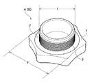
すなわち、中栓A,Bは、図2に示したように、3組の略平行な辺からなる6角形状の操作部1と、この操作部1から突出された略円筒状のネジ部3とにより、全体が略凸状に
形成されている。そして、円筒状のネジ部3の外周域基端側には、パッキン7が介装されている。
That is, as shown in FIG. 2, the inner plugs A and B include a
このような中栓A,Bは、以下のようにして運搬用容器30に取り付けられている。
Such inner plugs A and B are attached to the
すなわち、運搬用容器30の短側壁32には、予め貫通した孔が高さの異なる位置に形成されており、これらの孔の容器内方側からパイプ状の被嵌合部材が挿入され、この被嵌合部材に設けられた内ネジに、容器外方側から中栓A,Bが螺合されることにより、短側壁32に着脱自在に取り付けられている。
That is, holes penetrating in advance are formed in the
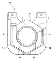
一方、運搬用容器30には、図3に示したような合成樹脂樹脂製の中栓収容ホルダー40が、例えば超音波溶着などにより取り付けられている。図3の中栓収容ホルダー40は、本発明の一実施例を説明するのに好適な参考例を示したものである。中栓収容ホルダー40は、そのホルダー本体20が、平板状の背板部2と、背板部2の左右両端部から上下方向に延出された側板部4,6と、この側板部4,6の下端を閉塞するように、斜め下方に傾斜して配置された傾斜底板部8,10と、これら傾斜底板部8,10の手前側を覆うように、側板部4,6間に跨って配置された規制板12,14とから構成され、これらの
規制板12,14は、背板部2と略平行に配置されることにより、中栓A,Bの脱落を防止する機能を有している。
On the other hand, a synthetic resin resin-made inner
一方、側板部4,6の上下方向の長さは、右側に位置する側板部4の方が、左側に位置する側板部6よりも短い。すなわち、右側板部4の上端部が、左側板部6の上端部よりも低い。
On the other hand, the length of the
これら側板部4,6の上端部には、上方に向うに従って斜め外方に拡開する案内板部16,16が設けられており、同様に、規制板12,14の上端部にも上方に向うに従って図の手前側に拡開する案内板部17,17が設けられている。
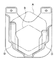
このように、本参考例では、右側板部4の方が左側板部6よりも背が低くされることにより、図4に示したように、内部の収容空間Cに臨む間口の開口幅Hが広くされている。また、特に、右側板部4の上部に案内板部16が設置されることにより、中栓A,Bがここに当接された場合に、下方に滑り易くなっている。
As described above, in the present reference example, the right
ここで、図2あるいは図4に示したように、中栓収容ホルダー40の側板部4,6間の離間距離Eは、中栓Aにおける一対の平行な辺の幅Fよりもやや大きく、規制板12,14の内側の辺同士の離間距離Gは、中栓Aのネジ部3の外径Iよりもやや大きい。そして、規制板12,14の湾曲したコーナ部36の曲率は、円筒状のネジ部3の曲率と略等しくされている。
Here, as shown in FIG. 2 or FIG. 4, the separation distance E between the
本参考例に係る収容ホルダー40は上記のように形成されることにより、中栓A,Bの収容空間Cが内方に画成されている。以下に、中栓収容ホルダーの作用について説明する。
The
今、中栓収容ホルダー40は、図1に示したように大型運搬用容器30の短側壁32などに、例えば、超音波溶着により一体的に取り付けられている。
Now, as shown in FIG. 1, the inner
そして、大型の中栓Aが取り外されると、その中栓Aは収容ホルダー40の収容空間C内に収容され、保管される。
When the large inner plug A is removed, the inner plug A is stored in the storage space C of the
このとき、作業者は、図4に示したように、中栓Aのネジ部3を紙面の手前側にし、その姿勢から矢印Jで示したように、収容空間C内に投入する。ここで、中栓収容ホルダー
40の開口幅Hが大きくされているので、このHの範囲内であれば、どの位置から中栓Aを投入しても収容空間C内に速やかに案内することができる。そして、やや斜め上方向から投入された場合には、中栓Aの下端が右側板部4の案内板部16に当接され、その当接により衝撃が吸収されるとともに、案内板部16を滑動しながら下方に案内する。このとき、中栓Aは、半時計方向への回動力が付与され滑動する。中栓Aが側板部4,6の下端にまで到達すると、今度は傾斜側板部8,10により保持されるので、その位置に停止する。しかも、背板部2と略平行な規制板14,12により前面側が覆われるので、中栓Aの脱落が防止される。このとき、円筒状のネジ部3は、規制板12,14の間に挟まれるとともに、ネジ部3の下端周面がコーナ部36に沿って配置される。また、幅Fを備えた操作部1の一対の平行な辺が、側板部4,6間に配置されるので、左右方向への移動が規制される。
At this time, as shown in FIG. 4, the operator sets the
次に、径の小さい方の中栓Bを中栓収容ホルダー40内に収容する場合について説明する。この場合も、図4に示したように、間口幅Hの範囲内で投入される。そして、小型の中栓Bも大型の中栓Aと同じ位置まで落とし込まれるが、このとき、図6に示したように、円筒状のネジ部3が、規制板12,14のコーナ部36より下方に配置され、内方に膨出された舌片12a,14a内に臨むように配置されるので、左右方向への移動が防止される。よって、小型の中栓Bであっても移動が規制されて収容される。
Next, a case where the inner plug B having the smaller diameter is accommodated in the inner
以上説明したように、本参考例に係る収容ホルダー40を、図1に示したように、大型運搬用容器30に搭載すれば、中栓A,Bのいずれであっても収容することができる。よって、中栓A,Bを運搬用容器30の移動中に紛失してしまうことはない。また、移動中に異音を発生することもない。勿論、整然とした状態でホルダー内に管理されるので、美観的にも良好である。
As described above, if the
以上、本発明を説明するのに好適な参考例について説明したが、以下、本発明の実施例について、図7、図8を参照しながら説明する。
The reference examples suitable for describing the present invention have been described above. Hereinafter , embodiments of the present invention will be described with reference to FIGS.
なお、上記参考例では、側板部4の上部に案内板部16を設け、さらに側板部6の上部にも案内板部16を設けているが、側板部6側の案内板部16は、美観的に設けたものであって、本発明では、特に必要ではない。また、同様に、規制板12、14の上部にも案内板部17、17を設けているが、これらも特に必須のものではない。しかしながら、全体的なデザインを考慮すれば左右対称に設けることが好ましい。
In the above reference example, the
また、上記参考例では、傾斜底板部8,10間が離間して配置されているので、水などが付着した中栓を収容しても、その隙間から外部に排出することができる。
In the above reference example, since the inclined
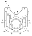
また、上記参考例では、側板部4,6は直線状に形成されているが、図7および図8に示した本発明の一実施例では、これに代え、側板部4,6と、傾斜底板部8,10との会合部に、収容空間C側に突出された段部Dが設けられている。このような段部Dを形成すれば、この段部Dの下部に小型の中栓Bを移動不能に収容し、段部Dの上部に、大型の中栓Aを収容することができる。したがって、段部D以外の部分を参考例と同一の構造とする本実施例では、大型の中栓Aは勿論のこと、特に、小型の中栓Bも両側が確実に保持されるので、小型の中栓Bの移動を一層効果的に防止することができる。
In the above reference example, the
さらに、上記参考例では、中栓A,Bを大型運搬用容器30に超音波溶着により固定しているが、これに代え、例えば、図7に示したように、運搬用容器30にボス34を突設し、このボス34に挿入される孔38を背板部2に設けておけば、ボス34を孔38挿入した後に、熱溶着などで一体化することもできる。このように、ホルダー40の取り付けは、実施例に何ら限定されない。
Furthermore, in the above reference example, the inner plugs A and B are fixed to the
1 操作部
2 背板部
3 ネジ部
4,6 側板部
8,10 傾斜底板部
12,14 規制板
16 案内板部
20 ホルダー本体
30 大型運搬用容器
32 短側壁
40 中栓収容ホルダー
A,B 中栓
C 収容空間
H 開口幅
D 段部
DESCRIPTION OF
Claims (3)
中栓(A)、(B)の収容空間(C)を備えたホルダー本体(20)は、
平板状の背板部(2)と、
この背板部(2)の左右両端部から上下方向に延出された側板部(4)、(6)と、
この側板部(4)、(6)の下端を閉塞するように、前記側板部(4)、(6)から斜め下方にそれぞれ傾斜して配置された傾斜底板部(8)、(10)と、
これら傾斜底板部(8)、(10)と前記側板部(4)、(6)との間に跨って配置され、前記収容空間(C)に収容された前記中栓(A)または(B)の脱落を防止する規制板(12)、(14)と、から構成され、
前記一方の側板部(4)の上端部を、前記他方の側板部(6)の上端部よりも低い位置に設定するとともに、前記側板部(4)、(6)と、前記傾斜底板部(8)、(10)との会合部に、前記収容空間(C)側に突出した段部(D)を設けたこと特徴とする中栓収容ホルダー。 An inner plug formed in a substantially convex shape by a polygonal operation portion (1) having at least a pair of parallel sides and a substantially cylindrical screw portion (3) protruding from the operation portion (1). (A), (B) is an inner stopper storage holder for selectively storing,
The holder body (20) provided with the storage space (C) for the inner plugs (A) and (B)
A flat back plate (2);
Side plate portions (4), (6) extending in the vertical direction from the left and right end portions of the back plate portion (2),
Inclined bottom plate portions (8), (10) disposed obliquely downward from the side plate portions (4), (6) so as to close the lower ends of the side plate portions (4), (6); ,
The inner plug (A) or (B) disposed between the inclined bottom plate portions (8), (10) and the side plate portions (4), (6) and accommodated in the accommodation space (C). ), And the restriction plates (12) and (14) for preventing the dropout
The upper end portion of the one side plate portion (4) is set at a position lower than the upper end portion of the other side plate portion (6) , and the side plate portions (4), (6) and the inclined bottom plate portion ( 8) An internal stopper storage holder characterized in that a step portion (D) protruding toward the storage space (C) is provided at a meeting portion with (10) .
Priority Applications (1)
| Application Number | Priority Date | Filing Date | Title |
|---|---|---|---|
| JP2003270743A JP4339035B2 (en) | 2003-07-03 | 2003-07-03 | Inner stopper holder |
Applications Claiming Priority (1)
| Application Number | Priority Date | Filing Date | Title |
|---|---|---|---|
| JP2003270743A JP4339035B2 (en) | 2003-07-03 | 2003-07-03 | Inner stopper holder |
Publications (2)
| Publication Number | Publication Date |
|---|---|
| JP2005022745A JP2005022745A (en) | 2005-01-27 |
| JP4339035B2 true JP4339035B2 (en) | 2009-10-07 |
Family
ID=34190627
Family Applications (1)
| Application Number | Title | Priority Date | Filing Date |
|---|---|---|---|
| JP2003270743A Expired - Lifetime JP4339035B2 (en) | 2003-07-03 | 2003-07-03 | Inner stopper holder |
Country Status (1)
| Country | Link |
|---|---|
| JP (1) | JP4339035B2 (en) |
-
2003
- 2003-07-03 JP JP2003270743A patent/JP4339035B2/en not_active Expired - Lifetime
Also Published As
| Publication number | Publication date |
|---|---|
| JP2005022745A (en) | 2005-01-27 |
Similar Documents
| Publication | Publication Date | Title |
|---|---|---|
| US7856945B2 (en) | Animal litter box | |
| US7832357B2 (en) | Animal litter box | |
| JP6192468B2 (en) | Animal toilet packaging | |
| USD554302S1 (en) | Large pet food storage container | |
| JP5823284B2 (en) | Partition container | |
| KR101081838B1 (en) | The reagent instrument having good safety | |
| JP4339035B2 (en) | Inner stopper holder | |
| KR20210049667A (en) | Cooler box | |
| JP2007319205A (en) | Tablet dispenser | |
| KR20120084512A (en) | Cutting tool case | |
| JP2020137416A (en) | Pet litter box | |
| TWI681712B (en) | Animal toilet | |
| JP6219235B2 (en) | Granule storage container | |
| US20070175777A1 (en) | Cartridge accommodation case | |
| JP4381314B2 (en) | Writing board | |
| JP2009051515A (en) | Impact resistant container | |
| US6629870B2 (en) | Bubble blower | |
| JP2007204083A (en) | Cartridge storage case | |
| JP3208152U (en) | Carry Bag | |
| JP4784986B2 (en) | Cap with lid plate that automatically opens | |
| JP7086478B2 (en) | Granule storage container | |
| JP4190719B2 (en) | Large container reinforcement | |
| JP2011077332A (en) | Terminal box | |
| KR20170003128U (en) | Transportation equipment buckets | |
| JP7094530B2 (en) | Water dispenser for pets |
Legal Events
| Date | Code | Title | Description |
|---|---|---|---|
| A621 | Written request for application examination |
Free format text: JAPANESE INTERMEDIATE CODE: A621 Effective date: 20050927 |
|
| A131 | Notification of reasons for refusal |
Free format text: JAPANESE INTERMEDIATE CODE: A131 Effective date: 20090203 |
|
| A521 | Request for written amendment filed |
Free format text: JAPANESE INTERMEDIATE CODE: A523 Effective date: 20090213 |
|
| TRDD | Decision of grant or rejection written | ||
| A01 | Written decision to grant a patent or to grant a registration (utility model) |
Free format text: JAPANESE INTERMEDIATE CODE: A01 Effective date: 20090609 |
|
| A01 | Written decision to grant a patent or to grant a registration (utility model) |
Free format text: JAPANESE INTERMEDIATE CODE: A01 |
|
| A61 | First payment of annual fees (during grant procedure) |
Free format text: JAPANESE INTERMEDIATE CODE: A61 Effective date: 20090701 |
|
| R150 | Certificate of patent or registration of utility model |
Ref document number: 4339035 Country of ref document: JP Free format text: JAPANESE INTERMEDIATE CODE: R150 Free format text: JAPANESE INTERMEDIATE CODE: R150 |
|
| FPAY | Renewal fee payment (event date is renewal date of database) |
Free format text: PAYMENT UNTIL: 20120710 Year of fee payment: 3 |
|
| FPAY | Renewal fee payment (event date is renewal date of database) |
Free format text: PAYMENT UNTIL: 20150710 Year of fee payment: 6 |
|
| R250 | Receipt of annual fees |
Free format text: JAPANESE INTERMEDIATE CODE: R250 |
|
| R250 | Receipt of annual fees |
Free format text: JAPANESE INTERMEDIATE CODE: R250 |
|
| R250 | Receipt of annual fees |
Free format text: JAPANESE INTERMEDIATE CODE: R250 |
|
| R250 | Receipt of annual fees |
Free format text: JAPANESE INTERMEDIATE CODE: R250 |
|
| EXPY | Cancellation because of completion of term |