JP4338188B2 - Image data reduction apparatus and method, program, storage medium, and imaging apparatus - Google Patents
Image data reduction apparatus and method, program, storage medium, and imaging apparatus Download PDFInfo
- Publication number
- JP4338188B2 JP4338188B2 JP2003361134A JP2003361134A JP4338188B2 JP 4338188 B2 JP4338188 B2 JP 4338188B2 JP 2003361134 A JP2003361134 A JP 2003361134A JP 2003361134 A JP2003361134 A JP 2003361134A JP 4338188 B2 JP4338188 B2 JP 4338188B2
- Authority
- JP
- Japan
- Prior art keywords
- color
- image data
- pixels
- line
- horizontal direction
- Prior art date
- Legal status (The legal status is an assumption and is not a legal conclusion. Google has not performed a legal analysis and makes no representation as to the accuracy of the status listed.)
- Expired - Fee Related
Links
Images


Classifications
-
- H—ELECTRICITY
- H04—ELECTRIC COMMUNICATION TECHNIQUE
- H04N—PICTORIAL COMMUNICATION, e.g. TELEVISION
- H04N1/00—Scanning, transmission or reproduction of documents or the like, e.g. facsimile transmission; Details thereof
- H04N1/387—Composing, repositioning or otherwise geometrically modifying originals
- H04N1/393—Enlarging or reducing
- H04N1/3935—Enlarging or reducing with modification of image resolution, i.e. determining the values of picture elements at new relative positions
Description
本発明は撮像素子から読み出される画像信号の画素数の減少処理技術に関するものである。 The present invention relates to a technique for reducing the number of pixels of an image signal read from an image sensor.
デジタルスティルカメラの中には、撮像素子の有効画素数にほぼ等しい記録画素数での撮影の他に、有効画素数よりも少ない記録画素数での撮影ができる機能を持つ製品も現れている。一方で、撮像素子の画素数が年々増加の傾向を示している中、ストレスを撮影者に感じさせず快適な撮影を行うためには、デジタルカメラを構成する各部分の全体の高速化に加えて、上記のような有効画素数よりも少ない記録画素数での撮影時には画像処理を施す信号のデータ量を減らす工夫も求められている。
このような要請の中、特開平11−308560号公報では、元画像のベイヤー配列のデータに減少処理を施し、少ない画素数のベイヤー配列のデータを得ることによって高速に画像処理・記録を行なうことが提案されている。しかしながら、上記公報に記載のデータの減少処理の方法では、減少処理後のベイヤー配列のデータの画素信号の重心位置が偏ってしまい、詳しい説明は割愛するがその後の信号処理の結果で得られる画像が劣化してしまうという問題があった。 In such a request, Japanese Patent Application Laid-Open No. 11-308560 discloses that the Bayer array data of the original image is subjected to a reduction process, and Bayer array data having a small number of pixels is obtained to perform image processing / recording at high speed. Has been proposed. However, in the data reduction processing method described in the above publication, the barycentric position of the pixel signals of the Bayer array data after the reduction processing is biased, and a detailed description is omitted, but the image obtained as a result of the subsequent signal processing There was a problem that would deteriorate.
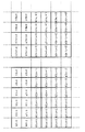
画像が劣化する従来の1/4減少処理の例を図6及び図7に示す。図6は減少処理前のG、R、B、gの4色のベイヤー配列のデータの平面的な位置を示した図であり、図7は縦横共1/2減少処理をした場合のデータの平面的な重心位置を示した図である。 An example of a conventional 1/4 reduction process in which an image deteriorates is shown in FIGS. FIG. 6 is a diagram showing the planar position of the four-color Bayer array data of G, R, B, and g before the reduction process, and FIG. It is the figure which showed the plane gravity center position.
ここに、従来の減少処理の変換式を示す。 Here, the conversion formula of the conventional reduction process is shown.
G’1=(G1+G2+G6+G7)/4
R’1=(R1+R2+R6+R7)/4
B’1=(B1+B2+B6+B7)/4
g’1=(g1+g2+g6+g7)/4
図7に示すように、減少処理後のデータの各画素の重心のピッチは一定にならないことが判る。
G′1 = (G1 + G2 + G6 + G7) / 4
R′1 = (R1 + R2 + R6 + R7) / 4
B′1 = (B1 + B2 + B6 + B7) / 4
g′1 = (g1 + g2 + g6 + g7) / 4
As shown in FIG. 7, it can be seen that the pitch of the center of gravity of each pixel of the data after the reduction process is not constant.
従って、本発明は上述した課題に鑑みてなされたものであり、その目的は、撮像素子がもともと持っている画素数のデータを、それよりも少ない画素数のデータに変換する場合に、画像の劣化を極力防止できるようにすることである。 Therefore, the present invention has been made in view of the above-described problems, and the object of the present invention is to convert image data when the image sensor originally has the number of pixels into data having a smaller number of pixels. It is to be able to prevent deterioration as much as possible.
上述した課題を解決し、目的を達成するために、本発明に係わる画像データ減少装置は、第1色の画素と第2色の画素が横方向または縦方向に1画素毎に交互に配置された画像データの画素数を、前記横方向または前記縦方向において減少処理する画像データ減少装置であって、前記横方向または前記縦方向の1ライン上で前記第2色の画素を挟んで連続する前記第1色の2画素の重心に位置する画素に対応する画像データを前記1ラインにおける前記第1色の画像データとして出力し、前記横方向または前記縦方向の前記1ライン上で前記第1色の画素を挟んで連続する前記第2色の3画素の重心に位置する画素に対応する画像データを前記1ラインにおける前記第2色の画像データとして出力することにより、前記第1色及び前記第2色の各画素の重心が前記横方向または前記縦方向の前記1ライン上で等間隔になるように、前記横方向または前記縦方向の前記1ラインの画素数を2分の1に減少させる減少処理手段を有することを特徴とする。 In order to solve the above-described problems and achieve the object, an image data reduction device according to the present invention includes a first color pixel and a second color pixel arranged alternately in the horizontal direction or the vertical direction for each pixel. An image data reduction device that reduces the number of pixels of image data in the horizontal direction or the vertical direction, and is continuous on one line in the horizontal direction or the vertical direction with the pixels of the second color interposed therebetween. Image data corresponding to a pixel located at the center of gravity of the two pixels of the first color is output as the image data of the first color in the one line, and the first data on the one line in the horizontal direction or the vertical direction. By outputting the image data corresponding to the pixel located at the center of gravity of the three pixels of the second color that are continuous across the pixel of the color as the image data of the second color in the one line, the first color and the Second color Reduction processing means for reducing the number of pixels of the one line in the horizontal direction or the vertical direction by half so that the centers of gravity of the pixels are equally spaced on the one line in the horizontal direction or the vertical direction It is characterized by having .
また、本発明に係わる撮像装置は、上記の画像データ減少装置と、該画像データ減少装置から出力された画像データを記録する記録手段とを有することを特徴とする。 The imaging apparatus according to the present invention is characterized in that chromatic image data reduction apparatus described above, and a recording means for recording images data outputted from the image data reduction unit.
また、本発明に係わる画像データ減少方法は、第1色の画素と第2色の画素が横方向または縦方向に1画素毎に交互に配置された画像データの画素数を、前記横方向または前記縦方向において減少処理する画像データ減少方法であって、前記横方向または前記縦方向の1ライン上で前記第2色の画素を挟んで連続する前記第1色の2画素の重心に位置する画素に対応する画像データを前記1ラインにおける前記第1色の画像データとして出力し、前記横方向または前記縦方向の前記1ライン上で前記第1色の画素を挟んで連続する前記第2色の3画素の重心に位置する画素に対応する画像データを前記1ラインにおける前記第2色の画像データとして出力することにより、前記第1色及び前記第2色の各画素の重心が前記横方向または前記縦方向の前記1ライン上で等間隔になるように、前記横方向または前記縦方向の前記1ラインの画素数を2分の1に減少させる減少処理工程を有することを特徴とする。 In the image data reduction method according to the present invention, the number of pixels of the image data in which the pixels of the first color and the pixels of the second color are alternately arranged in the horizontal direction or the vertical direction for each pixel is determined in the horizontal direction or An image data reduction method for performing reduction processing in the vertical direction, wherein the image data reduction method is located at the center of gravity of two pixels of the first color that are continuous across the pixel of the second color on one line in the horizontal direction or the vertical direction. The image data corresponding to the pixel is output as the image data of the first color in the one line, and the second color that is continuous with the pixel of the first color on the one line in the horizontal direction or the vertical direction. By outputting image data corresponding to a pixel located at the center of gravity of the three pixels as the second color image data in the one line, the center of gravity of each pixel of the first color and the second color is in the horizontal direction. Or the vertical Said to be equally spaced on a line of direction, characterized by having a reduced processing step of reducing the number of pixels the transverse direction or the longitudinal direction of the one line to 1/2.
また、本発明に係わるプログラムは、上記の画像データ減少方法をコンピュータに実行させることを特徴とする。 A program according to the present invention causes a computer to execute the above image data reduction method.
また、本発明に係わる記憶媒体は、上記のプログラムをコンピュータ読み取り可能に記憶したことを特徴とする。 A storage medium according to the present invention stores the above-mentioned program so as to be readable by a computer.
以上のように構成される本願発明によれば、縦又は横又は縦横両方向の減少処理を行うことにより、その後の処理において扱われるデータ量を減らし、且つ、高画質の最終画像を得ることが出来る。 According to the present invention configured as described above, the amount of data handled in the subsequent processing can be reduced and a high-quality final image can be obtained by performing reduction processing in the vertical, horizontal, or both vertical and horizontal directions. .
以下、本発明の好適な実施形態について、添付図面を参照して詳細に説明する。 DESCRIPTION OF EXEMPLARY EMBODIMENTS Hereinafter, preferred embodiments of the invention will be described in detail with reference to the accompanying drawings.
(第1の実施形態)
図1及び図2は、本発明の画像データ減少方法の第1の実施形態を説明するための図である。本実施形態は、縦横方向ともに画素数を1/2減少する場合の例である。
(First embodiment)
1 and 2 are diagrams for explaining a first embodiment of an image data reduction method according to the present invention. The present embodiment is an example in which the number of pixels is reduced by 1/2 in both the vertical and horizontal directions.
図1は減少処理前のデータの平面上の配置を示したもので、G,R,B,gの4色によるベイヤー配列になっている。尚、同図中、m、nは1以上の整数である。 FIG. 1 shows the arrangement of data before reduction processing on a plane, and is a Bayer array with four colors G, R, B, and g. In the figure, m and n are integers of 1 or more.
図2は減少処理後のデータの平面上の配置を示したもので、図1と同様にG,R,B,gの4色によるベイヤー配列になっている。 FIG. 2 shows the arrangement of the data after the reduction processing on the plane, and it is a Bayer array with four colors G, R, B, and g as in FIG.
ここに、本実施形態の減少処理の変換式の例を示す。 Here, an example of the conversion formula of the reduction process of this embodiment is shown.
G'(m,n) = (G(2m-1,n)+G(2m,n)+G(2m-1,n+1)+G(2m,n+1))/4 …(1−1)
R'(m,n) = (R(2m,n)+R(2m,n+1))/2 …(1−2)
B'(m,n) = (B(2m-1,n+1)+B(2m,n+1))/2 …(1−3)
g'(m,n) = (g(2m,n)+g(2m-1,n+1)+g(2m+1,n+1)+g(2m,n+2)+4×g(2m,n+1))/8
…(1−4)
図2に示すように減少処理後のデータの重心ピッチが等間隔になるように上記の式(1−1)から式(1−4)を設定している。
G '(m, n) = (G (2m-1, n) + G (2m, n) + G (2m-1, n + 1) + G (2m, n + 1)) / 4 (1) -1)
R ′ (m, n) = (R (2m, n) + R (2m, n + 1)) / 2 (1-2)
B '(m, n) = (B (2m-1, n + 1) + B (2m, n + 1)) / 2 (1-3)
g '(m, n) = (g (2m, n) + g (2m-1, n + 1) + g (2m + 1, n + 1) + g (2m, n + 2) + 4 × g (2m, n + 1)) / 8
... (1-4)
As shown in FIG. 2, the above equations (1-1) to (1-4) are set so that the barycentric pitches of the data after the reduction processing are equally spaced.
上記の式(1−1)から式(1−4)の他にも本発明の趣旨である減少処理後のデータの重心ピッチが等間隔であることを実現する変換式は考えられ、それらによっても本発明が実現できることは言うまでも無い。その例として、以下に、上記式(1−2)、(1−3)に代わる式(1−2’)、式(1−3’)を示す。 In addition to the above formulas (1-1) to (1-4), conversion formulas that realize that the centroid pitches of the data after reduction processing, which is the gist of the present invention, are equally spaced are conceivable. Needless to say, the present invention can be realized. As an example, equations (1-2 ') and (1-3') in place of the equations (1-2) and (1-3) are shown below.
R'(m,n) = (R(2m,n-1)+2×R(2m,n)+2×R(2m,n+1)+R(2m,n+2))/6 …(1−2’)
B'(m,n) = (B(2m-2,n+1)+2×B(2m-1,n+1)+2×B(2m,n+1)+B(2m+1,n+1))/6
…(1−3’)
また、G色とg色を同一として扱った次のような変換式も本発明に適用可能である。
R '(m, n) = (R (2m, n-1) + 2 × R (2m, n) + 2 × R (2m, n + 1) + R (2m, n + 2)) / 6… (1-2 ')
B '(m, n) = (B (2m-2, n + 1) + 2 × B (2m-1, n + 1) + 2 × B (2m, n + 1) + B (2m + 1, n + 1)) / 6
... (1-3 ')
Further, the following conversion formula that treats the G color and the g color as the same can also be applied to the present invention.
G'(m,n) = (G(2m-1,n)+G(2m,n)+G(2m-1,n+1)+G(2m,n+1)+4×g(2m-1,n))/8
…(1−1’)
g'(m,n) = (G(2m,n+1)+G(2m+1,n+1)+G(2m,n+2)+G(2m+1,n+2)+4×g(2m,n+1))/8
…(1−4’)
(第2の実施形態)
図3及び図4は、本発明の画像データ減少方法の第2の実施形態を説明するための図である。第2の実施形態は、横方向のみ画素数を1/2減少した場合の例である。
G '(m, n) = (G (2m-1, n) + G (2m, n) + G (2m-1, n + 1) + G (2m, n + 1) + 4 × g (2m -1, n)) / 8
... (1-1 ')
g '(m, n) = (G (2m, n + 1) + G (2m + 1, n + 1) + G (2m, n + 2) + G (2m + 1, n + 2) +4 × g (2m, n + 1)) / 8
... (1-4 ')
(Second Embodiment)
3 and 4 are diagrams for explaining a second embodiment of the image data reduction method of the present invention. The second embodiment is an example in which the number of pixels is reduced by ½ only in the horizontal direction.
図3は減少処理前のデータの平面上の配置を示したもので、G,R,B,gの4色によるベイヤー配列になっている。尚、同図中、m、nは1以上の整数である。 FIG. 3 shows the arrangement of the data before the reduction process on the plane, and has a Bayer arrangement with four colors G, R, B, and g. In the figure, m and n are integers of 1 or more.
図4は減少処理後のデータの平面上の配置を示したもので、図3と同様にG,R,B,gの4色によるベイヤー配列になっている。 FIG. 4 shows the arrangement on the plane of the data after the reduction process, and it is a Bayer array with four colors G, R, B, and g, as in FIG.
ここに、本実施形態の減少処理の変換式例を示す。 Here, a conversion formula example of the reduction process of the present embodiment is shown.
G'(m,n) = (G(2m-1,n)+G(2m,n))/2 …(2−1)
R'(m,n) = (R(2m-1,n)+2×R(2m,n)+R(2m+1,n))/4 …(2−2)
B'(m,n) = (B(2m-1,n)+B(2m,n))/2 …(2−3)
g'(m,n) = (g(2m-1,n)+2×g(2m,n)+g(2m+1,n))/4 …(2−4)
図4に示すように減少処理後の横方向のデータの重心ピッチが等間隔になるように式(2−1)から式(2−4)を設定している。
G ′ (m, n) = (G (2m-1, n) + G (2m, n)) / 2 (2-1)
R ′ (m, n) = (R (2m-1, n) + 2 × R (2m, n) + R (2m + 1, n)) / 4 (2-2)
B '(m, n) = (B (2m-1, n) + B (2m, n)) / 2 (2-3)
g '(m, n) = (g (2m-1, n) + 2 × g (2m, n) + g (2m + 1, n)) / 4 (2-4)
As shown in FIG. 4, Equations (2-1) to (2-4) are set so that the barycentric pitches of the lateral data after the reduction processing are equally spaced.
上記の式(2−1)から式(2−4)の他にも本発明の趣旨である減少処理後のデータの重心ピッチが等間隔であることを実現する変換式は考えられ、それらによっても本発明が実現できることは言うまでも無い。その例として、ここに、上記の式(2−2)、(2−4)に代わる式(2−2’)、式(2−4’)を示す。 In addition to the above equations (2-1) to (2-4), conversion equations that realize that the centroid pitches of the data after the reduction processing, which is the gist of the present invention, are equally spaced are conceivable. Needless to say, the present invention can be realized. As an example, equations (2-2 ') and (2-4') in place of the equations (2-2) and (2-4) are shown here.
R'(m,n) = R(2m,n) …(2−2’)
g'(m,n) = g(2m,n) …(2−4’)
また、本実施形態では横方向のみの減少処理について述べたが、縦方向のみの減少処理も同様に構成できることは言うまでも無い。
R ′ (m, n) = R (2m, n) (2-2 ′)
g ′ (m, n) = g (2m, n) (2-4 ′)
Further, although the reduction process only in the horizontal direction has been described in the present embodiment, it goes without saying that the reduction process only in the vertical direction can be configured similarly.
(第3の実施形態)
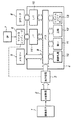
図5は本発明をデジタルスティルカメラに適用した場合の実施形態を説明するためのブロック図である。
(Third embodiment)
FIG. 5 is a block diagram for explaining an embodiment when the present invention is applied to a digital still camera.
図5において、1はGRの繰り返しからなる列、及び、BGの繰り返しからなる列が交互に配置されたいわゆるベイヤー配列のカラー撮像素子、2はAD変換器、3は減少処理回路、4はデジタル信号処理回路、5はメモリー、6はマイクロコンピュータ、7は操作スイッチ、8はコンパクトフラッシュ(登録商標)カードなどの記録媒体である。デジタル信号処理回路4の内部は、バス9、画像処理部10、縮小回路11、圧縮回路12、システムコントローラー13、マイクロコンピュータインターフェース14、記録媒体インターフェース15などから構成されている。また、操作スイッチ7には撮影のためのレリーズボタン及び記録画素数を選択するための画素数選択ボタン等が含まれている。
In FIG. 5, 1 is a so-called Bayer array color image pickup device in which rows of repeating GR and rows of repeating BG are alternately arranged, 2 is an AD converter, 3 is a reduction processing circuit, and 4 is digital. A signal processing circuit, 5 is a memory, 6 is a microcomputer, 7 is an operation switch, and 8 is a recording medium such as a compact flash (registered trademark) card. The digital signal processing circuit 4 includes a
次に、順を追って撮影から記録までの動作の概略を説明する。 Next, an outline of operations from shooting to recording will be described in order.
マイクロコンピュータ6は操作スイッチ7の中のレリーズボタンの操作を認識すると不図示の撮像光学系を通して撮像素子1に被写体像を結像させる。撮像素子1からは適切な露光期間の後、列ごとにアナログ画像データが読み出される。このアナログ画像データはAD変換器2にてアナログからデジタルへ変換され第1のデジタル画像データとなり減少処理回路3へ入る。
When the
減少処理回路3へは、マイクロコンピュータ6から操作スイッチ7の中の画素数選択ボタンによる画素数選択情報が渡されており、減少処理が不必要な場合にはそのままの第1のデジタル画像データがデジタル信号処理回路4に送られ、減少処理が必要な場合には減少処理をしたデジタル画像データが第2のデジタル画像データとしてデジタル信号処理回路4に送られる。
To the
デジタル信号処理回路4では、マイクロコンピュータ6からマイクロコンピュータインターフェース14及びバス9を通じてシステムコントローラ13をはじめ各部に順次制御信号の設定がなされる。第2のデジタル画像データは画像処理部10で所定の画像処理が行われ、必要に応じて縮小回路11で縮小され、圧縮回路12で例えばJPEG圧縮され、適当なファイルフォーマットの形で記録媒体インターフェース15を通じて記録媒体8へ記録される。
In the digital signal processing circuit 4, control signals are sequentially set from the
第2のデジタル画像信号は、上記の一連の処理の中でその形を変えながら、デジタル信号処理回路4を構成する各部及びメモリー5間をバス9を通じてやり取りされる。第2のデジタル信号が減少処理回路3で画素数減少されたものである場合には、減少処理されていない場合に比べてデジタル信号処理回路4の各部の処理量及びバス9のトラフィックが減るので上記の一連の処理時間を減らすことが可能である。
The second digital image signal is exchanged through the
減少処理回路3は、減少処理後のデータの重心ピッチが等間隔になるように前述の第1及び第2の実施形態に示したような変換式に則って構成されている。このため、従来に比べて画像劣化の少ない最終的な画像を得ることが出来る。
The
また、縮小回路11は、減少処理回路3が第2の実施形態のような横方向のみ又は縦方向のみの減少処理を行なう場合において、減少処理がなされていない方向の縮小を行い最終的な画像を作るためにある。
Further, when the
なお、上記の第1、第2の実施形態においては、信号の平面的配置が所謂ベイヤー配列の場合についてのみ説明したが、他の種類の配列においても本発明を適用することは可能である。 In the first and second embodiments described above, only the case where the planar arrangement of signals is a so-called Bayer arrangement has been described. However, the present invention can be applied to other types of arrangement.
(他の実施形態)
また、各実施形態の目的は、前述した実施形態の機能を実現するソフトウェアのプログラムコードを記録した記憶媒体(または記録媒体)を、システムあるいは装置に供給し、そのシステムあるいは装置のコンピュータ(またはCPUやMPU)が記憶媒体に格納されたプログラムコードを読み出し実行することによっても、達成されることは言うまでもない。この場合、記憶媒体から読み出されたプログラムコード自体が前述した実施形態の機能を実現することになり、そのプログラムコードを記憶した記憶媒体は本発明を構成することになる。また、コンピュータが読み出したプログラムコードを実行することにより、前述した実施形態の機能が実現されるだけでなく、そのプログラムコードの指示に基づき、コンピュータ上で稼働しているオペレーティングシステム(OS)などが実際の処理の一部または全部を行い、その処理によって前述した実施形態の機能が実現される場合も含まれることは言うまでもない。
(Other embodiments)
In addition, an object of each embodiment is to supply a storage medium (or recording medium) on which a program code of software that realizes the functions of the above-described embodiments is recorded to a system or apparatus, and a computer (or CPU) of the system or apparatus Needless to say, this can also be achieved by reading and executing the program code stored in the storage medium. In this case, the program code itself read from the storage medium realizes the functions of the above-described embodiments, and the storage medium storing the program code constitutes the present invention. Further, by executing the program code read by the computer, not only the functions of the above-described embodiments are realized, but also an operating system (OS) running on the computer based on the instruction of the program code. It goes without saying that a case where the function of the above-described embodiment is realized by performing part or all of the actual processing and the processing is included.
さらに、記憶媒体から読み出されたプログラムコードが、コンピュータに挿入された機能拡張カードやコンピュータに接続された機能拡張ユニットに備わるメモリに書込まれた後、そのプログラムコードの指示に基づき、その機能拡張カードや機能拡張ユニットに備わるCPUなどが実際の処理の一部または全部を行い、その処理によって前述した実施形態の機能が実現される場合も含まれることは言うまでもない。 Furthermore, after the program code read from the storage medium is written into a memory provided in a function expansion card inserted into the computer or a function expansion unit connected to the computer, the function is determined based on the instruction of the program code. It goes without saying that the CPU or the like provided in the expansion card or the function expansion unit performs part or all of the actual processing and the functions of the above-described embodiments are realized by the processing.
1 カラー撮像素子
2 AD変換器
3 減少処理回路
4 デジタル信号処理回路
5 メモリー
6 マイクロコンピュータ
7 操作スイッチ
8 記録媒体
DESCRIPTION OF
Claims (5)
前記横方向または前記縦方向の1ライン上で前記第2色の画素を挟んで連続する前記第1色の2画素の重心に位置する画素に対応する画像データを前記1ラインにおける前記第1色の画像データとして出力し、前記横方向または前記縦方向の前記1ライン上で前記第1色の画素を挟んで連続する前記第2色の3画素の重心に位置する画素に対応する画像データを前記1ラインにおける前記第2色の画像データとして出力することにより、前記第1色及び前記第2色の各画素の重心が前記横方向または前記縦方向の前記1ライン上で等間隔になるように、前記横方向または前記縦方向の前記1ラインの画素数を2分の1に減少させる減少処理手段を有することを特徴とする画像データ減少装置。 An image data reduction device that reduces the number of pixels of image data in which the pixels of the first color and the pixels of the second color are alternately arranged in the horizontal direction or the vertical direction for each pixel in the horizontal direction or the vertical direction. There,
Image data corresponding to a pixel located at the center of gravity of two pixels of the first color that are continuous across the pixel of the second color on one line in the horizontal direction or the vertical direction is the first color in the one line. Image data corresponding to the pixel located at the center of gravity of the three pixels of the second color that are continuous across the first color pixel on the one line in the horizontal direction or the vertical direction. By outputting the image data of the second color in the one line, the centers of gravity of the pixels of the first color and the second color are equally spaced on the one line in the horizontal direction or the vertical direction. The image data reduction device further comprises a reduction processing means for reducing the number of pixels of the one line in the horizontal direction or the vertical direction by half .
該画像データ減少装置から出力された画像データを記録する記録手段とを有することを特徴とする撮像装置。 The image data reduction device according to claim 1;
Imaging apparatus characterized by chromatic and recording means for recording images data outputted from the image data reduction unit.
前記横方向または前記縦方向の1ライン上で前記第2色の画素を挟んで連続する前記第1色の2画素の重心に位置する画素に対応する画像データを前記1ラインにおける前記第1色の画像データとして出力し、前記横方向または前記縦方向の前記1ライン上で前記第1色の画素を挟んで連続する前記第2色の3画素の重心に位置する画素に対応する画像データを前記1ラインにおける前記第2色の画像データとして出力することにより、前記第1色及び前記第2色の各画素の重心が前記横方向または前記縦方向の前記1ライン上で等間隔になるように、前記横方向または前記縦方向の前記1ラインの画素数を2分の1に減少させる減少処理工程を有することを特徴とする画像データ減少方法。 An image data reduction method for reducing the number of pixels of image data in which the first color pixels and the second color pixels are alternately arranged in the horizontal direction or the vertical direction for each pixel in the horizontal direction or the vertical direction. There,
Image data corresponding to a pixel located at the center of gravity of two pixels of the first color that are continuous across the pixel of the second color on one line in the horizontal direction or the vertical direction is the first color in the one line. Image data corresponding to the pixel located at the center of gravity of the three pixels of the second color that are continuous across the first color pixel on the one line in the horizontal direction or the vertical direction. By outputting the image data of the second color in the one line, the centers of gravity of the pixels of the first color and the second color are equally spaced on the one line in the horizontal direction or the vertical direction. And a reduction processing step of reducing the number of pixels of the one line in the horizontal direction or the vertical direction by half .
Priority Applications (3)
| Application Number | Priority Date | Filing Date | Title |
|---|---|---|---|
| JP2003361134A JP4338188B2 (en) | 2003-10-21 | 2003-10-21 | Image data reduction apparatus and method, program, storage medium, and imaging apparatus |
| US10/969,451 US7907182B2 (en) | 2003-10-21 | 2004-10-20 | Image data reduction apparatus and method, program, storage medium, and image sensing apparatus |
| EP04256480.7A EP1526710B1 (en) | 2003-10-21 | 2004-10-20 | Image data reduction apparatus and method, program, storage medium, and image sensing apparatus |
Applications Claiming Priority (1)
| Application Number | Priority Date | Filing Date | Title |
|---|---|---|---|
| JP2003361134A JP4338188B2 (en) | 2003-10-21 | 2003-10-21 | Image data reduction apparatus and method, program, storage medium, and imaging apparatus |
Publications (3)
| Publication Number | Publication Date |
|---|---|
| JP2005130047A JP2005130047A (en) | 2005-05-19 |
| JP2005130047A5 JP2005130047A5 (en) | 2006-12-07 |
| JP4338188B2 true JP4338188B2 (en) | 2009-10-07 |
Family
ID=34386487
Family Applications (1)
| Application Number | Title | Priority Date | Filing Date |
|---|---|---|---|
| JP2003361134A Expired - Fee Related JP4338188B2 (en) | 2003-10-21 | 2003-10-21 | Image data reduction apparatus and method, program, storage medium, and imaging apparatus |
Country Status (3)
| Country | Link |
|---|---|
| US (1) | US7907182B2 (en) |
| EP (1) | EP1526710B1 (en) |
| JP (1) | JP4338188B2 (en) |
Families Citing this family (1)
| Publication number | Priority date | Publication date | Assignee | Title |
|---|---|---|---|---|
| KR101086501B1 (en) * | 2008-11-26 | 2011-11-25 | 주식회사 하이닉스반도체 | Image data processing method, image sensor, and integrated circuit |
Family Cites Families (11)
| Publication number | Priority date | Publication date | Assignee | Title |
|---|---|---|---|---|
| US5828406A (en) * | 1994-12-30 | 1998-10-27 | Eastman Kodak Company | Electronic camera having a processor for mapping image pixel signals into color display pixels |
| US6348929B1 (en) * | 1998-01-16 | 2002-02-19 | Intel Corporation | Scaling algorithm and architecture for integer scaling in video |
| JP4140077B2 (en) * | 1998-02-18 | 2008-08-27 | ソニー株式会社 | Solid-state image sensor driving method, solid-state image sensor, and camera |
| JP3858447B2 (en) * | 1998-04-23 | 2006-12-13 | カシオ計算機株式会社 | Electronic camera device |
| US6320593B1 (en) * | 1999-04-20 | 2001-11-20 | Agilent Technologies, Inc. | Method of fast bi-cubic interpolation of image information |
| US7158178B1 (en) * | 1999-12-14 | 2007-01-02 | Intel Corporation | Method of converting a sub-sampled color image |
| JP4518616B2 (en) * | 2000-04-13 | 2010-08-04 | ソニー株式会社 | Solid-state imaging device, driving method thereof, and camera system |
| JP2002112047A (en) | 2000-09-29 | 2002-04-12 | Fuji Xerox Co Ltd | Color image formation device and method therefor |
| JP3905708B2 (en) * | 2001-01-26 | 2007-04-18 | ペンタックス株式会社 | Image interpolation device |
| JP4658401B2 (en) | 2001-07-27 | 2011-03-23 | オリンパス株式会社 | Imaging device |
| JP2004147092A (en) * | 2002-10-24 | 2004-05-20 | Canon Inc | Signal processing device, imaging device, and control method |
-
2003
- 2003-10-21 JP JP2003361134A patent/JP4338188B2/en not_active Expired - Fee Related
-
2004
- 2004-10-20 US US10/969,451 patent/US7907182B2/en not_active Expired - Fee Related
- 2004-10-20 EP EP04256480.7A patent/EP1526710B1/en not_active Not-in-force
Also Published As
| Publication number | Publication date |
|---|---|
| EP1526710A2 (en) | 2005-04-27 |
| US7907182B2 (en) | 2011-03-15 |
| US20050083415A1 (en) | 2005-04-21 |
| EP1526710B1 (en) | 2018-09-19 |
| EP1526710A3 (en) | 2006-06-07 |
| JP2005130047A (en) | 2005-05-19 |
Similar Documents
| Publication | Publication Date | Title |
|---|---|---|
| US9560256B2 (en) | Image capture apparatus and image capture method in which an image is processed by a plurality of image processing devices | |
| JP4160883B2 (en) | Image recording apparatus and image recording method | |
| US8248505B2 (en) | Imaging device for adding pixel signals having different timing | |
| JP2015053644A (en) | Imaging device | |
| US7038719B2 (en) | Image sensing apparatus, image processing method, recording medium, and program | |
| JP4115220B2 (en) | Imaging device | |
| JP3902525B2 (en) | Image signal processing device | |
| JP4579613B2 (en) | Image processing apparatus and method, and imaging apparatus | |
| JP5033711B2 (en) | Imaging device and driving method of imaging device | |
| JP2005006061A (en) | Image processor | |
| JP4338188B2 (en) | Image data reduction apparatus and method, program, storage medium, and imaging apparatus | |
| JP2004147092A (en) | Signal processing device, imaging device, and control method | |
| JP4284282B2 (en) | Imaging apparatus and solid-state imaging device | |
| JP2010028758A (en) | Image processing apparatus and method, program, and imaging apparatus | |
| WO2020170729A1 (en) | Image-capturing element, image-capturing device, image-capturing element operation method, and program | |
| US20070196100A1 (en) | Lens unit and digital camera | |
| JP4102055B2 (en) | Data transfer method | |
| JP4229234B2 (en) | Digital camera | |
| JP4310177B2 (en) | Imaging apparatus and imaging method | |
| JP4271011B2 (en) | Imaging processing device | |
| JP2008078794A (en) | Image sensor driver | |
| JP2008199349A (en) | Imaging apparatus capable of sequence conversion of image data | |
| KR20090071321A (en) | Imaging apparatus, imaging method and storing medium having computer program to perform the same | |
| JP2007243819A (en) | Image processing apparatus | |
| JP2011191996A (en) | Image processor and image processing program |
Legal Events
| Date | Code | Title | Description |
|---|---|---|---|
| A521 | Request for written amendment filed |
Free format text: JAPANESE INTERMEDIATE CODE: A523 Effective date: 20061019 |
|
| A621 | Written request for application examination |
Free format text: JAPANESE INTERMEDIATE CODE: A621 Effective date: 20061019 |
|
| A131 | Notification of reasons for refusal |
Free format text: JAPANESE INTERMEDIATE CODE: A131 Effective date: 20090410 |
|
| A521 | Request for written amendment filed |
Free format text: JAPANESE INTERMEDIATE CODE: A523 Effective date: 20090528 |
|
| TRDD | Decision of grant or rejection written | ||
| A01 | Written decision to grant a patent or to grant a registration (utility model) |
Free format text: JAPANESE INTERMEDIATE CODE: A01 Effective date: 20090626 |
|
| A01 | Written decision to grant a patent or to grant a registration (utility model) |
Free format text: JAPANESE INTERMEDIATE CODE: A01 |
|
| A61 | First payment of annual fees (during grant procedure) |
Free format text: JAPANESE INTERMEDIATE CODE: A61 Effective date: 20090629 |
|
| R150 | Certificate of patent or registration of utility model |
Ref document number: 4338188 Country of ref document: JP Free format text: JAPANESE INTERMEDIATE CODE: R150 Free format text: JAPANESE INTERMEDIATE CODE: R150 |
|
| FPAY | Renewal fee payment (event date is renewal date of database) |
Free format text: PAYMENT UNTIL: 20120710 Year of fee payment: 3 |
|
| FPAY | Renewal fee payment (event date is renewal date of database) |
Free format text: PAYMENT UNTIL: 20120710 Year of fee payment: 3 |
|
| FPAY | Renewal fee payment (event date is renewal date of database) |
Free format text: PAYMENT UNTIL: 20130710 Year of fee payment: 4 |
|
| LAPS | Cancellation because of no payment of annual fees |