JP4336843B2 - Tilt detection unit for surveillance cameras - Google Patents
Tilt detection unit for surveillance cameras Download PDFInfo
- Publication number
- JP4336843B2 JP4336843B2 JP2000045758A JP2000045758A JP4336843B2 JP 4336843 B2 JP4336843 B2 JP 4336843B2 JP 2000045758 A JP2000045758 A JP 2000045758A JP 2000045758 A JP2000045758 A JP 2000045758A JP 4336843 B2 JP4336843 B2 JP 4336843B2
- Authority
- JP
- Japan
- Prior art keywords
- detection unit
- tilt
- surveillance camera
- attached
- tilt detection
- Prior art date
- Legal status (The legal status is an assumption and is not a legal conclusion. Google has not performed a legal analysis and makes no representation as to the accuracy of the status listed.)
- Expired - Fee Related
Links
Images
Landscapes
- Burglar Alarm Systems (AREA)
- Studio Devices (AREA)
- Closed-Circuit Television Systems (AREA)
Description
【0001】
【発明の属する技術分野】
本発明は、監視カメラの向きの変化を自動的に検出することのできる検知ユニットに関するものである。
【0002】
【従来の技術】
監視を必要とする店舗や、重要建造物などに監視カメラを設置し、この監視カメラから送られる映像を監視室等でモニターに表示し、監視員が常時監視したり、この映像を録画して保存するといった監視カメラシステムが用いられている。このようなシステムに用いられる監視カメラは、予め撮像対象を決定し、その方向に向けて固定しておくようにしている。
【0003】
【発明が解決しようとする課題】
しかし、このような監視カメラシステムでは、それが設置されている建造物に侵入を試みようとする者の手によって、侵入行為に至る前に、監視カメラの方向が変更されてしまうことが想定される。このように、監視カメラの方向が変更された場合、多くの監視カメラからの映像を複数のモニターによって同時に監視したり、映像を順次切り替えて監視したりしている監視員には、その異常を発見できない可能性が出てくる。
【0004】
【課題を解決するための手段】
本発明は、上記課題を解決するため、監視カメラに傾斜検知ユニットを設け、予め決定した設置状態から、監視カメラの監視方向が動かされた場合に、検知信号が出力されるようにしたものである。
【0005】
【発明の実施の形態】
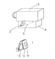
図1は、本発明の傾斜検知ユニットと、そのユニットの設置状態を示した図である。1は、傾斜検知ユニットであり、2は調整ピン、3は監視カメラ本体、4は監視カメラ固定部材である。監視カメラ固定部材4は、壁面や天井面に設置されるアーム(図示省略)等により支持され、軸5を中心に上下方向に回転し、所定の方向で固定されるような構造となっている。
傾斜検知ユニット1はプリント基板12に取り付けられた傾斜センサー11を2組備え、それらを固定具13に取り付けた構造となっている。
【0006】
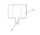
図2は、傾斜センサー11とプリント基板12の拡大図であり、図中の検出軸Yが、鉛直方向を基準として90°以上傾いたときに、検知信号を出力するものである。図4は、固定具13を作るための部材6を示した図である。図に示すように丸穴7をあけたアルミニウム等の板材6を図中の破線部にて折り曲げ加工をして、固定具13が完成される。
【0007】
図3は、傾斜検知ユニット1の拡大図であり、傾斜センサー11が取り付けられた2枚のプリント基板12を固定する固定具13の取付面のなす角度θが、10゜〜20゜の範囲となるような形をしていることを示している。傾斜検知ユニット1は、監視カメラ固定部材の中に調整ピン2に連結される形で固定され、外部に露出した調整ピンの頭をプラスドライバー等の工具によってまわすことによってのみ、回転するようになっている。
【0008】
以上の構成の傾斜検知ユニットを用い、図1に示すように、設置済の監視カメラの内部の傾斜検知ユニットを、図3に示す状態にリセットする。この状態では2つの傾斜センサーは検知出力を出力しておらず、この状態から右または左にθ/2の角度だけ回転すると、一方の傾斜センサーから検知信号が出力されることになる。傾斜検知ユニットは、調整ピン2によって回転するようになっているので、監視カメラの方向が図1の状態よりも上方向、あるいは下方向に向けて固定された場合でも、2つの傾斜センサーの検知出力が共に出力されない状態にリセットすることができる。この傾斜検知ユニットの出力信号を、監視室まで送れば、監視員によって、どの監視カメラが動かされたのか判別することができる。
【0009】
2つの傾斜センサーが、検知信号を出力している状態のときに点灯する表示部(図示省略)を設ければ、調整ピン2の回転による傾斜検知ユニットのリセット作業が容易となる。つまり、一方の傾斜センサーの表示部が点灯した位置と他方の傾斜センサーの表示部が点灯した位置のほぼ中間点にて調整ピンを止めることにより、リセット作業が完了することになる。この表示部は、設置作業や、点検作業を行う時にだけ作動するようにすれば、侵入者による悪用を阻止することができる。
【0010】
【発明の効果】
本発明によれば、2つの傾斜センサーを固定具に取り付けるという簡単な構成でありながら、上下方向に調整可能な監視カメラに追加するだけで、その設置後の方向変更を精度よく、検出することができるようになり、この種の監視カメラに対する妨害行為の検出機能が格段に向上した。
傾斜センサーを取り付ける面のなす角度が小さい程、わずかな傾斜の変化を検出する傾斜検知ユニットが実現される。本発明では、使用する傾斜センサーの検出精度、取り付け機構の寸法精度を考慮して10゜〜20゜としたが、検出しようとする角度範囲に応じて、この角度は適宜設定可能である。
【図面の簡単な説明】
【図1】本発明の傾斜検知ユニットと、そのユニットの設置状態を示した図である。
【図2】本発明に用いる傾斜センサー11とプリント基板12の拡大図である。
【図3】本発明の傾斜検知ユニット1の拡大図である。
【図4】固定具3を作るための部材6の外形を示した図である。
【符号の説明】
1…傾斜検知ユニット
2…調整ピン
3…監視カメラ本体
4…監視カメラ固定部材
5…監視カメラの回転軸
6…固定具3を作るための部材
7…丸穴
11…傾斜センサー
12…プリント基板
13…固定具[0001]
BACKGROUND OF THE INVENTION
The present invention relates to a detection unit that can automatically detect a change in the orientation of a surveillance camera.
[0002]
[Prior art]
Monitoring cameras are installed in stores that require monitoring, important buildings, etc., and the images sent from these monitoring cameras are displayed on the monitor in a monitoring room, etc., and the surveillance staff can constantly monitor or record these images. Surveillance camera systems such as saving are used. In the surveillance camera used in such a system, an imaging target is determined in advance and fixed in that direction.
[0003]
[Problems to be solved by the invention]
However, in such a surveillance camera system, it is assumed that the direction of the surveillance camera is changed by the hand of a person who tries to intrude into the building where the surveillance camera is installed before the invasion action is reached. The In this way, if the direction of the surveillance camera is changed, the monitoring personnel who monitor the video from many surveillance cameras simultaneously with multiple monitors or switch the video sequentially to monitor the abnormality. There is a possibility that it cannot be discovered.
[0004]
[Means for Solving the Problems]
In order to solve the above-described problems, the present invention provides a tilt detection unit for a monitoring camera so that a detection signal is output when the monitoring direction of the monitoring camera is moved from a predetermined installation state. is there.
[0005]
DETAILED DESCRIPTION OF THE INVENTION
FIG. 1 is a view showing a tilt detection unit of the present invention and an installation state of the unit.
The
[0006]
FIG. 2 is an enlarged view of the
[0007]
FIG. 3 is an enlarged view of the
[0008]
Using the tilt detection unit having the above configuration, as shown in FIG. 1, the tilt detection unit inside the installed surveillance camera is reset to the state shown in FIG. In this state, the two tilt sensors do not output the detection output, and when the rotation is rotated to the right or left by an angle of θ / 2, a detection signal is output from one of the tilt sensors. Since the tilt detection unit is rotated by the
[0009]
Provided with a display unit (not shown) that lights when the two tilt sensors are outputting detection signals, the tilt detection unit can be easily reset by rotating the
[0010]
【The invention's effect】
According to the present invention, although it is a simple configuration in which two inclination sensors are attached to a fixture, it is possible to accurately detect a change in direction after installation by simply adding to a surveillance camera that can be adjusted in the vertical direction. The ability to detect sabotage for this type of surveillance camera has been greatly improved.
As the angle formed by the surface on which the tilt sensor is attached is smaller, a tilt detection unit that detects a slight tilt change is realized. In the present invention, the angle is set to 10 ° to 20 ° in consideration of the detection accuracy of the tilt sensor to be used and the dimensional accuracy of the mounting mechanism, but this angle can be appropriately set according to the angle range to be detected.
[Brief description of the drawings]
FIG. 1 is a view showing a tilt detection unit of the present invention and an installation state of the unit.
FIG. 2 is an enlarged view of a
FIG. 3 is an enlarged view of the
FIG. 4 is a view showing an outer shape of a
[Explanation of symbols]
DESCRIPTION OF
Claims (1)
Priority Applications (1)
| Application Number | Priority Date | Filing Date | Title |
|---|---|---|---|
| JP2000045758A JP4336843B2 (en) | 2000-02-23 | 2000-02-23 | Tilt detection unit for surveillance cameras |
Applications Claiming Priority (1)
| Application Number | Priority Date | Filing Date | Title |
|---|---|---|---|
| JP2000045758A JP4336843B2 (en) | 2000-02-23 | 2000-02-23 | Tilt detection unit for surveillance cameras |
Publications (3)
| Publication Number | Publication Date |
|---|---|
| JP2001238102A JP2001238102A (en) | 2001-08-31 |
| JP2001238102A5 JP2001238102A5 (en) | 2007-04-05 |
| JP4336843B2 true JP4336843B2 (en) | 2009-09-30 |
Family
ID=18568294
Family Applications (1)
| Application Number | Title | Priority Date | Filing Date |
|---|---|---|---|
| JP2000045758A Expired - Fee Related JP4336843B2 (en) | 2000-02-23 | 2000-02-23 | Tilt detection unit for surveillance cameras |
Country Status (1)
| Country | Link |
|---|---|
| JP (1) | JP4336843B2 (en) |
Families Citing this family (1)
| Publication number | Priority date | Publication date | Assignee | Title |
|---|---|---|---|---|
| JP4578743B2 (en) * | 2001-09-28 | 2010-11-10 | セコム株式会社 | Surveillance camera device |
-
2000
- 2000-02-23 JP JP2000045758A patent/JP4336843B2/en not_active Expired - Fee Related
Also Published As
| Publication number | Publication date |
|---|---|
| JP2001238102A (en) | 2001-08-31 |
Similar Documents
| Publication | Publication Date | Title |
|---|---|---|
| WO2006091422A2 (en) | Glassbreak noise detector and video positioning locator | |
| KR20120029321A (en) | Apparatus for preventing scattered reflection of lighting in monitoring camera | |
| ES2397766T3 (en) | Security system against displacement for surveillance cameras | |
| CN107466413B (en) | System and method for field alignment | |
| JP4336843B2 (en) | Tilt detection unit for surveillance cameras | |
| CN205453969U (en) | Real -time monitoring device | |
| US10969093B1 (en) | Rotatable lamp and two cameras for detecting movement | |
| JP3286444B2 (en) | Fire detector | |
| JP2015041913A (en) | Monitor system | |
| KR100869048B1 (en) | Multi function sensor | |
| JP2005077279A (en) | Smoke sensing system | |
| JP2001086375A (en) | Camera with rotary base | |
| JP2001145004A (en) | Supervisory camera | |
| KR101804309B1 (en) | Tracking cctv | |
| JP2001024916A (en) | Monitor camera device and method for setting its monitor area | |
| JP5332767B2 (en) | Origin detection method, origin detection apparatus, and surveillance camera apparatus | |
| JPH04108274A (en) | Monitor camera | |
| JPH0844962A (en) | Monitor camera device | |
| JP2004312098A (en) | Monitoring camera apparatus | |
| JPH06111149A (en) | Monitoring sensor | |
| JP2605026Y2 (en) | Ceiling / wall mounting fixture | |
| JP4151337B2 (en) | Pyroelectric sensor and illumination device with pyroelectric sensor | |
| JPH07226869A (en) | Case containing-type video camera monitoring device | |
| CN217640357U (en) | Building monitoring camera shooting intelligent safety alarm device | |
| CN220273773U (en) | Image pickup apparatus |
Legal Events
| Date | Code | Title | Description |
|---|---|---|---|
| A521 | Request for written amendment filed |
Free format text: JAPANESE INTERMEDIATE CODE: A523 Effective date: 20070216 |
|
| A621 | Written request for application examination |
Free format text: JAPANESE INTERMEDIATE CODE: A621 Effective date: 20070216 |
|
| A131 | Notification of reasons for refusal |
Free format text: JAPANESE INTERMEDIATE CODE: A131 Effective date: 20090210 |
|
| A521 | Request for written amendment filed |
Free format text: JAPANESE INTERMEDIATE CODE: A523 Effective date: 20090413 |
|
| TRDD | Decision of grant or rejection written | ||
| A01 | Written decision to grant a patent or to grant a registration (utility model) |
Free format text: JAPANESE INTERMEDIATE CODE: A01 Effective date: 20090512 |
|
| A01 | Written decision to grant a patent or to grant a registration (utility model) |
Free format text: JAPANESE INTERMEDIATE CODE: A01 |
|
| A61 | First payment of annual fees (during grant procedure) |
Free format text: JAPANESE INTERMEDIATE CODE: A61 Effective date: 20090611 |
|
| R150 | Certificate of patent or registration of utility model |
Free format text: JAPANESE INTERMEDIATE CODE: R150 |
|
| FPAY | Renewal fee payment (event date is renewal date of database) |
Free format text: PAYMENT UNTIL: 20120710 Year of fee payment: 3 |
|
| LAPS | Cancellation because of no payment of annual fees |


