JP4336662B2 - Control device for cable drawing car - Google Patents
Control device for cable drawing car Download PDFInfo
- Publication number
- JP4336662B2 JP4336662B2 JP2005076658A JP2005076658A JP4336662B2 JP 4336662 B2 JP4336662 B2 JP 4336662B2 JP 2005076658 A JP2005076658 A JP 2005076658A JP 2005076658 A JP2005076658 A JP 2005076658A JP 4336662 B2 JP4336662 B2 JP 4336662B2
- Authority
- JP
- Japan
- Prior art keywords
- drum
- detector
- cable
- stop
- deceleration
- Prior art date
- Legal status (The legal status is an assumption and is not a legal conclusion. Google has not performed a legal analysis and makes no representation as to the accuracy of the status listed.)
- Expired - Fee Related
Links
Images


Landscapes
- Electric Cable Installation (AREA)
Description
本願発明は、例えば電柱間に架設されている送電経路の補修・改修等の配電線工事に使用されるケーブル延線車に関し、特に車輌上に複数個のケーブルドラムを同期して周回させるようにしたケーブル延線車の制御装置に関するものである。 The present invention relates to a cable extension car used for distribution line work such as repair and repair of a power transmission path installed between utility poles, for example, in particular, so that a plurality of cable drums circulate synchronously on a vehicle. The present invention relates to a control device for a cable drawing car.
既設の送電経路を補修又は改修する際には、一般に、その送電経路のうちの補修・改修範囲をバイパスする仮設送電路を設け、無停電で工事を行っている。このような無停電工法を行うには、仮設送電線としてのケーブルを延出及び回収するためのケーブル延線車が使用される。 When repairing or refurbishing an existing power transmission path, a temporary power transmission path that bypasses the repair / repair range of the power transmission path is generally provided, and construction is performed without any power outage. In order to perform such an uninterruptible construction method, a cable extension vehicle for extending and collecting a cable as a temporary power transmission line is used.
この種のケーブル延線車として、従来から、例えば実開平3−55339号公報(特許文献1)に示されるものがある。この公知例のケーブル延線車は、車輌上において複数個(6個)のケーブルドラムをドラム周回装置により同期して周回させ得るようになっている。尚、各ケーブルドラムには、種類の異なるケーブルが巻回される。 Conventionally, as this type of cable-drawing wheel, there is one disclosed in, for example, Japanese Utility Model Publication No. 3-55339 (Patent Document 1). This known example of a cable-drawn vehicle is configured such that a plurality (six) of cable drums can be rotated in synchronism with a drum rotating device on the vehicle. Note that different types of cables are wound around each cable drum.
そして、この公知のケーブル延線車では、操作部において所望のケーブルドラムを指定すると、その指定した1つのケーブルドラムがケーブル繰出し巻取り位置となるドラム使用位置まで移動してそこで停止し、そのドラム使用位置にあるケーブルドラムからケーブルを繰出して使用し得るようになっている。 In this known cable extension wheel, when a desired cable drum is designated in the operation section, the designated one cable drum moves to a drum use position which becomes a cable feed winding position, and stops there. The cable can be fed out from the cable drum at the use position.
又、この公知例(実開平3−55339号公報)のケーブル延線車では、ケーブルドラムをドラム脱着位置において脱着させ得るようになっている。 Further, in this known example (Japanese Utility Model Publication No. 3-55339), the cable drum can be attached / detached at the drum attaching / detaching position.
上記した実開平3−55339号公報のケーブル延線車には、指定した1つのケーブルドラムを呼出したときに、その指定ケーブルドラムが目的位置(ドラム使用位置又はドラム脱着位置)に達する直前で、減速用検出器(リミットスイッチ)からの信号でドラム周回装置の駆動スピードを減速させた後、停止用検出器(リミットスイッチ)からの信号でドラム周回装置を停止させるようになっている。尚、このように、ドラム周回装置及び各ケーブルドラムを、所定の低速まで減速させた後、停止させるようにすると、指定ケーブルドラムを正確に目的位置に停止させ得るとともに、停止時のショックを小さくできる。 In the cable extension wheel of the above-mentioned Japanese Utility Model Laid-Open No. 3-55339, immediately before a designated cable drum is called, the designated cable drum reaches a target position (drum use position or drum detachment position). After the driving speed of the drum circulating device is decelerated by a signal from a deceleration detector (limit switch), the drum circulating device is stopped by a signal from a stop detector (limit switch). In this way, if the drum circulating device and each cable drum are decelerated to a predetermined low speed and then stopped, the designated cable drum can be accurately stopped at the target position and the shock at the time of stopping can be reduced. it can.
又、上記した実開平3−55339号公報のケーブル延線車では、各ケーブルドラムを正逆両方向に周回させ得るようになっており、且つドラム使用位置(ケーブル繰出し巻取り位置)とドラム脱着位置の両位置でそれぞれ停止させるようになっているので、減速用検出器と停止用検出器が4セット(合計8個)ある。 Moreover, in the cable extension wheel of the above-mentioned Japanese Utility Model Publication No. 3-55339, each cable drum can be rotated in both forward and reverse directions, and the drum use position (cable unwinding / winding position) and drum removal / attachment position. Therefore, there are 4 sets (8 in total) of deceleration detectors and stop detectors.
尚、上記した実開平3−55339号公報のケーブル延線車では、ドラム周回装置として、回転中心を持つ回転体を回転させることによって回転体外周部に装着した各ケーブルドラムを周回させるようにしたものが採用されているが、この種のケーブル延線車におけるドラム周回装置として、例えば実公平3−4095号公報(特許文献2)に示されるようなチエーン駆動式のものもある。 Incidentally, in the cable extension wheel disclosed in Japanese Utility Model Laid-Open No. 3-55339, the cable drum mounted on the outer periphery of the rotating body is rotated by rotating a rotating body having a rotation center as a drum rotating device. However, there is a chain drive type as shown in, for example, Japanese Utility Model Publication No. 3-4095 (Patent Document 2) as a drum rotating device in this type of cable extension wheel.
ところが、上記特許文献1(実開平3−55339号公報)のケーブル延線車では、次のような問題があった。 However, the cable-drawn vehicle disclosed in Patent Document 1 (Japanese Utility Model Publication No. 3-55339) has the following problems.
まず、指定したケーブルドラムを目的位置で正確に停止させるために、減速用検出器と停止用検出器を使用しているが、もし停止用検出器が異常なとき(例えば、断線や検出器自体の故障時)には、指定したケーブルドラムが目的位置(ドラム使用位置又はドラム脱着位置)を過ぎてもドラム周回装置(モータ)に対して停止信号が発せられないので、各ケーブルドラムが周回し続けるという問題が発生する。 First, in order to stop the specified cable drum accurately at the target position, a deceleration detector and a stop detector are used. If the stop detector is abnormal (for example, disconnection or detector itself) When the specified cable drum passes the target position (drum use position or drum attachment / detachment position), a stop signal is not sent to the drum circulator (motor). The problem of continuing.
又、停止用検出器が正常で減速用検出器が異常なときでも、減速用検出器が作動しないと停止用検出器が作動しない設定のものでは、各ケーブルドラムが周回し続けると考えられる。尚、ケーブルドラムが周回し続ける場合には、緊急停止スイッチを操作してドラム周回装置を強制停止させる必要がある。 Further, even when the stop detector is normal and the deceleration detector is abnormal, it is considered that each cable drum continues to circulate in a setting in which the stop detector does not operate unless the deceleration detector operates. When the cable drum continues to circulate, it is necessary to forcibly stop the drum circulator by operating the emergency stop switch.
又、上記公知(実開平3−55339号公報)のケーブル延線車では、各ケーブルドラムを正逆両方向に周回させ得るとともに、ドラム使用位置(ケーブル繰出し巻取り位置)とドラム脱着位置の両位置でそれぞれ停止させるようになっているので、減速用検出器と停止用検出器が4セット(合計8個)あるが、各ケーブルドラムの周回又は停止に異常があったときに、どの検出器に欠陥があるのか判別するのが難しく、修理・部品交換等の保守作業を行うまでの時間が長くかかるという問題もあった。 Moreover, in the above-mentioned known (Japanese Utility Model Publication No. 3-55339) cable extension wheel, each cable drum can be rotated in both forward and reverse directions, and both the drum use position (cable unwinding position) and the drum removal position Since there are 4 sets of deceleration detectors and stop detectors (8 in total), when any abnormality occurs in the circulation or stop of each cable drum, There is also a problem that it is difficult to determine whether there is a defect, and it takes a long time to perform maintenance work such as repair and replacement of parts.
本願発明は、上記した事情に鑑み、ケーブル延線車において、減速用検出器や停止用検出器が異常になったときに、ケーブルドラムが周回し続ける(暴走する)というトラブルを解消し得るようにするとともに、減速用検出器や停止用検出器に異常が発生したときに、その異常検出器を速やかに判別し得るようにすることを目的としている。 In view of the above circumstances, the present invention can solve the problem that the cable drum continues to run (runaway) when the deceleration detector or the stop detector becomes abnormal in the cable-drawn vehicle. In addition, when an abnormality occurs in the deceleration detector or the stop detector, the object is to be able to quickly determine the abnormality detector.
本願発明は、上記課題を解決するための手段として次の構成を有している。尚、本願発明は、ケーブル延線車を対象にしている。 The present invention has the following configuration as means for solving the above problems. The present invention is directed to a cable-drawn vehicle.
本願請求項1の発明
本願請求項1で使用されるケーブル延線車は、車輌上において複数個のケーブルドラムをドラム周回装置により同期して周回させるとともに、ドラム使用位置においてケーブルドラムのケーブルを繰出したり巻取ったりし得るようにしたものである。尚、この請求項1で使用されるケーブル延線車のドラム周回装置は、各ケーブルドラムを一方向にのみ周回させるようにしたものも採用できる。
Invention of Claim 1 The cable extension wheel used in claim 1 of the present invention rotates a plurality of cable drums synchronously by a drum rotating device on the vehicle and feeds the cable of the cable drum at the drum use position. It can be rolled up and wound up. In addition, as the drum rotating device for the cable-drawing wheel used in the first aspect, one in which each cable drum is rotated only in one direction can be adopted.
このケーブル延線車のドラム周回装置としては、例えば上記特許文献1(実開平3−55339号公報)のように、回転中心をもつ回転体の外周部分に複数個のケーブルドラムを取付けて、そのケーブルドラム付き回転体を回転体駆動装置で回転させるようにしたものや、上記特許文献2(実公平3−4095号公報)のように、チエーンに所定間隔をもって複数個のケーブルドラムを取付けて、そのケーブルドラム付きのチエーンをチエーン駆動装置で循環させるようにしたもの、等が採用できる。 As a drum circulator for this cable extension wheel, a plurality of cable drums are attached to the outer peripheral portion of a rotating body having a center of rotation, for example, as in Patent Document 1 (Japanese Utility Model Publication No. 3-55339). A rotating body with a cable drum is rotated by a rotating body drive device, or a plurality of cable drums are attached to a chain at a predetermined interval, as in Patent Document 2 (Japanese Utility Model Publication No. 3-4095), A chain with a cable drum that is circulated by a chain drive device can be used.
そして、このケーブル延線車における請求項1の発明の制御装置は、各ケーブルドラムが通過する度にその各ケーブルドラムの通過をそれぞれ検出する減速用検出器と停止用検出器とを1組とする検出器セットと、減速用検出器のカウント数を計数する減速用検出器カウンターと、停止用検出器のカウント数を計数する停止用検出器カウンターとを有し、指定した1つのケーブルドラムがドラム使用位置まで移動する間に減速用検出器カウンターと停止用検出器カウンターがそれぞれカウントする回数に基いてドラム周回装置を減速させた後に停止させるようにしたドラム周回制御手段を備えているとともに、減速用検出器カウンターの累積カウント数と停止用検出器カウンターの累積カウント数との差が2以上になったときに判別信号を出力する判別手段を用いて、判別手段が判別信号を出力したときにドラム周回装置を停止させるようにしたものである。 The control device according to the first aspect of the present invention is a set of a deceleration detector and a stop detector for detecting the passage of each cable drum each time each cable drum passes. A detector set for decelerating, a decelerating detector counter for counting the count number of the decelerating detector, and a stop detector counter for counting the count number of the decelerating detector. Drum rotation control means for stopping the drum rotation device after decelerating the drum rotation device based on the number of times counted by the deceleration detector counter and the stop detector counter while moving to the drum use position, When the difference between the cumulative count of the deceleration detector counter and the cumulative count of the stop detector counter is 2 or more, a discrimination signal is output. Using a discriminating means for, in which discriminating means has a drum circulator When outputting discrimination signal so as to stop.
この請求項1のケーブル延線車の制御装置は、次のように機能する。尚、以下の説明でいう検出器の異常とは、該検出器部分をケーブルドラムが通過しても、検出信号を発しない状態やONのままで戻らない(OFFにならない)状態のことを意味する。 The control device for the cable-drawing vehicle according to claim 1 functions as follows. In the following description, the abnormality of the detector means a state in which a detection signal is not generated even if the cable drum passes through the detector portion, or a state in which the detection signal is not turned on or returned (not turned off). To do.
まず、所望のケーブルドラムの選択スイッチを押すと、減速用検出器及び停止用検出器が共に正常であれば、減速用検出器部分及び停止用検出器部分を各ケーブルドラムが順次通過する度に両検出器からそれぞれ検出信号が出力されて、減速用検出器カウンター及び停止用検出器カウンターがそれぞれカウント数を加算していくが、その両検出器がいずれも正常であれば各カウンターの累積カウント数の差が「2」に達することはない。従って、指定したケーブルドラムがドラム使用位置まで達するのに、各検出器部分をケーブルドラムが2回以上通過する必要がある場合でも、判別手段からは判別信号が発せられず、各カウンターのカウントアップ信号に基いてドラム周回装置が通常の減速→停止動作を行い、指定したケーブルドラムを所定のドラム使用位置で自動停止させる。尚、指定したケーブルドラムがドラム使用位置の周回方向上手側の隣りに位置するものでは、各カウンターはそれぞれカウント数「1」のみでカウントアップ信号を発して、減速→停止動作を行わせるので、当然に各カウンターの累積カウント数の差が「2」になることはない。 First, when the selection switch for the desired cable drum is pressed, if both the deceleration detector and the stop detector are normal, each cable drum passes through the deceleration detector portion and the stop detector portion sequentially. Detection signals are output from both detectors, and the decelerating detector counter and stop detector counter add the counts. If both detectors are normal, the cumulative count of each counter The number difference never reaches “2”. Therefore, even if the cable drum needs to pass through each detector part more than once for the designated cable drum to reach the drum use position, the discrimination means does not issue a discrimination signal, and each counter counts up. Based on the signal, the drum circulator performs normal deceleration → stop operation, and the designated cable drum is automatically stopped at a predetermined drum use position. In addition, when the designated cable drum is located adjacent to the upper side of the circumferential direction of the drum use position, each counter emits a count-up signal with only the count number “1”, and performs a deceleration → stop operation. Naturally, the difference between the cumulative counts of the counters does not become “2”.
他方、停止用検出器に異常があると、該停止用検出器部分をケーブルドラムが通過しても停止用検出器から検出信号が出力されないので、停止用検出器カウンターにはカウント数が加算されない(「0」カウントのままである)。従って、通常では、停止用検出器に基く自動停止制御は実行されない。尚、このとき減速用検出器が正常であれば、減速用検出器カウンターが減速信号発信回数だけカウントした時点で、ドラム周回装置に対して減速信号が発せられる。 On the other hand, if there is an abnormality in the stop detector, no detection signal is output from the stop detector even if the cable drum passes through the stop detector portion, so the count number is not added to the stop detector counter. (It remains “0” count). Therefore, normally, the automatic stop control based on the stop detector is not executed. If the deceleration detector is normal at this time, a deceleration signal is issued to the drum rotating device when the deceleration detector counter counts the number of times of deceleration signal transmission.
ところで、停止用検出器が異常で減速用検出器が正常であると、停止用検出器カウンターにはカウント数が加算されない(「0」カウントのままである)が、減速用検出器部分を各ケーブルドラムが通過する度に減速用検出器カウンターはカウント数を加算していき、該減速用検出器カウンターの累積カウント数が「2」になったときに、判別手段が各累積カウント数の差「2」を読み取って該判別手段から判別信号が出力され、その判別信号に基いてドラム周回装置を自動停止させるようになる。 By the way, if the stop detector is abnormal and the deceleration detector is normal, the count number is not added to the stop detector counter (it remains “0” count), Each time the cable drum passes, the deceleration detector counter increments the count. When the cumulative count of the deceleration detector counter reaches “2”, the discriminating means determines the difference between the cumulative counts. When “2” is read, a discrimination signal is output from the discrimination means, and the drum circulating device is automatically stopped based on the discrimination signal.
逆に、停止用検出器が正常で減速用検出器が異常であると、ケーブルドラムが移動しても減速用検出器カウンターは「0」カウントのままであるが、停止用検出器カウンターの累積カウント数が「2」になったときに、判別手段が各カウンターの累積カウント数の差「2」を読み取って、上記と同様にドラム周回装置を強制的に停止させるようになる。 Conversely, if the stop detector is normal and the deceleration detector is abnormal, the deceleration detector counter remains “0” even if the cable drum moves, but the stop detector counter is cumulative. When the count number becomes “2”, the discriminating means reads the difference “2” in the accumulated count number of each counter, and forcibly stops the drum circulating device as described above.
この請求項1の制御装置では、減速用検出器が異常であっても停止用検出器が単独で機能するようにできるが、その場合、指定したケーブルドラムがドラム使用位置の周回方向上手側の隣りに位置するものでは、判別手段が各カウンターの累積カウント数の差「2」を読み取る前に、停止用検出器カウンターがカウント数「1」でカウントアップ信号を発してドラム周回装置を直ちに停止させるようになる。 In the control device according to the first aspect, even if the deceleration detector is abnormal, the stop detector can function independently. In this case, the designated cable drum is located on the upper side in the circumferential direction of the drum use position. In the adjacent position, before the discriminating means reads the difference “2” in the accumulated count number of each counter, the stop detector counter issues a count-up signal with the count number “1” and immediately stops the drum circulating device. Will come to let you.
尚、ケーブルドラムを呼出したときに、減速用検出器と停止用検出器の両方が異常であると、ドラム周回装置は作動をし続けるが、そのときには緊急停止スイッチを押して強制停止させることができる。 If both the deceleration detector and the stop detector are abnormal when the cable drum is called, the drum circulator continues to operate, but at that time, the emergency stop switch can be pressed to forcibly stop. .
又、上記判別手段によるドラム周回装置の停止時、及び上記緊急停止スイッチによるドラム周回装置の停止時には、それぞれケーブルドラムの周回スピートをスローダウンさせながら停止させるようにしてもよい。 Further, when the drum circulator is stopped by the determining means and when the drum circulator is stopped by the emergency stop switch, the rotation speed of the cable drum may be slowed down and stopped.
本願請求項2の発明
本願請求項2で使用されるケーブル延線車は、車輌上において複数個のケーブルドラムをドラム周回装置により同期して周回させるとともに、ドラム脱着位置においてケーブルドラムをドラム周回装置に対して装着したり離脱させたりし得るようにしたものを採用している。ドラム脱着位置は、通常はケーブルドラム(ドラム軸)の周回軌道上におけるドラム使用位置(ケーブル繰出し巻取り位置)とは別の位置に設定される。尚、この請求項2で使用されるケーブル延線車は、上記請求項1の説明で使用したケーブル延線車をそのまま援用できる。
The invention of
この請求項2のケーブル延線車の制御装置は、指定した1つのケーブルドラムをドラム脱着位置まで移動させる際に機能するものである。
The control device for the cable-drawing wheel according to
そして、この請求項2の制御装置は、各ケーブルドラムが通過する度にそのケーブルドラムの通過を検出する減速用検出器と停止用検出器とを1組とする検出器セットと、減速用検出器のカウント数を計数する減速用検出器カウンターと、停止用検出器のカウント数を計数する停止用検出器カウンターとを有し、指定した1つのケーブルドラムがドラム脱着位置まで移動する間に減速用検出器カウンターと停止用検出器カウンターがそれぞれカウントする回数に基いてドラム周回装置を減速させた後に停止させるようにしたドラム周回制御手段を備えるとともに、減速用検出器カウンターの累積カウント数と停止用検出器カウンターの累積カウント数との差が2以上になったときに判別信号を出力する判別手段を用いて、判別手段が判別信号を出力したときにドラム周回装置を停止させるようにしたものである。
The control device according to
この請求項2の制御装置は、上記した請求項1の制御装置と同様に機能するものであり、ケーブルドラムが移動中に、各カウンター(減速用検出器カウンターと停止用検出器カウンター)の累積カウント数の差が「2」に達すると、それを判別手段が判別して、該判別手段からの判別信号によりドラム周回装置を強制停止させるようになっている。
The control device according to
本願請求項3の発明
本願請求項3の発明は、上記請求項1又は2の制御装置において、ドラム周回装置として、各ケーブルドラムを正逆両方向に周回させ得るようにしたものを採用して、指定したケーブルドラムを短い順路で目的位置まで移動させるようにしている。
Invention of claim 3 of the present application The invention of claim 3 of the present application employs a control device according to
又、減速用検出器と停止用検出器とを1組とする検出器セットは、ケーブルドラム正方向周回時に機能するものとケーブルドラム逆方向周回時に機能するものとの2セット使用している。尚、該2セットの検出器セットは、それぞれ減速用検出器が先で停止用検出器が後に操作されるように設置している。 In addition, two detector sets, one that functions as a decelerating detector and one as a stop detector, function when the cable drum rotates in the forward direction and the function that functions when the cable drum rotates in the reverse direction. The two sets of detectors are installed such that the deceleration detector is operated first and the stop detector is operated later.
この請求項3の制御装置では、1つのケーブルドラムを指定すると、その指定ケーブルドラムが目的位置(ドラム使用位置又はドラム脱着位置)に近い方向に周回するが、そのとき2セットの検出器セットのうち、減速用検出器が先に操作される側の検出器セットのみが機能するようになっている。 In the control device according to the third aspect, when one cable drum is designated, the designated cable drum circulates in a direction close to the target position (drum use position or drum attachment / detachment position). Of these, only the detector set on the side on which the deceleration detector is operated first functions.
尚、2セットの検出器セットの各検出器(合計4個)には、それぞれ減速用検出器カウンター又は停止用検出器カウンターが接続されていて、上記請求項1又は請求項2の制御と同様に、機能している検出器セットのうちのいずれかの検出器が異常になっているときには、各カウンターの累積カウント数の差が「2」になった時点でドラム周回装置を停止させるようになっている。
Incidentally, a deceleration detector counter or a stop detector counter is connected to each detector (two in total) of the two sets of detectors, and is the same as the control of claim 1 or
尚、この請求項3のように、2セットの検出器セットを使用したものでは、合計4つの検出器の各カウンターをそれぞれ機能する状態にしておき、指定した1セットの検出器セットの両方の検出器が共に異常なときに、各異常検出器のカウンターのカウント数(両方とも「0」カウント)と、別の正常な検出器セットのカウンターのカウント数とを比較して、いずれか1つの正常検出器のカウンターのカウント数が「2」になった時点で(異常検出器のカウンターと正常検出器のカウンターの累積カウント数の差が「2」になる)、上記と同様にドラム周回装置を停止させるようにしてもよい。 As in claim 3, when two detector sets are used, each counter of a total of four detectors is set to a functioning state, and both of the designated one detector set are set. When both detectors are abnormal, the counter count of each abnormal detector (both “0” count) is compared with the counter count of another normal detector set, When the count number of the counter of the normal detector becomes “2” (the difference between the cumulative count number of the counter of the abnormal detector and the counter of the normal detector becomes “2”), the drum circulating device as described above May be stopped.
本願請求項4の発明
本願請求項4の発明は、上記請求項1から3のいずれか1項の制御装置において、作動すべき減速用検出器及び停止用検出器のうち、ケーブルドラムが通過したにもかかわらずカウンターがカウントしない異常検出器がある場合に、その異常検出器を報知するエラー報知手段を設けている。
Invention of
異常な検出器の認定は、減速用検出器カウンターと停止用検出器カウンターの各累積カウント数の差が「2」になったときに、その2つのカウンターのうちカウント数が「0」のままのカウンターが対応する検出器が異常検出器として認定される。 An abnormal detector is certified when the difference between the accumulated counter numbers of the deceleration detector counter and the stop detector counter is “2”, and the count number of the two counters remains “0”. The detector corresponding to the counter is certified as an abnormal detector.
エラー報知手段としては、例えば液晶表示部にどの検出器かを示すコード番号で表示させるようにしたもの、又は複数個(各検出器の数と同数)の表示灯を使用して異常検出器を点灯表示させるもの、あるいは音声で異常検出器を報知させるもの、等を採用できる。 As the error notification means, for example, an abnormality detector can be displayed by using a display light having a code number indicating which detector is displayed on the liquid crystal display unit, or a plurality of (the same number as each detector) indicator lights. A light-up display or a sound-informing abnormality detector can be employed.
本願請求項5の発明
本願請求項5の発明は、上記請求項4の制御装置において、1セットとなる減速用検出器と停止用検出器において、減速用検出器が正常に作動しないときは、停止用検出器カウンターが停止に必要なカウント数を計数しても停止用検出器によるドラム周回装置への停止信号が出力されないようにしている。
Invention of
ところで、上記請求項4では、異常検出器を報知させるのに両カウンターの累積カウント数の差が「2」で機能するようにしているが、指定したケーブルドラムが目的位置まで移動する距離が短い場合(カウンターのカウント数が「1」のみである場合)で、上記判別手段が作動することなくドラム周回装置が停止されてしまう場合には、請求項4のエラー報知手段にエラー報知されなくなる。
By the way, in
そこで、この請求項5の制御装置では、減速用検出器が異常であるときには、指定したケーブルドラムが目的位置に近い場合(移動距離が1カウント分)であっても、ケーブルドラムが2カウント分だけ継続して移動するようにしている。尚、減速用検出器が異常時には、ケーブルドラムが2カウント分移動すると各カウンターの累積カウント数の差が「2」になり、上記のように判別手段によるドラム周回装置への停止機能とエラー報知手段への異常検出器の報知機能が生じる。
Therefore, in the control device according to
本願発明のケーブル延線車の制御装置には、次のような効果がある。 The control device for the cable-drawing wheel of the present invention has the following effects.
本願請求項1の発明の効果
本願請求項1の制御装置では、指定したケーブルドラムをドラム使用位置で停止させる際に、1セットの検出器(減速用検出器と停止用検出器)のうち、いずれか一方の検出器に異常があるときには、各検出器のカウンターの累積カウント数の差が「2」以上になった時点で、ドラム周回装置を強制停止させることができるので、ケーブルドラムが周回し続ける(暴走する)というトラブルを未然に防止できるという効果がある。
Effect of the Invention of Claim 1 In the control device of claim 1 of the present application, when stopping the designated cable drum at the drum use position, among one set of detectors (deceleration detector and stop detector), If any one of the detectors is abnormal, the drum circulator can be forcibly stopped when the difference between the cumulative counts of the counters of the detectors becomes "2" or more. There is an effect that the trouble of continuing to run (runaway) can be prevented in advance.
本願請求項2の発明の効果
本願請求項2の制御装置では、指定したケーブルドラムをドラム脱着位置で停止させる際に、上記請求項1の場合と同様に1セットの検出器(減速用検出器と停止用検出器)のうち、いずれか一方の検出器に異常があるときには、各検出器のカウンターの累積カウント数の差が「2」以上になった時点で、ドラム周回装置を強制停止させることができるので、ケーブルドラムが周回し続ける(暴走する)というトラブルを未然に防止できるという効果がある。
Effect of the Invention of
本願請求項3の発明の効果
本願請求項3の発明の制御装置では、ドラム周回装置として、各ケーブルドラムを正逆両方向に周回させ得るようにしたものを採用して、指定したケーブルドラムを短い順路で目的位置まで移動させるようにしているので、上記請求項1又は2の効果に加えて、指定したケーブルドラムを短時間で目的位置まで移動させることができるという効果がある。
Effect of the Invention of Claim 3 In the control device of the invention of claim 3 of the present application, a drum circulator that can circulate each cable drum in both forward and reverse directions is adopted, and the designated cable drum is short. In addition to the effect of the first or second aspect, there is an effect that the designated cable drum can be moved to the target position in a short time.
本願請求項4の発明の効果
本願請求項4の発明では、異常な検出器がある場合に、その異常検出器をエラー報知手段に報知させるようになっているので、上記請求項1から3の効果に加えて、異常検出器がどれであるかを容易に識別でき、修理や部品交換等の保守作業時に異常検出器を特定する作業が不要となって保守作業時間を短縮できるという効果がある。
Effect of the Invention of
本願請求項5の発明の効果
本願請求項5の発明の制御装置では、1セットとなる減速用検出器と停止用検出器において、減速用検出器が正常に作動しないときは、停止用検出器カウンターが停止に必要なカウント数を計数しても停止用検出器によるドラム周回装置への停止信号が出力されないようにしている。そして、減速用検出器が異常である場合には、ケーブルドラムが2カウント分移動した時点で判別手段が作動するようになる。従って、この請求項5の制御装置では、上記請求項4の効果に加えて、指定したケーブルドラムが1カウント分の移動量しか指示されない場合でも、確実に異常検出器をエラー報知手段に報知させることができるという効果がある。
Effect of the Invention of
以下、図1〜図6を参照して本願実施例のケーブル延線車の制御装置を説明する。 Hereinafter, a control device for a cable-drawn vehicle according to an embodiment of the present invention will be described with reference to FIGS.
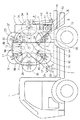
この実施例で使用されるケーブル延線車は、図1に示すように、車輌1の荷台11上において複数個(図示例では6個)のケーブルドラム3A〜3Fをドラム周回装置2で周回させ得るようにしている。尚、図1のケーブル延線車は、特許文献1に示す実開平3−55339号公報に示されるものとほぼ同じものである。
As shown in FIG. 1, in the cable extension vehicle used in this embodiment, a plurality of (six in the illustrated example) cable drums 3 </ b> A to 3 </ b> F are circulated by the
ドラム周回装置2は、この実施例では回転体21を回転体駆動装置25で回転させるようにしたものを採用している。
In this embodiment, the
回転体21は、回転中心(回転軸22部分)から等角度間隔をもって6本のアーム23,23・・を延出させた側板を、車幅方向に所定間隔をもって一対有したものである。そして、この回転体21は、車輌荷台11上に設けた左右一対の支柱12間に回転軸22で回転自在に支持している。
The rotating
回転体21の各アーム23,23・・(それぞれ左右一対ある)の先端部付近には、それぞれケーブルドラム3A〜3Fが1つずつ装着されている。この実施例では、各アーム23の先端部にそれぞれ長溝があって、該長溝内でケーブルドラム(3A〜3F)のドラム軸がスライドし得るようになっているが、各ドラム軸は周回軌条(非円形で左右一対ある)28でガイドされていて、各ケーブルドラム3A〜3Fが周回軌条28に沿って周回するようになっている。又、各アーム23,23・・には、後述する各検出器(8A〜8D、9A〜9D)を操作するカム24が設けられている。
One
このケーブルドラム付き回転体21は、モータ(油圧駆動式)26及び動力伝達部材27からなる回転体駆動装置25で回転せしめられる。回転体駆動装置25のモータ26は、正逆両方向に作動可能なものが採用されていて、後述するコントローラ61からの指令で回転体21を正逆各方向に回転させ得るようになっている。
The rotating
この実施例のケーブル延線車では、周回軌条28における車輌荷台11の最後端寄り位置(回転軸22と同高さ)がケーブルの繰出し・巻取りを行うドラム使用位置Pとなり、該ドラム使用位置Pより所定角度(例えば約50°)だけ下方に偏位する位置がドラム脱着位置Qとなっている。
In the cable extension vehicle of this embodiment, the position closer to the rearmost end of the vehicle loading platform 11 (the same height as the rotary shaft 22) in the orbiting
ドラム使用位置Pにあるケーブルドラム(図1では符号3A)は、ドラム駆動装置4でケーブル繰出し方向及びケーブル巻取り方向に回転せしめられる。このドラム駆動装置4は、正逆回転可能なモータ(油圧駆動式)41と動力伝達部材42とを有している。尚、動力伝達部材42の上部側部材(スプロケット)は、側板13で支持されている。そして、ケーブルドラムがドラム使用位置Pにあるとき(例えば図1の3A)には、ケーブルドラム3A側のギヤ34とドラム駆動装置4側のギヤ44が噛み合っており、その状態でモータ41を正逆いずれかの方向に回転させることにより、当該ケーブルドラム3Aをケーブル繰出し方向又はケーブル巻取り方向に回転させ得るようになっている。
The cable drum (
ドラム脱着位置Qには、ケーブルドラム(3A〜3F)の軸をアーム23の先端部及び周回軌条28内に装着したり離脱させたりするためのドラム脱着装置5が設けられている。このドラム脱着装置5は、図4に示すようにシリンダ(左右一対ある)51によりドラム軸を支持し得るものを採用している。尚、周回軌条28には、ドラム脱着位置Qにおいて切欠52が設けられており、この切欠52をシリンダ51の上端部に設けた蓋53で開閉し得るようになっている。そして、ケーブルドラムを周回軌条28及びアーム23から離脱させるには、ケーブルドラム(図4では符号3B)をドラム脱着位置Qに位置させた状態(ドラム軸が蓋53上に載っている)で、シリンダ51を縮小させることにより、ドラム軸が蓋53上に載ったまま傾斜ガイド54にガイドされながら下動して、ケーブルドラムをドラム脱着位置Pから離脱させることができる。又、ドラム装着時には上記と逆順序で行えばよい。
At the drum attachment / detachment position Q, a drum attachment /
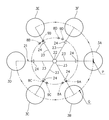
ドラム周回装置2は、指定した1つのケーブルドラム(3A〜3F)が正確にドラム使用位置Pあるいはドラム脱着位置Qで停止するように、その駆動量を制御する必要があるが、その制御は制御装置で行われる。尚、この実施例では、各ケーブルドラム3A〜3Fを、正周回方向(例えば左周回方向)と逆周回方向(例えば右周回方向)の両方向に周回させ、且つドラム使用位置Pとドラム脱着位置Qとの2箇所で停止させ得るようにしている関係で、大きく分けて4通りの制御が行われる。尚、各ケーブルドラムをドラム使用位置Pに移動させる際には、図1及び図2の状態において、3Bと3Cと3Dの各ケーブルドラムは左周回(正周回)移動し、3Eと3Fの各ケーブルドラムは右周回(逆周回)移動するようになっている。尚、3Aのケーブルドラムは不動である。又、各ケーブルドラムを図1及び図2の状態からドラム脱着位置Qに移動させる際(図4及び図5の状態)には、3Bと3Cと3Dの各ケーブルドラムは左周回(正周回)移動し、3Eと3Fと3Aの各ケーブルドラムは右周回(逆周回)移動するようになっている。
The
この制御装置には、1つの減速用検出器(8A〜8D)と1つの停止用検出器(9A〜9D)とを1組とする検出器セットを4セット使用している。即ち、この実施例では、図1〜図2、図4〜図5に示す各検出器(8A〜8D、9A〜9D)において、図6に示すように、8Aが正周回時(左周回時)においてドラム使用位置Pに停止させる際の減速用検出器、9Aが正周回時においてドラム使用位置Pに停止させる際の停止用検出器(8Aと9Aで1セット)、8Bが逆周回時(右周回時)においてドラム使用位置Pに停止させる際の減速用検出器、9Bが逆周回時においてドラム使用位置Pに停止させる際の停止用検出器(8Bと9Bで1セット)、8Cが正周回時においてドラム脱着位置Qに停止させる際の減速用検出器、9Cが正周回時においてドラム脱着位置Qに停止させる際の停止用検出器(8Cと9Cで1セット)、8Dが逆周回時においてドラム脱着位置Qに停止させる際の減速用検出器、9Dが逆周回時においてドラム脱着位置Qに停止させる際の停止用検出器(8Dと9Dで1セット)、である。
This control device uses four sets of detector sets, each of which includes one deceleration detector (8A to 8D) and one stop detector (9A to 9D). That is, in this embodiment, in each detector (8A to 8D, 9A to 9D) shown in FIGS. 1 to 2 and 4 to 5, as shown in FIG. ) When detecting at the drum use position P, when stopping at the drum use position P when 9A is rotating forward (one set of 8A and 9A), when 8B is rotating backward ( Deceleration detector for stopping at the drum use position P during right turn), Stop detector for stopping at the drum use position P when 9B is turning backward (one set of 8B and 9B), 8C for positive Deceleration detector when stopping at the drum attachment / detachment position Q during laps, Stop detector when stopping at the drum attachment / detachment position Q when 9C is rotating forward (one set of 8C and 9C), 8D during reverse laps Stop at the drum removal position Q Decelerating detectors, 9D reverse circulation stop detector when stopping the drum removable position Q at the time (8D and one
又、各1組の検出器セットは、回転体21の正逆各回転方向の上手側に減速用検出器(8A〜8D)が位置し、その下手側に停止用検出器(9A〜9D)が位置するように配置している。1組の検出器セット(減速用検出器と停止用検出器)の間隔は、回転方向に角度5°〜15°程度(図示例では10°)が適当である。尚、これらの検出器は、回転体21の外側面近傍の定位置に不動状態で取付けられており、回転体21が回転することによって、各アーム23,23・・に設けているカム24,24・・で順次操作されるようになっている。
Further, in each detector set, a deceleration detector (8A to 8D) is positioned on the upper side of each rotation direction of the
コントローラ61の操作部62には、図3に示すように、エンジンの作動・停止スイッチ63、呼出すケーブルドラムを選択するドラム選択スイッチ64A〜64F、ドラム停止位置選択スイッチ65、ケーブル繰出しスイッチ66、ケーブル巻取りスイッチ67、ドラム脱着切換スイッチ68、緊急停止スイッチ70等の各種スイッチ類が設けられている。
As shown in FIG. 3, the
又、この制御装置には、図6に示すように、各種スイッチで指定された内容に基いて所定のケーブルドラムを指定通りに制御するドラム周回制御手段6と、各検出器(8A〜8D、9A〜9Dの8個)のカウント数をそれぞれ個別に計数する合計8つのカウンター(減速用検出器カウンター78A〜78D、停止用検出器カウンター79A〜79D)と、後述するようにいずれか2つのカウンターの累積カウント数の差が「2」になるかどうかを判別する判別手段71と、回転体駆動装置25のモータ26を減速作動させる減速信号出力手段72と、該モータ26を停止させる停止信号出力手段73と、後述するように異常な検出器があったときにどの検出器が異常であるかを外部に報知するためのエラー報知手段7を有している。
Further, as shown in FIG. 6, the control device includes a drum circumference control means 6 for controlling a predetermined cable drum as specified based on the contents specified by various switches, and detectors (8A to 8D, A total of eight counters (deceleration detector counters 78A to 78D and stop
ドラム周回制御手段6は、ドラム停止位置選択スイッチ65でケーブルドラムを停止させる位置(ドラム使用位置Pかドラム脱着位置Q)を選択し、ドラム選択スイッチ64A〜64Fでどのケーブルドラム(3A〜3F)を呼出すかを選択すると、それらの選択条件に合った1組の検出器が機能する状態となり、その他の6個の検出器は操作されても(それぞれカウンターがカウントするが)目的とする制御に影響しないように設定されている。
The drum rotation control means 6 selects a position (drum use position P or drum attachment / detachment position Q) at which the cable drum is stopped by the drum stop
例えば、図1及び図2の状態から、3Dのケーブルドラムをドラム使用位置Pに呼出すには、ドラム停止位置選択スイッチ65(図3)でドラム使用位置を選択し、符号64Dのドラム選択スイッチを選択するが、そのとき符号8Aの減速用検出器(符号78Aの減速用検出器カウンター)と符号9Aの停止用検出器(符号79Aの停止用検出器カウンター)が機能する。そして、回転体駆動装置25のモータ26が正周回(左周回)作動をして、周回上手側の各カム24が減速用検出器8Aを3回操作した時点(3個目のカム24が減速用検出器8Aに到達した時点)でドラム周回制御手段6を介して減速信号出力手段72から減速信号が発せられてモータ26を減速作動させ、その後、同じく3個目のカム24が停止用検出器9Aを操作した時点でドラム周回制御手段6を介して停止信号出力手段73からモータ26停止信号が発せられてモータ26を停止させるようになる。このとき、指定した3Dのケーブルドラムは、正確にドラム使用位置Pで停止するようになる。
For example, in order to call a 3D cable drum to the drum usage position P from the state shown in FIGS. 1 and 2, the drum usage position is selected by the drum stop position selection switch 65 (FIG. 3), and the drum selection switch 64D is turned on. At that time, a
又、例えば、図1及び図2の状態から、3Fのケーブルドラムをドラム脱着位置Qに呼出すには、ドラム停止位置選択スイッチ65でドラム脱着位置を選択し、符号64Fのドラム選択スイッチを選択すると、符号8Dの減速用検出器(符号78Dの減速用検出器カウンター)と符号9Dの停止用検出器(符号79Dの停止用検出器カウンター)が機能する。そして、回転体駆動装置25のモータ26が逆周回(右周回)作動をして、周回上手側の各カム24が減速用検出器8Dを2回操作した時点(2個目のカム24が減速用検出器8Dに到達した時点)でモータ26を減速作動させ、その後、同じく2個目のカム24が停止用検出器9Dを操作した時点でモータ26を停止させるようになる。このとき、指定した3Fのケーブルドラムは、正確にドラム脱着位置Qで停止するようになる(図4及び図5の符号3Bの位置に3Fのケーブルドラムが位置する)。
Also, for example, in order to call the 3F cable drum to the drum attachment / detachment position Q from the state of FIGS. 1 and 2, the drum attachment / detachment position is selected by the drum stop
この制御装置では、上記のように、ケーブルドラムの呼出し位置(ドラム使用位置Pかドラム脱着位置Qか)及び呼出すケーブルドラムの初期位置によって、ケーブルドラムの周回方向と機能する1組の検出器セット(2つのカウンター)が決定され、それらの条件に基いて所望の動作が行われるようになっている。 In this control device, as described above, a set of detectors functioning with the direction of rotation of the cable drum depending on the calling position of the cable drum (whether it is the drum use position P or the drum removal position Q) and the initial position of the calling cable drum. (Two counters) are determined, and a desired operation is performed based on these conditions.
ところで、機能する1組の検出器セットのうち、停止用検出器(9A〜9D)に異常があると、減速用検出器(8A〜8D)が所定回数操作された時点で各ケーブルドラムが減速周回されるものの、周回し続けることになる。 By the way, if one of the functioning detector sets is abnormal in the stop detectors (9A to 9D), each cable drum decelerates when the deceleration detectors (8A to 8D) are operated a predetermined number of times. Although it goes around, it keeps going around.
そこで、この実施例の制御装置では、機能する1組の検出器セットのうち、いずれかの検出器に異常があると、次の手段により回転体駆動装置25のモータ26を強制停止させるようにしている。
Therefore, in the control device of this embodiment, when any one of the functioning detector sets is abnormal, the
即ち、この制御装置には、図6に示すように判別手段71を設けている。この判別手段71は、機能すべき1組の検出器セットの各検出器(例えば8Aの減速用検出器と9Aの停止用検出器)のカウント数を計数する各カウンター(例えば78Aの減速用検出器カウンターと79Aの停止用検出器カウンター)の累積カウント数の差が「2」以上になるか否かを判別し、その累積カウント数の差が「2」以上であると、停止信号出力手段73を作動させる(モータ26に停止信号を発する)機能を有している。 That is, the control device is provided with a discriminating means 71 as shown in FIG. This discriminating means 71 is provided with each counter (for example, 78A deceleration detection) for counting the number of counts of each detector (for example, 8A deceleration detector and 9A stop detector) to be functioned. A difference between the accumulated counts of the detector counter and the 79A stop detector counter) is “2” or more, and if the difference between the accumulated counts is “2” or more, the stop signal output means 73 (actuating a stop signal to the motor 26).
従って、1組の検出器セットのうちの1つの検出器が異常であると、各ケーブルドラム3A〜3F(各カム24)が2カウント分周回した時点で、異常検出器側のカウンターのカウント数が「0」であるのに対して、正常検出器側のカウンターのカウント数が「2」になり、その結果、各カウンターの累積カウント数の差が「2」になって、判別手段71が停止信号出力手段73を作動させる(停止信号を発する)ようになる。尚、停止信号出力手段73から停止信号が発せられると、回転体駆動装置25のモータ26を直ちに停止させる(各ケーブルドラムの周回が自動停止する)。
Therefore, if one of the detector sets is abnormal, each
このように、機能する検出器セットのうちのいずれかの検出器が異常である場合に、その異常に基いて回転体駆動装置25(モータ26)を強制停止させるようにすると、ケーブルドラムが周回し続けるというトラブルを未然に防止できる。 As described above, when any detector in the functioning detector set is abnormal, if the rotating body driving device 25 (motor 26) is forcibly stopped based on the abnormality, the cable drum rotates. The trouble of continuing to do so can be prevented in advance.
又、この実施例の制御装置では、機能すべき1組の検出器セットの両方が異常な状態でも、その異常な各検出器のカウンターの累積カウント数(「0」カウントのまま」)と他の正常な検出器のカウンターの累積カウント数との差が「2」以上になるか否かを判別手段71で判別して、該各累積カウント数の差が「2」になった時点で上記と同様に回転体駆動装置25のモータ26を直ちに停止させるようにしている。
Further, in the control device of this embodiment, even if both of the one set of detectors to function are in an abnormal state, the accumulated count number of each abnormal detector counter (“0” count ”) and others Whether the difference from the accumulated count of the normal detector counter becomes “2” or more is discriminated by the discriminating means 71, and when the difference between the accumulated counts becomes “2”, In the same manner as described above, the
さらに、この実施例の制御装置では、合計8つの検出器(8A〜8D、9A〜9D)のいずれかが(機能すべき検出器セット以外の検出器であっても)異常である場合にも、その異常検出器のカウンターの累積カウント数(「0」カウントのまま」)と他の正常な検出器のカウンターの累積カウント数との差が「2」以上になることで、上記判別手段71から判別信号が発せられるようにしている。 Furthermore, in the control device of this embodiment, even if any of the total of eight detectors (8A to 8D, 9A to 9D) is abnormal (even if it is a detector other than the detector set to function). When the difference between the cumulative count number of the counter of the abnormality detector (“0” count ”) and the cumulative count number of the counters of other normal detectors becomes“ 2 ”or more, the determination means 71 A discrimination signal is issued from
又、この実施例の制御装置には、いずれかの検出器に異常検出器がある場合に、その異常検出器を報知するエラー報知手段7を設けている。即ち、判別手段71が各カウンターの累積カウント数の差が「2」以上であると判別したしきに、該判別手段71から「0」カウントのままの検出器を識別する信号をエラー報知手段7に出力し、該エラー報知手段7で当該異常検出器を報知させるようになっている。
Further, the control device of this embodiment is provided with
このエラー報知手段7は、車輌1の適所(図1の例では側板13の外面)に設置している。又、このエラー報知手段7としては、例えば液晶表示部に異常検出器がどの検出器かを示すコード番号で表示させるものや、複数個(各検出器の数と同数)の表示灯を使用して異常検出器を点灯表示させるものや、音声でどの検出器が異常であるかを報知させるもの、等を採用できる。 This error notification means 7 is installed at an appropriate position of the vehicle 1 (in the example of FIG. 1, the outer surface of the side plate 13). As the error notification means 7, for example, a liquid crystal display unit that displays a code number indicating which detector is an abnormality detector or a plurality of indicator lights (the same number as each detector) is used. For example, an abnormality detector can be turned on and a voice can be used to notify which detector is abnormal.
このように、異常検出器があったときに、その異常検出器をエラー報知手段7で報知させるようにすると、保守作業時にどの検出器が異常であるかを捜す手間が不要となり、保守作業時間を短縮できる。 Thus, when there is an abnormality detector, when so as to notify the abnormality detector error notification means 7, what detector is abnormal among Investigation be hand becomes unnecessary at the time of maintenance work, maintenance Work time can be shortened.
又、この制御装置では、1セットとなる減速用検出器(例えば8A)と停止用検出器(例えば9A)において、減速用検出器8Aが異常である場合には、停止用検出器9Aの操作に基いて停止用検出器カウンター79Aが停止に必要なカウント数を計数しても、ドラム周回制御手段6から停止信号出力手段73に作動信号が出力されないようにしている。
Further, in this control device, when the
この理由は、図1及び図2において、例えば符号3Bのケーブルドラムをドラム使用位置Pに呼出すときのように、ケーブルドラム3Bの移動距離が1カウント分だけで停止用検出器9Aの停止用検出器カウンター79Aがカウントアップする場合には、ドラム周回制御手段6を介して停止信号出力手段73が停止信号を発し、判別手段71が作動することなく回転体駆動装置25(モータ26)が停止してしまうが、この場合はエラー報知手段7にエラー報知されなくなる。
The reason for this is that, in FIGS. 1 and 2, for example, when the cable drum 3B is called to the drum use position P, the stop detection of the
そこで、この制御装置では、減速用検出器(8A〜8D)が異常であるときには、指定したケーブルドラムが目的位置に近い場合(移動距離が1カウント分)であっても、ケーブルドラムが2カウント分だけ継続して周回するようにし(各カウンターの累積カウント数の差が「2」になる)、それによって判別手段71を作動させて、回転体駆動装置(モータ26)への停止機能とエラー報知手段7への異常検出器の報知機能とを生じさせるようにしている。 Therefore, in this control device, when the deceleration detector (8A to 8D) is abnormal, even if the designated cable drum is close to the target position (the moving distance is 1 count), the cable drum is counted 2 times. Circulate continuously for the number of minutes (the difference between the accumulated counts of the counters is “2”), thereby operating the discriminating means 71 to stop the rotating body drive device (motor 26) and the error. The function of notifying the abnormality detector to the notification means 7 is generated.
尚、上記実施例のケーブル延線車では、ドラム周回装置2として、各ケーブルドラム3A〜3Fを回転体21の各アーム23,23・・に装着して、該回転体21を回転させることで各ケーブルドラムを周回させるようにしたものを使用しているが、他の実施例では、ドラム周回装置2として、例えば実公平3−4095号公報に示されるようなチエーン駆動式のものを採用してもよい。
In the cable extension wheel of the above embodiment, as the
1は車輌、2はドラム周回装置、3A〜3Fはケーブルドラム、4はドラム駆動装置、5はドラム脱着装置、6はドラム周回制御手段、7はエラー報知手段、8A〜8Dは減速用検出器、9A〜9Dは停止用検出器、21は回転体、25は回転体駆動装置、61はコントローラ、62は操作部、64A〜64Fはドラム選択スイッチ、65はドラム停止位置選択スイッチ、71は判別手段、72は減速信号出力手段、73は停止信号出力手段、78A〜78Dは減速用検出器カウンター、79A〜79Dは停止用検出器カウンターである。 1 is a vehicle, 2 is a drum circulating device, 3A to 3F are cable drums, 4 is a drum driving device, 5 is a drum detaching device, 6 is a drum rotating control means, 7 is an error notification means, and 8A to 8D are deceleration detectors. , 9A to 9D are detectors for stopping, 21 is a rotating body, 25 is a rotating body driving device, 61 is a controller, 62 is an operation unit, 64A to 64F are drum selection switches, 65 is a drum stop position selection switch, and 71 is a discrimination. Means, 72 is a deceleration signal output means, 73 is a stop signal output means, 78A to 78D are deceleration detector counters, and 79A to 79D are stop detector counters.
Claims (5)
前記各ケーブルドラムが通過する度にその各ケーブルドラムの通過をそれぞれ検出する減速用検出器と停止用検出器とを1組とする検出器セットと、前記減速用検出器のカウント数を計数する減速用検出器カウンターと、前記停止用検出器のカウント数を計数する停止用検出器カウンターとを有し、指定した1つのケーブルドラムが前記ドラム使用位置まで移動する間に前記減速用検出器カウンターと前記停止用検出器カウンターがそれぞれカウントする回数に基いて前記ドラム周回装置を減速させた後に停止させるようにしたドラム周回制御手段を備えるとともに、
前記減速用検出器カウンターの累積カウント数と前記停止用検出器カウンターの累積カウント数との差が2以上になったときに判別信号を出力する判別手段を用いて、該判別手段が前記判別信号を出力したときに前記ドラム周回装置を停止させるようにしている、
ことを特徴とするケーブル延線車の制御装置。 In a cable extension vehicle that allows a plurality of cable drums to circulate synchronously by a drum circulator on the vehicle, and that the cable drum cable can be fed and wound at the drum use position,
Each time each cable drum passes, a detector set including a deceleration detector and a stop detector for detecting the passage of each cable drum, and the count number of the deceleration detector is counted. A deceleration detector counter and a stop detector counter for counting the count of the stop detector, and the deceleration detector counter while one designated cable drum moves to the drum use position And a drum rotation control means for stopping the drum rotation device after decelerating the drum rotation device based on the number of times each of the stop detector counters counts,
The discrimination means outputs a discrimination signal when the difference between the cumulative count number of the deceleration detector counter and the cumulative count number of the stop detector counter becomes 2 or more. The drum orbiting device is stopped when the
A control device for a cable-drawing vehicle characterized by that.
前記各ケーブルドラムが通過する度にその各ケーブルドラムの通過をそれぞれ検出する減速用検出器と停止用検出器とを1組とする検出器セットと、前記減速用検出器のカウント数を計数する減速用検出器カウンターと、前記停止用検出器のカウント数を計数する停止用検出器カウンターとを有し、指定した1つのケーブルドラムが前記ドラム脱着位置まで移動する間に前記減速用検出器カウンターと前記停止用検出器カウンターがそれぞれカウントする回数に基いて前記ドラム周回装置を減速させた後に停止させるようにしたドラム周回制御手段を備えるとともに、
前記減速用検出器カウンターの累積カウント数と前記停止用検出器カウンターの累積カウント数との差が2以上になったときに判別信号を出力する判別手段を用いて、該判別手段が前記判別信号を出力したときに前記ドラム周回装置を停止させるようにしている、
ことを特徴とするケーブル延線車の制御装置。 In a cable wire-drawing vehicle in which a plurality of cable drums circulate synchronously by a drum circulator on the vehicle, and the cable drum can be attached to or detached from the drum circulator at a drum detachment position.
Each time each cable drum passes, a detector set including a deceleration detector and a stop detector for detecting the passage of each cable drum, and the count number of the deceleration detector is counted. A deceleration detector counter and a stop detector counter for counting the count of the stop detector, and the deceleration detector counter while one designated cable drum moves to the drum attachment / detachment position And a drum rotation control means for stopping the drum rotation device after decelerating the drum rotation device based on the number of times each of the stop detector counters counts,
The discrimination means outputs a discrimination signal when the difference between the cumulative count number of the deceleration detector counter and the cumulative count number of the stop detector counter becomes 2 or more. The drum orbiting device is stopped when the
A control device for a cable-drawing vehicle characterized by that.
ドラム周回装置は、各ケーブルドラムを正逆両方向に周回させ得るようにして、指定したケーブルドラムを短い順路で目的位置まで移動させるようにしている一方、
減速用検出器と停止用検出器とを1組とする検出器セットを、ケーブルドラム正方向周回時に機能するものとケーブルドラム逆方向周回時に機能するものとの2セット使用している、
ことを特徴とするケーブル延線車の制御装置。 In claim 1 or 2,
While the drum circulating device allows each cable drum to circulate in both forward and reverse directions, the designated cable drum is moved to the target position in a short route,
Two sets of detector sets, one for decelerating detectors and one for stopping detectors, that function when the cable drum rotates in the forward direction and one that functions when the cable drum rotates in the reverse direction are used.
A control device for a cable-drawing vehicle characterized by that.
機能すべき1セットの減速用検出器及び停止用検出器のうち、ケーブルドラムが通過したにもかかわらずカウンターがカウントしない異常検出器がある場合に、その異常検出器を報知するエラー報知手段を設けている、
ことを特徴とするケーブル延線車の制御装置。 In any one of Claim 1 to 3,
Among a set of deceleration detectors and stop detectors that should function, when there is an abnormality detector that the counter does not count even though the cable drum has passed, error notification means that notifies the abnormality detector Provided,
A control device for a cable-drawing vehicle characterized by that.
1セットとなる減速用検出器と停止用検出器において、減速用検出器が正常に作動しないときは、停止用検出器カウンターが停止に必要なカウント数を計数しても停止用検出器によるドラム周回装置への停止信号が出力されないようにしている、
ことを特徴とするケーブル延線車の制御装置。 In claim 4,
In a set of deceleration detector and stop detector, if the deceleration detector does not operate normally, the stop detector counter counts the number of counts required for stop, and the drum by the stop detector The stop signal is not output to the orbiting device.
A control device for a cable-drawing vehicle characterized by that.
Priority Applications (1)
| Application Number | Priority Date | Filing Date | Title |
|---|---|---|---|
| JP2005076658A JP4336662B2 (en) | 2005-03-17 | 2005-03-17 | Control device for cable drawing car |
Applications Claiming Priority (1)
| Application Number | Priority Date | Filing Date | Title |
|---|---|---|---|
| JP2005076658A JP4336662B2 (en) | 2005-03-17 | 2005-03-17 | Control device for cable drawing car |
Publications (3)
| Publication Number | Publication Date |
|---|---|
| JP2006262624A JP2006262624A (en) | 2006-09-28 |
| JP2006262624A5 JP2006262624A5 (en) | 2008-03-27 |
| JP4336662B2 true JP4336662B2 (en) | 2009-09-30 |
Family
ID=37101238
Family Applications (1)
| Application Number | Title | Priority Date | Filing Date |
|---|---|---|---|
| JP2005076658A Expired - Fee Related JP4336662B2 (en) | 2005-03-17 | 2005-03-17 | Control device for cable drawing car |
Country Status (1)
| Country | Link |
|---|---|
| JP (1) | JP4336662B2 (en) |
Families Citing this family (1)
| Publication number | Priority date | Publication date | Assignee | Title |
|---|---|---|---|---|
| CN110416924B (en) * | 2019-07-09 | 2024-04-12 | 西南交通大学 | Subway tunnel construction railcar convenient to thread and tunnel cable threading method |
-
2005
- 2005-03-17 JP JP2005076658A patent/JP4336662B2/en not_active Expired - Fee Related
Also Published As
| Publication number | Publication date |
|---|---|
| JP2006262624A (en) | 2006-09-28 |
Similar Documents
| Publication | Publication Date | Title |
|---|---|---|
| JP4336662B2 (en) | Control device for cable drawing car | |
| JP7012972B2 (en) | Crane malfunction prevention system | |
| KR20190017839A (en) | High place working vehicles for agricultural industry | |
| EP0648701A1 (en) | Yarn winding machine | |
| JP4531197B2 (en) | Automatic tool changer | |
| CN212924224U (en) | Comprehensive protection device for blast furnace winding feeding system | |
| CN102807135B (en) | Monitoring display system and shuttle car | |
| JP5357861B2 (en) | Electric hoist | |
| EP1348551B1 (en) | Plate handling method and apparatus for printing press | |
| US20200377332A1 (en) | Elevator system, and method of preventing collisions between elevator cars | |
| CN203486774U (en) | Stretching angle detection system of superlift device | |
| JP6536789B2 (en) | Rope looseness detection device | |
| JP2006327708A (en) | Governor for elevator | |
| JP2583544B2 (en) | Cable winding abnormality detection device for rail machine | |
| JP5677672B2 (en) | Wheeled work machine | |
| CN107994835B (en) | Control method for servo incremental motor of tool magazine | |
| CN117003131A (en) | Wheel type mobile crane steel wire rope inlet and outlet alarm device and use method | |
| JPS5983811A (en) | Fault diagnostic device of hydraulic apparatus | |
| JPH08165070A (en) | Braking property monitoring device for elevator | |
| JP3189862B2 (en) | Working device detector diagnostic device | |
| JPH11179070A (en) | Hanging device | |
| KR200265063Y1 (en) | Wire fixing apparatus for hook crane | |
| CN220351583U (en) | Winch hoist and fault detection device thereof | |
| CN220793036U (en) | Lifting lamp with linear speed detection device | |
| JPS6347274A (en) | Abnormality monitoring method for cable reel |
Legal Events
| Date | Code | Title | Description |
|---|---|---|---|
| A521 | Request for written amendment filed |
Free format text: JAPANESE INTERMEDIATE CODE: A523 Effective date: 20080213 |
|
| A621 | Written request for application examination |
Free format text: JAPANESE INTERMEDIATE CODE: A621 Effective date: 20080213 |
|
| A977 | Report on retrieval |
Free format text: JAPANESE INTERMEDIATE CODE: A971007 Effective date: 20090528 |
|
| TRDD | Decision of grant or rejection written | ||
| A01 | Written decision to grant a patent or to grant a registration (utility model) |
Free format text: JAPANESE INTERMEDIATE CODE: A01 Effective date: 20090616 |
|
| A01 | Written decision to grant a patent or to grant a registration (utility model) |
Free format text: JAPANESE INTERMEDIATE CODE: A01 |
|
| A61 | First payment of annual fees (during grant procedure) |
Free format text: JAPANESE INTERMEDIATE CODE: A61 Effective date: 20090629 |
|
| FPAY | Renewal fee payment (event date is renewal date of database) |
Free format text: PAYMENT UNTIL: 20120703 Year of fee payment: 3 |
|
| R150 | Certificate of patent or registration of utility model |
Ref document number: 4336662 Country of ref document: JP Free format text: JAPANESE INTERMEDIATE CODE: R150 Free format text: JAPANESE INTERMEDIATE CODE: R150 |
|
| FPAY | Renewal fee payment (event date is renewal date of database) |
Free format text: PAYMENT UNTIL: 20130703 Year of fee payment: 4 |
|
| R250 | Receipt of annual fees |
Free format text: JAPANESE INTERMEDIATE CODE: R250 |
|
| R250 | Receipt of annual fees |
Free format text: JAPANESE INTERMEDIATE CODE: R250 |
|
| R250 | Receipt of annual fees |
Free format text: JAPANESE INTERMEDIATE CODE: R250 |
|
| R250 | Receipt of annual fees |
Free format text: JAPANESE INTERMEDIATE CODE: R250 |
|
| LAPS | Cancellation because of no payment of annual fees |