JP4335341B2 - Parts delivery device and parts delivery method - Google Patents
Parts delivery device and parts delivery method Download PDFInfo
- Publication number
- JP4335341B2 JP4335341B2 JP01552299A JP1552299A JP4335341B2 JP 4335341 B2 JP4335341 B2 JP 4335341B2 JP 01552299 A JP01552299 A JP 01552299A JP 1552299 A JP1552299 A JP 1552299A JP 4335341 B2 JP4335341 B2 JP 4335341B2
- Authority
- JP
- Japan
- Prior art keywords
- component
- guide shaft
- parts
- pressing member
- guide
- Prior art date
- Legal status (The legal status is an assumption and is not a legal conclusion. Google has not performed a legal analysis and makes no representation as to the accuracy of the status listed.)
- Expired - Fee Related
Links
Images


Classifications
-
- G—PHYSICS
- G07—CHECKING-DEVICES
- G07F—COIN-FREED OR LIKE APPARATUS
- G07F11/00—Coin-freed apparatus for dispensing, or the like, discrete articles
- G07F11/02—Coin-freed apparatus for dispensing, or the like, discrete articles from non-movable magazines
- G07F11/38—Coin-freed apparatus for dispensing, or the like, discrete articles from non-movable magazines in which the magazines are horizontal
- G07F11/42—Coin-freed apparatus for dispensing, or the like, discrete articles from non-movable magazines in which the magazines are horizontal the articles being delivered by motor-driven means
Description
【0001】
【発明の属する技術分野】
本発明は、自動販売物送り出し装置に関する。 本発明は多岐に渡り適用が可能であるが、基本的には自動販売機に適用されるものである。
【0002】
【従来の技術】
キーホルダ、ワッシャ、スクリュ・ナットといった類の部品は、装置内部から外へ制御により自動的に送り出すという形態をとるのが困難である。なぜならば、このような部品は、形、大きさが均一でないからである。すなわち、実質的には総合的に見たサイズ、形状、外形が類似していても、その差異により、各部品の間で量的に見た場合にわずかに差が生ずる。その部品の全体的な機能という点においては影響はないが、差異のある部品を装置から制御して送り出すのは困難だった。
それゆえ、例に挙げた類の部品は数量的にではなく、ひとかたまりとして生産、購入が行われ、通常、装置により販売する際には包装されないで装置外に送り出されるという形態をとっている。
【0003】
例えば、ペットの首輪に名札を取り付ける際に使われる、小さな環状の部品について上記のような問題が浮き彫りにされる。このような名札取付用の環状の部品を名札とセットで販売機により購入する場合、環状部品は包装されていない状態で販売機から出てくるようになっており、出てくる部品形状は不揃いとなる傾向がある。「部品形状が不揃いである」というのは、きれいな円形になっていない、外径と内径が部分部分で一致しない、部分部分で厚みが違っているといった状態を意味する。環状部品の形状が多少不揃いであっても実際その部品の機能を十分に果たすことはできる。
しかし、形状が不揃いであると自動販売機から、包装されない環状部品を外に正確に送り出すという動作に更なる支障をきたしていくことになる。
【0004】
【発明が解決しようとする課題】
例えば、ペットの名札に名前を彫って、名前を彫ったら販売機の中から外に送り出す形態の自動販売装置で名札を購入する場合、購入者はペット用名札一枚につき、ペットの首輪に名札を取り付けるためのリングを1個受け取ることになるのであるが、従来の自動販売機においてはそのリングが出てこないということが頻繁に起こった。
リングが販売機から出てこないので購入者はあせる、また名札を首輪に取り付けることが出来ないという問題があった。
確実に1個以上の一定の個数のリングを送り出すことのできる名札自動販売機がより好ましい。名札に取付用のリングがついてこなくては、購入者にとって名札を購入する根本的な目的を失ってしまうことになってしまうので、販売機は、リングが全然出てこないという事態が決して起こらないよう、作動したら確実に1個以上のリングが出てくるように設計すべきである。
【0005】
本発明は、形状が不揃いで包装されない部品を送り出すことができ、しかも確実に毎回作動するごとに1個以上の部品が出てくるように設計されている部品送り出し装置を提供することを目的とする。
【0006】
【課題を解決するための手段】
本発明の部品送り出し装置は、複数の部品を保持し、第一エンドと第二エンドを有するガイドシャフトと、前記ガイドシャフトに沿って移動することが可能な押圧部材と、前記押圧部材と係合する送りネジと、前記送りネジを回転させ、前記押圧部材を前記ガイドシャフトに沿って前記第二エンド方向に前進させ、それにより前記複数の部品を前記第二エンド方向に前進させるモータと、前記ガイドシャフトの前記第二エンドから1個の部品が送り出されたことを感知し、1個の部品が送り出されたことを感知するとただちに前記モータによる前記送りネジの駆動を停止させるセンサ・システムとからなるものである。
また、本発明の部品送り出し装置においては、前記センサ・システムはフォトセンサを含むこととするのが望ましい。
【0007】
また、本発明の部品送り出し装置においては、前記押圧部材は一部に雌ネジが形成されている解放レバーを有し、前記解放レバーは、前記雌ネジ部分が前記送りネジと係合する状態の第一ポジションと、前記の雌ネジ部分が前記送りネジと係合しなくなる状態の第二ポジションの間を移動可能であることが望ましい。また、本発明の部品送り出し装置においては、前記第一ポジション方向に前記解放レバーを傾ける手段を有することとするのが望ましい。
また、本発明の部品送り出し装置において、前記解放レバーは揺動できるように取り付けられており、前記解放レバーを前記第一ポジションの状態にするためにバネが配置されており、前記バネは前記解放レバーが前記第二ポジションまで揺動できる程度の強さの力が付与されると収縮する性質を有することとするのが望ましい。
【0008】
また、本発明の部品送り出し装置においては、少なくとも2本以上のガイドシャフトと、各ガイドシャフトに沿って移動が可能な少なくとも2個以上の押圧部材と、少なくとも2本以上の送りネジと、少なくとも2個以上のモータからなり、前記モータは連続的に順次、一連の各送りネジを駆動させるものでり、さらには、前記センサーは、第一モータが作動して一定の時間を経過しても部品が送り出されなかったことを感知すると、第一モータを停止させ、少なくとも2個以上あるモータのうちの1個を第一モータに続いて作動させるタイマ・サーキットを含むものであることが望ましい。
【0009】
また、本発明の部品送り出し装置は、さらにフレーム・アッセンブリを有し、前記フレーム・アッセンブリは、互いに対向する第一サイドプレート及び第二サイドプレートと、前記サイドプレートに接続され前記ガイドシャフトの前記第一エンドを支持するリア・ベアリング・プレートと、前記サイドプレートに接続され、前記リア・ベアリング・プレートとは間隔をおいて配置され、前記ガイドシャフトについて前記第一エンドと第二エンドの中間部分を支持するフロント・ベアリング・プレートからなり、前記リア、フロント・ベアリング・プレートは前記ガイドシャフトを片持ち梁の状態で支持していることとするのが望ましい。
【0010】
また、本発明の部品送り出し装置において、前記送りネジは、前記ガイドシャフトと平行に配置されており、第一エンド及び第二エンドを有し、前記第一エンドは前記リア・ベアリング・プレートによって支持され、前記ガイドシャフトは片持ち梁から突き出ている長さ分だけ前記押圧部材よって支持され、前記押圧部材は、前記ガイドシャフトに沿って移動することとするのが望ましい。
また、本発明の部品送り出し装置において、前記送りネジの第二エンドは前記リア・ベアリング・プレートから伸びており、前記押圧部材が前進して前記ガイドシャフトの前記第二エンドあるいはその近辺まで到達すると、前記押圧部材が前記送りネジと係合しなくなるようにするために、前記リア・ベアリング・プレートから同じく伸びているガイドシャフトの第二エンドよりも伸びている距離は短いこととするのが望ましい。
【0011】
また、本発明の部品送り出し装置はさらに、前記ガイドシャフトから送り出された部品を受け止め、前記センサ・システムが感知することができる位置まで前記送り出され部品を導く部品供給ユニットを備えることが望ましい。 また、本発明の部品送り出し装置において、前記部品供給ユニットは、前記ガイドシャフトの軸の延長上に少なくとも1個の開口部を有する第一プレートと、前記第一プレートとは間隔をおいて部品が落ちるときの通路を形成する第二プレートとを有し、前記開口部は装置より外に送り出すべき部品が通過することができる大きさであり、前記通路を経て部品は第一プレートの開口部を通り、前記部品は外に送り出されることとするのが望ましい。
【0012】
また、本発明の部品送り出し装置において、前記部品供給ユニットは、前記ガイドシャフトの第二エンドから送り出される部品を保持する前記ガイドシャフトの第二エンドに隣接していて部品が前記ガイドシャフトに保持される位置と、前記ガイドシャフトの第二エンドから間隔をおいて前記ガイドシャフトに部品を補給できるように部品を再蓄積する位置との間に、動かすことができるように取り付けられていることとするのが望ましい。
【0013】
また、本発明の部品送り出し装置はさらに、前記ガイドシャフトの前記第二エンド、あるいはその近辺に配置されたアイリスを有し、前記アイリスは、部品を通過させることができる開口部を有することとするのが望ましい。 また、本発明の部品送り出し装置において、前記アイリスは前記部品が通過できる開口部を有し、前記開口部は前記部品が通過することができる程度の複数のひだに取り囲まれており、前記開口部を通過するときに前記ひだにより部品の移動は一時食い止められることとするのが望ましい。
【0014】
あるいは本発明の部品送り出し装置は、複数の部品を保持するためのガイド部材と、装置外に送り出す部品を前記ガイド部材に沿って移動させる部品移動手段と、前記部品移動手段の移動度合いを大きくし、これにより前記ガイド部材に沿って前記複数の部品の前進の度合いが増す前進増加手段と、部品が前記ガイド部材から装置外に送り出されたことを感知し、部品が送り出されたことを感知するとただちに前記前進増加手段を停止させる手段とからなる。また、本発明の部品送り出し装置はさらに、前記複数の部品がガイド部材に沿って移動することを一時食い止め、これにより部品が1個ずつ装置外に送り出されることを容易にする手段を有することとするのが望ましい。
【0015】
また、本発明の部品送り出し装置において、前記前進増加手段には送りネジと前記送りネジを駆動させるモータとを含むこととするのが望ましい。
また、本発明の部品送り出し装置において、前記部品移動手段には前記ガイド部材に沿って移動可能な押圧部材を含み、前記押圧部材は選択的に前記送りネジと連動させることができることとするのが望ましい。
【0016】
あるいは本発明の部品送り出し装置は、複数の部品を保持し、第一エンド及び第二エンドを有するガイドシャフトと、前記ガイドシャフトに沿って移動可能な押圧部材と、前記ガイドシャフトの前記第二エンドに向かって前記複数の部品を前進させるために前記ガイドシャフトに沿って前記押圧部材の移動の度合いを増加させる移動増加手段と、前記ガイドシャフトの前記第二エンドの通り道に配置されるアイリスとからなるものであり、前記アイリスは前記部品が通過する動きを一時食い止めて、1回に1個の部品を制御により装置の外に送り出すことを容易にする。
または、本発明の部品送り出し装置は、前記アイリスは複数のひだに囲まれた開口部を有し、前記開口部は1個ずつ部品を通過させることとするのが望ましい。または、本発明の部品送り出し装置はさらに、1個の部品が前記アイリスを通過するとそれを感知することができるセンサー・システムを有し、前記センサー・システムは部品を感知するとただちに前記移動増加手段を停止させることとするのが望ましい。
【0017】
本発明における部品を保持する少なくとも1個のガイド部材を有する部品送り出し装置から部品を送り出す方法は、前記ガイド部材に沿って押圧部材を移動させ、前記押圧部材が移動することにより前記部品は前記ガイド部材の送り出しエンドに向かって部品を前進させる動作と、前記ガイド部材から部品が装置外に送り出されたことを感知する動作と、部品が送り出されたことを感知するとただちに前記押圧部材の動きを停止させる動作とによる。または、本発明における部品送り出し方法はさらに、部品は開口部を通過して前進するが、前記開口部が存在することにより前記ガイド部材から前記部品が送り出されるのを一時食い止めるという行程を含むこととするのが望ましい。
【0018】
【発明の実施の形態】
以下に本発明の好ましい実施の形態の詳細を適宜図面を参照して説明するものとする。なお、全ての図面を通じて同一あるは、類似する部品については極力同一の番号を付した。
【0019】
本発明に係る部品送り出し装置は、装置の外に送り出す複数の部品を保持するガイドシャフトを少なくとも1本以上備える。ガイドシャフトは第一エンド及び第二エンドを有する。
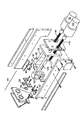
図1に本発明の好ましい実施の形態の概略を示す。図1には一対のガイドシャフト28及び128を有する部品送り出し装置が示されている。ガイドシャフト28及び128は図示されていない環状の部品を保持するためのものである。本実施例ではペットの首輪への名札取付用リングを対象としており、リングは、一例をあげれば、直径約0.5インチ、厚み約0.04インチである。そして、複数のリングがガイドシャフトの外周に連続して挿入されている。本実施例においては、環状の部品を貯めておけるようにするためにガイドシャフトの断面は円形になっている。ただし送り出される部品の形状、寸法や、装置内にストックしたいと思う部品の品目に応じて、本装置におけるガイドシャフトの数量及び形状は変更が可能である。 例えば方形の部品とその部品を挿入できるようなガイドシャフトの組合せも考えられる。
【0020】
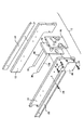
図2に示すように、本発明における部品送り出し装置はフロント・ベアリング・プレート18及びリア・ベアリング・プレート16の側面に沿って取り付けられる左右2枚のプレート12,14を含むフレーム・アッセンブリ10を有する。 サイド・プレート12,14及びベアリング・プレート16,18は、例えばネジ20で固定するものとするが、他に適当な固定用の部品があればそれによって固定してもよい。好ましくは、サイド・プレート12,14は一組のスライド・レール22に固定して、自動販売機の外側までレール付の本体をスライドさせて部品の補充が可能であるようにしたり、あるいはスライドさせて本体そのものを取り出し、別の自動販売機に入れ替えることが容易にできるようにすると良い。 また、ネジ24でサイド・プレート12,14をスライド・レール22に固定すると良い。
【0021】
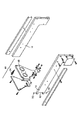
図2に示すように、リア・ベアリング・プレート16はガイドシャフト28及び128のリア・エンド26を支持し、フロント・ベアリング・プレート18の前方では、ガイドシャフト28及び128のフリー・エンド30が何の支持もなく、片持ち梁の状態で突き出ている。 ガイドシャフトのリア・エンド26は、圧入、接着、ネジなどどのような方法によりリア・ベアリング・プレート16に取り付けても構わない。
【0022】
本発明に係る部品送り出し装置は、相対するガイドシャフトに沿って移動可能な押圧部材を含む。 また本装置は押圧部材をより前方に押し進める手段も備え、押圧部材が押し進められることにより、ガイド部材上に保持されている複数の部品もより前方に押し進められていくのである。 ここに好ましい形態として示す実施例においては、前方に部材を押し進める手段は、送りネジと送りネジを駆動させるモータを含む。送りネジとモーターを組み合わせて使う以外にも、これに代わる制御により部材を押し進める方法は他にも考えられる。例えば、ベルトと滑車の組合せ、ギア・ヘッドと歯付ベルト駆動とスリップ・クラッチとの組合せ、ギア・ヘッドによる鎖駆動とスリップ・クラッチの組合せなどが考えられる。
【0023】
図1に示すように、部品送り出し装置は2個の押圧部材32及び132を備える。 そして2本の送りネジ40、140は押圧部材32、132とそれぞれ係合している。 押圧部材32、132をそれぞれガイドシャフト28、128に沿って押し進めるために、モータ50及び150は送りネジ40、140をそれぞれ回転駆動させる。そして押圧部材が前方押し進められることにより、ガイドシャフトの外周に連続的に挿入され蓄えられている複数の部品はガイドシャフトの第二エンドに向かって押し進められるのである
【0024】
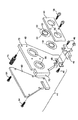
図3に示すように、各押圧部材32は円形開口部(上)34と、円形開口部(下)36と、円形開口部(下)36と円の中心を共有し、内周に雌ネジが形成された半円形カット部分35を有する解放レバー38とを含む。円形開口部(上)34の径はガイドシャフト28を受け止めることができる大きさであるが、わずかに公差精度がつけられている。これはシャフトの傾きが前と後で変わってしまうことなく部品を動かすためにある押圧部材32が滑りながら移動していくのを支えるためである。シャフトの傾きが変わらないようになっているので部品であるリングの端部表面がガイドシャフト28の軸に対して垂直に並ぶようできる。
円形開口部(下)36の径は、公差精度を考慮せず、おおまかに送りネジ40を受け止めることができる大きさである。送りネジ40は押圧部材32に受け止められている状態の時にはがっちりと解放レバー38と係合するようにされている。 解放レバー38は押圧部材32の最寄りのサイドプレートに隣接している方の側面の中間付近でその側面に対し垂直に収容されている。図3の押圧部材32の場合、左サイドプレート12に隣接する側面に解放レバー38は収容され、送りネジ40と係合するようになっている。
【0025】
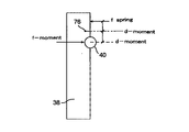
本発明に係る部品送り出し装置は好ましくは、押圧部材の内側に収容されている解放レバーと、解放レバーが揺れ動くことが出来るようにそれを押圧部材に取り付けるための揺動ピンと、解放レバーが送りネジによりかかっていくようにするために揺動ピンの周辺でモーメントが生じるように配置された圧縮バネとからなる負荷機構を含む。図3は本発明に係る実施例において、どのようにして押圧部材の中に収容されている解放レバー38が負荷機構を発揮するのかを簡単に示したものである。揺動ピン76により、解放レバー38は押圧部材32に取り付けられており、揺動ピンを中心に解放レバー38は揺動可能になっている。ネジ80により、圧縮バネ78が押圧部材32の内側にあるようにセットされ、新しいバネに取り替える必要がある場合には簡単に取り外しができるようになっている。図8に示すように、押圧部材32の内側にある圧縮バネ78は、解放レバー38のアームを押圧するモーメントを発生させ、解放レバー38が送りネジ40に寄りかかっていく仕組みを得るために配置されている。これにより、押圧部材32と送りネジ40とが係合できる。本発明に係る部品送り出し装置が作動している状態の時、ネジ80があるために圧縮バネ78は圧縮された状態になり、そのバネ78の圧縮による反発力で解放レバー38は揺動ピン76を中心に揺動し、送りネジ40と係合した状態となっている。
【0026】
図9は部品送り出し装置が、部品を購入者に渡すために部品を外に送り出す動作を行っている時、あるいは負荷モードにある時の状態を図示したものである。
手動で解放レバー38を押すと解放レバー38は揺動ピン76を中心に揺動し、送りネジ40から離れてしまいこれと係合しなくなる。係合しない状態にある時、押圧部材32をガイドシャフト28及び送りネジ40に沿って自由にガイドシャフト28のリア・エンド方向にスライドさせることが可能となり、販売用部品を新たにガイドシャフト28に補充できる。
【0027】
バネで解放レバー38に負荷をかける方法をとることにより、装置の故障によるダメージが避けられるというメリットも得られる。すなわち、故障が発生した場合、解放レバーは押圧部材の中から飛び出て送りネジとの係合から外れるように作られているのである。ここで、解放レバーの半円形35の内周に雌ネジが形成されいるのは圧縮ネジ78に加えられている予圧に打ち勝つようにするためである。したがって、故障の際のダメージを避けるためにセパレート・スリップ・クラッチを使う必要はなくなる。
【0028】
押圧部材32及び132の形状は同一である。解放レバーが送りネジとの係合から容易に外れるようにするために、もう一方の押圧部材132については、押圧部材32の上面37を通って垂直な軸(図3に図示)に対して180度回転させたポジションにするのが望ましい。こうすれば、押圧部材132の円形開口部(上)34と、円形開口部(下)36はそれぞれ第二ガイドシャフト128と第二送りネジ140を保持できる。
【0029】
図4,5に図示されるように、ガイドシャフト28及び128の真下に位置する送りネジ40,140はリア・ベアリング・プレート16により一方の端を支持されており、フロント・ベアリング・プレート18を通り押圧部材32及び132それぞれの円形開口部(下)36に保持されている。これに合わせて押圧部材32及び132がガイドシャフト28、128と一体となって動くのである。
【0030】
本発明に係る部品送り出し装置は、ガイドシャフトの第二エンドから装置の外に部品が押し出されたことを感知するためのセンサーシステムを有する。センサーシステムは部品が装置の外に押し出されたことを感知すると、送りネジを回転駆動させているモーターを停止させるようにするとよい。センサーシステムはガイドシャフトに貯めてある部品がなくなるまで正確に部品が1個押し出されるごとに押し出されたことを感知できるような位置に据え付けるようにする。本発明に係る部品送り出し装置は、さらに、平行に配置された2枚のプレートと、その2枚のプレートからなる部品供給ユニットとフレーム・アッセンブリをつなぎとめて部品供給ユニットが揺動できるようにするための揺動の中心(ピボット・ポイント)を有する取り外し可能な部品供給ユニットと、部品供給ユニットをフレーム・アッセンブリに対して固定・固定解除するためのラッチ機構とを備える。
部品供給ユニットの底部に配置されたセンサーが部品供給ユニットを通過する最後の1個まで全ての部品を容易に感知することができるように、部品供給ユニットを構成する平行に配置された前方及び後方プレートは低部が先細りになっていて、部品が落ちていく道(シュート・チャネル)が狭くなっている。
【0031】
図6を参照すると、本実施例における部品供給ユニット44はリア・プレート48とフロント・プレート62からなり、プレート間に平行な幅のスペースが取られており、ネジ64により互いのプレートは間をおいて取り付けられている。
しかし、例えばネジ以外のものを使ってもよい。リア・プレート48はアイリス52及び152を収容するための2つの円形開口部66と、センサーをはめ込むための切れ込み部68と、部品供給ユニット44にスペースを持たせるために同リア・プレートの他の部分よりも厚みがあるよう作られている垂直ヒンジ・ストリップ70と、フレームアッセンブリ10のサイドプレート12に対し部品供給ユニット44を安定させるためのローレットネジ74をはめこむための雌ネジが形成されている円形開口部73を有する。
【0032】
負荷あるいは装置が部品送り出しの動作を行う時の状況を容易に理解するために図7を参照されたい。図7において、部品供給ユニット44は異なる位置に動くことが可能である。対のピボットピン72により、部品供給ユニット44はサイドプレート14に取り付けられており、ピボットピン72を中心に部品供給ユニット44は揺動できるようになっている。サイド・プレート14先端、対のピボットピン72の間に窪み82が設けられており、そこにリア・プレート48の垂直ヒンジ・ストリップ70がはまる。本実施例におけるラッチ機構においてはローレットネジ74によって部品供給ユニット44をサイドプレート12にロックし、そして部品をガイドシャフトに補充する時、あるいは負荷を行う時に、部品供給ユニット44を動かせるように、ローレットネジ74は容易に抜けるようになっている。
【0033】
図6に示すように、本実施例においてはセンサー42が取り付けられている。
センサー42は、ガイドシャフト28及び128から部品が離れると重力によって落下していく際の通過地点である部品供給ユニット44の下部に位置する。
図6にある一対のボルト及びナット46によりセンサー42はリア・プレート48に固定されている。部品供給ユニット44は、低部が先細りになっていて、部品が落ちていく道(シュート・チャネル)が狭くなっている。そして部品供給ユニット44を通過していく部品はセンサー42の感知範囲を通過することになる。 本実施例においては、センサー42としてオムロン製モデルEES−X672、フォト・マイクロ・センサーを使用している。ただし他の感知システムの使用も可能であるし、確実に最後の1個まで部品がガイドシャフトから離れたことを感知できる位置であれば、センサーはどこに配置しても構わない。
【0034】
本発明に係る部品送り装置は、誤って部品が装置外に送り出されてしまうことを防止する手段と、ガイド部材に沿って複数の部品が前進する時に複数の部品のまとまりそのものの前進を物理的抵抗によって一時食い止めて、その物理的抵抗により、先頭にある部品のみ、1個ずつ通過させて装置外に送り出すことを容易にする手段とを有する。この手段として、弾性変形部材からなるアイリスを使用するとよい。より詳細には、アイリスの材料としては柔軟性プラスチック、例えばMylarなどを用いるとよい。ガイドシャフトの第二エンドに近接する位置にアイリスを配置するものとする。また、アイリスは開口部を有するが、制御により装置の外に送り出される部品が通過できる程度に開口部の大きさは取られている。 ガイドシャフトに連続的に保持されている複数の部品のまとまりは、まとまりごと押し進められると、アイリスをくぐって前進することになるが、アイリスの抵抗により、わずかの時間、部品のまとまりの前進は食い止められる。
すなわち、まとまりの先頭にある部品がアイリスの抵抗に逆らってその開口部を通過しようとするとき、アイリスは樹脂等の弾性変形部材で作られているため部品の進む方向に引っ張られる。ただしアイリスの開口部は部品が通過できる程度の大きさであるので、アイリスの抵抗を押し切って先頭の部品はアイリスを通過するが、その先頭の部品が通過する寸前までその部品の進行方向に引っ張られていたアイリスは、先頭の部品が通過すると即座に部品に引っ張られる前の状態に形状を回復し、次の部品の行く手に立ちはばかる。このような機構により、部品は1個ずつしか開口部を通過できないようになっているのである。このようにアイリスの前まで部品のまとまりが押し進められると、アイリスの開口部から部品は1個ずつくぐり抜けていくのである。また、万が一装置本体がひっくり返ったり、動かされたりしても、アイリスがあることによって部品はガイド部材に保持された状態に保たれ、誤って部品が装置外に送り出されることが防止されている。
【0035】
本実施例に係る形態は図6に示すように、アイリス52は部品が通過できるような円形状の開口部53を有し、その開口部の周囲には指のような形をした複数のひだ54が放射状にほどこされている。円形開口部53の直径は部品の外径より小さいものとなっている。アイリス52の柔軟性、硬直性はひだ54の数によって決まる。アイリス52の硬直性を高めるには、ひだ54の数を増やせばいい。 本実施例においては、12枚のひだ54を有するアイリス52が示されている。 部品を通すことができるひだ54は、開口部の中心に向かって伸びているが、ひだ54の先端に囲まれたアイリス開口部の内周の大きさは、送り出される部品の外周より小さい。 ただし、押し進められる先頭の部品1個が通過できる程度の大きさは取られており、先頭の次に控えている複数の部品はアイリス52の前で一時的に前進を遅らされるか、前進を食い止められるかされる。この点から見て、アイリスは部品送り出しを制御する機構として理想的な形で機能し、また、誤って部品が外に送り出されることを防ぐ機構としても機能する。
【0036】
あるいは、本発明に係る別の実施形態は、1個のモータを使って2個の押圧部材と送りネジの組合せを駆動させるものであってもよい。このような機構を容易に実現するには、互い違いに配置したアイリスを用いてそれぞれのガイド部材から部品が送り出される機構の代替方法とすればよい。本発明に係るセンサーを使用し、それぞれに対応するガイド部材に沿って外に送り出す部品の幅のほぼ二分の一分だけ間を取ってアイリスを配置し、それぞれのアイリスにより部品の前進を一時食い止めるようにすれば、本実施例で示すのとは別の形態で本実施例と同様に一組のガイド部材で部品を送り出すことが可能となる。
【0037】
図6に示すように、アイリス52はリア・プレート48内に収容され、リテーナ56で覆われているのが好ましい。 実際に使用されるアイリスの数と同数分、リア・プレート48とリテーナ56それぞれの円形開口部66と86を有する。 リア・プレート48とリテーナ56は確実にアイリス52と152を挟持し、それぞれ対応するガイドシャフト28及び128の軸に沿って並んでいる。 ネジ58、あるはこれに類似する留め具を用いて、リテーナ56をリア・プレート48に取り付けることができる。
【0038】
図1は、前述した各部材と部品送り出し装置の機構を示すものである。 モータ50はあらゆる周知の手段により駆動されるようになっている。例えば自動販売機に硬貨を入れる、あるいは自動販売機の制御システムから送られた命令信号によりモーターが駆動するという方法が考えられる。モータ50は送りネジ40を回転させ、それにより送りネジは回り出し、押圧部材32の内部で解放レバー38と係合する。その結果、押圧部材は前進し、ガイドシャフト28のフリーエンド30に向かって部品のまとまりを押していくのである。アイリス52は部品が1個ずつガイドシャフト28のフリーエンド30から離れていくように先頭以降の残りの部品の前進を押しとどめる役割を果たす。これは次回の作動で、フリーエンド30から離して装置外に送り出すべき部品が、現作動時にガイドシャフト28のフリーエンド30から即座に前進して離れ、誤って装置外に送り出されてしまわないように制御により抑制するためである。したがって、モータ50が送りネジ40を回転させると、アイリス52は先頭の次の部品が前進するのを遅らせるのである。そして先頭の部品はアイリス52をくぐり抜けて部品供給ユニットの中へ落ちていくのである。
【0039】
モータ50は駆動し続け、押圧部材32はセンサ42が1個の部品が押し出されたの感知するまで前進し続ける。このような仕組みにより、部品が全く装置の外に出てこないという事態の発生が減る。センサ42は1個の部品が部品供給ユニット44を通過してフリーエンド30から離れ落ちていくのを感知するごとに、モータ50に停止の信号を送る。モータ50のスピードは、装置が一度に部品を2個以上送り出してしまう事態が最小限に抑えられるようなスピードに調節されている。
【0040】
図2に示すように、当業者にとって周知のサーキット・カード・アッセンブリ88がネジ20でサイド・プレート14に取り付けられ、これが前述のロジカル・シーケンスを制御する。安全性を確保する機能として、サーキット・カード・アッセンブリ88は、センサ42を乗り越えた場所に配置され、硬貨が自動販売機に投入されるか、あるいは制御信号が部品を送り出す命令を出すといった動作のあった時点から一定時間経過後にモータ50を停止させるタイマを備えている。 この安全機構は、センサ42がうまく機能しない、あるいは部品が品切れになった場合に備えるものである。
【0041】
本実施例に示される本発明に係る部品送り出し装置は、前述した一連の部品送り出し動作を行うユニット2個から構成されている。それぞれのユニットは、好ましくは、1本のガイドシャフトと、1本の送りネジと、1個の押圧部材と、1個のアイリスと、1個のモータとから構成される。ここに開示する本発明では、販売するリングの種類の数に応じて、この一連部品送り出し動作を行うユニットを何個も搭載してもよい。
【0042】
図1及び4に示すように、本実施例に示す部品送り出し装置は、一連の部品送り出し動作を行うユニット2個から構成されている。 ユニットそれぞれは、ガイドシャフト28乃至128と、送りネジ40乃至140と、押圧部材30乃至130と、アイリス52乃至152と、モータ50乃至150とから構成される。 2個のユニット双方とも1つのフレーム・アッセンブリで囲まれ、一枚のリア・ベアリング・プレート16とフロント・ベアリング・プレート18により支持され、部品は全て部品供給ユニット44を通って装置の外に送り出される。押圧部材32と132の形状は同一であるが、各解放レバーの解除を容易に行えるように互いに180度対称にして配置されている。
【0043】
本発明に係る装置は、一連の部品送り出し動作を行うユニット1個以上で装置が構成されている場合の複数のユニットの作動を容易にするために、センサシステムの一部としてのタイマー・サーキットを有することが好ましい。 センサが一定時間内、例えば10秒以内に部品が装置の外に送り出されるのを感知しなかった場合、センサは、送り出し装置は次のユニットの作動へ体制に切り換えよという信号を送る。このように、停電、あるいは第一のユニット内の部品が品切れになるなどの支障が発生した場合に、システムは自動的に次に待機するユニットに作動の切り換えを行うようにしている。
【0044】
あるいは、本発明に係る部品送り出し装置は、一連の部品送り出し動作を行うように設計されたユニットに接続するリミット・スイッチ60を備えるものであってもよい。 図4は、部品送り出し装置の第一ユニットが作動する場合のリミット・スイッチ60を示しており、第一モータ50に接続されている。しかし、第一押圧部材32が第一ガイドシャフト28のフリーエンド30に到達すると、リミット・スイッチ60から第一モータ50へ電流は流れなくなり、第二モータ150に接続が切り替わり第二モータ150に電流が流れ、第二押圧部材132が第二ガイドシャフト128に沿って前進する動作を開始する。第二押圧部材132が第二ガイドシャフト128のフリーエンド30に到達したときには、販売部品全てが装置の外に送りだされていることになる。
【0045】
本実施例においては、部品送り出し装置にダメージを与えるようなことがないように設計されているのであれば、第二送りネジ40は、全ての部品が装置の外に送り出された後もなお回転するものであってもよい。この理由は、図5に示すように、送りネジ40はガイドシャフト28より短いものが好ましく、さらには送りネジ40は押圧部材32の円形開口部(下)36によって保持されるものが好ましいからである。図1の一般図に示される第二ユニットについても同様に、送りネジ140は第二ガイドシャフト128より短いのが好ましく、さらには送りネジ140は第二押圧部材132の円形開口部(下)36によって保持されるのが好ましい。このように第二押圧部材132が第二ガイドシャフト128のフリーエンド30に到達した時には、押圧部材132の内部での解放レバー38の背後、円形開口部(下)36のきわの部分で第二送りネジは保持されてはいるものの、第二送りネジ140のフロント・エンド41は第二押圧部材132の内部で解放レバー38とは係合しなくなる。したがって、部品送り出し装置の部品が無くなると、第二モータ150は動きはするものの第二送りネジ140は単に空回りするだけとなる。第二押圧部材132はリテーナ56を押圧せず、第二押圧部材132とリテーナ56の間に過度のストレスが発生することはない。
【0046】
【発明の効果】
本発明の請求項1に記載の部品送り出し装置によれば、ガイドシャフトを使用することにより、同一物でありながら形状、寸法などが若干不揃いで包装されないで販売する環状部品をガイドシャフトの外周に複数、連続的に保持することが可能となり、前記ガイドシャフトに沿って移動可能な押圧部材がモーターにより回転する送りネジと係合しているので、モーターの駆動は送りネジを介して連動関係にある押圧部材を確実に移動させ、押圧部材は移動する際にガイドシャフト外周に並んでいる複数の部品をまとまりごとガイドシャフトの第二エンド方向に押し進めることが可能となり、また押圧部材により第二エンドまで押し進められた複数の部品のまとまりは、やがてその先頭の1個が第二エンドから離れ、装置外に送り出されるとただちにセンサ・システムは送り出されたことを感知し、モーターの駆動を停止させ、モーターの停止に伴って送り出された先頭の部品の次に控える部品が続いて第二エンドから離れる前に押圧部材も部品を押し進めるのを停止するので、部品が余分に装置外に送りだされることなく1回の作動で形状が不揃いな部品を1個正確に送り出すことが可能である。
【0047】
また、本発明の請求項16に記載の部品送り出し装置によれば、ガイド部材を使用することにより、同一物でありながら形状、寸法などが若干不揃いで包装されないで販売する環状部品をガイド部材の外周に複数、連続的に保持することが可能となり、部品が保持されているガイド部材に沿って部品移動手段を搭載しているのでガイド部材に沿って部品を移動させることが可能であり、さらに前進増加手段を搭載しているのでガイド部材に沿って複数の部品がまとまりごと前進させることが可能となり、そして前進増加手段によりガイド部材の末端より部品が離れ、装置外に送り出されると部品が送り出されたことを感知し、複数の部品のまとまりを前進させる前進増加手段を停止させる部品感知および前進増加停止手段が搭載されているので部品が余分に装置外に送り出されることを防ぐことが可能である。
【0048】
さらに本発明の請求項20に記載の部品送り出し装置によれば、ガイドシャフトを使用することにより、同一物でありながら形状、寸法などが若干不揃いで包装されないで販売する環状部品をガイドシャフトの外周に複数、連続的に保持することが可能となり、部品が保持されているガイドシャフトに沿って押圧部材を搭載しているのでガイドシャフトに沿って部品を押し進めることが可能であり、そして移動増加手段を搭載しているので押圧部材により複数の部品がまとまりごとガイドシャフトに沿ってその第二エンド方向に移動させることが可能となり、さらに複数の部品のまとまりの先頭が第二エンドに達する手前にアイリスが配置されているので、先頭の部品が第二エンドに達するにはアイリスを通過しなければならないが、アイリスは複数の部品のまとまりの移動を一時的に食い止める程度の抵抗力を有しているため、部品は1個ずつしかアイリスを通過できず、このため、1回の作動で1個の部品を装置に送り出すことを確実かつ容易にし、また装置装置本体がひっくり返ったり動かされて正しく設置されていない状況でも誤って部品が装置外に送り出されるのを防ぐことが可能である。
【0049】
また、本発明の請求項23に記載の部品送り出し方法によれば、部品を保持するためのガイド部材を少なくとも1個備えている装置において、部品が保持されているガイド部材の送り出しエンド方向に押圧部材により部品を前進させると、送り出しエンドから離れて部品が装置外に送り出されたことを感知し、部品が送り出されたことを感知すると部品を前進させる押圧部材の動きを停止させるの機構を有するので1回の装置作動で部品1個確実に送り出すことが可能であり、また、部品が余分に装置外に送り出されるのを防ぐことが可能である。
【図面の簡単な説明】
【図1】本発明における部品送り出し装置の分解斜視図である。
【図2】 一対のガイドシャフトが取り付けられた状態での部品送り出し装置におけるフレームアッセンブリの分解斜視図である。
【図3】 押圧部材の分解斜視図である。
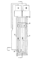
【図4】 部品送り出し装置を上から見た図(平面図)である。
【図5】 図4に示されている部品送り出し装置を部品破線I−Iに沿って切断した場合の断面図である。
【図6】 部品供給ユニットとこれにアイリスを取り付ける状態を説明するための分解斜視図である。
【図7】 部品供給ユニットこれにフレームアッセンブリを取り付ける状態を説明するための分解斜視図である。
【図8】 操作モード時に解放レバーが送りネジと係合している状態を示す正面図である。
【図9】 負荷モード時に解放レバーが送りネジとの係合から外れた状態を示す正面図である。
【符号の説明】
28、128 ガイドシャフト
10 フレーム・アッセンブリ
32、132 押圧部材
40、140 送りネジ
38 解放レバー38
44 部品供給ユニット
42 センサー
52,152 アイリス
50,150 モーター[0001]
BACKGROUND OF THE INVENTION
The present invention relates to a vending machine delivery apparatus. Although the present invention can be applied in various ways, it is basically applied to a vending machine.
[0002]
[Prior art]
Parts such as key holders, washers, screws and nuts are difficult to take out automatically from the inside of the apparatus by control. This is because such parts are not uniform in shape and size. That is, even if the size, shape, and outer shape seen from the overall viewpoint are similar, the difference causes a slight difference when viewed quantitatively between the parts. Although there was no impact on the overall function of the part, it was difficult to control and send out the different parts from the device.
Therefore, the parts of the kind mentioned in the example are not quantitatively produced but are produced and purchased as a whole and are usually sent out of the apparatus without being packaged when sold by the apparatus.
[0003]
For example, the above problems are highlighted for small annular parts used in attaching name tags to pet collars. When purchasing such a ring-shaped part for attaching a name tag together with a name tag from a vending machine, the ring-shaped part comes out of the vending machine without being packaged, and the shape of the parts that come out is not uniform. Tend to be. “Part shapes are irregular” means that the shape is not a beautiful circle, the outer diameter and the inner diameter do not coincide with each other, and the thickness is different between the parts. Even if the shape of the annular part is somewhat irregular, it can actually perform the function of the part sufficiently.
However, if the shape is not uniform, the vending machine will further hinder the operation of accurately feeding out the unwrapped annular part to the outside.
[0004]
[Problems to be solved by the invention]
For example, when a name tag is engraved on a pet name tag and the name tag is engraved and then sent out of the vending machine, the purchaser purchases the name tag on the pet collar for each pet name tag. One ring for attaching the ring will be received, but it often happens that the ring does not come out in the conventional vending machine.
Since the ring did not come out of the vending machine, there was a problem that the purchaser would be lost and the name tag could not be attached to the collar.
A name tag vending machine that can reliably deliver a certain number of rings of one or more is more preferable. If the name tag does not come with a mounting ring, the purchaser will lose the fundamental purpose of purchasing the name tag, so the vending machine will never have a ring at all. It should be designed to ensure that one or more rings emerge when activated.
[0005]
It is an object of the present invention to provide a component feeding device that can send out parts that are not shaped and are not wrapped, and that is designed so that one or more parts come out each time it operates reliably. To do.
[0006]
[Means for Solving the Problems]
The component delivery device of the present invention holds a plurality of components and has a guide shaft having a first end and a second end, a pressing member capable of moving along the guide shaft, and an engagement with the pressing member. A feed screw, a motor that rotates the feed screw, advances the pressing member in the second end direction along the guide shaft, and thereby advances the plurality of parts in the second end direction; From a sensor system that senses that one part has been delivered from the second end of the guide shaft, and that immediately stops sensing the delivery of one part from the motor. It will be.
In the component delivery device of the present invention, it is preferable that the sensor system includes a photosensor.
[0007]
In the component feeding device of the present invention, the pressing member has a release lever partially formed with a female screw, and the release lever is in a state where the female screw portion is engaged with the feed screw. It is desirable to be able to move between the first position and the second position where the female screw portion is not engaged with the feed screw. Moreover, in the component delivery apparatus of this invention, it is desirable to have a means to incline the release lever in the first position direction.
Further, in the component delivery device of the present invention, the release lever is attached so as to be able to swing, and a spring is disposed to bring the release lever into the first position, and the spring is the release lever. It is desirable that the lever has a property of contracting when a force strong enough to swing the lever to the second position is applied.
[0008]
In the component delivery device of the present invention, at least two or more guide shafts, at least two or more pressing members that can move along each guide shaft, at least two or more feed screws, and at least two The motor comprises a plurality of motors, and the motor drives a series of feed screws continuously and sequentially. Further, the sensor is a component even if a certain time has elapsed after the first motor is operated. It is desirable to include a timer circuit that stops the first motor when it is sensed that it has not been delivered and activates one of the at least two motors following the first motor.
[0009]
The component feeding device according to the present invention further includes a frame assembly, and the frame assembly is connected to the first side plate and the second side plate facing each other, and the first side plate of the guide shaft connected to the side plate. A rear bearing plate that supports one end, and is connected to the side plate, spaced from the rear bearing plate, and an intermediate portion between the first end and the second end with respect to the guide shaft. Preferably, the front and rear bearing plates support the guide shaft in a cantilevered state.
[0010]
In the component delivery device of the present invention, the feed screw is disposed in parallel with the guide shaft, and has a first end and a second end, and the first end is supported by the rear bearing plate. Preferably, the guide shaft is supported by the pressing member for a length protruding from the cantilever, and the pressing member moves along the guide shaft.
In the component feeding device of the present invention, the second end of the feed screw extends from the rear bearing plate, and the pressing member moves forward to reach the second end of the guide shaft or the vicinity thereof. In order to prevent the pressing member from engaging with the feed screw, it is desirable that the distance extending from the second end of the guide shaft that also extends from the rear bearing plate is shorter. .
[0011]
The component delivery device according to the present invention preferably further includes a component supply unit that receives the component delivered from the guide shaft and guides the delivered component to a position where the sensor system can sense the component. In the component delivery device of the present invention, the component supply unit includes a first plate having at least one opening on an extension of the shaft of the guide shaft, and the first plate having components spaced from each other. A second plate that forms a passage when falling, and the opening is sized to allow a part to be sent out of the apparatus to pass through, and the part passes through the opening of the first plate through the passage. As mentioned above, it is desirable that the parts are sent out.
[0012]
In the component delivery device of the present invention, the component supply unit is adjacent to the second end of the guide shaft that holds the component fed from the second end of the guide shaft, and the component is held by the guide shaft. It is attached so that it can be moved between the position where the part is stored and the position where the part is re-accumulated so that the part can be supplied to the guide shaft at a distance from the second end of the guide shaft. Is desirable.
[0013]
In addition, the component delivery device of the present invention further includes an iris arranged at or near the second end of the guide shaft, and the iris has an opening through which the component can pass. Is desirable. Further, in the component delivery device of the present invention, the iris has an opening through which the component can pass, and the opening is surrounded by a plurality of folds that allow the component to pass through. It is desirable that the movement of the parts is temporarily stopped by the pleats when passing through.
[0014]
Alternatively, the component delivery device of the present invention includes a guide member for holding a plurality of components, a component moving unit that moves the component to be fed out of the device along the guide member, and a degree of movement of the component moving unit. A forward increasing means for increasing the degree of advancement of the plurality of parts along the guide member, and detecting that the part has been sent out of the apparatus from the guide member, and detecting that the part has been sent out. And means for immediately stopping the forward increase means. The component delivery device of the present invention further includes means for temporarily stopping the movement of the plurality of components along the guide member, thereby facilitating the delivery of the components one by one to the outside of the device. It is desirable to do.
[0015]
In the component delivery device of the present invention, it is preferable that the advancement increasing means includes a feed screw and a motor for driving the feed screw.
In the component delivery device of the present invention, the component moving means may include a pressing member that can move along the guide member, and the pressing member can be selectively interlocked with the feed screw. desirable.
[0016]
Alternatively, the component delivery device of the present invention includes a guide shaft that holds a plurality of components and has a first end and a second end, a pressing member that can move along the guide shaft, and the second end of the guide shaft. A movement increasing means for increasing the degree of movement of the pressing member along the guide shaft in order to advance the plurality of parts toward the head, and an iris arranged on the path of the second end of the guide shaft. And the iris temporarily stops the movement of the parts and makes it easy to feed one part out of the device at a time.
Alternatively, in the component delivery device of the present invention, it is preferable that the iris has an opening surrounded by a plurality of pleats, and the opening allows the components to pass one by one. Alternatively, the component delivery device of the present invention further includes a sensor system capable of detecting when one component passes through the iris, and the sensor system includes the movement increasing means as soon as the component is detected. It is desirable to stop it.
[0017]
According to the present invention, there is provided a method for feeding a component from a component feeding device having at least one guide member for holding the component. The method includes moving the pressing member along the guide member, and moving the pressing member to move the component to the guide. The operation of advancing the component toward the delivery end of the member, the operation of sensing that the component has been fed out of the device from the guide member, and the movement of the pressing member are stopped immediately upon sensing that the component has been delivered. Depending on the action to be performed. Alternatively, the component feeding method according to the present invention further includes a step of temporarily stopping the component from being fed from the guide member due to the presence of the opening, although the component moves forward through the opening. It is desirable to do.
[0018]
DETAILED DESCRIPTION OF THE INVENTION
Details of preferred embodiments of the present invention will be described below with reference to the drawings as appropriate. Note that the same or similar parts are denoted by the same reference numerals throughout the drawings.
[0019]
The component delivery device according to the present invention includes at least one guide shaft that holds a plurality of components delivered to the outside of the device. The guide shaft has a first end and a second end.
FIG. 1 shows an outline of a preferred embodiment of the present invention. FIG. 1 shows a component feeding device having a pair of
[0020]
As shown in FIG. 2, the component feeding apparatus according to the present invention has a
[0021]
As shown in FIG. 2, the
[0022]
The component delivery device according to the present invention includes a pressing member that is movable along an opposing guide shaft. The apparatus also includes means for pushing the pressing member further forward, and when the pressing member is pushed forward, a plurality of parts held on the guide member are pushed forward further. In the preferred embodiment, the means for pushing the member forward includes a feed screw and a motor for driving the feed screw. In addition to using a feed screw and a motor in combination, other methods of pushing the member by using an alternative control are conceivable. For example, a combination of a belt and a pulley, a combination of a gear head, a toothed belt drive, and a slip clutch, a combination of a chain drive by a gear head, and a slip clutch can be considered.
[0023]
As shown in FIG. 1, the component feeding device includes two
[0024]
As shown in FIG. 3, each pressing
The diameter of the circular opening (lower) 36 is a size that can roughly receive the
[0025]
The component feeding device according to the present invention is preferably a release lever housed inside the pressing member, a swing pin for attaching the release lever to the pressing member so that the release lever can swing, and the release lever is a feed screw. In order to be applied, the load mechanism is composed of a compression spring arranged so that a moment is generated around the swing pin. FIG. 3 simply shows how the
[0026]
FIG. 9 illustrates a state in which the component delivery device is performing an operation of delivering a component to the purchaser, or is in a load mode.
When the
[0027]
By adopting a method of applying a load to the
[0028]
The shape of the
[0029]
As shown in FIGS. 4 and 5, the feed screws 40 and 140 located directly below the
[0030]
The component delivery device according to the present invention has a sensor system for detecting that a component has been pushed out of the device from the second end of the guide shaft. When the sensor system senses that the part has been pushed out of the device, the motor driving the lead screw in rotation may be stopped. The sensor system is installed in a position where it can be sensed that each part is pushed out until there is no part stored in the guide shaft. The component delivery device according to the present invention further includes two plates arranged in parallel, a component supply unit composed of the two plates, and a frame assembly so that the component supply unit can swing. A detachable component supply unit having a pivot point and a latch mechanism for fixing / unfixing the component supply unit to / from the frame assembly.
The front and rear of the component supply unit arranged in parallel so that the sensor arranged at the bottom of the component supply unit can easily sense all the components up to the last one passing through the component supply unit The plate is tapered at the bottom and the path (chute channel) through which the parts fall is narrow.
[0031]
Referring to FIG. 6, the
However, for example, other than screws may be used. The
[0032]
Refer to FIG. 7 for easy understanding of the situation when the load or the device performs the part feeding operation. In FIG. 7, the
[0033]
As shown in FIG. 6, a
The
The
[0034]
The component feeding device according to the present invention is a means for preventing parts from being accidentally sent out of the device, and physically moving the plurality of components together when the plurality of components advance along the guide member. It has a means for making it easy to temporarily stop by a resistor and to pass only one part at a head one by one and send it out of the device by its physical resistance. As this means, an iris made of an elastically deformable member may be used. More specifically, a flexible plastic such as Mylar may be used as the iris material. It is assumed that the iris is arranged at a position close to the second end of the guide shaft. The iris has an opening, but the opening is made large enough to allow parts to be sent out of the device to pass through the control. A group of parts continuously held on the guide shaft will advance through the iris when pushed together, but the resistance of the iris will prevent the part from moving forward for a short time. It is done.
That is, when the component at the head of the unit tries to pass through the opening against the resistance of the iris, the iris is made of an elastically deformable member such as a resin, so that the component is pulled in the advancing direction. However, since the opening of the iris is large enough to allow the part to pass through, the leading part passes through the iris by pushing out the resistance of the iris, but it is pulled in the direction of travel of the part until just before the leading part passes. As soon as the leading part has passed, the iris has recovered its shape to the state before being pulled by the part, and stands in the way of the next part. With this mechanism, only one part can pass through the opening. When the group of parts is pushed forward to the front of the iris in this way, the parts pass through one by one from the opening of the iris. Also, even if the main body of the device is turned over or moved, the presence of the iris keeps the component held by the guide member and prevents the component from being accidentally sent out of the device. Yes.
[0035]
As shown in FIG. 6, the embodiment according to this embodiment has a
[0036]
Alternatively, another embodiment according to the present invention may drive a combination of two pressing members and a feed screw using one motor. In order to easily realize such a mechanism, an alternative method may be used instead of a mechanism in which components are sent out from the respective guide members using irises arranged alternately. Using the sensor according to the present invention, the iris is arranged by taking about one half of the width of the part to be sent out along the corresponding guide member, and the advance of the part is temporarily stopped by each iris. If it does in this way, it will become possible to send out components with one set of guide members like this example in a form different from that shown in this example.
[0037]
As shown in FIG. 6, the
[0038]
FIG. 1 shows the above-described members and the mechanism of the component feeding device. The
[0039]
The
[0040]
As shown in FIG. 2, a
[0041]
The component delivery apparatus according to the present invention shown in this embodiment is composed of two units that perform the series of component delivery operations described above. Each unit is preferably composed of one guide shaft, one feed screw, one pressing member, one iris, and one motor. In the present invention disclosed herein, any number of units that perform this series of parts feeding operation may be mounted according to the number of types of rings to be sold.
[0042]
As shown in FIGS. 1 and 4, the component delivery apparatus shown in the present embodiment is composed of two units that perform a series of component delivery operations. Each unit includes
[0043]
The device according to the present invention has a timer circuit as a part of the sensor system in order to facilitate the operation of a plurality of units when the device is constituted by one or more units that perform a series of component feeding operations. It is preferable to have. If the sensor does not sense the part being delivered out of the device within a certain time, for example within 10 seconds, the sensor signals that the delivery device is ready to switch to operation of the next unit. As described above, when a failure such as a power failure or a part in the first unit runs out, the system automatically switches the operation to the next standby unit.
[0044]
Alternatively, the component delivery apparatus according to the present invention may include a
[0045]
In this embodiment, if it is designed so as not to damage the parts feeding device, the
[0046]
【The invention's effect】
According to the component delivery device of the first aspect of the present invention, by using the guide shaft, the annular component to be sold without being wrapped with the same shape, size, etc. is slightly uneven on the outer periphery of the guide shaft. Since a plurality of pressing members that can move continuously along the guide shaft are engaged with a feed screw that is rotated by a motor, the drive of the motor is linked via the feed screw. It is possible to move a certain pressing member with certainty, and when the pressing member moves, it is possible to push a plurality of parts arranged on the outer periphery of the guide shaft together in the direction toward the second end of the guide shaft, and the pressing member allows the second end to move. The group of parts pushed up to the end of time is that one of the heads will eventually leave the second end and be sent out of the device. The sensor system senses that it has been sent out, stops driving the motor, and presses the member before the part to be withdrawn next to the first part sent out as the motor stops and then leaves the second end. However, since the pushing of the parts is stopped, it is possible to accurately feed out one part whose shape is not uniform in one operation without extra parts being sent out of the apparatus.
[0047]
Further, according to the component delivery device of the sixteenth aspect of the present invention, by using the guide member, the annular component to be sold without being packaged because of the shape, size, etc., which is the same thing but slightly uneven, is provided. It is possible to continuously hold a plurality of pieces on the outer periphery, and since the component moving means is mounted along the guide member holding the component, the component can be moved along the guide member. Since the advancement increasing means is installed, a plurality of parts can be advanced together along the guide member, and the parts are separated from the end of the guide member by the advancement increasing means, and the parts are sent out when they are sent out of the device. It is equipped with component detection and forward increase stop means for detecting advancement and stopping forward increase means for advancing a group of multiple parts. It is possible to prevent the component is delivered to the outside of extra equipment.
[0048]
Furthermore, according to the component feeding apparatus of the present invention, the annular component to be sold without being wrapped with the same shape, size and the like is slightly uneven by using the guide shaft. It is possible to continuously hold a plurality of parts, and since the pressing member is mounted along the guide shaft on which the part is held, it is possible to push the part along the guide shaft and to increase the movement It is possible to move multiple parts together with the guide shaft along the guide shaft in the second end direction by the pressing member, and before the top of the multiple parts group reaches the second end Is placed, the leading part must pass through the iris to reach the second end, but the iris Has resistance enough to temporarily stop the movement of multiple parts, so only one part can pass through the iris, so one part can be installed in one operation. It is possible to reliably and easily send the component to the device, and to prevent parts from being mistakenly sent out of the device even when the device main body is turned over or moved and not properly installed.
[0049]
According to the component delivery method of the present invention, the device is provided with at least one guide member for holding the component, and is pressed toward the delivery end direction of the guide member holding the component. When the part is advanced by the member, it is sensed that the part is sent out of the apparatus away from the delivery end, and when the part is sensed that the part is sent out, the movement of the pressing member that advances the part is stopped. Therefore, it is possible to surely send out one part by one operation of the apparatus, and it is possible to prevent extra parts from being sent out of the apparatus.
[Brief description of the drawings]
FIG. 1 is an exploded perspective view of a component delivery device according to the present invention.
FIG. 2 is an exploded perspective view of a frame assembly in the component feeding device with a pair of guide shafts attached thereto.
FIG. 3 is an exploded perspective view of a pressing member.
FIG. 4 is a diagram (plan view) of the component delivery device as viewed from above.
5 is a cross-sectional view of the component delivery device shown in FIG. 4 cut along a component broken line II. FIG.
FIG. 6 is an exploded perspective view for explaining a component supply unit and a state in which an iris is attached to the component supply unit.
FIG. 7 is an exploded perspective view for explaining a state in which a frame assembly is attached to the component supply unit.
FIG. 8 is a front view showing a state in which the release lever is engaged with the feed screw in the operation mode.
FIG. 9 is a front view showing a state in which the release lever is disengaged from the feed screw in the load mode.
[Explanation of symbols]
28, 128 Guide shaft
10 Frame assembly
32, 132 Pressing member
40, 140 Lead screw
38
44 Parts supply unit
42 sensors
52,152 Iris
50,150 motor
Claims (21)
前記ガイドシャフトに沿って移動する可能な押圧部材と、
前記押圧部材と係合する送りネジと、
前記送りネジを回転させ、前記押圧部材を前記ガイドシャフトに沿って前記第二エンド方向に前進させ、それにより前記複数の部品を前記第二エンド方向に前進させるモータと、
前記ガイドシャフトの前記第二エンド、あるいはその近辺に配置されたアイリスと、
前記ガイドシャフトの前記第二エンドから1個の部品が送り出されたことを感知し、1個の部品が送り出されたことを感知するとただちに前記モーターによる前記送りネジの駆動を停止させるセンサ・システムとからなり、
前記アイリスは、部品を通過させることができる開口部を有することを特徴とする部品送り出し装置。 A plurality of parts products to retain, a guide shaft having a first end and a second end,
A push member which can you move along the front Symbol guide shaft,
A feed screw engaged with the pressing member;
A motor that rotates the feed screw, advances the pressing member in the second end direction along the guide shaft, and thereby advances the plurality of components in the second end direction;
The second end of the guide shaft, or an iris disposed in the vicinity thereof;
A sensor system that senses that one part has been delivered from the second end of the guide shaft, and that stops driving the feed screw by the motor upon sensing that one part has been delivered; Tona is,
The iris is the component feeding device you characterized by having an opening capable of passing parts.
前記センサ・システムはフォトセンサを含むことを特徴とする部品送り出し装置。The apparatus of claim 1.
The component delivery apparatus according to claim 1, wherein the sensor system includes a photosensor.
前記押圧部材は一部に雌ネジが形成されている解放レバーを有し、前記解放レバーは、前記雌ネジ部分が前記送りネジと係合する状態の第一ポジションと、前記の雌ネジ部分が前記送りネジと係合しなくなる状態の第二ポジションの間を移動可能であることを特徴とする部品送り出し装置。The apparatus of claim 1.
The pressing member has a release lever partially formed with a female screw, and the release lever has a first position in which the female screw portion is engaged with the feed screw, and the female screw portion is A component feeding device characterized in that the component feeding device is movable between a second position in a state where it is not engaged with the feed screw.
前記第一ポジション方向に前記解放レバーを付勢する手段を有することを特徴とする部品送り出し装置。The apparatus according to claim 3,
A component feeding device comprising means for urging the release lever in the first position direction.
前記解放レバーは揺動できるように取り付けられており、前記解放レバーを前記第一ポジションの状態にするためのバネが配置されており、前記バネは前記解放レバーが前記第二ポジションまで揺動できる程度の強さの力が付与されると収縮する性質を有することを特徴とする部品送り出し装置。The apparatus according to claim 3,
The release lever is attached so as to be able to swing, and a spring for placing the release lever in the state of the first position is arranged, and the spring can swing the release lever to the second position. A component feeding device characterized by having a property of contracting when a force of a certain degree of strength is applied.
少なくとも2本以上のガイドシャフトと、
各ガイドシャフトに沿って移動が可能な少なくとも2個以上の押圧部材と、
少なくとも2本以上の送りネジと、
少なくとも2個以上のモータからなり、
前記モータは連続的に順次、一連の各送りネジを駆動させることを特徴とする部品送り出し装置。The device according to claim 1 is:
At least two guide shafts;
At least two pressing members capable of moving along each guide shaft;
At least two lead screws;
Consisting of at least two motors,
The component feeding device according to claim 1, wherein the motor continuously and sequentially drives each of the feeding screws.
前記センサは、第一モータが作動して一定の時間を経過しても部品が送り出されなかったことを感知すると、第一モータを停止させ、少なくとも2個以上あるモーターのうちの1個を第一モータに続いて作動させるタイマ・サーキットを含むことを特徴とする部品送り出し装置。The apparatus according to claim 6.
When the sensor senses that the part has not been delivered even after a certain period of time has elapsed since the first motor was activated, the sensor stops the first motor, and at least one of the two or more motors is activated. A component feeding device comprising a timer circuit operated following one motor.
フレーム・アッセンブリを有し、
前記フレーム・アッセンブリは、
互いに対向する第一サイドプレート及び第二サイドプレートと、
前記サイドプレートに接続され前記ガイドシャフトの前記第一エンドを支持するリア・ベアリング・プレートと、
前記サイドプレートに接続され、前記リア・ベアリング・プレートとは間隔をおいて配置され、前記ガイドシャフトについて前記第一エンドと第二エンドの中間部分を支持するフロント・ベアリング・プレートとからなり、
前記リア、フロント・ベアリング・プレートは前記ガイドシャフトを片持ち梁の状態で支持していることを特徴とする部品送り出し装置。In the component delivery apparatus according to claim 1,
With a frame assembly,
The frame assembly is
A first side plate and a second side plate facing each other;
A rear bearing plate connected to the side plate and supporting the first end of the guide shaft;
A front bearing plate connected to the side plate, spaced apart from the rear bearing plate and supporting an intermediate portion of the first end and the second end of the guide shaft;
The rear and front bearing plates support the guide shaft in a cantilever state.
前記送りネジは、前記ガイドシャフトと平行に配置されており第一エンド及び第二エンドを有し、前記第一エンドは前記リア・ベアリング・プレートによって支持され、前記ガイドシャフトは片持ち梁から突き出ている長さ分だけ前記押圧部材によって支持され、前記押圧部材は、前記ガイドシャフトに沿って移動することを特徴とする部品送り出し装置。In the component delivery apparatus according to claim 8,
The feed screw is disposed parallel to the guide shaft and has a first end and a second end, the first end is supported by the rear bearing plate, and the guide shaft protrudes from the cantilever. The component feeding device is supported by the pressing member for a certain length, and the pressing member moves along the guide shaft.
前記送りネジの第二エンドは前記リア・ベアリング・プレートから伸びており、前記押圧部材が前進して前記ガイドシャフトの前記第二エンドあるいはその近辺まで到達すると、前記押圧部材が前記送りネジと係合しなくなるようにするために前記リア・ベアリング・プレートから同じく伸びているガイドシャフトの第二エンドよりも伸びている距離は短いことを特徴とする部品送り出し装置。In the component delivery apparatus according to claim 9,
The second end of the feed screw extends from the rear bearing plate. When the pressing member moves forward and reaches the second end of the guide shaft or the vicinity thereof, the pressing member is engaged with the feed screw. A component feeding device characterized in that the distance extending from the second end of the guide shaft, which also extends from the rear bearing plate, is short so as not to be aligned.
前記ガイドシャフトから送り出された部品を受け止め、前記センサ・システムが感知することができる位置まで前記送り出された部品を導く部品供給ユニットを備えることを特徴とする部品送り出し装置。In the component delivery apparatus according to claim 1,
A component delivery device comprising: a component supply unit that receives a component delivered from the guide shaft and guides the delivered component to a position that can be sensed by the sensor system.
前記部品供給ユニットは、
前記ガイドシャフトの軸の延長上に少なくとも1個の開口部を有する第一プレートと、
前記第一プレートとは間隔をおいて部品が落ちるときの通路を形成する第二プレートとを有し、
前記開口部は、装置より外に送り出すべき部品が通過することができる大きさであり、前記通路を経て部品は第一プレートの開口部を通り、前記部品は外に送り出されることを特徴とする部品送り出し装置。The apparatus of claim 11.
The component supply unit is
A first plate having at least one opening on an extension of the shaft of the guide shaft;
The first plate has a second plate that forms a passage when parts fall at an interval,
The opening is sized to allow a part to be sent out of the apparatus to pass through, the part passes through the opening of the first plate through the passage, and the part is sent out. Parts feeding device.
前記部品供給ユニットは、
前記ガイドシャフトの第二エンドから送り出される部品を保持する前記ガイドシャフトの第二エンドに隣接していて部品が前記ガイドシャフトに保持される位置と、前記ガイドシャフトの第二エンドから間隔をおいて前記ガイドシャフトに部品を補給できるように部品を再蓄積する位置との間に、動かすことができるように取り付けられていることを特徴とする部品送り出し装置。The apparatus according to claim 12, wherein
The component supply unit is
A position adjacent to the second end of the guide shaft that holds the component fed from the second end of the guide shaft and a position where the component is held by the guide shaft, and a distance from the second end of the guide shaft. A component feeding device, wherein the component feeding device is mounted so as to be movable between a position where components are re-accumulated so that components can be supplied to the guide shaft.
前記アイリスは前記部品が通過できる開口部を有し、前記開口部は前記部品が通過することができる程度の複数のひだに取り囲まれており、前記開口部を通過するときに前記ひだにより部品の移動は一時食い止められることを特徴とする部品送り出し装置。The apparatus of claim 1 .
The iris has an opening through which the part can pass, and the opening is surrounded by a plurality of pleats that allow the part to pass through. A parts feeding device characterized in that the movement is temporarily stopped.
装置外に送り出す部品を前記ガイド部材に沿って移動させる部品移動手段と、
前記部品移動手段の移動度合いを大きくし、これにより前記ガイド部材に沿って前記複数の部品の前進の度合いが増す前進増加手段と、
前記複数の部品がガイド部材に沿って移動することを一時食い止め、これにより部品が1個ずつ装置外に送り出されることを容易にする手段と、
部品が前記ガイド部材から装置外に送り出されたことを感知し、部品が送り出されたことを感知するとただちに前記前進増加手段を停止させる手段とからなる部品送り出し装置。 A guide member for hold a plurality of parts products,
And Parts for mobile unit Before moving the parts to leave feed in the instrumentation置外article along the guide member,
Advancement increasing means for increasing the degree of movement of the component moving means, thereby increasing the degree of advancement of the plurality of parts along the guide member;
Means for temporarily stopping the plurality of parts from moving along the guide member, thereby facilitating parts to be sent out of the apparatus one by one;
A component delivery device comprising: means for sensing that a component has been delivered from the guide member to the outside of the device; and means for stopping the advance increase means as soon as it senses that the component has been delivered.
前記前進増加手段には送りネジと前記送りネジを駆動させるモータを含むことを特徴とする部品送り出し装置。The apparatus according to claim 15 , wherein
2. The component feeding device according to claim 1, wherein the forward increasing means includes a feed screw and a motor for driving the feed screw.
前記部品移動手段には前記ガイド部材に沿って移動可能な押圧部材を含み、前記押圧部材は選択的に前記送りネジと連動させることができることを特徴とする部品送り出し装置。The apparatus according to claim 15 , wherein
The component moving means includes a pressing member movable along the guide member, and the pressing member can be selectively interlocked with the feed screw.
前記ガイドシャフトに沿って移動可能な押圧部材と、
前記ガイドシャフトの前記第二エンドに向かって前記複数の部品を前進させるために前記ガイドシャフトに沿って前記押圧部材の移動の度合いを増加させる移動増加手段と、
前記ガイドシャフトの前記第二エンドの通り道に配置されるアイリスとからなり、前記アイリスは前記部品が通過する動きを一時食い止めて、1回に1個の部品を制御により装置の外に送り出すことを容易にすることを特徴とする部品送り出し装置。 A plurality of parts products to retain, a guide shaft having a first end and a second end,
A pressing member movable along the front Symbol guide shaft,
Movement increasing means for increasing the degree of movement of the pressing member along the guide shaft to advance the plurality of parts toward the second end of the guide shaft ;
Consists of a pre-Symbol guide shaft wherein the second end of which is arranged in the path Rua Iris, the iris is halt temporarily move said part is over-through, out of the apparatus by controlling one component at a time A component delivery device characterized by facilitating delivery.
前記ガイド部材に沿って押圧部材を移動させ、前記押圧部材が移動することにより前記部品は前記ガイド部材の送り出しエンドに向かって部品を前進させる動作と、
部品は開口部を通過して前進するが、前記開口部が存在することにより前記ガイド部材から前記部品が送り出されるのを一時食い止める動作と、
前記ガイド部材から部品が装置外に送り出されたことを感知する動作と、
部品が送り出されたことを感知するとただちに前記押圧部材の動きを停止させる動作とにより、前記部品を装置外に送り出す部品送り出し方法。 The part article you hold, in the apparatus outside the part from the apparatus having at least one guide member,
Moving the pressing member along said guide member, said parts by the pressing member to move the operation to advance the feed Ri out part toward the end of the previous SL guide member,
The part moves forward through the opening, but the operation of temporarily stopping the part from being sent out from the guide member due to the presence of the opening;
An operation of sensing that a part has been sent out of the apparatus from the guide member;
A component delivery method for delivering the component to the outside of the apparatus by an operation of stopping the movement of the pressing member as soon as it senses that the component has been delivered.
Applications Claiming Priority (2)
| Application Number | Priority Date | Filing Date | Title |
|---|---|---|---|
| US09/013648 | 1998-01-26 | ||
| US09/013,648 US6082580A (en) | 1998-01-26 | 1998-01-26 | Article dispensing apparatus |
Publications (2)
| Publication Number | Publication Date |
|---|---|
| JPH11296735A JPH11296735A (en) | 1999-10-29 |
| JP4335341B2 true JP4335341B2 (en) | 2009-09-30 |
Family
ID=21761018
Family Applications (1)
| Application Number | Title | Priority Date | Filing Date |
|---|---|---|---|
| JP01552299A Expired - Fee Related JP4335341B2 (en) | 1998-01-26 | 1999-01-25 | Parts delivery device and parts delivery method |
Country Status (6)
| Country | Link |
|---|---|
| US (1) | US6082580A (en) |
| EP (1) | EP0932126A3 (en) |
| JP (1) | JP4335341B2 (en) |
| AU (1) | AU9811298A (en) |
| BR (1) | BR9900305A (en) |
| CA (1) | CA2260299C (en) |
Families Citing this family (22)
| Publication number | Priority date | Publication date | Assignee | Title |
|---|---|---|---|---|
| CZ9801U1 (en) * | 2000-02-08 | 2000-03-27 | Ondrej Szczotka | Packed products - especially drinks - vending machine |
| IT251040Y1 (en) * | 2000-08-10 | 2003-11-04 | Fas International Spa | PERFECTED DEVICE FOR THE EXPULSION OF A PRODUCT FROM AN AUTOMATIC DISTRIBUTOR. |
| US20040143506A1 (en) * | 2003-01-17 | 2004-07-22 | Goldman Robert P. | Method of selecting and digitally recording items to form a personalized compact disk |
| US7993088B2 (en) * | 2005-03-09 | 2011-08-09 | The Kroger Co. | Storage system having a dynamic support of moving elements and a pusher assembly carried by a frame |
| ITTO20040303A1 (en) * | 2004-05-10 | 2004-08-10 | Novarese Michele | REFINEMENTS IN AN AUTOMATIC ITEM DISTRIBUTOR |
| US7395945B2 (en) * | 2004-09-24 | 2008-07-08 | Nexiant | Controlled dispensing system with modular carousel |
| ITVI20050199A1 (en) * | 2005-07-18 | 2007-01-19 | Daint Srl | VENDING MACHINE |
| US9101990B2 (en) | 2006-01-23 | 2015-08-11 | Hy-Ko Products | Key duplication machine |
| EP1976656B1 (en) | 2006-01-23 | 2014-10-29 | Hy-Ko Products Company | Key duplication machine |
| US7353079B2 (en) * | 2006-02-02 | 2008-04-01 | William Rodriguez | Vending system for personalized pet collars and method therefor |
| US7882980B1 (en) * | 2008-07-15 | 2011-02-08 | Terry Horn | Sanitary lid dispenser |
| JP5324898B2 (en) * | 2008-12-02 | 2013-10-23 | サンデン株式会社 | Product vending machine for vending machines |
| MX343763B (en) | 2009-05-01 | 2016-11-18 | Hy-Ko Products | Key blank identification system with groove scanning. |
| EP2424690A4 (en) | 2009-05-01 | 2013-11-27 | Hy Ko Products | Key blank identification system with bitting analysis |
| CN103632441A (en) * | 2012-08-21 | 2014-03-12 | 鸿富锦精密工业(武汉)有限公司 | Regulating device |
| USD731203S1 (en) | 2013-11-20 | 2015-06-09 | Nse Products, Inc. | Fluid cartridge |
| USD733455S1 (en) | 2013-11-20 | 2015-07-07 | Nse Products, Inc. | Fluid cartridge assembly |
| USD731204S1 (en) | 2013-11-20 | 2015-06-09 | Nse Products, Inc. | Fluid cartridge |
| US10022741B2 (en) | 2014-08-22 | 2018-07-17 | Nse Products, Inc. | Selectively actuated fluid dispenser |
| US9818041B2 (en) | 2015-08-03 | 2017-11-14 | Hy-Ko Products Company | High security key scanning system |
| IT201900003287A1 (en) * | 2019-03-07 | 2019-06-07 | Sandenvendo Europe S P A | Product conveyor device for vending machines |
| CN111993828B (en) * | 2020-08-26 | 2022-03-29 | 惠州至精精密技术有限公司 | Cell-phone side key material feeding unit |
Family Cites Families (11)
| Publication number | Priority date | Publication date | Assignee | Title |
|---|---|---|---|---|
| FR1465474A (en) * | 1965-10-25 | 1967-01-13 | Cie Ind De Distributeurs Autom | Automatic bag dispenser device |
| US3901366A (en) * | 1973-10-09 | 1975-08-26 | Umc Ind | Vendor particularly for cartons of cigarettes or like packages |
| US3908859A (en) * | 1974-01-31 | 1975-09-30 | S J Agnew Agnew Environmental | Article dispensing apparatus |
| FR2267593A1 (en) * | 1974-04-10 | 1975-11-07 | Distribution Automatique Cie F | Vending machine for bags of sweets etc. - has screw shafts moving ejector plates to push bags to pivotal gates |
| US4236649A (en) * | 1979-04-06 | 1980-12-02 | Fellner N Van | Compact vending machine |
| JPS6048931U (en) * | 1983-09-12 | 1985-04-06 | アルプス電気株式会社 | Intermittent feed member |
| GB8907812D0 (en) * | 1989-04-06 | 1989-05-17 | Advanced Vending Services | Vending machine |
| DE4225165A1 (en) * | 1992-07-30 | 1994-02-03 | Trans Finanz Service Sa Luxemb | Vending machine |
| US5569003A (en) * | 1994-05-13 | 1996-10-29 | Quick-Tag, Inc. | Automated engraving apparatus and method |
| ITBS940060A1 (en) * | 1994-06-03 | 1995-12-03 | Roselli S R L Off Mec | AUTOMATIC DISTRIBUTOR OF NEWSPAPERS, MAGAZINES AND SIMILAR |
| US5813568A (en) * | 1996-03-29 | 1998-09-29 | Dpc International, Inc. | Dispensing machine for newspapers and magazines |
-
1998
- 1998-01-26 US US09/013,648 patent/US6082580A/en not_active Expired - Lifetime
- 1998-12-23 AU AU98112/98A patent/AU9811298A/en not_active Abandoned
-
1999
- 1999-01-04 EP EP99610001A patent/EP0932126A3/en not_active Withdrawn
- 1999-01-25 CA CA002260299A patent/CA2260299C/en not_active Expired - Lifetime
- 1999-01-25 JP JP01552299A patent/JP4335341B2/en not_active Expired - Fee Related
- 1999-01-26 BR BR9900305-8A patent/BR9900305A/en not_active Application Discontinuation
Also Published As
| Publication number | Publication date |
|---|---|
| JPH11296735A (en) | 1999-10-29 |
| AU9811298A (en) | 1999-08-12 |
| CA2260299A1 (en) | 1999-07-26 |
| BR9900305A (en) | 2000-02-22 |
| US6082580A (en) | 2000-07-04 |
| EP0932126A3 (en) | 2003-08-13 |
| CA2260299C (en) | 2004-11-02 |
| EP0932126A2 (en) | 1999-07-28 |
Similar Documents
| Publication | Publication Date | Title |
|---|---|---|
| JP4335341B2 (en) | Parts delivery device and parts delivery method | |
| US9741176B2 (en) | Lottery ticket dispensing device | |
| JPS61281385A (en) | Coin dumping apparatus | |
| US20080229892A1 (en) | Limiting device for roll printers | |
| KR20100105597A (en) | Multi-channel perforated ticket separation mechanism | |
| US4557169A (en) | Continuous tag cutting/feeding apparatus | |
| JP4422397B2 (en) | Ampoule storage container | |
| JP2563132B2 (en) | Device and machine for cutting wire ties | |
| KR101736859B1 (en) | Gift providing device for game machine | |
| US5082273A (en) | Slip storing apparatus | |
| JP4944556B2 (en) | Disc body ejector | |
| JPH03224764A (en) | Printing apparatus for continuous recording paper | |
| JP2585105B2 (en) | Electronic component supply device | |
| JPH0533491Y2 (en) | ||
| KR101842714B1 (en) | One-touch mounting type sticker feeder | |
| KR100380137B1 (en) | Machine for forming and taping a lead of a resistance | |
| JPH09311963A (en) | Coin throw-out device | |
| KR970006650B1 (en) | Automatic vending machine | |
| JP4007449B2 (en) | vending machine | |
| JPS6341334A (en) | Automatic paper feed machanism | |
| KR100890328B1 (en) | Series type ampoule dispensing device | |
| JP2919504B2 (en) | Vending machine for cup-type beverage vending machines | |
| JP2982650B2 (en) | Roller assembly equipment with shaft | |
| JP3983189B2 (en) | vending machine | |
| JP2002265078A (en) | Image forming apparatus having paper feed roller unit |
Legal Events
| Date | Code | Title | Description |
|---|---|---|---|
| A621 | Written request for application examination |
Free format text: JAPANESE INTERMEDIATE CODE: A621 Effective date: 20060123 |
|
| A711 | Notification of change in applicant |
Free format text: JAPANESE INTERMEDIATE CODE: A712 Effective date: 20060608 |
|
| A521 | Request for written amendment filed |
Free format text: JAPANESE INTERMEDIATE CODE: A821 Effective date: 20060612 |
|
| A521 | Request for written amendment filed |
Free format text: JAPANESE INTERMEDIATE CODE: A523 Effective date: 20061023 |
|
| A131 | Notification of reasons for refusal |
Free format text: JAPANESE INTERMEDIATE CODE: A131 Effective date: 20080520 |
|
| A601 | Written request for extension of time |
Free format text: JAPANESE INTERMEDIATE CODE: A601 Effective date: 20080805 |
|
| A602 | Written permission of extension of time |
Free format text: JAPANESE INTERMEDIATE CODE: A602 Effective date: 20080808 |
|
| A521 | Request for written amendment filed |
Free format text: JAPANESE INTERMEDIATE CODE: A523 Effective date: 20080905 |
|
| A131 | Notification of reasons for refusal |
Free format text: JAPANESE INTERMEDIATE CODE: A131 Effective date: 20081125 |
|
| A601 | Written request for extension of time |
Free format text: JAPANESE INTERMEDIATE CODE: A601 Effective date: 20090220 |
|
| A602 | Written permission of extension of time |
Free format text: JAPANESE INTERMEDIATE CODE: A602 Effective date: 20090225 |
|
| A521 | Request for written amendment filed |
Free format text: JAPANESE INTERMEDIATE CODE: A523 Effective date: 20090309 |
|
| TRDD | Decision of grant or rejection written | ||
| A01 | Written decision to grant a patent or to grant a registration (utility model) |
Free format text: JAPANESE INTERMEDIATE CODE: A01 Effective date: 20090602 |
|
| A01 | Written decision to grant a patent or to grant a registration (utility model) |
Free format text: JAPANESE INTERMEDIATE CODE: A01 |
|
| A61 | First payment of annual fees (during grant procedure) |
Free format text: JAPANESE INTERMEDIATE CODE: A61 Effective date: 20090625 |
|
| FPAY | Renewal fee payment (event date is renewal date of database) |
Free format text: PAYMENT UNTIL: 20120703 Year of fee payment: 3 |
|
| R150 | Certificate of patent or registration of utility model |
Free format text: JAPANESE INTERMEDIATE CODE: R150 |
|
| FPAY | Renewal fee payment (event date is renewal date of database) |
Free format text: PAYMENT UNTIL: 20120703 Year of fee payment: 3 |
|
| FPAY | Renewal fee payment (event date is renewal date of database) |
Free format text: PAYMENT UNTIL: 20130703 Year of fee payment: 4 |
|
| LAPS | Cancellation because of no payment of annual fees |