JP4335129B2 - Method and apparatus for specifying connection of devices on a data bus network - Google Patents
Method and apparatus for specifying connection of devices on a data bus network Download PDFInfo
- Publication number
- JP4335129B2 JP4335129B2 JP2004500503A JP2004500503A JP4335129B2 JP 4335129 B2 JP4335129 B2 JP 4335129B2 JP 2004500503 A JP2004500503 A JP 2004500503A JP 2004500503 A JP2004500503 A JP 2004500503A JP 4335129 B2 JP4335129 B2 JP 4335129B2
- Authority
- JP
- Japan
- Prior art keywords
- devices
- data bus
- peripheral devices
- input
- block
- Prior art date
- Legal status (The legal status is an assumption and is not a legal conclusion. Google has not performed a legal analysis and makes no representation as to the accuracy of the status listed.)
- Expired - Fee Related
Links
Images


Classifications
-
- G—PHYSICS
- G06—COMPUTING; CALCULATING OR COUNTING
- G06F—ELECTRIC DIGITAL DATA PROCESSING
- G06F13/00—Interconnection of, or transfer of information or other signals between, memories, input/output devices or central processing units
- G06F13/38—Information transfer, e.g. on bus
- G06F13/382—Information transfer, e.g. on bus using universal interface adapter
- G06F13/385—Information transfer, e.g. on bus using universal interface adapter for adaptation of a particular data processing system to different peripheral devices
-
- H—ELECTRICITY
- H04—ELECTRIC COMMUNICATION TECHNIQUE
- H04N—PICTORIAL COMMUNICATION, e.g. TELEVISION
- H04N5/00—Details of television systems
- H04N5/44—Receiver circuitry for the reception of television signals according to analogue transmission standards
-
- H—ELECTRICITY
- H04—ELECTRIC COMMUNICATION TECHNIQUE
- H04L—TRANSMISSION OF DIGITAL INFORMATION, e.g. TELEGRAPHIC COMMUNICATION
- H04L12/00—Data switching networks
- H04L12/28—Data switching networks characterised by path configuration, e.g. LAN [Local Area Networks] or WAN [Wide Area Networks]
- H04L12/40—Bus networks
- H04L12/40052—High-speed IEEE 1394 serial bus
- H04L12/40117—Interconnection of audio or video/imaging devices
-
- H—ELECTRICITY
- H04—ELECTRIC COMMUNICATION TECHNIQUE
- H04N—PICTORIAL COMMUNICATION, e.g. TELEVISION
- H04N21/00—Selective content distribution, e.g. interactive television or video on demand [VOD]
- H04N21/40—Client devices specifically adapted for the reception of or interaction with content, e.g. set-top-box [STB]; Operations thereof
- H04N21/43—Processing of content or additional data, e.g. demultiplexing additional data from a digital video stream; Elementary client operations, e.g. monitoring of home network or synchronising decoder's clock; Client middleware
- H04N21/436—Interfacing a local distribution network, e.g. communicating with another STB or one or more peripheral devices inside the home
- H04N21/43615—Interfacing a Home Network, e.g. for connecting the client to a plurality of peripherals
-
- H—ELECTRICITY
- H04—ELECTRIC COMMUNICATION TECHNIQUE
- H04N—PICTORIAL COMMUNICATION, e.g. TELEVISION
- H04N21/00—Selective content distribution, e.g. interactive television or video on demand [VOD]
- H04N21/40—Client devices specifically adapted for the reception of or interaction with content, e.g. set-top-box [STB]; Operations thereof
- H04N21/43—Processing of content or additional data, e.g. demultiplexing additional data from a digital video stream; Elementary client operations, e.g. monitoring of home network or synchronising decoder's clock; Client middleware
- H04N21/436—Interfacing a local distribution network, e.g. communicating with another STB or one or more peripheral devices inside the home
- H04N21/4363—Adapting the video or multiplex stream to a specific local network, e.g. a IEEE 1394 or Bluetooth® network
- H04N21/43632—Adapting the video or multiplex stream to a specific local network, e.g. a IEEE 1394 or Bluetooth® network involving a wired protocol, e.g. IEEE 1394
-
- H—ELECTRICITY
- H04—ELECTRIC COMMUNICATION TECHNIQUE
- H04N—PICTORIAL COMMUNICATION, e.g. TELEVISION
- H04N21/00—Selective content distribution, e.g. interactive television or video on demand [VOD]
- H04N21/40—Client devices specifically adapted for the reception of or interaction with content, e.g. set-top-box [STB]; Operations thereof
- H04N21/47—End-user applications
- H04N21/485—End-user interface for client configuration
-
- H—ELECTRICITY
- H04—ELECTRIC COMMUNICATION TECHNIQUE
- H04N—PICTORIAL COMMUNICATION, e.g. TELEVISION
- H04N5/00—Details of television systems
- H04N5/44—Receiver circuitry for the reception of television signals according to analogue transmission standards
- H04N5/445—Receiver circuitry for the reception of television signals according to analogue transmission standards for displaying additional information
-
- H—ELECTRICITY
- H04—ELECTRIC COMMUNICATION TECHNIQUE
- H04N—PICTORIAL COMMUNICATION, e.g. TELEVISION
- H04N5/00—Details of television systems
- H04N5/76—Television signal recording
- H04N5/765—Interface circuits between an apparatus for recording and another apparatus
-
- H—ELECTRICITY
- H04—ELECTRIC COMMUNICATION TECHNIQUE
- H04L—TRANSMISSION OF DIGITAL INFORMATION, e.g. TELEGRAPHIC COMMUNICATION
- H04L41/00—Arrangements for maintenance, administration or management of data switching networks, e.g. of packet switching networks
- H04L41/08—Configuration management of networks or network elements
-
- H—ELECTRICITY
- H04—ELECTRIC COMMUNICATION TECHNIQUE
- H04N—PICTORIAL COMMUNICATION, e.g. TELEVISION
- H04N21/00—Selective content distribution, e.g. interactive television or video on demand [VOD]
- H04N21/40—Client devices specifically adapted for the reception of or interaction with content, e.g. set-top-box [STB]; Operations thereof
- H04N21/41—Structure of client; Structure of client peripherals
- H04N21/426—Internal components of the client ; Characteristics thereof
-
- H—ELECTRICITY
- H04—ELECTRIC COMMUNICATION TECHNIQUE
- H04N—PICTORIAL COMMUNICATION, e.g. TELEVISION
- H04N5/00—Details of television systems
- H04N5/76—Television signal recording
- H04N5/765—Interface circuits between an apparatus for recording and another apparatus
- H04N5/775—Interface circuits between an apparatus for recording and another apparatus between a recording apparatus and a television receiver
Landscapes
- Engineering & Computer Science (AREA)
- Multimedia (AREA)
- Signal Processing (AREA)
- Computer Networks & Wireless Communication (AREA)
- Theoretical Computer Science (AREA)
- Human Computer Interaction (AREA)
- Physics & Mathematics (AREA)
- General Engineering & Computer Science (AREA)
- General Physics & Mathematics (AREA)
- Two-Way Televisions, Distribution Of Moving Picture Or The Like (AREA)
- User Interface Of Digital Computer (AREA)
Description
本出願は、2002年4月24日に米国特許庁に出願された2つの仮出願第60/375,136号及び第60/375,207号に対する優先権及びこれらから生じるあらゆる効果を主張するものである。 This application claims priority to two provisional applications Nos. 60 / 375,136 and 60 / 375,207 filed with the US Patent Office on April 24, 2002, and any effects resulting therefrom. It is.
発明の背景
[発明の技術分野]
本発明は、一般に映像信号処理装置及び映像信号処理装置の制御方法に関し、より詳細には、当該装置にデジタルデータバスネットワーク接続を介し接続される複数の周辺装置と複数のアナログ入力に対する補助的なアナログ接続のユーザによる効率的かつ容易な指定を可能にする装置及び方法に関する。
[関連技術]
テレビ信号受信機、パーソナルコンピュータ、表示装置、映像カセットレコーダ(VCR)、DVD(Digital Versatile Disk)プレーヤー、DBS(Direct Broadcast Satellite)受信機、住宅制御装置(例えば、スきゅうりティシステム、温度制御装置など)及び/または他の装置などの電子装置を相互接続するデータバスが利用可能である。データバスを利用した通信は、典型的には、指定されたバスプロトコルに従って行われる。そのようなバスプロトコルの例としては、当該分野において周知のIEEE(Institute for Electrical and Electronic Engineers)1394高性能シリアルバスプロトコル(IEEE1394またはFirewire(登録商標))があげられる。
BACKGROUND OF THE INVENTION [Technical Field of the Invention]
The present invention relates generally to a video signal processing device and a control method for the video signal processing device, and more particularly, to a plurality of peripheral devices connected to the device via a digital data bus network connection and a plurality of analog inputs. The present invention relates to an apparatus and method that enable efficient and easy designation by a user of an analog connection.
[Related technologies]
TV signal receiver, personal computer, display device, video cassette recorder (VCR), DVD (Digital Versatile Disk) player, DBS (Direct Broadcast Satellite) receiver, housing control device (eg, cucumber system, temperature control device, etc.) And / or data buses that interconnect electronic devices such as other devices are available. Communication using the data bus is typically performed according to a designated bus protocol. An example of such a bus protocol is the IEEE (Institute for Electrical and Electronic Engineers) 1394 high performance serial bus protocol (IEEE 1394 or Firewire (registered trademark)), which is well known in the art.
IEEE1394ネットワークのようなネットワークでは、複数の装置が相互接続され、ネットワークを介して音声及び/または映像データなどのデータのやりとりが装置間において可能である。さらに、ユーザが、ネットワーク上の装置を当該ネットワーク上の他の装置を介して制御するようにしてもよい。このため、IEEE1394ネットワークのようなネットワークは、当該ネットワークに接続される装置間での互換性を提供する。IEEE1394はまた、デイジーチェーン方式で接続される多数の(例えば、63台までの)相互接続された装置を収容することができる。 In a network such as an IEEE 1394 network, a plurality of devices are interconnected, and data such as audio and / or video data can be exchanged between the devices via the network. Furthermore, the user may control a device on the network via another device on the network. For this reason, a network such as an IEEE 1394 network provides compatibility between devices connected to the network. IEEE 1394 can also accommodate multiple (eg, up to 63) interconnected devices connected in a daisy chain fashion.
EIA(Electronics Industories Association)775は、IEEE1394バスを介した対象装置への送信元装置によるデータ(例えば、画面表示データ、音声/映像データなど)の送信方法を記載した規格である。特に、EIA775は、送信元装置の中には、MPEG(Motion Picture Expert Group)映像データなどのデジタルデータと共にアナログデータの送信が可能なものがあるという事実を認めている。例えば、あるセットトップボックスは、ATSC(
Advanced Television Standards Committee)信号などのデジタル信号と共に、NTSC(National Television Standards Committee)信号などのアナログ信号の送受信が可能である。そのような装置を受け入れるため、EIA775によると、送信元装置が送信先装置に送信先装置への送信信号がデジタルまたはアナログであるか通知することができる。従って、送信先装置がこの情報を受け取ると、当該信号がデジタルの場合にはその入力信号は例えば、IEEE1394入力コネクタにスイッチされ、当該信号がアナログである場合にはそれのアナログ入力コネクタの1つにスイッチすることができる。
EIA (Electronics Industries Association) 775 is a standard that describes a method of transmitting data (for example, screen display data, audio / video data, etc.) by the transmission source device to the target device via the IEEE 1394 bus. In particular, EIA 775 acknowledges the fact that some source devices are capable of transmitting analog data along with digital data such as MPEG (Motion Picture Expert Group) video data. For example, some set-top boxes have ATSC (
Analog signals such as NTSC (National Television Standards Committee) signals can be transmitted and received together with digital signals such as Advanced Television Standards Committee (Advanced Television Standards Committee) signals. To accept such a device, according to EIA 775, the source device can inform the destination device whether the transmission signal to the destination device is digital or analog. Thus, when the destination device receives this information, the input signal is switched to, for example, an IEEE 1394 input connector if the signal is digital, and one of its analog input connectors if the signal is analog. Can be switched to.
従来の装置によると、ユーザは、指定した送信元装置を送信先装置の与えられたアナログ入力端末に接続することを指示するため、この潜在的な送信先装置とやりとりする。例えば、このやりとりは、新たな送信元装置を送信先装置に接続するとき、あるいは送信先装置の設定表示のユーザによる選択に応答して行われるかもしれない。しかしながら運の悪いことに、このような従来の装置では、このタイプのやりとりは装置単位でのみ利用可能である。すなわち、従来の装置は、送信先装置に接続されるすべての送信元装置と、当該送信先装置に関するすべての可能なアナログ入力を示す単一の画面を提供するものではない。代わりに、ユーザは、送信先装置への接続を指定するため、複数の画面(例えば、送信元装置毎に1画面)をナビゲートすることが求められる。これは、装置の接続を指定するのに多くの異なる画面をナビゲートする必要あるため、ユーザにとって不便かつ時間のかかる作業となる。さらに、装置接続を指定するため複数の画面を利用することは、ユーザが複数の画面をナビゲートするとき、ユーザは様々な送信元装置と送信先装置上の接続を精神的に追跡しなければならないため問題となりうる。 According to the conventional device, the user interacts with this potential destination device to instruct to connect the designated source device to the given analog input terminal of the destination device. For example, this exchange may occur when a new source device is connected to the destination device or in response to a user selection of a destination device setting display. Unfortunately, however, this type of interaction is only available on a device basis in such conventional devices. That is, conventional devices do not provide a single screen showing all source devices connected to a destination device and all possible analog inputs for the destination device. Instead, the user is required to navigate multiple screens (eg, one screen for each source device) to specify a connection to the destination device. This is inconvenient and time consuming for the user because it is necessary to navigate many different screens to specify the connection of the device. Furthermore, using multiple screens to specify device connections means that when a user navigates through multiple screens, the user must mentally track the connections on the various source devices and destination devices. It can be a problem because it does not.
従って、前述の問題点を回避し、IEEE1394ネットワークのようなデータバスネットワーク上の装置に対するアナログ接続のより便利かつ時間効率的なユーザによる指定を可能にする装置及び方法が必要とされる。
[発明の概要]
本発明の一特徴によると、デジタルデータバスネットワークに接続される装置の制御方法が開示される。一実施例によると、本方法は、各自がデジタル出力とアナログ出力を有する複数の周辺装置に前記映像信号処理装置を接続するステップと、前記映像信号処理装置に接続されている前記複数の周辺装置のリストと前記映像信号処理装置のアナログ入力のリストを有する画面表示を提供するステップと、前記画面表示上のユーザ選択に応答して、前記複数の周辺装置の選択された周辺装置のアナログ出力と選択されたアナログ入力を関連付けるステップとからなり、前記映像信号処理装置は、デジタルデータバスネットワーク接続を介し前記複数の周辺装置のデジタル出力に接続され、前記映像信号処理装置の各アナログ入力を介し前記複数の周辺装置の各アナログ出力に接続されることを特徴とする。
Accordingly, there is a need for an apparatus and method that avoids the aforementioned problems and allows more convenient and time efficient user designation of analog connections to devices on a data bus network such as an IEEE 1394 network.
[Summary of Invention]
According to one aspect of the present invention, a method for controlling a device connected to a digital data bus network is disclosed. According to one embodiment, the method includes connecting the video signal processing device to a plurality of peripheral devices each having a digital output and an analog output, and the plurality of peripheral devices connected to the video signal processing device. Providing a screen display having a list of and a list of analog inputs of the video signal processing device; and analog outputs of selected peripheral devices of the plurality of peripheral devices in response to a user selection on the screen display; Associating a selected analog input, wherein the video signal processing device is connected to digital outputs of the plurality of peripheral devices via a digital data bus network connection, and the video signal processing device is connected via the analog inputs of the video signal processing device. It is connected to each analog output of a plurality of peripheral devices.
本発明の他の特徴によると、上記方法を実行するよう動作する電子装置が開示される。一実施例によると、本電子装置は、デジタルデータバス接続と、各自がデジタル出力とアナログ出力を有する複数の周辺装置に該映像信号処理装置を接続するための複数のアナログ入力とを有する入出力手段と、ユーザ入力の受信手段と、画面表示の生成手段と、前記デジタルデータバス接続と前記複数のアナログ入力に接続され、受信した映像信号を処理し、表示に適した出力信号を提供する処理手段と、前記出力信号を表示装置に接続する手段とからなり、前記複数の周辺装置のデジタル出力は前記デジタルデータバスネットワーク接続を介し該映像信号処理装置に接続され、前記複数の周辺装置のアナログ出力は該映像信号処理装置の各アナログ入力を介し該映像信号処理装置に接続され、前記生成手段は、該映像信号処理装置に接続されている前記複数の周辺装置のリストと該映像信号処理装置の前記複数のアナログ入力のリストを有する画面表示を提供し、前記処理手段は、前記画面表示上のユーザ選択に応答して、前記複数の周辺装置の選択された周辺装置のアナログ出力と選択されたアナログ入力を関連付けることを特徴とする。 According to another aspect of the invention, an electronic device that operates to perform the above method is disclosed. According to one embodiment, the electronic device has an input / output having a digital data bus connection and a plurality of analog inputs for connecting the video signal processing device to a plurality of peripheral devices each having a digital output and an analog output. Means, a user input receiving means, a screen display generating means, a process connected to the digital data bus connection and the plurality of analog inputs to process the received video signal and provide an output signal suitable for display And a means for connecting the output signal to a display device, wherein the digital outputs of the plurality of peripheral devices are connected to the video signal processing device via the digital data bus network connection, and the analog of the plurality of peripheral devices The output is connected to the video signal processing device via each analog input of the video signal processing device, and the generation means is connected to the video signal processing device. Providing a screen display having a list of the plurality of peripheral devices and a list of the plurality of analog inputs of the video signal processing device, wherein the processing means is responsive to a user selection on the screen display, The analog output of the selected peripheral device of the plurality of peripheral devices is associated with the selected analog input.
本発明の上記及び他の特徴、効果及びそれを達成するための手段は、添付された図面と共に以下の本発明の実施例の説明を参照することにより、より明確になり、より良く理解できるであろう。 The above and other features, advantages, and means for accomplishing the present invention will become clearer and better understood by referring to the following description of embodiments of the present invention in conjunction with the accompanying drawings. I will.
ここで与えられる実施例は本発明の好適な実施例を示すものであり、そのような実施例は本発明の範囲を限定するものと解されるべきでない。
[好適実施例の説明]
図面、より詳細には図1を参照して、本発明を実現するのに適した一例となる装置100が示される。例示と説明のため、装置100は、プロジェクション画面型テレビとして実現されるテレビ信号受信機の一例となる部分を表す。しかしながら、本発明の原理は、後述の機能を実行するよう設計された他の装置に適用されてもよいということは当業者には直感的に明らかであろう。
The examples given here are representative of preferred embodiments of the invention, and such examples should not be construed as limiting the scope of the invention.
[Description of Preferred Embodiment]
Referring to the drawings, and more particularly to FIG. 1, an
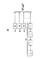
図1に示されるように、装置100は、音声/映像入出力(AVIO)ブロック101、フロント音声/映像(FAV)コネクタ102、デジタル処理ブロック103、フロントパネルアセンブリ(FPA)104、赤外線(IR)プリアンプ105、音声ブロック106、電源107、サブウーファアンプ/電源108、サブウーファ109、偏向ブロック110、収束ブロック111、CRT112〜114及びヨーク115〜117から構成される。図1の前記要素は、図1に示されるデータラインにより示されるように動作可能に接続される。当業者には直感的に明らかなように、図1に表される要素の多数、あるいはそれらの組み合わせは集積回路(IC)を用いて実現されてもよい。
As shown in FIG. 1, the
AVIOブロック101は、以下に限定されるものではないが、S−video入力、RF入力、コンポーネント入力及びIEEE1394入力を含む各種入力端子を備え、図1に示されるように、音声入力、映像入力、制御入力及び/または他の入力の受信と、装置100の他の要素への処理信号の出力を実行することができる。一実施例によると、AVIOブロック101は、以下に限定されるものではないが、図2に示される装置などの複数の外部ソースから、音声入力、映像入力及び/または制御入力を受け取る。
The
図1及び図2に示されるように、AVIOブロック101は、例示のため図2に示されるそれぞれDBS受信機、VCR及びDVDプレーヤーからなる外部装置201〜203から音声入力、映像入力及び/または他の入力を受け取る。従って、装置201〜203は、装置100に対する送信元装置である。他の外部装置がAVIOブロック101に接続されてもよく、例えば、そのような装置の数は、AVIOブロック101により提供される入力端子数に依存するかもしれない。
As shown in FIG. 1 and FIG. 2, the
AVIOブロック101は、IEEE1394バスネットワークなどの少なくとも1つの双方向デジタルデータバスネットワーク210(図2を参照せよ)に動作可能に接続される。図2に示されるように、データバスネットワーク210には、IEEE1394バスプロトコルによるなど既知の方法により、互いに通信可能なN個までの相互接続装置(例えば、テレビ信号受信機、パーソナルコンピュータ、表示装置、VCR、DVDプレーヤーDBS受信機及び/または他の装置)が含まれる。一実施例によると、Nは63に等しい。装置100は、AVIOブロック101を介してデータバスネットワーク210上の任意の装置と音声信号、映像信号、制御信号及び/または他の信号をやりとりするようにしてもよい。データバスネットワーク210は、以下に限定されるものではないが、図2に示される一例となる構成及び/または他の構成などの様々な異なる構成により構築されてもよい。
AVIO
AVIOブロック101はまた、音声ブロック106から処理された音声入力を受け取る。一実施例によると、AVIOブロック101は、偏向ブロック110へのコンポーネント映像信号(例えば、2H、2.14H、Y、Pr、Pb映像情報)を出力しながら、追加的処理のためデジタル処理ブロック103への入出力コンポジット映像信号及びすべての音声信号を処理する。FAVコネクタ102は、音声入力及び/または映像入力をAVIOブロック101に提供することができる。
AVIO
デジタル処理ブロック103は、チューニング、復調、信号解凍、メモリ及び他の機能などの装置100の各種デジタル機能を実行することができる。デジタル処理ブロック103は、処理された映像信号を視覚的表示を可能にする偏向ブロック110に出力する。後述されるように、デジタル処理ブロック103はまた、特にデータバスネットワーク210上で接続される装置に対する補助的アナログ接続のユーザによる指定を可能にする。
The
FPA104は、IR携帯型リモコン、キーパッドあるいは他の入力装置などのユーザ入力装置(UID)からユーザ入力を受け取り、このユーザ入力に対応する信号をIRプリアンプ105に出力するインタフェースである。IRプリアンプ105は、デジタル処理ブロック103への出力のため、FPA104から与えられた信号を増幅することができる。
The
音声ブロック106は、各種音声処理機能の実行及び処理された音声信号の出力を行うことができる。一実施例によると、音声ブロック106は、センタチャネル入力信号を受け取り、音声出力信号の生成のためこの入力信号を処理する。図1に示されるように、音声ブロック106は、音声出力信号を装置100の外部と内部両方のスピーカに提供することができる。さらに、音声ブロック106は、音声出力信号をAVIOブロック101に提供し、さらにサブウーファ音声信号をサブウーファアンプ/電源108に提供する。
The audio block 106 can execute various audio processing functions and output processed audio signals. According to one embodiment, the audio block 106 receives a center channel input signal and processes this input signal to generate an audio output signal. As shown in FIG. 1, the audio block 106 can provide audio output signals to both external and internal speakers of the
電源107は、図1に示されるように、入力された交流電流出力信号(AC−IN)を受け取り、装置100の各種要素を駆動する電圧信号を出力する。一実施例によると、電源107は、このような電圧信号をAVIOブロック101、デジタル処理ブロック103、音声ブロック106、サブウーファアンプ/電源108及び偏向ブロック110に提供する。サブウーファアンプ/電源108は、音声ブロック106から与えられるサブウーファ音声信号を増幅し、増幅されたサブウーファ音声信号をサブウーファ109に供給する。サブウーファアンプ/電源108はまた、電圧信号をサブウーファ109に出力し、それの電源として利用される。サブウーファ109は、サブウーファアンプ/電源108から与えられる増幅されたサブウーファ音声信号を聴覚的に出力することができる。
As shown in FIG. 1, the
偏向ブロック110は、装置100の偏向機能を制御することができる。一実施例によると、偏向ブロック110は、CRT112〜114により生成される高出力ビームの水平及び垂直方向の偏向をそれぞれ制御するヨーク115〜117に偏向制御信号を出力する。偏向ブロック110はまた、デジタル処理ブロック103から与えられる処理された映像信号と他の制御信号に応じたカラー制御信号をCRT112〜114に出力することができる。また、一実施例によると、偏向ブロック110は、電源の供給のため電圧信号を収束ブロック111とCRT112〜114に出力することができる。
The deflection block 110 can control the deflection function of the
収束ブロック111は、装置100の収束機能を制御する。一実施例によると、収束ブロック111は、CRT112〜114から照射される高出力ビームを画面(図示せず)上に正確にフォーカスする能動的収束調整を制御する、図1に示されるようなヨーク115〜117に収束制御信号を出力する。
The convergence block 111 controls the convergence function of the
CRT112〜114は、偏向ブロック110からのカラー制御信号に応じて、画面上への表示のためそれぞれ高出力の赤色ビーム、緑色ビーム及び青色ビームを生成する。ヨーク115〜117は、偏向ブロック110からの偏向制御信号と収束ブロック111からの収束制御信号に応じて、それぞれCRT112〜114を制御する。以下に限定されるものではないが、LCD、プラズマディスプレイ、OLED及びDLPディスプレイを含む他の適切な表示装置が利用されてもよい。
In response to the color control signal from the deflection block 110, the
図3に戻って、本発明の一特徴による一例となるステップを示すフローチャート300が示される。例示と説明のため、図3のステップは、図1の装置100と図2の一例となる外部装置を参照して説明される。図3のステップは単なる例示であり、本発明を限定するものではない。
Returning to FIG. 3, a
ステップ301において、装置100は、データバスネットワーク210上の装置を含む外部装置に接続される。一実施例よると、ユーザは、従来方法により図2の装置201〜203をAVIOブロック101の入力端子に物理的に接続し、これにより、音声及び/または映像入力信号を与えることにより、装置201〜203を装置100の送信元装置として機能させることを可能にする。またステップ301において、ユーザは、所望の構成により装置1〜Nを物理的に接続し、データバスネットワーク210上の装置の1つをAVIOブロック101の入出力端子(例えば、IEEE1394端子など)に接続することにより、図2のデータバスネットワーク210を構築する。一実施例よると、装置100は、送信先装置を表し、データバスネットワーク210上の装置1〜Nは送信元装置を表すかもしれない。前述のように、データバスネットワーク210は、以下に限定されるものではないが、図2に示される一例となる構成及び/または他の構成などの様々な異なる構成により構築されてもよい。
In
一実施例によると、装置100は、ステップ301において、補助的アナログ接続の必要性によりデータバスネットワーク210に接続されると、各装置を検出する。ネットワークへの新たな装置の認識及び追加、あるいはネットワークからの装置の削除におけるバスネットワークの動作は周知である。一般に、ネットワークに接続されると、当該ネットワークの設定の必要に応じて、装置の製造業者名、型名、GUIDやEUIDを含む識別子及び当該装置の各種出力と機能を含む識別データと制御データをネットワーク210上の各装置が提供する設定プロセスが実行される。そのようなデータは、一般に各装置の設定ROMに保持されている。そのようなデータはまた、当該装置が装置100への補助的アナログ接続を要するか示す。装置100あるいはネットワーク上の指定された装置は、このデータを(例えば、デジタル処理ブロック103のメモリに)保持し、データバスネットワーク210に対する装置の接続及び/または切断に応じてデータを更新する。このようにして、装置100は、任意の時点におけるデータバスネットワーク210上で装置100に接続されているすべての装置を、それらの補助的アナログ接続の必要性を含め追跡する。この時点において、ユーザは、周辺装置のアナログ出力を装置100の利用可能なアナログ入力の何れかに接続するようにしてもよい。
According to one embodiment,
ステップ301において装置100が外部装置に接続された後、処理フローはステップ302に移行し、補助的アナログ接続を要求するデータバスネットワーク210上のすべての装置に対するそのような接続のユーザによる指定を可能にする装置100の設定メニューにユーザはアクセスすることができる。一実施例によると、ユーザは、装置100により提供される各種画面上のメニューからユーザが選択できるUIDを介して装置100に入力を与えることにより、この設定メニューにアクセスするようにしてもよい。このようなメニューは、例えば、デジタル処理ブロック103のメモリに保持されてもよい。デジタル処理ブロック103は、CRT112〜114を介し表示される各種画面上のメニューの生成を可能にすることにより、ユーザ入力に応答する。
After the
ステップ303において、データバスネットワーク210上の何れの装置が装置100への補助的アナログ接続を必要としているか判断される。一実施例によると、デジタル処理ブロック103は、データバスネットワーク210に対する装置の追加及び/または削除に応じて以降に受け取られる任意のデータを含む、ステップ301においてデータバスネットワーク210上の装置から受信したデータに基づきこの判断を行う。
In
ステップ303における判断が否定的なものである場合、処理フローはステップ304に移行し、装置100が補助的アナログ接続を必要とするデータバスネットワーク210上のどの装置も検出していないということを示すため、画面表示が提供される。図4は、ステップ304における使用に適した一例となる画面表示400を示す。もちろん、画面表示400は単なる一例であり、文脈に依存したヘルプ情報などの他のアイテムが提供されてもよく、及び/または本発明による画面表示400において他のフォーマットが利用されてもよい。一実施例によると、ステップ304の画面表示は、デジタル処理ブロック103のメモリに保持され、デジタル処理ブロック103の制御の下、CRT112〜114を介し表示されてもよい。
If the determination in
あるいは、ステップ303における判断が肯定的なものである場合、処理フローはステップ305に移行し、装置100への補助的アナログ接続を要するデータバスネットワーク210上のすべての装置のリストを含む画面表示が提供される。図5は、そのようなリストを含む一例となる画面表示を示す。画面表示500はまた単なる一例であり、文脈に依存したヘルプ情報などの他のアイテムが提供されてもよく、及び/または本発明による画面表示500において他のフォーマットが利用されてもよい。一実施例によると、ステップ305の画面表示は、デジタル処理ブロック103のメモリに保持され、デジタル処理ブロック103の制御の下、CRT112〜114を介し表示されてもよい。ステップ305の画面表示はまた、送信元装置がデータバスネットワーク210に接続されているかを与えるものであってもよい。
Alternatively, if the determination in
本発明によると、ステップ305で表示される装置リストは、装置と関連するアナログ入力の選択を容易にするため、様々な方法により構成されてもよい。さらに、異なる送信先装置は、装置リストの提供方法に関して互いに異なるものであってもよい。図5の画面表示500において、例えば、表示される装置リストは、型名によりアルファベット順に配置されてもよい。型名は画面スペースを節約するため略名であってもよい。一例となる図5の画面表示500ではまた、表示される装置リストは、少なくとも2つの同一の装置、すなわち、同一の製造業者と型名を有する装置(すなわち、モデルLX600)を含む。本発明は、そのような同一の装置モデルの出現を自動認識し、数字による添え字及び/または他の表示などの型名に対する所定の表示子や表示を画面表示500上に添付することにより区別する。図5では、例えば、同一のモデルには数字による添え字(すなわち、LX600.1やLX600.2)が含まれる。同一のモデルのさらなる装置は同様にして識別することができる(例えば、LX600.3、LX600.4など)。このようにして、ユーザは、ステップ305において、表示リストにおける同一モデルの複数の装置を容易に区別することができる。
In accordance with the present invention, the device list displayed at
ステップ305において、表示リストにおける同一のモデルの識別に数字による添え字のような文字による指定が利用されるとき、文字指定の割当て方法のユーザにより指定を可能にすることが望ましい。例えば、どの装置が「1」の表示を有し、どの装置が「2」の表示を有するかなど、ユーザによる指定が許されてもよい。装置がネットワークに再追加されるときに識別子が自動的に維持されるように、添え字を含む表示をEUIDなどの装置に関連付けされた一意的な識別子に関連付けした表を保持することにより、表示子は恒久的に維持される。この柔軟性は、例えば、データバスネットワーク210に対して装置が頻繁に追加及び/または削除されるとき効果的であるかもしれない。あるいは他の構成では、文字表示の割当て方法をユーザが指定することは望ましくないかもしれない。そのような文字表示はまた装置100により自動的に割り当てられてもよい。上記すべての実施例が本発明の範囲内にある。
In
他の実施例によると、ステップ305で表示される装置リストは、製造業者名によりアルファベット順に構成され、そのような名前は画面スペースを節約するため略名が使用されてもよい。さらなる他の実施例によると、ステップ305において表示される装置リストは、これら装置に関連付けされたデジタル識別コードに基づき配置されてもよい。例えば、各IEEE1394装置は、一意的な64ビット識別コード(EUID)を有する。従って、ステップ305に表示される装置リストは、例えば、コードの実際の表示とは無関係に、そのような識別コードにより表される値に基づき配置されてもよい(例えば、最小値から最大値になど)。そのような識別コードに基づく装置リストの配置は、装置の表示及び調整順の一貫性を可能にするため有益でありうる。さらに、そのような識別コードに基づく装置リストの配置は、1以上の装置に製造業者名や装置名がない場合に有益であるかもしれない。
According to another embodiment, the device list displayed in
さらなる他の実施例によると、ステップ305において表示される装置リストは、限定されるものではないが、前述のものなど(すなわち、型名、製造業者名、デジタル識別コードなど)の装置特性の組み合わせに基づき配置されてもよい。例えば、ステップ305において表示される装置リストは、装置名に先行する製造業者名によりアルファベット順に配置されてもよい。他の例として、ステップ305において表示される装置リストは装置識別コードに基づき配置されてもよく、これら装置は、型名などの他の特徴により表示リストにおいて識別されてもよい。本発明により、他の組み合わせもまた利用可能である。さらに、ユーザには、各自の装置名を選択する選択肢が与えられてもよい。
According to yet another embodiment, the device list displayed in
ステップ306において、ステップ305でリストされたネットワーク装置に対する補助的アナログ接続がユーザにより指定されてもよい。一実施例によると、ステップ305において提供された画面表示リストに応じたUIDを介し入力を装置100に与えることにより、ユーザはこれら接続を指定する。指定された接続に対応するデータは、その後、デジタル制御ブロック103の制御の下、(例えば、ブロック103の)メモリに保持され、これにより、必要に応じてユーザにより指定された装置接続が装置100の動作中に利用されることが可能となる。例えば、図5では、ユーザは、モデルACT100に対しては入力1を、モデルAXT100に対しては入力2を、モデルLD500に対しては入力5を、第1モデルLX600に対しては入力6を、第2モデルLX600に対しては入力7を、モデルXSC254に対しては入力10を選択している。ステップ306においてユーザにより指定される接続数は、もちろん設計選択の問題である装置100上で利用可能な入力接続数の影響を受ける。
In
前述のように、本発明は、便利かつ時間効率的方法により、IEEE1394などのデータバスネットワーク上の装置に対するユーザによるアナログ接続の指定を可能にする方法及び装置を提供する。本発明は、上述の各種信号処理機能を実行する様々な電子装置に適用可能である。従って、ここで使用される「テレビ信号受信機」という用語は、以下に限定されるものではないが、テレビ装置、コンピュータ、モニタ、セットトップボックス、VCR、DVDプレーヤー、ステレオ、テレビゲーム機、パーソナルビデオレコーダ(PVR)及び/または他の装置を含む装置を呼ぶものである。さらに、実施例が説明されたが、前述の機能は、必要に応じてマイクロプロセッサ、メモリ要素、装置制御要素及びソフトウェア要素を含む各種要素あるいはそれらの組み合わせを利用して実現されてもよいということは当業者には明らかであろう。 As mentioned above, the present invention provides a method and apparatus that allows a user to specify an analog connection to a device on a data bus network such as IEEE 1394 in a convenient and time efficient manner. The present invention is applicable to various electronic devices that perform the various signal processing functions described above. Accordingly, the term “TV signal receiver” as used herein is not limited to the following, but includes a television device, a computer, a monitor, a set-top box, a VCR, a DVD player, a stereo, a video game machine, and a personal computer. Refers to a device that includes a video recorder (PVR) and / or other devices. Furthermore, although the embodiments have been described, the above-described functions may be realized by using various elements including a microprocessor, a memory element, a device control element, and a software element, or a combination thereof, as necessary. Will be apparent to those skilled in the art.
本発明は好適な設計を有するものとして説明されてきたが、本開示の趣旨及び範囲内での変更が可能である。従って本出願は、本発明の一般原理を利用した任意の変形、利用あるいは応用をカバーするものとされる。さらに本出願は、本発明の属する技術分野及び添付されたクレームの限定内における既知あるいは慣用的な実践の範囲内にあるような本開示からの逸脱をカバーするものとする。 While this invention has been described as having a preferred design, modifications can be made within the spirit and scope of this disclosure. Accordingly, this application is intended to cover any variations, uses, or applications that utilize the general principles of the present invention. Furthermore, this application is intended to cover any deviations from the present disclosure that are within the scope of known or routine practice within the technical field of the invention and the limitations of the appended claims.
Claims (3)
デジタルデータバスを介し前記映像装置と複数の周辺装置のデジタル接続とを物理的に接続するステップと、
前記デジタルデータバスを介し前記複数の周辺装置の各々からデータを受信するステップと、
前記受信したデータから、前記複数の周辺装置の何れかがさらにアナログ接続を有しているか判断するステップと、
前記複数の周辺装置の何れもアナログ接続を有しない場合、前記複数の周辺装置の何れもアナログ接続を有しないことを示す第1画面表示を提供するステップと、
前記複数の周辺装置の少なくとも1つがアナログ接続を有する場合、前記アナログ接続を有する少なくとも1つの周辺装置のリストを有する第2画面表示を提供するステップと、
前記リストからのユーザ選択に応答して、前記アナログ接続を有する少なくとも1つの周辺装置の選択された1つの周辺装置と前記映像装置の選択されたアナログ接続とを関連付けるステップと、
前記リストからのユーザ選択に応答して、関連付けデータを前記映像装置のメモリに格納するステップと、
から構成されることを特徴とする方法。A control method of a video device,
Physically connecting the video device and digital connections of a plurality of peripheral devices via a digital data bus;
Receiving data from each of the plurality of peripheral devices via the digital data bus;
Determining from the received data whether any of the plurality of peripheral devices further has an analog connection;
Providing a first screen display indicating that none of the plurality of peripheral devices has an analog connection if none of the plurality of peripheral devices have an analog connection;
Providing a second screen display having a list of at least one peripheral device having the analog connection if at least one of the plurality of peripheral devices has an analog connection ;
Associating a selected peripheral device of at least one peripheral device having the analog connection with the selected analog connection of the video device in response to a user selection from the list ;
In response to user selection from the list, storing association data in a memory of the video device;
A method comprising:
デジタルデータバスの設定モード中、前記デジタルデータバスを介し前記複数の周辺装置の各々から識別情報を受信するステップを備え、
前記第2画面表示は、前記識別情報を含むことを特徴とする方法。The control method according to claim 1, further comprising:
Receiving identification information from each of the plurality of peripheral devices via the digital data bus during a digital data bus setting mode;
Said second screen display, the method which comprises the identification information.
前記物理的に接続するステップは、少なくとも1つの同一周辺装置群と前記映像装置とを物理的に接続することを含み、
当該方法はさらに、前記デジタルデータバス上の前記同一周辺装置を区別するため、前記少なくとも1つの同一周辺装置群に係る識別情報に所定の表示を添付するステップを有することを特徴とする方法。A control method according to claim 2, comprising:
The physically connecting step includes physically connecting at least one same peripheral device group and the video device;
The method further comprises the step of attaching a predetermined display to identification information relating to the at least one group of identical peripheral devices to distinguish the same peripheral devices on the digital data bus .
Applications Claiming Priority (3)
| Application Number | Priority Date | Filing Date | Title |
|---|---|---|---|
| US37513602P | 2002-04-24 | 2002-04-24 | |
| US37520702P | 2002-04-24 | 2002-04-24 | |
| PCT/US2003/012571 WO2003092279A1 (en) | 2002-04-24 | 2003-04-22 | Method and apparatus for specifying connections for devices on a data bus network |
Publications (3)
| Publication Number | Publication Date |
|---|---|
| JP2005524298A JP2005524298A (en) | 2005-08-11 |
| JP2005524298A5 JP2005524298A5 (en) | 2006-06-15 |
| JP4335129B2 true JP4335129B2 (en) | 2009-09-30 |
Family
ID=29273019
Family Applications (1)
| Application Number | Title | Priority Date | Filing Date |
|---|---|---|---|
| JP2004500503A Expired - Fee Related JP4335129B2 (en) | 2002-04-24 | 2003-04-22 | Method and apparatus for specifying connection of devices on a data bus network |
Country Status (8)
| Country | Link |
|---|---|
| US (1) | US8001300B2 (en) |
| EP (1) | EP1497982B1 (en) |
| JP (1) | JP4335129B2 (en) |
| KR (1) | KR20040104606A (en) |
| CN (1) | CN100405838C (en) |
| AU (1) | AU2003241310A1 (en) |
| MX (1) | MXPA04010493A (en) |
| WO (1) | WO2003092279A1 (en) |
Families Citing this family (11)
| Publication number | Priority date | Publication date | Assignee | Title |
|---|---|---|---|---|
| KR100558198B1 (en) * | 2003-09-17 | 2006-03-10 | 삼성전자주식회사 | Display apparatus and control method thereof |
| KR100576943B1 (en) * | 2003-12-12 | 2006-05-10 | 한국전자통신연구원 | Apparatus and operation method for transmission and channel change of digital broadcast stream in the home network system |
| KR100598129B1 (en) * | 2004-03-08 | 2006-07-10 | 삼성전자주식회사 | Video recording/reproducing apparatus and method for communication among devices |
| KR100574463B1 (en) * | 2004-08-05 | 2006-04-27 | 삼성전자주식회사 | host device and controlling method thereof |
| KR100794770B1 (en) * | 2006-05-03 | 2008-01-15 | 엘지전자 주식회사 | Analog-digital selection control method for ieee1394 |
| JP4270270B2 (en) * | 2006-12-05 | 2009-05-27 | ソニー株式会社 | Electronic device, imaging apparatus, electronic device control method and program |
| US20100103321A1 (en) * | 2007-03-09 | 2010-04-29 | Pioneer Corporation | Av processing apparatus and program |
| US8817189B2 (en) * | 2011-09-29 | 2014-08-26 | Lsi Corporation | Digital television with improved input selection functionality |
| KR20160028713A (en) * | 2014-09-04 | 2016-03-14 | 삼성전자주식회사 | User device, display apparatus, system and method for controlling display apparatus |
| KR20180056285A (en) * | 2016-11-18 | 2018-05-28 | 유한회사 셋토퍼 | An auxiliary integrated device for connecting a plurality of terminal devices |
| US11277659B2 (en) * | 2017-09-19 | 2022-03-15 | ROVl GUIDES, INC. | Systems and methods for navigating internet appliances using a media guidance application |
Family Cites Families (12)
| Publication number | Priority date | Publication date | Assignee | Title |
|---|---|---|---|---|
| GB9512068D0 (en) * | 1995-06-14 | 1995-08-09 | Thomson Consumer Electronics | Bus and interface system for consumer digital equipment |
| US5841987A (en) * | 1994-08-19 | 1998-11-24 | Thomson Consumer Electronics, Inc. | Simple bus and interface system for consumer digital equipment |
| JP3334866B2 (en) * | 1998-07-21 | 2002-10-15 | 日本ビクター株式会社 | Information reproducing device, information recording / reproducing device, information selective output device, and electronic equipment system |
| EP0975161A3 (en) * | 1998-07-21 | 2001-12-05 | Victor Company Of Japan, Limited | Information reproducing apparatus, information recording/reproducing apparatus and information selectively outputting apparatus, and electronic apparatus system thereof |
| US7131135B1 (en) * | 1998-08-26 | 2006-10-31 | Thomson Licensing | Method for automatically determining the configuration of a multi-input video processing apparatus |
| JP2000197159A (en) * | 1998-12-28 | 2000-07-14 | Sanyo Electric Co Ltd | Audio video control system |
| JP2000307613A (en) * | 1999-04-16 | 2000-11-02 | Sony Corp | Device and method for information processing and medium |
| JP4193013B2 (en) * | 1999-09-28 | 2008-12-10 | ソニー株式会社 | Information output device and connection relation management method |
| JP4310674B2 (en) | 2000-01-11 | 2009-08-12 | ソニー株式会社 | Method for selecting device connected to electronic apparatus and electronic apparatus equipped with this selection method |
| JP2002044532A (en) * | 2000-07-25 | 2002-02-08 | Toshiba Corp | Signal output device and signal output method |
| US6961099B2 (en) * | 2001-10-16 | 2005-11-01 | Sony Corporation | Method and apparatus for automatically switching between analog and digital input signals |
| JP3862588B2 (en) * | 2002-04-11 | 2006-12-27 | キヤノン株式会社 | COMMUNICATION DEVICE AND ITS CONTROL METHOD |
-
2003
- 2003-04-22 JP JP2004500503A patent/JP4335129B2/en not_active Expired - Fee Related
- 2003-04-22 CN CNB038132834A patent/CN100405838C/en not_active Expired - Fee Related
- 2003-04-22 KR KR10-2004-7017063A patent/KR20040104606A/en not_active Application Discontinuation
- 2003-04-22 US US10/512,358 patent/US8001300B2/en not_active Expired - Fee Related
- 2003-04-22 MX MXPA04010493A patent/MXPA04010493A/en active IP Right Grant
- 2003-04-22 AU AU2003241310A patent/AU2003241310A1/en not_active Abandoned
- 2003-04-22 EP EP03731041A patent/EP1497982B1/en not_active Expired - Fee Related
- 2003-04-22 WO PCT/US2003/012571 patent/WO2003092279A1/en active Application Filing
Also Published As
| Publication number | Publication date |
|---|---|
| EP1497982B1 (en) | 2011-11-02 |
| EP1497982A1 (en) | 2005-01-19 |
| US8001300B2 (en) | 2011-08-16 |
| JP2005524298A (en) | 2005-08-11 |
| KR20040104606A (en) | 2004-12-10 |
| US20050174254A1 (en) | 2005-08-11 |
| AU2003241310A1 (en) | 2003-11-10 |
| CN1659869A (en) | 2005-08-24 |
| MXPA04010493A (en) | 2005-08-19 |
| CN100405838C (en) | 2008-07-23 |
| WO2003092279A1 (en) | 2003-11-06 |
Similar Documents
| Publication | Publication Date | Title |
|---|---|---|
| JP4335129B2 (en) | Method and apparatus for specifying connection of devices on a data bus network | |
| US8364868B2 (en) | Device control apparatus, device control method and program for initiating control of an operation of an external device | |
| US20080271074A1 (en) | Method for providing service information and apparatus thereof | |
| US20110167465A1 (en) | Device control apparatus, device control method and computer program | |
| WO2014010981A1 (en) | Method for controlling external input and broadcast receiving apparatus | |
| KR100989975B1 (en) | Method and apparatus for selecting devices on a data bus | |
| JP2007521701A (en) | Method and apparatus for setting video input information | |
| US7903101B2 (en) | Display device and method with optimal external input setting capability | |
| US5959686A (en) | Apparatus and method for controlling sub monitors in a video communication system | |
| US7305504B2 (en) | IEEE 1394-adopted host device and control method thereof | |
| JP2008067284A (en) | Video display apparatus | |
| US10116881B2 (en) | Image apparatus and method for receiving video signal in multiple video modes | |
| CN1890962B (en) | Method and apparatus for performing selectable channel search | |
| US6130659A (en) | Signal management apparatus for use in display monitor of a multimedia computer system and method using on screen display | |
| EP1621011B1 (en) | Method and apparatus for controlling an external device by remapping keys on a user input device | |
| US20090157917A1 (en) | Signal processing apparatus and control method thereof | |
| JPH1196053A (en) | Information processor, information processing method and recording medium | |
| JP2005017817A (en) | Video signal supply device, video display terminal device, and signal input terminal selecting method for the same | |
| JP2009065267A (en) | Electronic equipment | |
| JP4946720B2 (en) | Video processing apparatus and physical address setting method | |
| JP2013062869A (en) | Method of controlling separation type television receiver | |
| JP2012110056A (en) | Video transmission system and physical address setting method |
Legal Events
| Date | Code | Title | Description |
|---|---|---|---|
| A521 | Request for written amendment filed |
Free format text: JAPANESE INTERMEDIATE CODE: A523 Effective date: 20060421 |
|
| A621 | Written request for application examination |
Free format text: JAPANESE INTERMEDIATE CODE: A621 Effective date: 20060421 |
|
| A131 | Notification of reasons for refusal |
Free format text: JAPANESE INTERMEDIATE CODE: A131 Effective date: 20090127 |
|
| A521 | Request for written amendment filed |
Free format text: JAPANESE INTERMEDIATE CODE: A523 Effective date: 20090427 |
|
| TRDD | Decision of grant or rejection written | ||
| A01 | Written decision to grant a patent or to grant a registration (utility model) |
Free format text: JAPANESE INTERMEDIATE CODE: A01 Effective date: 20090526 |
|
| A01 | Written decision to grant a patent or to grant a registration (utility model) |
Free format text: JAPANESE INTERMEDIATE CODE: A01 |
|
| A61 | First payment of annual fees (during grant procedure) |
Free format text: JAPANESE INTERMEDIATE CODE: A61 Effective date: 20090624 |
|
| FPAY | Renewal fee payment (event date is renewal date of database) |
Free format text: PAYMENT UNTIL: 20120703 Year of fee payment: 3 |
|
| R150 | Certificate of patent or registration of utility model |
Ref document number: 4335129 Country of ref document: JP Free format text: JAPANESE INTERMEDIATE CODE: R150 Free format text: JAPANESE INTERMEDIATE CODE: R150 |
|
| FPAY | Renewal fee payment (event date is renewal date of database) |
Free format text: PAYMENT UNTIL: 20120703 Year of fee payment: 3 |
|
| FPAY | Renewal fee payment (event date is renewal date of database) |
Free format text: PAYMENT UNTIL: 20130703 Year of fee payment: 4 |
|
| R250 | Receipt of annual fees |
Free format text: JAPANESE INTERMEDIATE CODE: R250 |
|
| S111 | Request for change of ownership or part of ownership |
Free format text: JAPANESE INTERMEDIATE CODE: R313113 |
|
| S531 | Written request for registration of change of domicile |
Free format text: JAPANESE INTERMEDIATE CODE: R313531 |
|
| R371 | Transfer withdrawn |
Free format text: JAPANESE INTERMEDIATE CODE: R371 |
|
| R371 | Transfer withdrawn |
Free format text: JAPANESE INTERMEDIATE CODE: R371 |
|
| R250 | Receipt of annual fees |
Free format text: JAPANESE INTERMEDIATE CODE: R250 |
|
| S531 | Written request for registration of change of domicile |
Free format text: JAPANESE INTERMEDIATE CODE: R313531 |
|
| R350 | Written notification of registration of transfer |
Free format text: JAPANESE INTERMEDIATE CODE: R350 |
|
| S111 | Request for change of ownership or part of ownership |
Free format text: JAPANESE INTERMEDIATE CODE: R313113 |
|
| R350 | Written notification of registration of transfer |
Free format text: JAPANESE INTERMEDIATE CODE: R350 |
|
| LAPS | Cancellation because of no payment of annual fees |