JP4333146B2 - Piezoelectric actuators, watches and portable devices - Google Patents
Piezoelectric actuators, watches and portable devices Download PDFInfo
- Publication number
- JP4333146B2 JP4333146B2 JP2003015252A JP2003015252A JP4333146B2 JP 4333146 B2 JP4333146 B2 JP 4333146B2 JP 2003015252 A JP2003015252 A JP 2003015252A JP 2003015252 A JP2003015252 A JP 2003015252A JP 4333146 B2 JP4333146 B2 JP 4333146B2
- Authority
- JP
- Japan
- Prior art keywords
- diaphragm
- rotor
- vibration
- piezoelectric actuator
- piezoelectric
- Prior art date
- Legal status (The legal status is an assumption and is not a legal conclusion. Google has not performed a legal analysis and makes no representation as to the accuracy of the status listed.)
- Expired - Fee Related
Links
Images


Description
【0001】
【発明の属する技術分野】
本発明は、圧電アクチュエータ、時計および携帯機器に関する。
【0002】
【従来の技術】
圧電素子は、電気エネルギーから機械エネルギーへの変換効率や、応答性に優れていることから、近年、圧電素子の圧電効果を利用した各種の圧電アクチュエータが開発されている。この圧電アクチュエータは、圧電ブザー、プリンタのインクジェットヘッド、あるいは超音波モータなどの分野に応用されている。
【0003】
図38は、従来の圧電アクチュエータを用いた超音波モータを模式的に示す平面図である。同図に示すように、この種の超音波モータは、つっつき型と呼ばれるものであって、圧電素子に結合した振動片の先端に、ロータ面を少し傾斜させて接触させてある。このような構成の下、発振部からの交流電圧によって圧電素子が伸縮し、振動片が長さ方向に往復運動すると、ロータの円周方向に分力が発生してロータが回転するようになっている。
【0004】
また、2個の超音波振動子(圧電素子)を備え、各超音波振動子をそれ自身の電気的な共振周波数で振動させ、この振動により振動片を変位させる技術が知られている(特開平10−225151号公報)。
【0005】
【発明が解決しようとする課題】
しかしながら、圧電素子の変位は印加電圧にもよるが微小であり、数μm程度であるのが通常であり、上述した共振周波数で振動させる場合でも同様である。このため、なんらかの増幅機構によって変位を増幅してロータに伝達することが行われている。しかし、増幅機構を用いた場合、それ自身を動かすためにエネルギーが消費され、効率が低下するといった問題がある。また、増幅機構を介する場合、安定したロータへの駆動力の伝達が困難となることもある。
【0006】
また、腕時計のような小型の携帯機器は電池で駆動されるため、消費電力や駆動電圧を低く抑える必要がある。したがって、そのような携帯機器に圧電アクチュエータを組み込む場合には、特に、そのエネルギー効率が高く、駆動電圧が低いことが要求される。
【0007】
ところで、時計などにおいて、日や曜などを表示するカレンダー表示機構では、電磁式のステップモータの回転駆動力を運針用の輪列を介して日車などにも間欠的に伝達し、日車を送り駆動するのが一般的である。一方、腕時計は手首にベルトを巻き付けて携帯するものであるから、携帯に便利なように薄型化の要求が古くからある。薄型化を追求するには、カレンダー表示機構の厚さを薄くすることも必要となる。しかし、ステップモータはコイルやロータといった部品を面外方向に組み込んで構成されるので、その厚さを薄くするには限界がある。このため、ステップモータを用いた従来のカレンダー機構は、構造的に薄型化には向かないという問題があった。
【0008】
特に、カレンダー表示機構のある時計と、係る機構のない時計との間で運針の機械系(いわゆるムーブメント)を共通化するためには、カレンダー表示機構を文字板側に構成する必要があるが、電磁式のステップモータでは文字板側に構成できる程の薄型化が困難である。したがって、従来の時計は、表示機構の有無によって運針の機械系を別々に設計して製造する必要があり、その生産性を向上させる際の問題となっていた。
【0009】
本発明は、上記の事情を考慮してなされたものであり、圧電素子の振動を効率よく伝達するとともに、小型・薄型化に適しており、かつ駆動力を安定して伝達できる圧電アクチュエータ、これを用いた時計機器および携帯機器を提供することを目的とする。
【0010】
上記課題を解決するため、本発明に係る圧電アクチュエータは、支持体と、長手方向を有する板状の圧電素子と補強板とが積層され、長手方向の端部において幅方向の中心からずれた位置に突起部を備えた振動板と、前記圧電素子の同一表面上に配置された複数の電極と、前記振動板の属する平面内で前記振動板を前記長手方向に振動させる縦振動、および前記平面内で前記振動板を前記長手方向と直交する方向である前記振動体の幅方向に揺動させる屈曲振動とのいずれかを選択し、前記電極に電圧を供給するスイッチとを備え、前記振動板は前記支持体に取り付けられて前記突起部が駆動対象のロータに当接されており、前記スイッチの切り換えによって、前記縦振動が選択された場合と前記屈曲振動が選択された場合とで電圧が供給される電極の数を異ならせて前記振動体の前記縦振動と前記屈曲振動を切り換え、前記駆動対象のロータの駆動方向を正逆に切り換えることを特徴としている。
【0021】
また、本発明に係る時計は、上記圧電アクチュエータを有することを特徴としている。
この構成によれば、内蔵される圧電アクチュエータが薄型化に適した構造であるため、時計全体を薄型化が容易となる。また、内蔵される圧電アクチュエータの高効率であるため、時計全体の消費エネルギーを低減することができる。
【0022】
また、本発明に係る携帯機器は、上記圧電アクチュエータを有することを特徴としている。
この構成によれば、内蔵される圧電アクチュエータが薄型化に適しているため、機器全体の薄型化が容易となるとともに、高効率の圧電アクチュエータを搭載しているので電池寿命が長くなり、携帯機器として好適である。
【0023】
【発明の実施の形態】
以下、図面を参照して本発明の実施形態について説明する。
A.第1実施形態
A−1.腕時計のカレンダー表示機構
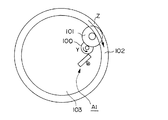
まず、図1は本発明の第1実施形態に係る圧電アクチュエータを備える腕時計のカレンダー表示機構を示す図である。同図に示すように、このカレンダー表示機構は、圧電アクチュエータA1、ロータ100、中間車101、および日や曜が表記されたリング状の日車102を備えている。
【0024】
地板(支持体)103に軸支されるロータ100は、圧電アクチュエータA1によって図中矢印Yで示す方向に回転駆動させられるようになっている。このロータ100には、地板103に軸支される中間車101が噛合されており、中間車101には日車102が噛合されている。この構成により、圧電アクチュエータA1に駆動されるロータ100の回転に伴って日車102が図中矢印Zで示す方向に回転させられるようになっている。
【0025】
次に、上述したカレンダー表示機構を組み込んだ時計の構成について図2を用いて説明する。同図において、斜線部分に上述したカレンダー表示機構が組み込まれている。カレンダー表示機構(斜線部分)の上側には、円盤状の文字板201が設けられている。この文字板201の外周部の一部には、日付を表示するために窓部202が設けられており、窓部202から日車102に表記された日付が覗けるようになっている。文字板201の下側には、運針203を駆動するムーブメント204が設けられている。この構成の下、日車102が回転させられることにより、上述した窓部202に表示される日や曜等の表示が切り換わるようになっている。
【0026】
A−2.圧電アクチュエータの構成
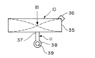
次に、図3および図4を参照して、本実施形態に係る圧電アクチュエータについて説明する。図3に示すように、圧電アクチュエータA1は、図の左右方向に長く形成された長板状の振動板10と、この振動板10を地板103(図1参照)に支持する支持部材11とを備えている。
【0027】
振動板10の長手方向の端部35には、突起部36がロータ100側に向けて突設されており、この突起部36がロータ100の側面に接触している。このような突起部36を設けることにより、ロータ100との接触面の状態等を維持するために突起部36に対してのみ研磨等の作業を行えばよいので、ロータ100との接触部の管理が容易となる。また、突起部36としては、導体または非導体のものを用いることができるが、非導体から形成するようにすれば、一般的に金属から形成されるロータ100と接触しても圧電素子30,31がショートしないようにすることができる。
【0028】
振動板10の長手方向の中央よりもややロータ100側には、支持部材11の一端部(取付部)37が取り付けられている。支持部材11の他端部(固定部)38は、ネジ39により地板103(図1参照)に支持されている。この構成の下、支持部材11は、その弾性力によって振動板10をロータ100側に付勢した状態で支持しており、これにより振動板10の突起部36はロータ100の側面に当接させられている。
【0029】
図4に示すように、振動板10は、2つの圧電素子30,31の間に、これらの圧電素子30,31よりも肉厚の小さいステンレス鋼などの補強板32を配置した積層構造となっている。このように圧電素子30,31の間に補強板32配置することにより、振動板10の過振幅や外力に起因する振動板10の損傷を低減することができる。また、補強板32としては、圧電素子30,31よりも肉厚の小さいものを用いることにより、圧電素子30,31の振動を極力妨げないようにしている。
【0030】
上下に配置された圧電素子30,31の面上には、それぞれ電極33が配置されている。この電極33を介して圧電素子30,31に、後述する導通構成から電圧が供給されるようになっている。ここで、圧電素子30,31としては、チタン酸ジルコニウム酸鉛(PZT(商標))、水晶、ニオブ酸リチウム、チタン酸バリウム、チタン酸鉛、メタニオブ酸鉛、ポリフッ化ビニリデン、亜鉛ニオブ酸鉛((Pb(Zn1/3-Nb2/3)03 1-x-Pb Ti 03 x)xは組成により異なる。x=0.09程度)、スカンジウムニオブ酸鉛((Pb((Sc1/2Nb1/2)1-x Tix)) 03)xは組成により異なる。x=0.09程度)等の各種のものを用いることができる。
【0031】
振動板10は、後述する駆動回路から電極33を介して圧電素子30,31に交流電圧が印加されると、圧電素子30,31が伸縮することによって振動するようになっている。その際、図5に示すように、振動板10が長手方向に伸縮する縦振動で振動するようになっており、これにより振動板10は図3中矢印で示す方向に振動することになる(無負荷状態、つまり突起部36がロータ100に接触していない状態)。また、上述したように振動板10を長板状の圧電素子30,31が積層された構造とし、並列接続して駆動することにより、低駆動電圧でより大きな変位を得ることができる。
【0032】
A−3.圧電アクチュエータの動作
次に、上記構成の圧電アクチュエータA1の動作について説明する。まず、図示せぬ駆動回路から振動板10に電圧が印加されると、圧電素子30,31の伸縮によって撓み振動し、図3に示すように、突起部36がロータ100と当接した状態で振動板10が矢印方向に振動する。この振動による突起部36に伴ってロータ100が図中矢印方向に回転させられる。このようにロータ100が回転させられることにより、中間車101を介して日車102が回転させられ(図1参照)、表示される日や曜が切り換わるようになっている。
【0033】
ここで、圧電アクチュエータA1では、ロータ100と当接させられる突起部36が図中一点鎖線で示す振動板10の中心線からずれた位置に設けられているため、ロータ100の側面からの反力によって振動板10には、図6に示すような屈曲振動が生じるようになっている。この屈曲振動と圧電素子30,31の伸縮によって生じる縦振動との振動周波数が略一致する、つまり共振するように印加電圧、振動板10の形状および突起部36の位置などを設定すれば、振動板10に生じる振動の振幅が大きくなる。このように圧電素子30,31の伸縮による縦振動と上述した屈曲振動とを共振させれば、図7に示すように、突起部36が楕円軌道に沿って移動するようになる。すなわち、縦振動と共振する屈曲振動を励振させれば、より大きな楕円軌道に沿って突起部36が移動することになる。このように大きな楕円軌道に沿って突起部36が移動するようにすれば、突起部36がロータ100と接触する時間が長くなり、接触時の突起部36の変位が大きくなる。従って、圧電素子30,31の伸縮による縦振動と共振するような屈曲振動を誘発させれば、より高効率の駆動力伝達を行うことができる。
【0034】
また、この圧電アクチュエータA1では、突起部36は支持部材11の弾性力によってロータ100側に付勢されているので、ロータ100と突起部36との間に十分な摩擦が得られるようになっている。これにより、突起部36とロータ100とがスリップすることが低減され、突起部36からロータ100への安定した駆動力伝達が可能となる。さらに、寸法誤差や経時変化などがあっても接触を保つことができる。なお、上述したロータ100からの反力による屈曲振動を誘発するためには、振動板10におけるロータ100との接触部、つまり突起部36が振動板10の中心線からずれていればよく、突起部36を図示の位置以外に設けるようにしてもよい。
【0035】
また、本実施形態に係る圧電アクチュエータA1では、図8中破線で示す振動板10の中心線の振幅の節となる位置、つまり振幅が極小となる位置に支持部材11の端部37が取り付けられている。具体的には、振動板10の長手方向の中央部よりもロータ100側に取り付けられている。これは、振動板10が上述したように長方形状の場合、無負荷時には振動板10の長手方向の中央部が振動の節になるが、上述したようにロータ100からの反力等の影響により、実際には図8に示したように、振動の節は中央部よりもロータ100側に位置することになるからである。このように振動板10を振動の節となる位置で支持することにより、振動エネルギーの損失が減少し、より高効率の駆動力伝達が可能となる。また、振動板10の振動に伴う支持部材11の振動の節の位置が支持部材11の端部37とほぼ一致するようにすれば、振動エネルギーの損失をさらに低減することができる。
【0036】
さらに、本実施形態に係る圧電アクチュエータA1では、圧電素子30,31と補強板32とが積層された構造の振動板10が増幅部材を介さずにロータ100を回転駆動することができるので、構成が簡易となり、装置の小型化が容易となる。また、圧電アクチュエータA1の機械的な構成要素は、振動板10と支持部材11だけであり、厚さ方向(図1の紙面垂直方向)に部品等を積層されていないため、薄型化も容易である。
【0037】
また、圧電アクチュエータA1では、ロータ100を図中矢印で示す方向にのみ駆動する構成であり、逆方向へロータ100を駆動するための別の振動板や、振動板のロータ100への当接方向を変化させる機構などがない、すなわち振動板10の振動を妨げる要素が少ないため、より効率よく駆動力を伝達することができる。
【0038】
また、本実施形態に係る圧電アクチュエータA1では、ロータ100を一方向にのみ駆動する構成であるため、ロータ100の逆方向への回転を規制する必要があるが、外力等によってロータ100が逆回転しようとすることがある。例えば、突起部36とロータ100との間の摩擦力を越える逆回転力が生じた場合、両者が滑ってしまい、ロータ100の逆回転を許容することになる。しかし、本実施形態に係る圧電アクチュエータA1では、図9に示すように、支持部材11が剛体ではなく弾性を有しているので、ロータ100が逆回転しようとした場合には、ロータ100の逆回転とともに、突起部36がロータ100と接触した状態で振動板10が回動することを許容するようになっている。そして、支持部材11の弾性力によって振動板10が図中一点鎖線で示す下の位置に戻る。このとき、突起部36とロータ100とが接触しているため、振動板10の戻りに合わせてロータ100も正方向に戻るようになる。従って、ロータ100の逆回転を規制することができる。ここで、図10に示すように、本実施形態では、振動板10の回動中心をロータ100と突起部36の接触点Aから点Aにおけるロータ100の駆動方向と逆方向に伸びる線Bと、点Aにおいて線Bと直交する線Cとによって形成される象限内に回動中心が位置するように設定されており、具体的には上述した象限内に属する支持部材11の端部38を中心として振動板10が回動することを許容するようになされている。このような位置に回動中心を設けることにより、上述したように振動板10によって回動および復帰動作が行われ、ロータ100の逆回転を抑制することができる。
【0039】
また、上述したように圧電アクチュエータA1をカレンダー表示機構に適用した場合には、圧電アクチュエータA1自体の小型化が容易であるため、カレンダー表示機構全体の寸法の大型化を招くことなく、ロータ100の径を大型にすることも可能となる。従って、圧電素子30,31に印加する電圧を大きくすることなく、圧電アクチュエータA1から得られるロータ100の回転トルクを大きくすることができる。
【0040】
A−4.圧電アクチュエータの変形例
なお、本発明に係る圧電アクチュエータは、上述した実施形態に限定されるものではなく、以下のような種々の変形も可能である。
【0041】
A−4−1.第1の変形例
上述した実施形態に示した圧電アクチュエータA1では、振動板10におけるロータ100との接触部に突起部36を設けるようにしていたが、図11に示すように、長方形状の振動板10のロータ100側の頂点を切り欠いた切り欠き部90を形成し、切り欠き部90をロータ100の側面と当接させるようにしてもよい。この場合にも、上述した突起部36と同様に切り欠き部90の表面状態の管理が容易となる。
【0042】
A−4−2.第2の変形例
また、上述した実施形態では、圧電素子30,31の全面上に電極33を設けるようにしていたが、図12に示すように、圧電素子30,31の中央部付近にのみ電極33を配置し、両端側には電極33を配置しないようにしてもよい。つまり、圧電素子30,31がその面上に電極を有する電極部と、その両端側に位置する無電極部を有する構成とするようにしてもよい。このようにすれば、ロータ100への駆動力を維持しつつ、低駆動電圧化が可能となる。これは、振動板10をその固有振動周波数で振動させた場合、その振動による振動板10の両端側の変位は十分大きく、その部分に電圧を印加して両端側の圧電素子30,31を伸縮させても、さらに変位を大きくするものとはならないためである。
【0043】
A−4−3.第3の変形例
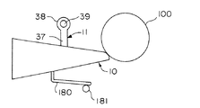
また、上述した実施形態では、長方形状の振動板10を用いるようにしていたが、図13に示すように、ロータ100側が細くなるテーパー状の振動板95を用いるようにしてもよい。このような形状の振動板95を作製する場合、上述した振動板10と同様にテーパー状の圧電素子と補強板を積層すればよい。このような振動板95を用いれば、振動板10のロータ100側の端部96の変位が大きくなり、駆動力の伝達効率が向上する。また、図の上下方向である幅方向の長さが不均一になるため、振動板10の幅方向の共振を抑制する、すなわち幅方向の振動を低減することができる。
【0044】
A−4−4.第4の変形例
また、図14に示すように、振動板10からロータ100側に延出するホーン部(延出部)110を設けるようにしてもよい。このようなホーン部110を設ける場合には、図15に示すように、補強板32を図示のようにホーン部110を含んだ形状に作製し、これの上下にそれぞれ圧電素子30,31を積層するようにすればよい。この構成の下、振動板10を振動させれば、図14中破線で示すような振幅で振動板10およびホーン部110が振動する。従って、ロータ100と当接するホーン部110の先端の変位が大きくなり、効率よく駆動力付与を行うことができる。なお、ホーン部110は図14に示すような形状に限らず、図16に示すような形状のものであってもよい。
【0045】
A−4−5.第5の変形例
また、図17に示すように、振動板10の突起部36とロータ100との接線、つまり振動初期状態での突起部36からロータ100への押し付け力Fの方向と垂直な線S、つまりロータ100と突起部36との当接点における駆動方向線上に支持部材11の端部38、つまり地板103に固定される部分がほぼ位置するようにしてもよい。このような位置関係となるように振動板10、支持部材11およびロータ100を配置すれば、突起部36のロータ100への押し付け力等を調整するために、ネジ39で固定された端部38を中心に支持部材11および振動板10の位置の微調整を行った場合にも、ロータ100と突起部36との接触位置や角度が変化せず、常に安定した駆動力付与を行うことができる。また、形状、位置ずれおよび経時変化などに起因する振動板とロータの接触角度の変化を防止することができる。
【0046】
A−4−6.第6の変形例
また、図18に示すように、2つの支持部材11で振動板10の長手方向の両端側をそれぞれ支持するようにしてもよい。このようにすれば、振動板10の幅方向(図の上下方向)の振動を抑制する、つまりロータ100の駆動に必要となる図の左右方向の振動の妨げとなる振動を抑制することができる。この場合、図19に示すように支持部材11における端部37が振動板10の振動に伴う支持部材11の振動の腹となる位置とほぼ一致する、例えば支持部材11の長さを支持部材11の振動波長の1/4となる長さにすれば、振動板10の図の左右方向の振動を妨げとなることが減少し、効率がさらに向上する。
【0047】
また、このように2つの支持部材11で振動板10を支持する場合、図20に示すように、いずれか一方の支持部材11で振動板10の振動の節となる位置を支持し、他方の支持部材11で振動板10におけるロータ100側の端部を支持するようにしてもよい。このようにすれば、一方の支持部材11は振動の節を支持するようにしているので、振動エネルギーの損失が減少するとともに、他方の支持部材11はロータ100との接触部付近での幅方向の振動を抑制することができる。
【0048】
A−4−7.第7の変形例
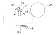
また、上述した実施形態では、支持部材11が振動板10をロータ100側に付勢するようにしていたが、図21に示すように、ばね部材(弾性部材)180を設けて振動板10をロータ100側に付勢するようにしてもよい。同図に示すように、振動板10の図の上側には支持部材11が取り付けられており振動板10の下側には、ばね部材180の一端が取り付けられている。ばね部材180の他端は、地板103(図1参照)に立設されたピン181に支持されている。これにより、振動板10は図の上側であるロータ100側に付勢され、突起部36がロータ100の側面に当接させられるようになっている。このようにばね部材180を設けて振動板10をロータ100側に付勢するようにすれば、上述した実施形態の圧電アクチュエータA1と同様に安定した駆動力の伝達を行うことができる。
【0049】
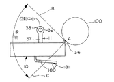
このように振動板10を支持する支持部材11と振動板10をロータ100側に付勢するばね部材180を設けた場合にも、図22に示すように、上述した実施形態と同様に線Bと線Cによって形成される象限内、例えば図示のように端部38の位置を中心として振動板10が回動できるようにしておけばよい。このようにすれば、外力によってロータ100が逆回転しようとした場合にも、図23に示すように、振動板10がロータ100の逆回転に伴って回動した後、振動板10が元の位置に戻ることにより、振動板10の戻りに伴ってロータ100が正方向に戻り、ロータ100の逆回転を抑制することができる。
【0050】
なお、このように支持部材11とばね部材180を設けた場合にも、図24に示すように、振動板10をテーパー状に形成してもよいし、またホーン部(図14参照)を設けるようにしてもよい。
【0051】
A−4−8.第8の変形例
また、上述した実施形態においては、振動板10が補強板32の上下に圧電素子30,31をそれぞれ積層した構造となっていたが、これに限らず、1つの圧電素子251の上下にそれぞれ補強板32を積層するようにしてもよい。この場合、図25に示すように、上層の補強板32を支持部材11aで支持し、下層の補強板32を支持部材11bで支持するようにし、補強板32および、支持部材11a,11bを導電体で形成すればよい。この構成の下、駆動回路250から支持部材11a,11bおよび補強板32を介して駆動電圧を圧電素子251に供給するようにしてもよい。このようにすれば、支持部材11a,11bが振動板10をロータ100側に付勢しながら支持する機能に加えて圧電素子251に駆動電圧を供給する導通機能を有することになる。従って、別に圧電素子251に駆動電圧を供給するための導通構成を設ける必要がなくなり、構成が簡易となる。また、振動板10の振動の妨げとなる導通部品等が不要となり、効率のよい駆動力伝達を行うことができる。
【0052】
A−4−9.第9の変形例
また、図26および図27に示すように、補強板32とその上下に圧電素子30,31をそれぞれ積層した振動板10を用いる場合にも、導電体から形成される支持部材11c,11dを介して駆動回路250から圧電素子30,31に駆動電圧を供給するようにしてもよい。
【0053】
支持部材11cは、振動板10側で2つに分岐する形状になされており、上側(図26の紙面手前側)に分岐した上端部260、および下側(図の紙面奥側)に分岐した下端部261を有している。上端部260は、圧電素子30の面上に形成された電極33にはんだや導電性接着剤等により取り付けられており、下端部261は、圧電素子31の面上に形成された電極33にはんだや導電性接着剤等により取り付けられている。一方、支持部材11dは、補強板32に取り付けられており、これにより駆動回路250から圧電素子30,31に駆動電圧が供給されるようになっている。この場合にも、上述したように支持部材11c,11dが振動板10を支持する機能を有するとともに、圧電素子30,31への導通機能を有することになり、構成が簡易となるとともに、効率のよい駆動力伝達を行える。
【0054】
A−5.圧電アクチュエータへの導通構成
次に、上述した様々な態様の圧電アクチュエータの圧電素子に駆動回路から駆動電圧を供給する導通構成について説明する。上述した第8および第9の変形例で説明したように、導電体から形成される支持部材を介して駆動回路から圧電素子に駆動電圧を供給するようにしてもよいが、図28に示すような導通構成で圧電素子に駆動電圧を供給するようにしてもよい。同図に示すように、この導通構成では、C字状の弾性導通部材280で振動板10の上下面(電極33)を挟持させ、補強板32から駆動回路250に配線を接続している。このような弾性導通部材280を用いれば、簡易な構成でありながら、駆動回路250から上下に積層された圧電素子30,31に駆動電圧を供給することができる。
【0055】
また、図29および図30に示すように、振動板10に導線290を巻き付けるようにし、巻き付けた導線290を介して駆動回路250から駆動電圧を圧電素子30,31に供給するようにしてもよい。このようにしても簡易な導通構成で圧電素子30,31に駆動電圧を供給することができる。なお、上述したように弾性導通部材280や導線290を介して電圧を供給する場合、振動板10の積層構造は、上下面に電極が配置される構造であってもよいし、上下面に導体かなる補強板が配置される構造のものであってもよい。また、圧電素子と補強板の積層構造である振動板以外にも、圧電素子に電圧を供給する場合にも、上述した弾性導通部材280や導線290を用いることができる。
【0056】
B.第2実施形態
次に、本発明の第2実施形態に係る圧電アクチュエータについて説明する。図31に示すように、第2実施形態に係る圧電アクチュエータは、第1実施形態に係る圧電アクチュエータA1の振動板10の代わりに振動板310を備えた構成となっている。
【0057】
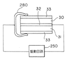
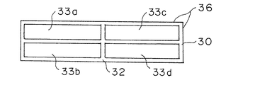
図32に示すように、振動板310は、第1実施形態における振動板10と同様に補強板32の上下に圧電素子30,31それぞれ積層した構造であるが、図33に示すように、圧電素子30,31上に電極33a,33b,33c,33dが配置されている点で振動板10と異なっている。同図に示すように、振動板310では、圧電素子30を(図示はしないが圧電素子31も同じ)4つの領域に分割し、分割された領域上にそれぞれ電極33a,33b,33c,33dを配置している。
【0058】
このように圧電素子30の4つの領域上に配置された電極33a,33b,33c,33dに駆動電圧を供給する導通構成について図34を用いて説明する。同図に示すように、スイッチ(選択手段)341のオン/オフを切り換えることによって、電源340から駆動電圧を全ての電極33a,33b,33c,33dに供給するモードと、電源340から電極33a,33dに供給するモードとを切り換えることができるようになっている。
【0059】
ここで、スイッチ341がオンになされ、全ての電極33a,33b,33c,33dに駆動電圧を供給するモードが選択された場合には、図35(a)に示すように、上述した第1実施形態と同様に振動板310が長手方向に伸縮して、振動板310の長手方向に縦振動するようになっている(以下、縦振動モードとする)。一方、スイッチ341がオフになされ、電極33a,33dにのみ駆動電圧を供給するモードが選択された場合には、駆動電圧が印加された領域のみの圧電素子が伸縮し、図35(b)に示すように、振動板310は振動板310の属する平面内で幅方向(図の上下方向)に屈曲振動するようになっている(以下、屈曲振動モードとする)。このように、スイッチ341を切り換えることによって振動板310の振動モードを選択することができるようになっている。
【0060】
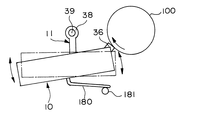
第2実施形態に係る圧電アクチュエータでは、上述したように2つの振動モードを切り換えることが可能な振動板310を用いてロータ100を駆動しており、振動モードを切り換えることによりロータ100の駆動方向を切り換えることができきるようになっている。縦振動モードが選択されている場合には、図36に示すように、振動板310の縦振動によって、ロータ100と突起部36の当接部から図中右向きの駆動力が付与され、これによりロータ100が図中反時計回りに回転させられる。
【0061】
一方、屈曲振動モードが選択された場合、図37に示すように、振動板310の屈曲振動によって、ロータ100と突起部36との当接部から図中上向きの駆動力が付与され、これによりロータ100が図中時計回りに回転させられるようになっている。
【0062】
第2実施形態に係る圧電アクチュエータでは、スイッチ341を切り換えることにより、ロータ100を正方向および逆方向に駆動することができる。上述したように振動板310の振動モードを切り換えることにより、駆動方向の切り換えを行うようにしたので、駆動方向毎に振動板を設けたり、振動板と駆動対象であるロータとの位置関係を調節する調節機構を設けたりする必要がない。従って、構成の複雑化および装置の大型化を招くことなく、駆動方向を正逆に切り換えることが可能である。
【0063】
なお、第2実施形態に係る圧電アクチュエータにおいても、上述した第1実施形態と同様に種々の変形が可能である。例えば、振動板310に突起部36の代わりに切り欠き部を設けるようにしてもよい(図11参照)。また、振動板310の突起部36とロータ100との接線上に支持部材11の端部38が位置するようにしてもよい(図17参照)。また、支持部材11に加えてばね部材を設けるようにし、このばね部材によって振動板310をロータ100側に付勢するようにしてもよい(図21参照)。
【0064】
C.変形例
なお、上述した様々な実施形態においては、圧電アクチュエータが円盤状のロータを回転駆動する構成となっていたが、駆動対象はこれに限定されるものではなく、例えば略直方体状の部材に上述した振動板を当接させ、この直方体状部材をその長手方向に駆動するようにしてもよい。
【0065】
また、上述した様々な実施形態に係る圧電アクチュエータは、時計のカレンダー表示機構に搭載される以外にも、電池駆動される時計以外の携帯機器に搭載して用いることも可能である。
【0066】
【発明の効果】
以上説明したように、本発明によれば、圧電アクチュエータにおける圧電素子の振動を効率よく伝達するとともに、小型・薄型化に適しており、かつ駆動力を安定して伝達できる。
【図面の簡単な説明】
【図1】 本発明の第1実施形態に係る圧電アクチュエータを備えた時計のカレンダー表示機構を示す平面図である。
【図2】 前記カレンダー表示機構を組み込んだ時計の概略構成を示す側断面図である。
【図3】 前記圧電アクチュエータの全体構成を示す平面図である。
【図4】 前記圧電アクチュエータの構成要素である振動板を示す側断面図である。
【図5】 前記振動板が縦振動する様子を示す図である。
【図6】 前記振動板が振動した場合に、前記カレンダー表示機構のロータからの反力によって屈曲振動する様子を示す図である。
【図7】 前記屈曲振動時における前記振動板に設けられた突起部の軌道を説明するための図である。
【図8】 前記振動板の振動時における振幅を説明するための図である0。
【図9】 前記ロータが逆回転しようとした場合の、前記振動板の状態を説明するための図である。
【図10】 前記振動板を回動自在に支持する回動中心の位置を説明するための図である。
【図11】 前記圧電アクチュエータの第1の変形例を示す平面図である。
【図12】 前記圧電アクチュエータの第2の変形例における振動板を示す側断面図である。
【図13】 前記圧電アクチュエータの第3の変形例を示す平面図である。
【図14】 前記圧電アクチュエータの第4の変形例を示す平面図である。
【図15】 前記圧電アクチュエータの第4の変形例の振動板の製造方法を説明するための図である。
【図16】 前記圧電アクチュエータの第4の変形例の他の変形例を示す図である。
【図17】 前記圧電アクチュエータの第5の変形例を示す平面図である。
【図18】 前記圧電アクチュエータの第6の変形例を示す平面図である。
【図19】 前記圧電アクチュエータの第6の変形例の構成要素である支持部材の振幅を説明するための図である。
【図20】 前記圧電アクチュエータの第6の変形例の他の例を示す平面図である。
【図21】 前記圧電アクチュエータの第7の変形例を示す平面図である。
【図22】 前記圧電アクチュエータの第7の変形例の構成要素である振動板を回動自在に支持する回動中心の位置を説明するための図である。
【図23】 前記第7の変形例において、前記ロータが逆回転しようとした場合の、前記振動板の振動板の状態を説明するための図である。
【図24】 前記圧電アクチュエータの第7の変形例の他の例を示す平面図である。
【図25】 前記圧電アクチュエータの第8の変形例を示す図である。
【図26】 前記圧電アクチュエータの第9の変形例を示す平面図である。
【図27】 前記圧電アクチュエータの第9の変形例を示す側面図である。
【図28】 前記圧電アクチュエータに駆動電圧を供給する導通構成を示す図である。
【図29】 前記圧電アクチュエータに駆動電圧を供給する導通構成の他の例を示す平面図である。
【図30】 前記圧電アクチュエータに駆動電圧を供給する導通構成の他の例を示す側面図である。
【図31】 本発明の第2実施形態に係る圧電アクチュエータ全体構成を示す平面図である。
【図32】 前記第2実施形態に係る圧電アクチュエータの構成要素である振動板を示す側面図である。
【図33】 前記第2実施形態に係る圧電アクチュエータの前記振動板を示す平面図である。
【図34】 前記第2実施形態に係る圧電アクチュエータに駆動電圧を供給する導通構成を示す図である。
【図35】 (a)は前記第2実施形態に係る圧電アクチュエータの前記振動板が縦振動する様子を示す図であり、(b)は前記振動板が屈曲振動する様子を示す図である。
【図36】 前記第2実施形態に係る圧電アクチュエータの前記振動板が縦振動した時の、前記ロータの駆動方向を説明するための図である。
【図37】 前記第2実施形態に係る圧電アクチュエータの前記振動板が屈曲振動した時の、前記ロータの駆動方向を説明するための図である。
【図38】 従来の圧電アクチュエータを用いた超音波式モータを模式的に示す平面図である。
【符号の説明】
10……振動板、11……支持部材、11a,11b,11c,11d……支持部材、30……圧電素子、31……圧電素子、32……補強板、33……電極、35……端部、36……突起部、37……端部(取付部)、38……端部(固定部)、90……切り欠き部、95……振動板、96……端部、100……ロータ、101……中間車、102……日車、103……地板(支持体)、110……ホーン部(延出部)、180……ばね部材(弾性部材)、250……駆動回路、251……圧電素子、280……弾性導通部材、290……導線、310……振動板、340……電源、341……スイッチ(選択手段)[0001]
BACKGROUND OF THE INVENTION
The present invention relates to a piezoelectric actuator, a timepiece, and a portable device.
[0002]
[Prior art]
Since piezoelectric elements are excellent in conversion efficiency from electrical energy to mechanical energy and responsiveness, various piezoelectric actuators utilizing the piezoelectric effect of piezoelectric elements have been developed in recent years. This piezoelectric actuator is applied to fields such as a piezoelectric buzzer, an inkjet head of a printer, or an ultrasonic motor.
[0003]
FIG. 38 is a plan view schematically showing an ultrasonic motor using a conventional piezoelectric actuator. As shown in the figure, this type of ultrasonic motor is called a puff type, and the rotor surface is brought into contact with the tip of a vibrating piece coupled to a piezoelectric element with a slight inclination. Under such a configuration, when the piezoelectric element expands and contracts due to the alternating voltage from the oscillating unit and the vibrating piece reciprocates in the length direction, a component force is generated in the circumferential direction of the rotor, and the rotor rotates. ing.
[0004]
There is also known a technique that includes two ultrasonic vibrators (piezoelectric elements), vibrates each ultrasonic vibrator at its own electrical resonance frequency, and displaces the resonator element by this vibration (special feature). (Kaihei 10-225151).
[0005]
[Problems to be solved by the invention]
However, the displacement of the piezoelectric element is minute although it depends on the applied voltage, and is usually about several μm, and the same applies to the case of vibrating at the resonance frequency described above. For this reason, the displacement is amplified by some amplification mechanism and transmitted to the rotor. However, when an amplification mechanism is used, there is a problem that energy is consumed to move itself and efficiency is lowered. In addition, when the amplification mechanism is used, it may be difficult to stably transmit the driving force to the rotor.
[0006]
In addition, since a small portable device such as a wristwatch is driven by a battery, it is necessary to reduce power consumption and driving voltage. Therefore, when a piezoelectric actuator is incorporated in such a portable device, it is particularly required that the energy efficiency is high and the driving voltage is low.
[0007]
By the way, in a calendar display mechanism that displays days, days of the week, etc. in a watch or the like, the rotational driving force of an electromagnetic step motor is intermittently transmitted to a date wheel or the like via a wheel train, and the date wheel is In general, it is feed-driven. On the other hand, wristwatches are carried around a wrist by wrapping a belt around them. Therefore, there has been a long-standing demand for thinning for convenience of carrying. In order to reduce the thickness, it is also necessary to reduce the thickness of the calendar display mechanism. However, since the step motor is constructed by incorporating components such as a coil and a rotor in the out-of-plane direction, there is a limit to reducing the thickness thereof. For this reason, the conventional calendar mechanism using a step motor has a problem that it is structurally unsuitable for thinning.
[0008]
In particular, in order to make the mechanical system of movement (so-called movement) between a watch with a calendar display mechanism and a watch without such a mechanism, it is necessary to configure the calendar display mechanism on the dial side, In an electromagnetic step motor, it is difficult to reduce the thickness so that it can be configured on the dial side. Accordingly, the conventional timepiece needs to be manufactured by separately designing the mechanical system of the hand movement depending on the presence or absence of the display mechanism, which has been a problem in improving the productivity.
[0009]
The present invention has been made in consideration of the above circumstances, and is a piezoelectric actuator that transmits vibrations of a piezoelectric element efficiently, is suitable for downsizing and thinning, and can stably transmit a driving force. It is an object to provide a clock device and a portable device using the.
[0010]
In order to solve the above problems, a piezoelectric actuator according to the present invention includes a support, a plate-shaped piezoelectric element having a longitudinal direction, and a reinforcing plate. , Provided with a protrusion at a position shifted from the center in the width direction at the end in the longitudinal direction A diaphragm, A plurality of electrodes disposed on the same surface of the piezoelectric element; Longitudinal vibration that causes the diaphragm to vibrate in the longitudinal direction within a plane to which the diaphragm belongs, and the diaphragm that is orthogonal to the longitudinal direction within the plane Direction of the vibrating body Select either flexural vibration that swings in the width direction Supply voltage to the electrode And the diaphragm is attached to the support. Please Above The protrusion is Drive target Rotor By switching the switch, When the longitudinal vibration is selected and the bending vibration is selected, the number of electrodes to which a voltage is supplied is changed to switch between the longitudinal vibration and the bending vibration of the vibrating body, Of the drive target Rotor of Drive Direction In reverse It is characterized by switching.
[0021]
A timepiece according to the present invention includes the piezoelectric actuator.
According to this configuration, since the built-in piezoelectric actuator has a structure suitable for thinning, the entire watch can be easily thinned. Further, since the built-in piezoelectric actuator is highly efficient, the energy consumption of the entire timepiece can be reduced.
[0022]
A portable device according to the present invention includes the piezoelectric actuator.
According to this configuration, since the built-in piezoelectric actuator is suitable for thinning, the entire device can be easily thinned, and the high-efficiency piezoelectric actuator is installed, so that the battery life is extended, and the portable device It is suitable as.
[0023]
DETAILED DESCRIPTION OF THE INVENTION
Hereinafter, embodiments of the present invention will be described with reference to the drawings.
A. First embodiment
A-1. Watch calendar display mechanism
First, FIG. 1 is a view showing a calendar display mechanism of a wristwatch provided with a piezoelectric actuator according to the first embodiment of the present invention. As shown in the figure, this calendar display mechanism includes a piezoelectric actuator A1, a
[0024]
The
[0025]
Next, a configuration of a timepiece incorporating the calendar display mechanism described above will be described with reference to FIG. In the figure, the calendar display mechanism described above is incorporated in the shaded portion. A disk-
[0026]
A-2. Configuration of piezoelectric actuator
Next, the piezoelectric actuator according to the present embodiment will be described with reference to FIGS. As shown in FIG. 3, the piezoelectric actuator A1 includes a long plate-
[0027]
A protruding
[0028]
One end portion (attachment portion) 37 of the
[0029]
As shown in FIG. 4, the
[0030]
[0031]
When an alternating voltage is applied to the
[0032]
A-3. Operation of piezoelectric actuator
Next, the operation of the piezoelectric actuator A1 having the above configuration will be described. First, when a voltage is applied to the
[0033]
Here, in the piezoelectric actuator A1, since the
[0034]
Further, in this piezoelectric actuator A1, since the
[0035]
Further, in the piezoelectric actuator A1 according to the present embodiment, the
[0036]
Further, in the piezoelectric actuator A1 according to the present embodiment, the
[0037]
In addition, the piezoelectric actuator A1 is configured to drive the
[0038]
In addition, since the piezoelectric actuator A1 according to the present embodiment is configured to drive the
[0039]
Further, when the piezoelectric actuator A1 is applied to the calendar display mechanism as described above, the piezoelectric actuator A1 itself can be easily reduced in size, so that the size of the entire calendar display mechanism is not increased. It is also possible to increase the diameter. Therefore, the rotational torque of the
[0040]
A-4. Modification of piezoelectric actuator
The piezoelectric actuator according to the present invention is not limited to the above-described embodiment, and various modifications as described below are possible.
[0041]
A-4-1. First modification
In the piezoelectric actuator A1 shown in the above-described embodiment, the
[0042]
A-4-2. Second modification
In the above-described embodiment, the
[0043]
A-4-3. Third modification
In the above-described embodiment, the
[0044]
A-4-4. Fourth modification
Further, as shown in FIG. 14, a horn part (extension part) 110 extending from the
[0045]
A-4-5. Fifth modification
Further, as shown in FIG. 17, a tangent line between the
[0046]
A-4-6. Sixth modification
In addition, as shown in FIG. 18, the two
[0047]
In addition, when the
[0048]
A-4-7. Seventh modification
In the above-described embodiment, the
[0049]
Even when the
[0050]
Even when the
[0051]
A-4-8. Eighth modification
In the above-described embodiment, the
[0052]
A-4-9. Ninth modification
Further, as shown in FIGS. 26 and 27, also when using the
[0053]
The support member 11c has a shape that branches into two on the
[0054]
A-5. Conduction configuration to piezoelectric actuator
Next, a conduction configuration for supplying a drive voltage from the drive circuit to the piezoelectric elements of the piezoelectric actuators of the various modes described above will be described. As described in the eighth and ninth modifications, the drive voltage may be supplied from the drive circuit to the piezoelectric element via the support member formed of a conductor, as shown in FIG. A driving voltage may be supplied to the piezoelectric element with a simple conduction configuration. As shown in the figure, in this conducting configuration, the upper and lower surfaces (electrodes 33) of the
[0055]
29 and 30, a
[0056]
B. Second embodiment
Next, a piezoelectric actuator according to a second embodiment of the present invention will be described. As shown in FIG. 31, the piezoelectric actuator according to the second embodiment has a configuration including a
[0057]
As shown in FIG. 32, the
[0058]
A conduction configuration for supplying a drive voltage to the
[0059]
Here, when the
[0060]
In the piezoelectric actuator according to the second embodiment, the
[0061]
On the other hand, when the bending vibration mode is selected, as shown in FIG. 37, the bending vibration of the
[0062]
In the piezoelectric actuator according to the second embodiment, the
[0063]
Note that the piezoelectric actuator according to the second embodiment can be variously modified similarly to the first embodiment described above. For example, the
[0064]
C. Modified example
In the various embodiments described above, the piezoelectric actuator is configured to rotationally drive the disk-shaped rotor. However, the driving target is not limited to this, and for example, the above-described member is a substantially rectangular parallelepiped member. You may make it contact | abut a diaphragm and drive this rectangular parallelepiped member to the longitudinal direction.
[0065]
The piezoelectric actuators according to the various embodiments described above can be mounted on a portable device other than a battery-driven timepiece, in addition to being mounted on a calendar display mechanism of a timepiece.
[0066]
【The invention's effect】
As described above, according to the present invention, the vibration of the piezoelectric element in the piezoelectric actuator can be efficiently transmitted, suitable for downsizing and thinning, and the driving force can be stably transmitted.
[Brief description of the drawings]
FIG. 1 is a plan view showing a calendar display mechanism of a timepiece provided with a piezoelectric actuator according to a first embodiment of the present invention.
FIG. 2 is a side sectional view showing a schematic configuration of a timepiece incorporating the calendar display mechanism.
FIG. 3 is a plan view showing an overall configuration of the piezoelectric actuator.
FIG. 4 is a side sectional view showing a diaphragm that is a component of the piezoelectric actuator.
FIG. 5 is a diagram illustrating a state in which the diaphragm vibrates longitudinally.
FIG. 6 is a diagram illustrating a state in which bending vibration is caused by a reaction force from a rotor of the calendar display mechanism when the vibration plate vibrates.
FIG. 7 is a diagram for explaining a trajectory of a protrusion provided on the diaphragm during the bending vibration.
FIG. 8 is a diagram for explaining an amplitude during vibration of the diaphragm;
FIG. 9 is a diagram for explaining a state of the diaphragm when the rotor is about to rotate backward.
FIG. 10 is a view for explaining a position of a rotation center that rotatably supports the diaphragm.
FIG. 11 is a plan view showing a first modification of the piezoelectric actuator.
FIG. 12 is a side sectional view showing a diaphragm in a second modification of the piezoelectric actuator.
FIG. 13 is a plan view showing a third modification of the piezoelectric actuator.
FIG. 14 is a plan view showing a fourth modification of the piezoelectric actuator.
FIG. 15 is a view for explaining a method of manufacturing a diaphragm according to a fourth modification of the piezoelectric actuator.
FIG. 16 is a diagram showing another modification of the fourth modification of the piezoelectric actuator.
FIG. 17 is a plan view showing a fifth modification of the piezoelectric actuator.
FIG. 18 is a plan view showing a sixth modification of the piezoelectric actuator.
FIG. 19 is a diagram for explaining the amplitude of a support member that is a component of a sixth modification of the piezoelectric actuator.
FIG. 20 is a plan view showing another example of the sixth modified example of the piezoelectric actuator.
FIG. 21 is a plan view showing a seventh modification of the piezoelectric actuator.
FIG. 22 is a view for explaining the position of a rotation center that rotatably supports a diaphragm that is a component of a seventh modification of the piezoelectric actuator.
FIG. 23 is a diagram for explaining a state of the diaphragm of the diaphragm when the rotor is about to rotate in the seventh modification.
FIG. 24 is a plan view showing another example of the seventh modified example of the piezoelectric actuator.
FIG. 25 is a diagram showing an eighth modification of the piezoelectric actuator.
FIG. 26 is a plan view showing a ninth modification of the piezoelectric actuator.
FIG. 27 is a side view showing a ninth modification of the piezoelectric actuator.
FIG. 28 is a diagram showing a conduction configuration for supplying a driving voltage to the piezoelectric actuator.
FIG. 29 is a plan view showing another example of a conduction configuration for supplying a driving voltage to the piezoelectric actuator.
FIG. 30 is a side view showing another example of a conduction configuration for supplying a driving voltage to the piezoelectric actuator.
FIG. 31 is a plan view showing an overall configuration of a piezoelectric actuator according to a second embodiment of the present invention.
FIG. 32 is a side view showing a diaphragm that is a component of the piezoelectric actuator according to the second embodiment.
FIG. 33 is a plan view showing the diaphragm of the piezoelectric actuator according to the second embodiment.
FIG. 34 is a diagram showing a conduction configuration for supplying a drive voltage to the piezoelectric actuator according to the second embodiment.
FIG. 35A is a diagram showing a state in which the diaphragm of the piezoelectric actuator according to the second embodiment vibrates longitudinally, and FIG. 35B is a diagram showing a state in which the diaphragm is flexibly vibrated.
FIG. 36 is a view for explaining the drive direction of the rotor when the diaphragm of the piezoelectric actuator according to the second embodiment vibrates longitudinally.
FIG. 37 is a view for explaining the driving direction of the rotor when the diaphragm of the piezoelectric actuator according to the second embodiment undergoes flexural vibration.
FIG. 38 is a plan view schematically showing an ultrasonic motor using a conventional piezoelectric actuator.
[Explanation of symbols]
DESCRIPTION OF
Claims (3)
長手方向を有する板状の圧電素子と補強板とが積層され、長手方向の端部において幅方向の中心からずれた位置に突起部を備えた振動板と、
前記圧電素子の同一表面上に配置された複数の電極と、
前記振動板の属する平面内で前記振動板を前記長手方向に振動させる縦振動、および前記平面内で前記振動板を前記長手方向と直交する方向である前記振動体の幅方向に揺動させる屈曲振動とのいずれかを選択し、前記電極に電圧を供給するスイッチとを備え、
前記振動板は前記支持体に取り付けられて前記突起部が駆動対象のロータに当接されており、
前記スイッチの切り換えによって、前記縦振動が選択された場合と前記屈曲振動が選択された場合とで電圧が供給される電極の数を異ならせて前記振動体の前記縦振動と前記屈曲振動を切り換え、前記駆動対象のロータの駆動方向を正逆に切り換える
ことを特徴とする圧電アクチュエータ。A support;
A plate-like piezoelectric element having a longitudinal direction and a reinforcing plate are laminated, and a diaphragm having a protrusion at a position shifted from the center in the width direction at an end in the longitudinal direction ;
A plurality of electrodes disposed on the same surface of the piezoelectric element;
Longitudinal vibration that causes the diaphragm to vibrate in the longitudinal direction within the plane to which the diaphragm belongs, and bending that causes the diaphragm to swing in the width direction of the vibrator that is perpendicular to the longitudinal direction within the plane. select one of the vibration, and a switch for supplying a voltage to the electrode,
The diaphragm is the protrusion mounting et al is in the support have been in contact with the rotor to be driven,
By switching the switch, the longitudinal vibration and the bending vibration of the vibrating body are switched by changing the number of electrodes to which a voltage is supplied when the longitudinal vibration is selected and when the bending vibration is selected. The piezoelectric actuator is characterized in that the driving direction of the rotor to be driven is switched between forward and reverse .
Priority Applications (1)
| Application Number | Priority Date | Filing Date | Title |
|---|---|---|---|
| JP2003015252A JP4333146B2 (en) | 1999-03-15 | 2003-01-23 | Piezoelectric actuators, watches and portable devices |
Applications Claiming Priority (3)
| Application Number | Priority Date | Filing Date | Title |
|---|---|---|---|
| JP6915899 | 1999-03-15 | ||
| JP11-69158 | 1999-03-15 | ||
| JP2003015252A JP4333146B2 (en) | 1999-03-15 | 2003-01-23 | Piezoelectric actuators, watches and portable devices |
Related Parent Applications (1)
| Application Number | Title | Priority Date | Filing Date |
|---|---|---|---|
| JP25022599A Division JP3719061B2 (en) | 1998-12-21 | 1999-09-03 | Piezoelectric actuators, watches and portable devices |
Publications (3)
| Publication Number | Publication Date |
|---|---|
| JP2003250284A JP2003250284A (en) | 2003-09-05 |
| JP2003250284A5 JP2003250284A5 (en) | 2006-10-19 |
| JP4333146B2 true JP4333146B2 (en) | 2009-09-16 |
Family
ID=28676578
Family Applications (1)
| Application Number | Title | Priority Date | Filing Date |
|---|---|---|---|
| JP2003015252A Expired - Fee Related JP4333146B2 (en) | 1999-03-15 | 2003-01-23 | Piezoelectric actuators, watches and portable devices |
Country Status (1)
| Country | Link |
|---|---|
| JP (1) | JP4333146B2 (en) |
Families Citing this family (1)
| Publication number | Priority date | Publication date | Assignee | Title |
|---|---|---|---|---|
| JP5466253B2 (en) * | 2006-01-17 | 2014-04-09 | セイコーインスツル株式会社 | Piezoelectric actuator and electronic device using the same |
-
2003
- 2003-01-23 JP JP2003015252A patent/JP4333146B2/en not_active Expired - Fee Related
Also Published As
| Publication number | Publication date |
|---|---|
| JP2003250284A (en) | 2003-09-05 |
Similar Documents
| Publication | Publication Date | Title |
|---|---|---|
| US7253552B2 (en) | Piezoelectric actuator, timepiece, and portable device | |
| JP3719061B2 (en) | Piezoelectric actuators, watches and portable devices | |
| JP3387101B2 (en) | Actuator, clock and alarm device using the same | |
| JP2005237102A (en) | Piezoelectric actuator, clock, and electronic equipment | |
| JP4222208B2 (en) | Piezoelectric actuator, timepiece including piezoelectric actuator, and portable device | |
| JP4333146B2 (en) | Piezoelectric actuators, watches and portable devices | |
| JP3632562B2 (en) | Piezoelectric actuators, watches and portable devices | |
| JP3614076B2 (en) | Piezoelectric actuator, watch, portable device, and driving method of piezoelectric actuator | |
| JP2002223577A (en) | Piezoelectric actuator, clock, mobile apparatus, and designing and manufacturing methods of the piezoelectric actuator | |
| JP2002223576A (en) | Piezoelectric actuator, clock, and mobile apparatus | |
| JP3832260B2 (en) | Piezoelectric actuators, watches and portable devices | |
| JP3649086B2 (en) | Piezoelectric actuators, watches and portable devices | |
| JP3614111B2 (en) | Piezoelectric actuator, timepiece, portable device, and adjustment method for adjusting pressing force in piezoelectric actuator | |
| JP4631124B2 (en) | Piezoelectric actuators, watches and equipment | |
| JP3680602B2 (en) | Piezoelectric actuators, watches and portable devices | |
| JP2001286167A (en) | Adjustment method of piezoelectric actuator and piezoelectric actuator | |
| JP3861563B2 (en) | Piezoelectric actuators, watches and portable devices | |
| JP3721928B2 (en) | Piezoelectric actuators, watches and portable devices | |
| JP2000188882A (en) | Drive device, calendar displaying device, portable apparatus, and timepiece | |
| JP2002233174A (en) | Piezoelectric actuator, manufacturing method for the actuator, wrist watch, and portable apparatus | |
| JP3832278B2 (en) | Piezoelectric actuators, watches and small equipment | |
| JP2000188885A (en) | Piezoelectric actuator, its manufacture, and timepiece | |
| JP2000188887A (en) | Piezoelectric actuator and timepiece | |
| JP2001268954A (en) | Actuator, rotor of actuator, method of manufacturing rotor, clock and portable device | |
| JP2004301626A (en) | Time measuring apparatus |
Legal Events
| Date | Code | Title | Description |
|---|---|---|---|
| A521 | Written amendment |
Free format text: JAPANESE INTERMEDIATE CODE: A523 Effective date: 20060904 |
|
| A621 | Written request for application examination |
Free format text: JAPANESE INTERMEDIATE CODE: A621 Effective date: 20060904 |
|
| A131 | Notification of reasons for refusal |
Free format text: JAPANESE INTERMEDIATE CODE: A131 Effective date: 20080916 |
|
| A521 | Written amendment |
Free format text: JAPANESE INTERMEDIATE CODE: A523 Effective date: 20081106 |
|
| TRDD | Decision of grant or rejection written | ||
| A01 | Written decision to grant a patent or to grant a registration (utility model) |
Free format text: JAPANESE INTERMEDIATE CODE: A01 Effective date: 20090602 |
|
| A01 | Written decision to grant a patent or to grant a registration (utility model) |
Free format text: JAPANESE INTERMEDIATE CODE: A01 |
|
| A61 | First payment of annual fees (during grant procedure) |
Free format text: JAPANESE INTERMEDIATE CODE: A61 Effective date: 20090615 |
|
| FPAY | Renewal fee payment (event date is renewal date of database) |
Free format text: PAYMENT UNTIL: 20120703 Year of fee payment: 3 |
|
| R150 | Certificate of patent or registration of utility model |
Free format text: JAPANESE INTERMEDIATE CODE: R150 |
|
| FPAY | Renewal fee payment (event date is renewal date of database) |
Free format text: PAYMENT UNTIL: 20120703 Year of fee payment: 3 |
|
| FPAY | Renewal fee payment (event date is renewal date of database) |
Free format text: PAYMENT UNTIL: 20130703 Year of fee payment: 4 |
|
| S531 | Written request for registration of change of domicile |
Free format text: JAPANESE INTERMEDIATE CODE: R313531 |
|
| R350 | Written notification of registration of transfer |
Free format text: JAPANESE INTERMEDIATE CODE: R350 |
|
| LAPS | Cancellation because of no payment of annual fees |