JP4331925B2 - Trigger type dispenser - Google Patents
Trigger type dispenser Download PDFInfo
- Publication number
- JP4331925B2 JP4331925B2 JP2002250021A JP2002250021A JP4331925B2 JP 4331925 B2 JP4331925 B2 JP 4331925B2 JP 2002250021 A JP2002250021 A JP 2002250021A JP 2002250021 A JP2002250021 A JP 2002250021A JP 4331925 B2 JP4331925 B2 JP 4331925B2
- Authority
- JP
- Japan
- Prior art keywords
- contents
- container
- cylinder
- nozzle
- piston
- Prior art date
- Legal status (The legal status is an assumption and is not a legal conclusion. Google has not performed a legal analysis and makes no representation as to the accuracy of the status listed.)
- Expired - Fee Related
Links
- 238000007599 discharging Methods 0.000 claims description 2
- 239000007788 liquid Substances 0.000 description 4
- 239000000203 mixture Substances 0.000 description 4
- 238000012856 packing Methods 0.000 description 2
- 239000000853 adhesive Substances 0.000 description 1
- 230000001070 adhesive effect Effects 0.000 description 1
- 239000000443 aerosol Substances 0.000 description 1
- 239000002537 cosmetic Substances 0.000 description 1
- 230000032798 delamination Effects 0.000 description 1
- 239000003814 drug Substances 0.000 description 1
- 229940079593 drug Drugs 0.000 description 1
- 238000001035 drying Methods 0.000 description 1
- 238000004043 dyeing Methods 0.000 description 1
- 230000000694 effects Effects 0.000 description 1
- 239000000463 material Substances 0.000 description 1
- 230000008023 solidification Effects 0.000 description 1
- 238000007711 solidification Methods 0.000 description 1
- 239000002699 waste material Substances 0.000 description 1
- XLYOFNOQVPJJNP-UHFFFAOYSA-N water Substances O XLYOFNOQVPJJNP-UHFFFAOYSA-N 0.000 description 1
Images


Landscapes
- Coating Apparatus (AREA)
- Containers And Packaging Bodies Having A Special Means To Remove Contents (AREA)
Description
【0001】
【発明の属する技術分野】
本発明は各容器内に充填された種類の異なる内容物をトリガの牽曳によってそれぞれ同時に吸引、加圧、混合して注出するトリガ式注出器に関するものである。
【0002】
【従来の技術】
接着剤等の日用品や毛染め液等の化粧料では、種類の異なる薬剤を、使用する直前に混合するタイプのものがあり、このような内容物の注出に当たっては、均一な混合と効率的な注出ができるようにポンプやエアゾール、あるいはトリガの牽曳によりピストンを駆動させてシリンダ内に内容物を吸引、加圧、混合して排出するガンタイプの注出器が使用されている。
【0003】
ところで、従来のガンタイプの注出器は、容器から内容物を注出する際にピストンの駆動にずれが生じることもあって均等に内容物を排出できない不具合がある。
【0004】
また、この種の注出器はトリガの一回当たりの牽曳によって注出される内容物の量は常に一定しており注出量の調整ができないことから内容物を無駄に排出してしまう場合もあり、使い勝手がよくないところに問題を残している。
【0005】
【発明が解決しようとする課題】
本発明の課題は、各容器から同等量の内容物を吸引、加圧して望ましい混合割合になる混合物を安定的に注出するとともに、内容物の注出量を適宜に調整できる新規なトリガ式注出器を提案するところにある。
【0006】
【課題を解決するための手段】
本発明は、トリガの牽曳にてシリンダ内のピストンを往復移動させて種類の異なる内容物を充填する各容器からそれぞれ同時に吸引、加圧、混合して注出する注出器であって、
容器内の内容物を吸引、加圧する少なくとも2本のシリンダと、これらのシリンダ内でそれぞれ同時に往復移動可能なピストンとを備え、
前記各シリンダに、内容物を充填した容器の口部にそれぞれつながる吸引通路を設け、この吸引通路を、各シリンダにて加圧された内容物をノズルに向けて排出する単一の排出通路を連結してなり、
ピストンの後端面に接触するとともに、それそのものの回転にてノズルに向けた移動、該ノズルから離れる向きへの移動を可能として該ピストンのシリンダ内における移動を規制して内容物の注出量を変更する注出量調整ロッドを設け、
前記各容器は、レフィル容器と、このレフィル容器を内装するとともに、その底部に凸部を設けた外筒からなる、ことを特徴とするトリガ式注出器である。
【0008】
【発明の実施の形態】
以下、図面を用いて本発明をより具体的に説明する。
【0009】
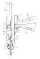
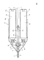
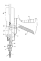
図1〜3は、本発明に従うトリガ式注出器を2液混合タイプの例で示したものであり、図において1a、1bは種類の異なる内容物を充填した容器(薄肉で減容可能なレフィル容器等)、2は容器1a、1bを装着、保持する注出器本体である。この注出器本体2はグリップ2aを有し容器1a、1bを装着、保持した状態で該容器1a、1bを覆い隠す揺動式のカバー2bを備えている。
【0010】
また、3a、3bは注出器本体2内に設けられた一対のシリンダであり、このシリンダ3a、3bは容器1a、1bのそれぞれの口部につながる吸引通路4a、4bとこの吸引通路4a、4bを通して導入された内容物を加圧して排出する単一の排出通路5を有している。
【0011】
また、6は吸引通路4a、4b及び排出通路5のそれぞれに配置された3点弁、7は排出経路5につながるノズル、8はノズル7の内側に配置され2種類の内容物を均一に混合するスクリュ型のミキサー、9a、9bはシリンダ3a、3b内にて摺動するピストン、10は注出器本体2に設けられた枢支ピン2cを支点にして牽曳可能に保持されその作用点pをピストン9a、9bの後端部のピン11a、11bに係合させたトリガ、そして12はピストン9a、9bの後端面に接触して該ピストン9a、9bのシリンダ内における移動量を調整して内容物の注出量を変更する注出量調整ロッドである。
【0012】
注出器本体2のグリップ2aを把持してトリガ10を複数回にわたり繰返し牽曳するとピストン9a、9bはシリンダ3a、3b内にてそれぞれ同時に往復移動し、これにより、容器1a、1b内の内容物は吸引通路4a、4bを経てシリンダ3a、3bに吸引されるとともに、吸引された内容物はシリンダ3a、3b内で加圧されて、排出通路5、ミキサー8を経てノズル7の先端から連続的に注出されることになる。
【0013】
上記の構成になる注出器においては、注出量調整ロッド12を回転させてノズル7に向けて移動させるとピストン9a、9bはシリンダ3a、3b内においてノズル7に向けて押圧されてトリガ10の牽曳の際のピストン9a、9bの移動量が小さくなる(注出量が小)。
【0014】
一方、注出量調整ロッド12を逆回転させるとピストン9a、9bはシリンダ2内においてノズル5から離れる向きに移動することとなり、これによってトリガ10を牽曳したときのピストン9a、9bの移動量が大きくなる(注出量が大)。
【0015】
上掲図1〜3では、容器1a、1bとしてレフィル容器1a 1 、1b 1 を適用する場合を例として示したが、図4〜6に示すように容器1a、1bは内層が外層の内壁面より剥離、減容するデラミ容器を用いることもできる。
【0016】
本発明ではその実施の形態として内容物を充填した容器を2本装着した2液混合タイプの注出器を例として示したが、シリンダとピストンの数を追加することで複数種類の内容物の混合、注出も可能であって2液混合する場合にのみ限定されない。また、容器は水平に並列配置してもよいし、縦に並列配置してもよくこの点に関しても限定されることはない。
【0017】
とくに上掲図1〜3に示したようなレフィル容器1a 1 、1b 1 を備えたものにおいては、該容器1a 1 、1b 1 を内装する外筒1a 2 、1b 2 が必要になるので、予め外筒1a 2 、1b 2 の底部に、凸部tを設けておき、レフィル容器1a 1 、1b 1 を吸引通路4a、4bから取り外し、外筒1a 2 、1b 2 内に水等を充填して外筒1a 2 、1b 2 を逆向きにセットしてトリガを牽曳することで、内容物が通る通路やノズル内を簡単に洗浄できる。
【0018】
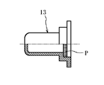
また、ミキサー8のみを洗浄するに際しては、ノズル5を取り外してノズル5の先端あるいは後端に向けて該ミキサー8を押し出すことで容易に分解することができるようにしておくのが望ましく、ノズル5を取り外した状態で注出器を収納しておくような場合には、図7に示すようなパッキンP付きのノズル用替えキャップ13を装着しておくことができ、これにより内容物の乾燥、固化を容易に防止することが可能になる。
【0019】
【発明の効果】
本発明によれば、トリガの牽曳に際して複数本のピストンを同時に駆動できるので内容物を容器から均等に排出することが可能であり、所定の混合割合になる混合物を安定して注出できる。
【0020】
また、本発明によれば、ピストンの動駆動機構はその本数にかかわりなく共有できるので部品点数の削減が可能であり注出器のコンパクト化が可能である。
【0021】
さらに本発明によれば、ロッドのねじ込み量を調整するだけで注出量を調整できるので内容物を無駄なく使用でき使い勝手が格段に改善される。
【図面の簡単な説明】
【図1】 本発明に従う注出器の側面を示した図である。
【図2】 図1の平面図である。
【図3】 図1の正面図である。
【図4】 注出器の他の例を示した図である。
【図5】 図4の平面図である。
【図6】 図4の正面図である。
【図7】 ノズル用替えキャップを示した図である。
【符号の説明】
1a 容器
1b 容器
2 注出器本体
2a グリップ
2b カバー
3a シリンダ
3b シリンダ
4a 吸引通路
4b 吸引通路
5 排出通路
6 3点弁
7 ノズル
8 ミキサー
9a ピストン
9b ピストン
10 トリガ
11a ピン
11b ピン
12 注出量調整手段
13 ノズル用替えキャップ
P パッキン[0001]
BACKGROUND OF THE INVENTION
The present invention relates to a trigger-type dispenser that dispenses different types of contents filled in each container by simultaneously sucking, pressurizing, and mixing them by trigger check.
[0002]
[Prior art]
Some types of cosmetics such as adhesives and hair dyeing liquids are mixed with different types of drugs immediately before use. Uniform mixing and efficiency are required when dispensing such contents. A gun-type dispenser that uses a pump, aerosol, or trigger to drive a piston to suck, pressurize, mix, and discharge the contents in the cylinder is used.
[0003]
By the way, the conventional gun-type dispenser has a problem that when the contents are poured out from the container, the drive of the piston may be displaced and the contents cannot be discharged evenly.
[0004]
In addition, this type of dispenser discharges the contents wastefully because the amount of the contents dispensed by the check per trigger is always constant and the amount of the dispenser cannot be adjusted. There are also problems that are not easy to use.
[0005]
[Problems to be solved by the invention]
An object of the present invention is to provide a novel trigger type capable of stably dispensing a mixture in which a desired mixing ratio is obtained by sucking and pressurizing the same amount of contents from each container and appropriately adjusting the amount of contents to be dispensed There is a place to propose an dispenser.
[0006]
[Means for Solving the Problems]
The present invention is a dispenser that performs suction, pressurization, mixing and dispensing from each container filled with different types of contents by reciprocating the piston in the cylinder with a trigger check,
Comprising at least two cylinders for sucking and pressurizing the contents in the container, and pistons capable of reciprocating simultaneously in these cylinders,
Each cylinder is provided with a suction passage connected to the mouth of the container filled with the contents, and this suction passage is provided with a single discharge passage for discharging the contents pressurized in each cylinder toward the nozzle. Concatenated,
While contacting the rear end surface of the piston, it can move toward the nozzle and move away from the nozzle by rotating itself, thereby restricting the movement of the piston in the cylinder and reducing the amount of content dispensed. A pouring amount adjustment rod to be changed is provided ,
Each said container is a trigger type | mold dispenser characterized by consisting of a refill container and the outer cylinder which equipped this refill container and provided the convex part in the bottom part .
[0008]
DETAILED DESCRIPTION OF THE INVENTION
Hereinafter, the present invention will be described more specifically with reference to the drawings.
[0009]
1 to 3 show a trigger type dispenser according to the present invention as an example of a two-liquid mixing type, in which 1a and 1b are containers filled with different kinds of contents (thin and can be reduced in volume). Refill container etc.) 2 is an extractor body for mounting and holding
[0010]
Further, 3a and 3b are a pair of cylinders provided in the
[0011]
Further, 6 is a three-point valve disposed in each of the
[0012]
When the
[0013]
In the dispenser configured as described above, when the dispensing
[0014]
On the other hand, when the dispensing
[0015]
In the upper掲図1-3, the container 1a, there is shown an example in which to apply the
[0016]
In the present invention, as an example, a two-liquid mixing type dispenser equipped with two containers filled with contents is shown as an embodiment, but by adding the number of cylinders and pistons, a plurality of kinds of contents can be added. Mixing and pouring are also possible and not limited to the case of mixing two liquids. Further, the containers may be arranged horizontally in parallel, or may be arranged vertically in parallel, and there is no limitation on this point.
[0017]
In particular, in those provided with the
[0018]
Further, when only the
[0019]
【The invention's effect】
According to the present invention, a plurality of pistons can be driven simultaneously when the trigger is checked, so that the contents can be evenly discharged from the container, and a mixture having a predetermined mixing ratio can be stably poured out.
[0020]
Further, according to the present invention, since the piston dynamic drive mechanism can be shared regardless of the number, the number of parts can be reduced and the dispenser can be made compact.
[0021]
Furthermore, according to the present invention, since the amount of pouring can be adjusted only by adjusting the screwing amount of the rod, the contents can be used without waste, and the usability is greatly improved.
[Brief description of the drawings]
FIG. 1 shows a side view of a dispenser according to the present invention.
FIG. 2 is a plan view of FIG.
FIG. 3 is a front view of FIG. 1;
FIG. 4 is a view showing another example of the dispenser.
FIG. 5 is a plan view of FIG. 4;
6 is a front view of FIG. 4;
FIG. 7 is a view showing a nozzle replacement cap.
[Explanation of symbols]
DESCRIPTION OF
Claims (1)
容器内の内容物を吸引、加圧する少なくとも2本のシリンダと、これらのシリンダ内でそれぞれ同時に往復移動可能なピストンとを備え、
前記各シリンダに、内容物を充填した容器の口部にそれぞれつながる吸引通路を設け、この吸引通路を、各シリンダにて加圧された内容物をノズルに向けて排出する単一の排出通路に連結してなり、
ピストンの後端面に接触するとともに、それそのものの回転にてノズルに向けた移動、該ノズルから離れる向きへの移動を可能として該ピストンのシリンダ内における移動量を規制して内容物の注出量を変更する注出量調整ロッドを設け、
前記各容器は、レフィル容器と、このレフィル容器を内装するとともに、その底部に凸部を設けた外筒からなる、ことを特徴とするトリガ式注出器。A dispenser that reciprocates the piston in the cylinder with the trigger check to simultaneously suck out different types of contents from each container and pressurize, mix, and pour out.
Comprising at least two cylinders for sucking and pressurizing the contents in the container, and pistons capable of reciprocating simultaneously in these cylinders,
Each cylinder is provided with a suction passage connected to the mouth of the container filled with the contents, and this suction passage serves as a single discharge passage for discharging the contents pressurized in each cylinder toward the nozzle. Concatenated,
The amount of content dispensed by restricting the amount of movement of the piston in the cylinder by contacting the rear end surface of the piston and allowing the piston to move toward the nozzle and move away from the nozzle. the dispensing amount adjusting rod to change the provided,
Each said container consists of a refill container and the outer cylinder which equipped this refill container and provided the convex part in the bottom part, The trigger type | mold extractor characterized by the above-mentioned.
Priority Applications (1)
| Application Number | Priority Date | Filing Date | Title |
|---|---|---|---|
| JP2002250021A JP4331925B2 (en) | 2002-08-29 | 2002-08-29 | Trigger type dispenser |
Applications Claiming Priority (1)
| Application Number | Priority Date | Filing Date | Title |
|---|---|---|---|
| JP2002250021A JP4331925B2 (en) | 2002-08-29 | 2002-08-29 | Trigger type dispenser |
Publications (2)
| Publication Number | Publication Date |
|---|---|
| JP2004082066A JP2004082066A (en) | 2004-03-18 |
| JP4331925B2 true JP4331925B2 (en) | 2009-09-16 |
Family
ID=32056954
Family Applications (1)
| Application Number | Title | Priority Date | Filing Date |
|---|---|---|---|
| JP2002250021A Expired - Fee Related JP4331925B2 (en) | 2002-08-29 | 2002-08-29 | Trigger type dispenser |
Country Status (1)
| Country | Link |
|---|---|
| JP (1) | JP4331925B2 (en) |
Families Citing this family (1)
| Publication number | Priority date | Publication date | Assignee | Title |
|---|---|---|---|---|
| JP7236360B2 (en) * | 2019-09-17 | 2023-03-09 | 株式会社Lixil | Structural sealant dispenser |
-
2002
- 2002-08-29 JP JP2002250021A patent/JP4331925B2/en not_active Expired - Fee Related
Also Published As
| Publication number | Publication date |
|---|---|
| JP2004082066A (en) | 2004-03-18 |
Similar Documents
| Publication | Publication Date | Title |
|---|---|---|
| US6454135B1 (en) | Dual liquid dispensing packages | |
| EP0388185B1 (en) | Multi-cavity dispensing container | |
| US5083683A (en) | Fingertip sprayer mounted on an angled neck container | |
| US20090263176A1 (en) | Replaceable Cartridge Dispenser Assembly | |
| KR102164743B1 (en) | A cosmetic container assembly which is able to discharge to contents at the same time | |
| WO2005011875A3 (en) | Spreader | |
| WO1997029850A1 (en) | Spray gun | |
| KR102157834B1 (en) | A cosmetic container assembly which is able to discharge to contents at the same time | |
| CN104296849A (en) | Handheld dosage-dispensing instrument for powderous or pasteous dosage material | |
| EP1281443A3 (en) | Pump dispenser and spraying apparatus provided with the same | |
| JP2007529375A (en) | Dispenser with sealed dispense valve unit | |
| KR102148690B1 (en) | A cosmetic container assembly which is able to discharge to contents at the same time | |
| DE50308202D1 (en) | Dispensers for liquid or pasty products | |
| US20050049558A1 (en) | Dispensing cartridge | |
| JP4331925B2 (en) | Trigger type dispenser | |
| JPH0712453B2 (en) | Dispensing device | |
| CA1334527C (en) | Dispenser with indicator | |
| CN114615911A (en) | Cosmetic container assembly capable of discharging a plurality of contents simultaneously | |
| CN114401902B (en) | Cosmetic container assembly capable of discharging multiple contents simultaneously | |
| JP4291554B2 (en) | Trigger type dispenser | |
| JP4607290B2 (en) | Container with pump | |
| JP4627006B2 (en) | Two-component mixing container with pump | |
| CN1747792A (en) | Pump | |
| WO2001041908A3 (en) | Dosing device for liquids | |
| KR100824307B1 (en) | Vacuum pumping vessel |
Legal Events
| Date | Code | Title | Description |
|---|---|---|---|
| A621 | Written request for application examination |
Free format text: JAPANESE INTERMEDIATE CODE: A621 Effective date: 20050331 |
|
| A977 | Report on retrieval |
Free format text: JAPANESE INTERMEDIATE CODE: A971007 Effective date: 20071011 |
|
| A131 | Notification of reasons for refusal |
Free format text: JAPANESE INTERMEDIATE CODE: A131 Effective date: 20071016 |
|
| RD03 | Notification of appointment of power of attorney |
Free format text: JAPANESE INTERMEDIATE CODE: A7423 Effective date: 20071206 |
|
| A131 | Notification of reasons for refusal |
Free format text: JAPANESE INTERMEDIATE CODE: A131 Effective date: 20080527 |
|
| A521 | Request for written amendment filed |
Free format text: JAPANESE INTERMEDIATE CODE: A523 Effective date: 20080711 |
|
| A131 | Notification of reasons for refusal |
Free format text: JAPANESE INTERMEDIATE CODE: A131 Effective date: 20080924 |
|
| A131 | Notification of reasons for refusal |
Free format text: JAPANESE INTERMEDIATE CODE: A131 Effective date: 20090113 |
|
| A521 | Request for written amendment filed |
Free format text: JAPANESE INTERMEDIATE CODE: A523 Effective date: 20090303 |
|
| A131 | Notification of reasons for refusal |
Free format text: JAPANESE INTERMEDIATE CODE: A131 Effective date: 20090331 |
|
| A521 | Request for written amendment filed |
Free format text: JAPANESE INTERMEDIATE CODE: A523 Effective date: 20090521 |
|
| TRDD | Decision of grant or rejection written | ||
| A01 | Written decision to grant a patent or to grant a registration (utility model) |
Free format text: JAPANESE INTERMEDIATE CODE: A01 Effective date: 20090616 |
|
| A01 | Written decision to grant a patent or to grant a registration (utility model) |
Free format text: JAPANESE INTERMEDIATE CODE: A01 |
|
| A61 | First payment of annual fees (during grant procedure) |
Free format text: JAPANESE INTERMEDIATE CODE: A61 Effective date: 20090619 |
|
| R150 | Certificate of patent or registration of utility model |
Free format text: JAPANESE INTERMEDIATE CODE: R150 |
|
| FPAY | Renewal fee payment (event date is renewal date of database) |
Free format text: PAYMENT UNTIL: 20120626 Year of fee payment: 3 |
|
| FPAY | Renewal fee payment (event date is renewal date of database) |
Free format text: PAYMENT UNTIL: 20120626 Year of fee payment: 3 |
|
| FPAY | Renewal fee payment (event date is renewal date of database) |
Free format text: PAYMENT UNTIL: 20130626 Year of fee payment: 4 |
|
| LAPS | Cancellation because of no payment of annual fees |