JP4331330B2 - Filling machine - Google Patents
Filling machine Download PDFInfo
- Publication number
- JP4331330B2 JP4331330B2 JP19319499A JP19319499A JP4331330B2 JP 4331330 B2 JP4331330 B2 JP 4331330B2 JP 19319499 A JP19319499 A JP 19319499A JP 19319499 A JP19319499 A JP 19319499A JP 4331330 B2 JP4331330 B2 JP 4331330B2
- Authority
- JP
- Japan
- Prior art keywords
- packaging material
- overlap portion
- filling machine
- overlap
- light
- Prior art date
- Legal status (The legal status is an assumption and is not a legal conclusion. Google has not performed a legal analysis and makes no representation as to the accuracy of the status listed.)
- Expired - Lifetime
Links
Images


Description
【0001】
【発明の属する技術分野】
本発明は、充填(てん)機に関するものである。
【0002】
【従来の技術】
従来、牛乳、清涼飲料水等の液体食品が充填された包装容器を製造する充填機においては、ウェブ状の包材を搬送しながら連続的にチューブ状にし、該チューブ状の包材内に液体食品を充填することによって包装容器を製造するようになっている。
【0003】
図2は従来の充填機の概念図、図3はオーバーラップ部の位置の蛇行を説明する図である。
【0004】
図において、11は包材であり、該包材11は、リール12の状態で包装機にセットされ、図示されない繰出機によって繰り出されて充填機内をウェブ状の形状で搬送される。
【0005】
続いて、ウェブ状の包材11は、図示されない案内用及び成形用のローラによって案内されながら徐々に湾曲させられ、チューブ状にされ、図示されない縦シール装置によって縦方向にシールされる。そして、チューブ状の包材11が下方に搬送される間に、充填用パイプ13を介して液体食品が上方から供給され、包材11内に充填される。次に、該包材11を両側から挟持し、所定の間隔ごとに横方向にシールすることによって、枕(まくら)状、袋状等の原型容器14が形成される。
【0006】
続いて、横方向に延びるシール部分S1を切断することによって原型容器14を分離させ、各原型容器14をあらかじめ形成された折り目に沿って所定の形状に成形することによって、包装容器15が完成される。
【0007】
ところが、ウェブ状の包材11を搬送する場合、包材11の両縁に対応させて形成された案内部材等によって包材11が蛇行するのを規制することができ、包材11の位置決めを比較的容易に行うことができるが、チューブ状の包材11を搬送する場合、包材11が湾曲させられているので、包材11の位置決めを行うことが困難である。
【0008】
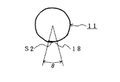
したがって、チューブ状の包材11が成形用のローラから力を受けて矢印A方向に回動し、それに伴って、縦方向に延びるシール部分、すなわち、オーバーラップ部S2が正しい位置からずれ、例えば、包材11の外側の端部18の位置に角度θの範囲でばらつきが生じることがある。そして、前記オーバーラップ部S2が正しい位置からずれたまま、原型容器14を所定の形状に成形して包装容器15を完成させると、包材11にあらかじめ設定された折り目の位置と実際の折り目の位置とが一致せず、包装容器15の外観が悪くなってしまう。
【0009】
そこで、包装容器15のサンプルを製造ラインから抜き取り、包材11にあらかじめ設定された折り目の位置と実際の折り目の位置とが一致しているかどうか、すなわち、成形が正しく行われているかどうかを目視で検査するようにしている。
【0010】
【発明が解決しようとする課題】
しかしながら、前記従来の充填機においては、検査を行うための作業が煩わしいだけでなく、すべての包装容器15について検査を行うことが困難である。
【0011】
そこで、包材11の画像を撮影し、得られた画像データに画像処理を施してオーバーラップ部S2を検出するようにした充填機が考えられる。ところが、画像処理を施すための画像処理装置が高価であるので、充填機のコストが高くなってしまうだけでなく、包装容器15の外装のデザインがノイズになるので、オーバーラップ部S2の検出精度がその分低くなってしまう。
【0012】
さらに、接触子を包材11に直接当てることによって前記オーバーラップ部S2を機械的に検出することが考えられるが、液体食品が飛散して接触子に付着することがあるので、オーバーラップ部S2の検出精度が低くなってしまう。
【0013】
本発明は、前記充填機の問題点を解決して、コストを低くすることができ、オーバーラップ部の検出精度を高くすることができる充填機を提供することを目的とする。
【0014】
【課題を解決するための手段】
そのために、本発明の充填機においては、オーバーラップ部を備えたチューブ状の包材を搬送する搬送手段と、前記包材の外周面のうち、オーバーラップ部を少なくとも含む部分に光を照射する光源と、該光源によって発生させられ、前記包材の外周面において反射された光を受けてセンサ出力を発生させる光検出手段と、前記センサ出力のピークによって前記オーバーラップ部を検出するオーバーラップ部検出手段とを有する。
【0015】
本発明の他の充填機においては、さらに、前記光源は、オーバーラップ部の端部の端面と対向させて配設される。
【0016】
本発明の更に他の充填機においては、さらに、前記光検出手段は、前記オーバーラップ部の端部より径方向外方に配設される。
【0017】
本発明の更に他の充填機においては、さらに、前記オーバーラップ部の位置を表示する表示装置を有する。
【0018】
本発明の更に他の充填機においては、さらに、前記オーバーラップ部の位置に基づいて駆動され、包材の位置を変更する駆動手段を有する。
【0019】
【発明の実施の形態】
以下、本発明の実施の形態について図面を参照しながら詳細に説明する。
【0020】
図1は本発明の第1の実施の形態における充填機の制御ブロック図、図4は本発明の第1の実施の形態におけるオーバーラップ部検出回路の制御ブロック図、図5は本発明の第1の実施の形態における包材の拡大図である。
【0021】
図において、11は縦方向にシールされ、オーバーラップ部S2を備え、図示されない搬送手段によって搬送されるチューブ状の包材であり、該包材11は、オーバーラップ部S2において両縁が重ねられ、外側の端部18によって外周面に段差が形成される。また、21は光源であり、該光源21は、前記包材11の外周面のうち、オーバーラップ部S2を少なくとも含む部分に光を照射する。そのために、光源21は、端部18における前記包材11の接線上において、端部18と所定の距離をおいて、かつ、端部18の端面と対向させて配設される。そして、22は、包材11の中心と端部18とを結ぶ線上において、前記端部18より径方向外方の所定の位置に配設された集光部材としてのレンズであり、該レンズ22は、前記光源21によって発生させられ、包材11の外周面において反射された光を集める。23は、包材11の中心と端部18とを結ぶ線上において、端部18及びレンズ22より径方向外方に、かつ、該レンズ22の光軸上に配設され、レンズ22によって集められた光を受けて、図4に示されるようなセンサ出力を発生させる光検出手段としてのCCDである。該CCD23は一次元のラインセンサであっても、二次元の面状センサであってもよい。前記レンズ22及びCCD23によって撮像手段が構成される。なお、24はオーバーラップ部検出回路である。
【0022】
前記CCD23はCCD駆動回路26によって駆動され、CCD23のセンサ出力はCCD駆動回路26を介して2値化部27に送られ、該2値化部27において2値化される。なお、本実施の形態においては、2値化部27としてコンパレータを使用することができ、該コンパレータは、あらかじめ設定された基準値と前記センサ出力とを比較し、1又は0の出力を発生させる。また、前記2値化部27の出力はオーバーラップ部検出手段28に送られ、該オーバーラップ部検出手段28によってオーバーラップ部S2が検出される。そして、該オーバーラップ部S2が検出されると、オーバーラップ部検出手段28の検出信号がディスプレイ等の表示装置31に送られ、該表示装置31によってオーバーラップ部S2の位置が表示される。
【0023】
ところで、前述されたように、チューブ状の包材11の側方から光を照射すると、包材11の外周面において反射された光のうち、端部18において反射された光の強度が大きく、図4に示されるように、CCD23のセンサ出力にピークが形成される。したがって、センサ出力にピークが形成される点をオーバーラップ部S2として検出することができる。この場合、端部18において反射された光は、前記包材11の他の部分において反射された光より強度が大きいので、包装容器15(図2参照)の外装のデザインがノイズになることはない。したがって、オーバーラップ部S2の検出精度を高くすることができる。
【0024】
また、原型容器14を所定の形状に成形して包装容器15を完成させたときに、成形が正しく行われているかどうかをオーバーラップ部S2の位置に基づいて判断することができる。したがって、包装容器15のサンプルを製造ラインから抜き取る必要がなくなるので、成形が正しく行われているかどうかの判断を行うための作業を簡素化することができ、包装容器15のコストを低くすることができる。また、すべての包装容器15について、成形が正しく行われているかどうかを判断することができる。
【0025】
そして、オーバーラップ部S2を検出するために、CCD23のセンサ出力を2値化させるだけでよく、撮影によって得られた画像データに画像処理を施す必要がないので、充填機のコストを低くすることができる。さらに、接触子を包材11に直接当てる必要がないので、オーバーラップ部S2の検出精度を高くすることができる。
【0026】
次に、本発明の第2の実施の形態について説明する。なお、第1の実施の形態と同じ構造を有するものについては、同じ符号を付与することによってその説明を省略する。
【0027】
図5は本発明の第2の実施の形態における充填機の制御ブロック図である。
【0028】
この場合、オーバーラップ部検出手段28によって発生させられた検出信号は、リアルタイムでドライバ32に送られる。そして、該ドライバ32は、図示されない制御装置によって設定されたオーバーラップ部S2の正しい位置と、前記オーバーラップ部検出手段28によって検出されたオーバーラップ部S2の位置とを比較し、偏差に基づいてフィードバック制御を行い、駆動手段としてのモータ33を駆動し、図示されない案内用及び成形用のローラの位置を調整する。その結果、の位置が変更され、オーバーラップ部S2が正しい位置に置かれる。この場合、包材11が無駄に消費されることがなくなる。
【0029】
なお、本発明は前記実施の形態に限定されるものではなく、本発明の趣旨に基づいて種々変形させることが可能であり、それらを本発明の範囲から排除するものではない。
【0030】
【発明の効果】
以上詳細に説明したように、本発明によれば、充填機においては、オーバーラップ部を備えたチューブ状の包材を搬送する搬送手段と、前記包材の外周面のうち、オーバーラップ部を少なくとも含む部分に光を照射する光源と、該光源によって発生させられ、前記包材の外周面において反射された光を受けてセンサ出力を発生させる光検出手段と、前記センサ出力のピークによって前記オーバーラップ部を検出するオーバーラップ部検出手段とを有する。
【0031】
この場合、包材の外周面において反射された光のうち、包材の端部において反射された光の強度が大きく、光検出手段のセンサ出力にピークが形成される。したがって、センサ出力にピークが形成される点をオーバーラップ部として検出することができる。
【0032】
また、前記端部において反射された光は、前記包材の他の部分において反射された光より強度が大きいので、包装容器の外装のデザインがノイズになることはない。したがって、オーバーラップ部の検出精度を高くすることができる。
【0033】
そして、原型容器を所定の形状に成形して包装容器を完成させたときに、成形が正しく行われているかどうかをオーバーラップ部の位置に基づいて判断することができる。したがって、包装容器のサンプルを製造ラインから抜き取る必要がなくなるので、成形が正しく行われているかどうかの判断を行うための作業を簡素化することができ、包装容器のコストを低くすることができる。また、すべての包装容器について、成形が正しく行われているかどうかを判断することができる。
【0034】
そして、光検出手段のセンサ出力を2値化させるだけでよく、撮影によって得られた画像データに画像処理を施す必要がないので、充填機のコストを低くすることができる。さらに、接触子を包材に直接当てる必要がないので、オーバーラップ部の検出精度を高くすることができる。
【図面の簡単な説明】
【図1】本発明の第1の実施の形態における充填機の制御ブロック図である。
【図2】従来の充填機の概念図である。
【図3】オーバーラップ部の位置の蛇行を説明する図である。
【図4】本発明の第1の実施の形態におけるオーバーラップ部検出回路の制御ブロック図である。
【図5】本発明の第1の実施の形態における包材の拡大図である。
【図6】本発明の第2の実施の形態における充填機の制御ブロック図である。
【符号の説明】
11 包材
18 端部
21 光源
23 CCD
28 オーバーラップ部検出手段
31 表示装置
33 モータ
S2 オーバーラップ部[0001]
BACKGROUND OF THE INVENTION
The present invention relates to a filling machine.
[0002]
[Prior art]
Conventionally, in a filling machine for manufacturing a packaging container filled with liquid food such as milk or soft drink, a web-like packaging material is continuously formed into a tube shape while liquid is contained in the tube-like packaging material. Packaging containers are manufactured by filling food.
[0003]
FIG. 2 is a conceptual diagram of a conventional filling machine, and FIG. 3 is a diagram for explaining meandering of the position of an overlap portion.
[0004]
In the figure,
[0005]
Subsequently, the web-
[0006]
Subsequently, the
[0007]
However, when the web-
[0008]
Therefore, the
[0009]
Therefore, a sample of the
[0010]
[Problems to be solved by the invention]
However, in the conventional filling machine, not only the operation for performing the inspection is troublesome, but also it is difficult to inspect all the
[0011]
Accordingly, a filling machine that takes an image of the
[0012]
Further, it is conceivable that the overlap portion S2 is mechanically detected by directly contacting the contact with the
[0013]
An object of the present invention is to provide a filling machine that can solve the problems of the filling machine, reduce the cost, and increase the detection accuracy of the overlap portion.
[0014]
[Means for Solving the Problems]
For this purpose, in the filling machine of the present invention, light is irradiated to a part including at least the overlap part of the transporting means for transporting the tubular packaging material provided with the overlap part and the outer peripheral surface of the packaging material. A light source, light detection means for generating a sensor output by receiving the light generated by the light source and reflected on the outer peripheral surface of the packaging material, and an overlap portion for detecting the overlap portion by the peak of the sensor output Detecting means.
[0015]
In another filling machine of the present invention, the light source is further arranged to face the end surface of the end portion of the overlap portion.
[0016]
In still another filling machine of the present invention, the light detection means is further arranged radially outward from the end of the overlap portion.
[0017]
Still another filling machine of the present invention further includes a display device for displaying the position of the overlap portion.
[0018]
Still another filling machine according to the present invention further includes a driving unit that is driven based on the position of the overlap portion to change the position of the packaging material.
[0019]
DETAILED DESCRIPTION OF THE INVENTION
Hereinafter, embodiments of the present invention will be described in detail with reference to the drawings.
[0020]
FIG. 1 is a control block diagram of a filling machine according to the first embodiment of the present invention, FIG. 4 is a control block diagram of an overlap portion detection circuit according to the first embodiment of the present invention, and FIG. It is an enlarged view of the packaging material in 1 embodiment.
[0021]
In the figure, 11 is a tube-shaped packaging material that is sealed in the vertical direction and has an overlap portion S2, and is conveyed by a conveying means (not shown). The
[0022]
The
[0023]
By the way, as described above, when light is irradiated from the side of the
[0024]
Further, when the
[0025]
Then, in order to detect the overlap portion S2, it is only necessary to binarize the sensor output of the
[0026]
Next, a second embodiment of the present invention will be described. In addition, about the thing which has the same structure as 1st Embodiment, the description is abbreviate | omitted by providing the same code | symbol.
[0027]
FIG. 5 is a control block diagram of the filling machine according to the second embodiment of the present invention.
[0028]
In this case, the detection signal generated by the overlap portion detection means 28 is sent to the
[0029]
In addition, this invention is not limited to the said embodiment, It can change variously based on the meaning of this invention, and does not exclude them from the scope of the present invention.
[0030]
【The invention's effect】
As described above in detail, according to the present invention, in the filling machine, the overlap portion of the transporting means for transporting the tubular packaging material provided with the overlap portion and the outer peripheral surface of the packaging material is provided. A light source for irradiating at least a portion including light, a light detection means for generating a sensor output upon receiving light reflected by the outer peripheral surface of the packaging material, and a peak of the sensor output. And an overlap part detecting means for detecting the wrap part.
[0031]
In this case, of the light reflected on the outer peripheral surface of the packaging material, the intensity of the light reflected at the end of the packaging material is large, and a peak is formed in the sensor output of the light detection means. Therefore, a point where a peak is formed in the sensor output can be detected as an overlap portion.
[0032]
In addition, since the light reflected at the end portion has a higher intensity than the light reflected at the other part of the packaging material, the packaging design of the packaging container does not become noise. Therefore, the detection accuracy of the overlap portion can be increased.
[0033]
Then, when the original container is molded into a predetermined shape to complete the packaging container, it can be determined based on the position of the overlap portion whether the molding is correctly performed. Therefore, since it is not necessary to extract the sample of the packaging container from the production line, it is possible to simplify the operation for determining whether or not the molding is correctly performed, and to reduce the cost of the packaging container. Further, it is possible to determine whether or not the molding is correctly performed for all the packaging containers.
[0034]
Then, it is only necessary to binarize the sensor output of the light detection means, and it is not necessary to perform image processing on the image data obtained by photographing, so that the cost of the filling machine can be reduced. Furthermore, since it is not necessary to directly apply the contact to the packaging material, the detection accuracy of the overlap portion can be increased.
[Brief description of the drawings]
FIG. 1 is a control block diagram of a filling machine according to a first embodiment of the present invention.
FIG. 2 is a conceptual diagram of a conventional filling machine.
FIG. 3 is a diagram illustrating meandering of the position of an overlap portion.
FIG. 4 is a control block diagram of an overlap part detection circuit according to the first embodiment of the present invention.
FIG. 5 is an enlarged view of the packaging material according to the first embodiment of the present invention.
FIG. 6 is a control block diagram of a filling machine according to a second embodiment of the present invention.
[Explanation of symbols]
11
28 Overlap part detection means 31 Display device 33 Motor S2 Overlap part
Claims (5)
(b)前記包材の外周面のうち、オーバーラップ部を少なくとも含む部分に光を照射する光源と、
(c)該光源によって発生させられ、前記包材の外周面において反射された光を受けてセンサ出力を発生させる光検出手段と、
(d)前記センサ出力のピークによって前記オーバーラップ部を検出するオーバーラップ部検出手段とを有することを特徴とする充填機。(A) conveying means for conveying a tubular packaging material provided with an overlap portion;
(B) a light source that emits light to a portion including at least an overlap portion of the outer peripheral surface of the packaging material;
(C) light detection means for generating sensor output by receiving light generated by the light source and reflected on the outer peripheral surface of the packaging material;
(D) A filling machine comprising: an overlap portion detecting means for detecting the overlap portion based on a peak of the sensor output.
Priority Applications (11)
| Application Number | Priority Date | Filing Date | Title |
|---|---|---|---|
| JP19319499A JP4331330B2 (en) | 1999-07-07 | 1999-07-07 | Filling machine |
| TW089113200A TW466203B (en) | 1999-07-07 | 2000-07-04 | Filling machine |
| DE60040738T DE60040738D1 (en) | 1999-07-07 | 2000-07-05 | FILLING MACHINE |
| CA002378520A CA2378520C (en) | 1999-07-07 | 2000-07-05 | Filling apparatus |
| PCT/JP2000/004454 WO2001004005A1 (en) | 1999-07-07 | 2000-07-05 | Filling machine |
| US10/018,221 US6751925B1 (en) | 1999-07-07 | 2000-07-05 | Filling machine |
| CN00810010A CN1123491C (en) | 1999-07-07 | 2000-07-05 | Filling machine |
| EP00944251A EP1195322B1 (en) | 1999-07-07 | 2000-07-05 | Filling machine |
| AU58476/00A AU5847600A (en) | 1999-07-07 | 2000-07-05 | Filling machine |
| KR10-2002-7000219A KR100431736B1 (en) | 1999-07-07 | 2000-07-05 | Filling machine |
| EP08001835A EP1923313A1 (en) | 1999-07-07 | 2000-07-05 | Filling machine |
Applications Claiming Priority (1)
| Application Number | Priority Date | Filing Date | Title |
|---|---|---|---|
| JP19319499A JP4331330B2 (en) | 1999-07-07 | 1999-07-07 | Filling machine |
Publications (2)
| Publication Number | Publication Date |
|---|---|
| JP2003321004A JP2003321004A (en) | 2003-11-11 |
| JP4331330B2 true JP4331330B2 (en) | 2009-09-16 |
Family
ID=29533343
Family Applications (1)
| Application Number | Title | Priority Date | Filing Date |
|---|---|---|---|
| JP19319499A Expired - Lifetime JP4331330B2 (en) | 1999-07-07 | 1999-07-07 | Filling machine |
Country Status (1)
| Country | Link |
|---|---|
| JP (1) | JP4331330B2 (en) |
Families Citing this family (3)
| Publication number | Priority date | Publication date | Assignee | Title |
|---|---|---|---|---|
| JP4514905B2 (en) * | 2000-06-20 | 2010-07-28 | 日本テトラパック株式会社 | Filling machine |
| JP5227246B2 (en) * | 2009-04-28 | 2013-07-03 | 株式会社ホニック | Glue application inspection device |
| JP6326220B2 (en) * | 2013-11-27 | 2018-05-16 | 四国化工機株式会社 | Device for monitoring misalignment of tubular packaging materials in packaging machines |
-
1999
- 1999-07-07 JP JP19319499A patent/JP4331330B2/en not_active Expired - Lifetime
Also Published As
| Publication number | Publication date |
|---|---|
| JP2003321004A (en) | 2003-11-11 |
Similar Documents
| Publication | Publication Date | Title |
|---|---|---|
| KR100557891B1 (en) | Filling apparatus | |
| US7673434B2 (en) | Filling machine and filling monitoring method | |
| CN106802304B (en) | Appearance inspection device | |
| WO2001004005A1 (en) | Filling machine | |
| JP4331330B2 (en) | Filling machine | |
| JPH0728370B2 (en) | Scanner | |
| JP2003194516A (en) | Crease detecting device | |
| JP2003246307A (en) | Pillow packaging machine | |
| EP1146312B1 (en) | Heat seal position measurement device for plastic film | |
| JP5754637B2 (en) | Bottle seal inspection device | |
| JP4536213B2 (en) | Centering device for packaging tube | |
| JP4514905B2 (en) | Filling machine | |
| JP4213106B2 (en) | Appearance inspection device and PTP packaging machine | |
| JP2006208209A (en) | Inspection device and ptp packing machine | |
| JP6898761B2 (en) | Film connection device for bag making, filling and packaging machines | |
| JP2008150104A (en) | Container inspecting method and container inspecting device | |
| JP2003221016A (en) | Lateral sealer | |
| JP2007161257A (en) | Appearance inspecting device for paper-made packaging container | |
| JP2003200903A (en) | Preforming device | |
| JP3191175B2 (en) | Liquid level detector in can | |
| JPH11258183A (en) | Inspection apparatus for seal part | |
| WO2024052208A1 (en) | Packaging machine and method for producing packages from a packaging material | |
| JP2003191917A (en) | Filling machine | |
| WO2024052209A1 (en) | Packaging machine and method for producing packages from a packaging material | |
| TW202140336A (en) | Detection device |
Legal Events
| Date | Code | Title | Description |
|---|---|---|---|
| A621 | Written request for application examination |
Free format text: JAPANESE INTERMEDIATE CODE: A621 Effective date: 20060509 |
|
| TRDD | Decision of grant or rejection written | ||
| A01 | Written decision to grant a patent or to grant a registration (utility model) |
Free format text: JAPANESE INTERMEDIATE CODE: A01 Effective date: 20090616 |
|
| A01 | Written decision to grant a patent or to grant a registration (utility model) |
Free format text: JAPANESE INTERMEDIATE CODE: A01 |
|
| A61 | First payment of annual fees (during grant procedure) |
Free format text: JAPANESE INTERMEDIATE CODE: A61 Effective date: 20090618 |
|
| R150 | Certificate of patent or registration of utility model |
Free format text: JAPANESE INTERMEDIATE CODE: R150 Ref document number: 4331330 Country of ref document: JP Free format text: JAPANESE INTERMEDIATE CODE: R150 |
|
| FPAY | Renewal fee payment (event date is renewal date of database) |
Free format text: PAYMENT UNTIL: 20120626 Year of fee payment: 3 |
|
| FPAY | Renewal fee payment (event date is renewal date of database) |
Free format text: PAYMENT UNTIL: 20120626 Year of fee payment: 3 |
|
| FPAY | Renewal fee payment (event date is renewal date of database) |
Free format text: PAYMENT UNTIL: 20130626 Year of fee payment: 4 |
|
| R250 | Receipt of annual fees |
Free format text: JAPANESE INTERMEDIATE CODE: R250 |
|
| R250 | Receipt of annual fees |
Free format text: JAPANESE INTERMEDIATE CODE: R250 |
|
| R250 | Receipt of annual fees |
Free format text: JAPANESE INTERMEDIATE CODE: R250 |
|
| R250 | Receipt of annual fees |
Free format text: JAPANESE INTERMEDIATE CODE: R250 |
|
| R250 | Receipt of annual fees |
Free format text: JAPANESE INTERMEDIATE CODE: R250 |
|
| R250 | Receipt of annual fees |
Free format text: JAPANESE INTERMEDIATE CODE: R250 |
|
| R250 | Receipt of annual fees |
Free format text: JAPANESE INTERMEDIATE CODE: R250 |
|
| R250 | Receipt of annual fees |
Free format text: JAPANESE INTERMEDIATE CODE: R250 |
|
| EXPY | Cancellation because of completion of term |