JP4330752B2 - Position detection system, computer center, target device, and position management center - Google Patents
Position detection system, computer center, target device, and position management center Download PDFInfo
- Publication number
- JP4330752B2 JP4330752B2 JP2000040135A JP2000040135A JP4330752B2 JP 4330752 B2 JP4330752 B2 JP 4330752B2 JP 2000040135 A JP2000040135 A JP 2000040135A JP 2000040135 A JP2000040135 A JP 2000040135A JP 4330752 B2 JP4330752 B2 JP 4330752B2
- Authority
- JP
- Japan
- Prior art keywords
- error
- error plane
- function
- target device
- detection system
- Prior art date
- Legal status (The legal status is an assumption and is not a legal conclusion. Google has not performed a legal analysis and makes no representation as to the accuracy of the status listed.)
- Expired - Lifetime
Links
Images


Landscapes
- Navigation (AREA)
- Position Fixing By Use Of Radio Waves (AREA)
Description
【0001】
【発明の属する技術分野】
この発明はGPS(Global Positioning System)を利用して自身の絶対位置を計測するための位置検出システムに関し、特に広域において高精度の測位が可能な位置検出システムに関するものである。
【0002】
【従来の技術】
図11は例えば、特開平8−129062号公報に掲載された、GPSによって自己の位置を標定する従来の位置検出システムの概念を示す構成図である。図において、SはGPS衛星であり、AはこのGPS衛星Sを利用して自己の位置標定が可能な自己局である。B1,B2,…,Bnはそれぞれ、あらかじめ分かっている自身の真の位置とGPS測定値との誤差(ΔX1,ΔY1,ΔZ1),(ΔX2,ΔY2,ΔZ2),…,(ΔXn,ΔYn,ΔZn)を求める基準局であり、この基準局中の1つ(例えば基準局B1)では、それらの誤差(ΔX1,ΔY1,ΔZ1)〜(ΔXn,ΔYn,ΔZn)を平均化し、自己局Aの測定した自己位置(X0,Y0,Z0)を補正するための補正値(ΔXs,ΔYs,ΔZs)を生成している。
【0003】
また、自己局A内において、11はGPS衛星Sからの電波を受信し、それを利用して自己局Aの自己位置(X0,Y0,Z0)を測定することができるGPS受信機である。12はこのGPS受信機11にて測定された自己局Aの自己位置(X0,Y0,Z0)に対して補正を行い、正しい位置(X,Y,Z)を求める演算部であり、13は各基準局B1〜Bn中の1つ、図示の例では基準局B1との間で信号の送受信を行う送受信機である。
【0004】
さらに、各基準局B1〜Bn内において、21はGPS衛星Sからの電波を受信し、それを利用して各基準局B1〜Bnのそれぞれの位置を測定することができるGPS受信機である。22はこのGPS受信機21にて測定された各基準局B1〜Bnの測定位置と、あらかじめ分かっている各基準局B1〜Bnの真の位置との誤差(ΔX1,ΔY1,ΔZ1)〜(ΔXn,ΔYn,ΔZn)を計算する演算部であり、23は基準局の1つと他の基準局との間、例えば基準局B1と基準局B2〜Bnとの間で、信号の送受信を行う送受信機である。
【0005】
なお、基準局B1の演算部22は、自局の誤差(ΔX1,ΔY1,ΔZ1)の計算を行うとともに、各基準局B1〜Bnの誤差(ΔX1,ΔY1,ΔZ1)〜(ΔXn,ΔYn,ΔZn)を平均化して、自己局Aの測定した自己位置(X0,Y0,Z0)の補正値(ΔXs,ΔYs,ΔZs)も計算している。また、基準局B1の送受信機23はこのようにして得られた補正値(ΔXs,ΔYs,ΔZs)の、自己局Aへの送信も行っている。
【0006】
次に動作について説明する。
自己局AがそのGPS受信機11により、自局の位置データ(X0,Y0,Z0)を測定する。そして、この測定データ(X0,Y0,Z0)を演算部12に入力するともに、基準局B1に対して送受信機13を用いて補正データの送信を要求する。
【0007】
この要求を受けた基準局B1は、内蔵するGPS受信機21を用いて自局の位置データ(X1,Y1,Z1)を測定し、演算部22にてその自局の位置データ(X1,Y1,Z1)と、あらかじめ記憶されている自局の真の位置データ(X11,Y11,Z11)との差分データ、すなわち誤差データ(ΔX1,ΔY1,ΔZ1)を求める。また、そのとき基準局B1は送受信機23より、他の基準局B2〜Bnに対して指示を出し、それぞれの誤差データ(ΔX2,ΔY2,ΔZ2)〜(ΔXn,ΔYn,ΔZn)の送信を要求する。
【0008】
各基準局B2〜Bnではこの要求を、それぞれの送受信機23にて受信すると、それぞれのGPS受信機21を用いて自局の位置データ(X2,Y2,Z2)〜(Xn,Yn,Zn)を測定し、得られた位置データ(X2,Y2,Z2)〜(Xn,Yn,Zn)と、記憶されている各基準局B2〜Bnの真の位置データ(X12,Y12,Z12)〜(X1n,Y1n,Z1n)との誤差データ(ΔX2,ΔY2,ΔZ2)〜(ΔXn,ΔYn,ΔZn)を算出する。各基準局B2〜Bnではこのようにして得られた誤差データ(ΔX2,ΔY2,ΔZ2)〜(ΔXn,ΔYn,ΔZn)をそれぞれの送受信機23より基準局B1に向けて送信する。
【0009】
基準局B1では他の基準局B2〜Bnからの誤差データ(ΔX2,ΔY2,ΔZ2)〜(ΔXn,ΔYn,ΔZn)を送受信機23で受信し、それを演算部22に送る。演算部22では、計算しておいた自局の誤差データ(ΔX1,ΔY1,ΔZ1)と、受信した他の基準局B2〜Bnの誤差データ(ΔX2,ΔY2,ΔZ2)〜(ΔXn,ΔYn,ΔZn)との平均値(ΔXs,ΔYs,ΔZs)を算出する。基準局B1はこの平均化された誤差データを補正データとして、その送受信機23により自己局Aに送信する。
【0010】
自己局Aでは、この基準局B1からの補正データ(ΔXs,ΔYs,ΔZs)を送受信機13で受信して演算部12に入力する。演算部12はこの補正データ(ΔXs,ΔYs,ΔZs)が入力されると、それに基づいて、先に測定されている自己局Aの測定位置データ(X0,Y0,Z0)の誤差を補正して、自己局Aの正しい位置(X,Y,Z)を求める。これによって、自己局Aの位置標定をより高精度で行うことができる。
【0011】
なお、この他にもこのような従来の位置検出システムに関連する記載のある文献としては、例えば、特開平10−62514号公報、特開平9−61509号公報、特開平9−72951号公報などがある。
【0012】
【発明が解決しようとする課題】
従来の位置検出システムは以上のように構成されているので、各基準局B1〜Bnの位置とGPS測定値との誤差を平均化して求めた補正値に基づいて、自己局Aの測定位置を補正してその位置を求めるものであり、従って、補正量は複数の基準局B1〜Bnを結ぶ多角形の内部において線形に変化しており、誤差を1つの基準局、例えば基準局B1において平均化している従来の方式では、その誤差を完全に除去することは困難であり、誤差がなお存在することになるという課題があった。
【0013】
また、広い地域において実現する場合、補正値を求める基準局B1〜Bnのグループを複数構成する必要があるが、従来の方式では対応することができず、さらに、自己局Aの位置をセンタ側(図11の例では、誤差を平均化して補正値を算出している、1つの基準局、例えば基準局B1)においてはそれを知る手段がなく、センタ側での位置管理ができないなどの課題もあった。
【0014】
この発明は上記のような課題を解決するためになされたもので、広域における位置検出を高精度で行うことができ、センタ側にてターゲット装置(自己局)の位置を管理することのできる、GPSを用いた位置検出システムを得ることを目的とする。
【0015】
【課題を解決するための手段】
この発明に係る位置検出システムは、GPS衛星から航法メッセージを含む測位に必要なGPS衛星情報を受信する機能を持ち、あらかじめその絶対位置が確定している複数の基準局と、前記複数の基準局のうち基準となる基準局を基準とした基準点を通る仮想的な水平面である基準誤差平面を3軸に対しそれぞれ設定し、前記各基準局で受信された航法メッセージを含むGPS衛星情報をもとにそれぞれの基準局の位置を計算し、あらかじめ判明している当該複数の基準局の絶対位置と複数の基準局における測定値から、前記各基準誤差平面に対する誤差平面を3軸に対しそれぞれ求め、任意の基準点の基準座標値、前記任意の基準点におけるGPSを用いて測定した誤差値及び基準誤差平面に対し誤差平面がなす角度となるベクトルから構成される誤差平面パラメータを補正データとして送信する計算機センタと、前記GPS衛星からの航法メッセージを含む測位に必要なGPS衛星情報を受信する機能、前記計算機センタが送信した誤差平面パラメータを受信する機能、および単独測位結果からの自身の位置における誤差を前記計算機センタからの誤差平面パラメータより求め、その単独測位により求めた位置の補正を行う機能を有するターゲット装置とを備えたものである。
【0016】
この発明に係る位置検出システムは、基準局をグループ化して複数の観測網を形成し、それぞれの観測網毎に誤差平面パラメータを求めて補正データとしてターゲット装置に送信し、ターゲット装置ではこの誤差平面パラメータより、単独測位結果からの自身の位置における誤差を求めて、単独測位による位置の補正を行うようにしたものである。
【0017】
この発明に係る位置検出システムは、計算機センタからの誤差平面パラメータを受信する機能、ターゲット装置からの単独測位結果を受信する機能、単独測位結果と誤差平面パラメータからターゲット装置の位置を計算する機能、およびターゲット装置の位置情報をターゲット装置に転送する機能を持った位置管理センタを設けるとともに、各ターゲット装置にGPS衛星から測位に必要な航法メッセージを受信する機能、および単独測位結果を位置管理センタに転送する機能を持たせたものである。
【0018】
この発明に係る位置検出システムは、GPS衛星から航法メッセージを含む測位に必要なGPS衛星情報を受信する機能を持ち、あらかじめその絶対位置が確定している複数の基準局と、前記複数の基準局のうち基準となる基準局を基準とした基準点を通る仮想的な水平面である基準誤差平面を3軸に対しそれぞれ設定し、前記各基準局で受信された航法メッセージを含むGPS衛星情報をもとにそれぞれの基準局の位置を計算し、あらかじめ判明している当該複数の基準局の絶対位置と複数の基準局における測定値から、前記各基準誤差平面に対する誤差平面を3軸に対しそれぞれ求め、任意の基準点の基準座標値、前記任意の基準点におけるGPSを用いて測定した誤差値及び基準誤差平面に対し誤差平面がなす角度となるベクトルから構成される誤差平面パラメータを補正データとして送信する計算機センタと、前記GPS衛星からの航法メッセージを含む測位に必要なGPS衛星情報を受信する機能、およびそれに基づく単独測位結果を送信する機能を有する複数のターゲット装置と、前記計算機センタの送信した誤差平面パラメータを受信する機能、前記ターゲット装置の送信する単独測位結果を受信する機能、これら単独測位結果と誤差平面パラメータから前記ターゲット装置の位置を計算する機能、および前記ターゲット装置の位置情報を当該ターゲット装置に転送する機能を有する位置管理センタとを備えたものである。
【0019】
この発明に係る位置検出システムは、位置管理センタにおいて、誤差平面パラメータと単独測位結果から、ターゲット装置の位置を含む地図を表示するようにしたものである。
【0020】
この発明に係る位置検出システムは、複数の基準局の少なくとも3局以上を1まとまりとする誤差平面を表す誤差平面パラメータを、補正データとしたものである。
【0021】
【発明の実施の形態】
以下、この発明の実施の一形態を説明する。
実施の形態1.
図1はこの発明による位置検出システムの概念を示す構成図である。図において、S1,S2,…,Spは航法メッセージを含む測位に必要なGPS衛星情報を送信するGPS衛星である。R1,R2,…,Rqはそれぞれ基準点に配置されてその絶対位置があらかじめ確定されており、各GPS衛星S1〜Spからの航法メッセージを含む測位に必要なGPS衛星情報を受信する機能を有する基準局である。Cは各基準局R1〜Rqからの航法メッセージを含むGPS衛星情報をもとに、それぞれの基準局R1〜Rqの位置を計算し、その計算結果と、あらかじめ分かっているこの基準局R1〜Rqの絶対位置との差を誤差データとして、複数の基準局R1〜Rqにおける誤差データから誤差平面を求め、その誤差平面を表す誤差平面パラメータを補正データとして送信する計算機センタである。T1,T2,…,TrはGPS衛星S1〜Spから航法メッセージを含む測位に必要なGPS衛星情報の受信機能、計算機センタCからの誤差平面パラメータの受信機能、および自身の位置の誤差を単独測位結果からの誤差平面パラメータから求め、単独測位により求めた位置のその誤差平面パラメータで補正する機能を持ち、その位置の測定が行われるターゲット装置である。
【0022】
図2はこの実施の形態1によるGPSを用いた位置検出システムの基本システムを示す構成図である。図において、R1,R2,…,Rqは基準局、Cは計算機センタ、Tはターゲット装置であり、これらは図1に示す対応部分と同等のものである。上記各基準局R1〜Rq内において、1はGPS衛星S1〜Spからの航法メッセージおよび信号などの測位に必要なGPS衛星情報を受信するGPSアンテナである。2はこのGPSアンテナ1で受信されたGPS衛星情報から航法メッセージを解読するGPSレシーバである。3はこのGPSレシーバ2で解読された航法メッセージを計算機センタCに送信する送受信機である。
【0023】
また、その計算機センタC内において、101,102,…,10qは、対応する各基準局R1〜Rqで解読された航法メッセージを受信するための送受信機である。111,112,…,11qは対応する基準局R1〜Rqからの航法メッセージと、あらかじめ測定されたそれぞれの基準局R1〜Rqの絶対位置との誤差を求める誤差演算器であり、121,122,…,12qは対応する各基準局R1〜Rqの絶対位置データを記憶する記憶装置である。131,132,…,13qは誤差演算器111〜11qで算出された対応する各基準局R1〜Rqの誤差を記憶する記憶装置である。140はこれらの記憶装置131〜13qに記憶された各基準局R1〜Rqにおける誤差データと、記憶装置121〜12qに記憶された各基準局R1〜Rqの絶対位置データから、各基準局R1〜Rqを3局以上のグループにグループ分けし、各グループ毎の誤差平面パラメータ(補正値パラメータ)を求める誤差平面演算器である。150はこの誤差平面演算器140の求めた誤差平面パラメータをターゲット装置Tに送信する送受信機である。
【0024】
さらに、ターゲット装置T内において、200は計算機センタCより送られてくる誤差平面パラメータを受信する送受信機であり、210はGPS衛星S1〜Spよりターゲット装置Tの現状の位置における航法メッセージを受信するGPSアンテナである。220はGPSアンテナ210で受信した航法メッセージを解読するGPSレシーバである。230は送受信機200で受信した誤差平面パラメータから自身の位置に対応する補正データを求め、GPSアンテナ210で受信した航法メッセージを解読してGPSレシーバ220が求めた自身の位置に、その補正データを演算して当該ターゲット装置Tの正確な位置を計算する位置補正演算器である。240は位置補正演算器230で求められた位置データを記憶する記憶装置である。
【0025】
次に動作について説明する。
まず、複数の基準局R1〜Rqをあらかじめ設置して、それぞれの絶対位置(Xs1,Ys1,Zs1)〜(Xsq,Ysq,Zsq)を測定する。なお、この位置測定には長時間の測定を要するが、スタティックGPSを利用することにより絶対位置を測定することが可能である。また、従来の三角測量による方法も可能である。各基準局R1〜Rqの位置測定の結果、その絶対位置データ(Xs1,Ys1,Zs1)〜(Xsq,Ysq,Zsq)を、計算機センタC内のそれぞれの基準局R1〜Rqに対応した位置データ用の記憶装置121〜12qに記憶させる。
【0026】
その後、当該位置検出システムの運用を開始する。各基準局R1〜Rqは定期的にそのGPSアンテナ1を介して、それぞれの基準点における航法メッセージを受信し、GPSレシーバ2でそれを解読してそれら各基準点の概略の位置データ(X1,Y1,Z1)〜(Xq,Yq,Zq)を得る。これら各基準点の位置データ(X1,Y1,Z1)〜(Xq,Yq,Zq)は、それぞれの基準局R1〜Rqの送受信機3により計算機センタCに送られる。計算機センタCではそれぞれの基準局R1〜Rqに対応した送受信機101〜10qにより、各基準局R1〜Rqからの位置データ(X1,Y1,Z1)〜(Xq,Yq,Zq)を受信する。
【0027】
計算機センタCの各誤差演算器111〜11qは、これら対応する送受信機101〜10qにて受信した各基準局R1〜Rqからの位置データ(X1,Y1,Z1)〜(Xq,Yq,Zq)と、あらかじめ求めて対応する記憶装置121〜12qに格納しておいた各基準局R1〜Rqの絶対位置(Xs1,Ys1,Zs1)〜(Xsq,Ysq,Zsq)との差分(ΔX1,ΔY1,ΔZ1)〜(ΔXq,ΔYq,ΔZq)をそれぞれ計算し、それらを各基準局R1〜Rqの誤差データとする。誤差平面演算機140はこれら各基準点(各基準局R1〜Rq)の誤差データ(ΔX1,ΔY1,ΔZ1)〜(ΔXq,ΔYq,ΔZq)から当該基準点における誤差平面P1〜Pqを求める。
【0028】
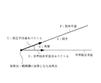
この誤差平面P(P1〜Pq)の概念を図3に示す。誤差平面Pを表すパラメータとしては、この誤差平面Pが、基準点の中で観測網の基準となる基準点を通る仮想的な水平面(基準誤差平面)となす角をα、その傾きをkとし、誤差平面P上のベクトルで基準誤差平面との角度がαとなる基本ベクトルを誤差平面基本ベクトルVとする。図4(a)にターゲット装置Tの誤差算出方法の一例を示す。誤差平面基本ベクトルVと対をなす基準誤差平面上の単位ベクトル(基準誤差平面基本ベクトル)をSとすると、任意の測定点(Xs,Ys)から基準誤差平面基本ベクトルSへの垂線に対応する位置誤差が求める測定点(Xs,Ys)の誤差となる。その処理をX,Y,Zの各方向の誤差について行うことにより、ターゲット装置Tの測定点(Xs,Ys)での誤差(ΔXt,ΔYt,ΔZt)を求めることができる。測定点での測位による位置データ(Xs,Ys,Zs)にこの誤差データ(ΔXt,ΔYt,ΔZt)を加えた、(Xs+ΔXt,Ys+ΔYt,Zs+ΔZt)が正確なターゲット装置Tの位置データとなる。
【0029】
このようにして誤差平面演算機140で求められた誤差平面P1〜Pqのパラメータは、送受信機150よりターゲット装置Tに送信される。ターゲット装置Tではこの誤差平面パラメータを送受信機200で受信して位置補正演算器230に入力する。位置補正演算器230にはGPSレシーバ220より、GPSアンテナ210で受信した航法メッセージを解読して求めた自身の位置情報も入力されている。位置補正演算器230はこの単独測位によって求めた自身の位置を、誤差平面パラメータから求めた誤差データによって補正し、補正された位置データを記憶装置240に格納する。
【0030】
以上のように、この実施の形態1によれば、例えば3つの基準点について、その位置と誤差のデータから誤差平面パラメータを求め、その3つの基準点を頂点とする三角形の中にある測定点の位置に対応する正確な誤差を求めて補正することにより、当該測定点の正確な位置データを求めることができるという効果が得られる。
【0031】
実施の形態2.
なお、上記実施の形態1では、基本的なGPSシステムによる位置検出の場合について説明したが、大規模なGPS広域システムによる位置検出に対応することも可能である。図5はそのようなこの発明の実施の形態2による位置検出システムを示す構成図である。図において、R1〜Rqは基準局、Cは計算機センタであり、T1,T2,…,Trはターゲット装置である。
【0032】
また、基準局R1〜Rq内の、1はGPSアンテナ、2はGPSレシーバ、3は送受信機である。計算機センタC内の、101〜10q,150は送受信機、111〜11qは誤差演算器、121〜12q,131〜13qは記憶装置、140は誤差平面演算器である。ターゲット装置T1〜Tr内の、200は送受信機、210はGPSアンテナ、220はGPSレシーバ、230は位置補正演算器である。なお、これら各部は図2に同一符号を付して示した、実施の形態1におけるそれらと同等のものである。
【0033】
計算機センタC内において、160は基準局R1〜Rqをグループ化して基準点の統合化を行う基準点統合化処理部である。また、各ターゲット装置T1〜Tr内において、250はそのターゲット装置T1〜Trが複数の誤差平面のうちどの誤差平面に属するかを判定する誤差平面識別処理部である。この実施の形態2の計算機センタCは上記基準点統合化処理部160を備えており、各ターゲット装置T1〜Trは上記誤差平面識別処理部250を備えている点で、図2に示した実施の形態1のそれらとは異なっている。
【0034】
次に動作について説明する。
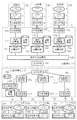
計算機センタCの各記憶装置131〜13qに誤差演算器111〜11qで計算された誤差データが格納されるまでは、実施の形態1の場合と同様に処理が進行する。広範囲なエリアに対応する大規模な広域GPSによる位置検出システムを構築する場合、基準点統合化処理部160は高精度なGPS測量を実現するために、図6に示すように基準局R1〜Ruの数を多くし、3つの基準局(R1,R2,R3),(R2,R3,R4),…をグルーピングしてそれぞれ観測網を構成する。ここで、このグルーピングされる基準局R1〜Ruの数は3局以上であればよく、3局に限られるものではない。誤差平面演算器140はそれら各観測網ごとに誤差平面P1〜Pvのパラメータを求め、送受信機150より各ターゲット装置T1〜Trに送信する。
【0035】
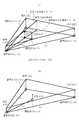
ここで、図4(a)を用いて誤差平面パラメータの求め方を説明する。
図4(a)は誤差平面パラメータの算出方法の一例を示す説明図であり、誤差平面を表現するベクトルと各観測網を構成する基準局中の1つ(図示の例では基準局0)を誤差平面の基準点とし、その位置座標値および誤差値を誤差平面パラメータとする。まず、各基準点の全てにおいて、その誤差が(ΔX0,ΔY0,ΔZ0)であるとした時の誤差平面について考える。つまり、(X0,Y0,ΔX0またはΔY0またはΔZ0)、(X1,Y1,ΔX0またはΔY0またはΔZ0)、(X2,Y2,ΔX0またはΔY0またはΔZ0)を通る平面を基準誤差平面とする。この基準誤差平面と誤差平面との交線に垂直で、基準点を通る基準誤差平面上のベクトルを基準誤差平面基本ベクトルSとする。また、基準誤差平面と誤差平面との交線と垂直で、基準点を通る誤差平面上のベクトルを誤差平面基本ベクトルVとする。
【0036】
ここで、測定点(ターゲット装置の位置)を(Xs,Ys)とすると、測定点(Xs,Ys)から基準誤差平面基本ベクトルSへの垂線の足をH0(Xh,Yh,ΔX0またはΔY0またはΔZ0)とすると、この垂線の足H0(Xh,Yh,ΔX0またはΔY0またはΔZ0)における誤差平面上の点(Xh,Yh,ΔXsまたはΔYsまたはΔZs)のZ軸の値=ΔXsまたはΔYsまたはΔZsが誤差になる。
【0037】
なお、複数の観測網のうち、ターゲット装置T1〜Trが属する観測網は、例えば、ターゲット装置T1〜Trの位置(Xs,Ys)における基準誤差平面上の点(Xs,Ys,ΔX0またはΔY0またはΔZ0)から基準誤差平面基本ベクトルSへの垂線の足H0(Xh,Yh,ΔX0またはΔY0またはΔZ0)までの距離が最も短い観測網とする。
【0038】
また、図4(b)は誤差平面パラメータの算出方法の他の一例を示す説明図であり、ここでは、3つの基準局0(X0,Y0)、基準局1(X1,Y1)、基準局2(X2,Y2)から観測点(Xs,Ys)の誤差ΔXsを、次の式を用いて線形演算により求める。
【0039】
【数1】

ここで、各基準局における誤差はそれぞれ(ΔX0,ΔY0,ΔZ0)、(ΔX1,ΔY1,ΔZ1)、(ΔX2,ΔY2,ΔZ2)であるとする。なお、この方法では、各基準局の位置座標値とその誤差が誤差平面パラメータとなる。
【0041】
各ターゲット装置T1〜Trでは、計算機センタCから送られてくる誤差平面パラメータをそれぞれの送受信機200で受信して、それを誤差平面識別処理部250に入力する。誤差平面識別処理部250はそのターゲット装置T1〜Trが複数の観測網(誤差平面)のうちどの観測網に属するかを判定し、該当する誤差平面パラメータを位置補正演算器230に送る。以下、実施の形態1の場合と同様に処理が進行して、各ターゲット装置T1〜Trの補正された位置データの計算が行われる。
【0042】
以上のように、この実施の形態2によれば、多数の基準局R1〜Ruをグループ化して複数の観測網を構成し、ターゲット装置T1〜Trがそのうちのどの観測網に対応するかを判断して、対応する観測網の誤差パラメータにより正確な誤差を求めているので、広範囲において精度よく各ターゲット装置T1〜Trの位置を算出することができるという効果が得られる。
【0043】
実施の形態3.
また、上記各実施の形態においては、遠隔地のターゲット装置の位置管理については触れていないが、遠隔地のターゲット装置の正確な位置管理を行うことも可能である。図7はそのようなこの発明の実施の形態3による位置検出システムを示す構成図である。なお、図中、相当部分には図2と同一符号を付してその説明を省略する。図において、Mは計算機センタCからの誤差平面パラメータを受信する機能、ターゲット装置T1〜Trからの単独測位結果を受信する機能、それら単独測位結果と誤差平面パラメータからターゲット装置T1〜Trの位置を計算する機能、およびターゲット装置T1〜Trの位置情報をターゲット装置T1〜Trに転送する機能を備えた位置管理センタである。
【0044】
この位置管理センタM内において、300は計算機センタCからの補正データ(誤差平面パラメータ)を受信する送受信機であり、311,312,…,31rは各ターゲット装置T1〜Trからの単独測位データを受信する送受信機である。321,322,…,32rは計算機センタCからの補正データとターゲット装置T1〜Trからの単独測位データから、ターゲット装置T1〜Trの現状の位置に対応した各ターゲット装置T1〜Trの正確な位置データを計算する位置補正演算器である。また、ターゲット装置T1〜Tr内において、260は単独測位のための演算処理を行う演算処理部であり、270はこの演算処理部260によって求められた単独測位結果を位置管理センタMに転送するための送受信機である。
【0045】
次に動作について説明する。
ここで、計算機センタCにおいて、各基準局R1〜Rqの誤差データが誤差演算器111〜11qによって計算され、誤差平面演算機140にてその誤差データから当該基準点における誤差平面を求め、得られた誤差平面パラメータを送受信機150から送信するまでの動作は、実施の形態1の場合と同様である。
【0046】
一方、各ターゲット装置T1〜Trは測位に必要な航法メッセージをGPSアンテナ210で受信してGPSレシーバ220にて解読する。解読結果は演算処理部260に送られて単独測位のための演算処理が行われ、得られた単独測位結果が送受信機270より位置管理センタMに転送される。
【0047】
位置管理センタMはこの計算機センタCから送られてくる誤差平面パラメータを、送受信機300にて補正データとして受信し、各ターゲット装置T1〜Trから送られてくる単独測位結果を、送受信機311〜31rにて受信する。なお、補正データは、図4(a)に示す算出方法によれば、誤差平面を表現するベクトルと各観測網を構成する基準局のうちの1つを誤差平面の基準点とし、その位置座標値および誤差値が誤差平面パラメータとなる。また図4(b)に示す計算方法では、各基準局の位置座標値とその誤差が誤差平面パラメータとなる。この誤差平面パラメータと単独測位結果をもとに、位置管理センタMの各位置補正演算器321〜32rは、対応する観測網の誤差平面パラメータから対応するターゲット装置T1〜Trの誤差を求め、正確なターゲット装置T1〜Trの位置を決定する。
【0048】
このようにして位置補正演算器321〜32rで決定された各ターゲット装置T1〜Trの位置情報は、送受信機311〜31rを介して対応するターゲット装置T1〜Trに送られる。これにより、ターゲット装置T1〜Trの正確な位置管理が可能となる。
【0049】
このように、この実施の形態3によれば、位置管理センタMを設けて、計算機センタCからの誤差平面パラメータと、各ターゲット装置T1〜Trからの単独測位結果をこの位置管理センタMに送り、位置管理センタMではその位置補正演算器321〜32rにおいて、それらをもとにターゲット装置T1〜Trの概略位置(単独測位結果)から複数の観測網を求めて位置情報を決定しているので、遠隔地にあるターゲット装置T1〜Trの位置を精度よく管理することが可能になるという効果が得られる。
【0050】
実施の形態4.
なお、上記実施の形態3では、基本的なGPSによる位置検出システムにおけるターゲット装置の位置管理について説明したが、実施の形態2で説明した大規模な広域GPSによる位置検出システムに対応することも可能である。図8はそのようなこの発明の実施の形態4による位置検出システムを示す構成図である。なお、図中、相当部分には図7と同一符号を付してその説明を省略する。
【0051】
また、計算機センタC内において、160は基準局R1〜Rqをグループ化して基準点の統合化を行う基準点統合化処理部であり、位置管理センタM内において、361,362,…,36rはそれぞれに対応づけられたターゲット装置T1〜Trが、複数の誤差平面のうちどの誤差平面に属するかを判定する誤差平面識別処理部である。なお、これらは図5に示した実施の形態2のそれらと同等のものであり、この実施の形態4は、計算機センタCが上記基準点統合化処理部160を、位置管理センタMが上記誤差平面識別処理部361〜36rを備えている点で、図7に示した実施の形態3とは異なっている。
【0052】
次に動作について説明する。
計算機センタCの各記憶装置131〜13qに誤差演算器111〜11qで計算された誤差データが格納されるまでの動作、および各ターゲット装置T1〜Trの送受信機270より単独測位結果が位置管理センタMに転送されるまでの動作は、実施の形態3の場合と同様に処理が進行する。広範囲なエリアに対応する大規模な広域GPSによる位置検出システムを構築する場合、計算機センタCの基準点統合化処理部160は実施の形態2の場合と同様に、高精度なGPS測量を実現するため、基準局R1〜Rqをグルーピングして観測網を構成する。誤差平面演算器140はそれら各観測網ごとに誤差平面パラメータを求め、送受信機150より位置管理センタMに送信する。
【0053】
位置管理センタMはこの計算機センタCからの誤差平面パラメータを、補正データとしてその送受信機300によって受信する。また同時に、各ターゲット装置T1〜Trからの単独測位結果を送受信機311〜31rによって受信する。なお、上記補正データは実施の形態2の場合と同様に、図4(a)に示す方法では誤差平面を表現するベクトルと各観測網を構成する基準局のうち1局を誤差平面の基準点とし、その位置座標値および誤差値が誤差平面パラメータとなり、図4(b)に示す方法では各基準局の位置座標値とその誤差が誤差平面パラメータとなる。
【0054】
位置管理センタMの誤差平面判定処理部361〜36rは、この誤差平面パラメータと単独測位結果をもとに、ターゲット装置T1〜Trの位置に対応する観測網を決定し、さらに位置補正演算器321〜32rにより、対応する観測網の誤差平面パラメータから各ターゲット装置T1〜Trの誤差を求めて、正確なターゲット装置の位置を決定する。このようにして得られた各ターゲット装置T1〜Trの正確な位置は、送受信機311〜31rより対応するターゲット装置T1〜Trに送信される。
【0055】
このように、この実施の形態4によれば、基準局R1〜Rqをグループ化して複数の観測網を構成し、ターゲット装置T1〜Trが観測網に対応するかを判断し、誤差平面パラメータと単独測位結果をもとに、位置管理センタMの位置補正演算器321〜32rにて各ターゲット装置T1〜Trの位置情報を決定しているので、広域のGPSシステムにおいても、ターゲット装置T1〜Trの位置を精度よく管理することが可能になるという効果が得られる。
【0056】
実施の形態5.
なお、上記実施の形態3および実施の形態4では、位置管理センタM内において、決定された各ターゲット装置T1〜Trの位置情報の表示については言及していなかったが、決定されたターゲット装置T1〜Trの位置情報を地図データ上に表示するようにすることも可能である。図9はそのようなこの発明の実施の形態5による位置検出システムを示す構成図である。なお、図中、相当部分には図7と同一符号を付してその説明を省略する。
【0057】
図において、330は各ターゲット装置T1〜Trの位置、および地図データが表示される表示器であり、340はその地図データが格納された記憶装置である。350は各位置補正演算器321〜32rの演算結果に基づいて、表示器330の画面に記憶装置340から読み出した所定の地図データを表示するとともに、表示された地図データ上にターゲット装置T1〜Trの位置をプロットする表示処理装置である。
【0058】
次に動作について説明する。
なお、位置管理センタMの位置補正演算器321〜32rによって、各ターゲット装置T1〜Trの正確な位置を決定するまでの動作は実施の形態3の場合と同様である。位置補正演算器321〜32rにて決定された各ターゲット装置T1〜Trの位置情報は、位置管理センタM内の表示処理装置350に送られる。表示処理装置350は受け取った各ターゲット装置T1〜Trの位置情報に基づいて記憶装置340より所定の地図データを読み出し、それを表示器330の画面に表示する。そして、その表示器330に表示された地図データ上に、各ターゲット装置T1〜Trの位置をプロットする。これにより、ターゲット装置T1〜Trの正確な位置管理が可能となる。
【0059】
ここで、記憶装置340には地図データとして、例えば航空写真からその中の基準点により位置を正規化した地図画像データが貯えられる。この地図画像データは、航空写真のカメラの光学系の歪み、航空写真の撮影の位置による歪みがあらかじめ取り除かれている。さらに地図画像データの画像内の基準点をGPSにより測定し、画像を座標系にマッピングすることにより、地図画像データと位置座標との関係が分かり、この地図画像データを地図データとして使用することが可能となる。
【0060】
また、表示器330に表示された地図データ上に、各ターゲット装置T1〜Trの位置をプロットする場合、上記画像と座標系との対応関係により、GPSによって得られた位置情報から、その位置に対応した地図画像データを記憶装置340から表示処理装置350により取り出して、ターゲット装置T1〜Trの位置を示すマーカーとともに表示器330の画面上に表示する。
【0061】
なお、上記説明では、実施の形態3による位置検出システムに適用した場合について述べたが、実施の形態4による位置検出システムにも適用可能であることはいうまでもない。
【0062】
以上のように、この実施の形態5によれば、ターゲット装置T1〜Trにおける単独測位結果を位置管理センタMに送り、位置管理センタMで各ターゲット装置T1〜Trの概略位置から複数の観測網を決定して求めた、ターゲット装置T1〜Trの位置を表示器330に表示しているので、中央に配置された位置管理センタMにおいて、複数存在するターゲット装置T1〜Trの現状の位置を集中的に管理することが可能なマンマシンインタフェースを提供することができるという効果が得られる。
【0063】
実施の形態6.
次に、この発明の実施の形態6として、上記実施の形態2および実施の形態4による位置検出システムで用いられた補正データについて説明する。図10はその補正データのフォーマットを示す説明図である。この補正データとしては、複数の基準局の少なくとも3局ずつ以上を1まとまりとしてグループ化して形成された観測網毎に、それぞれの誤差平面を表す誤差平面パラメータが用いられている。図示の補正データのフォーマットでは、まず観測網の数が規定され、次に第1〜第vの観測網のそれぞれについて、基準点の座標値、誤差平面の傾き、誤差平面基準ベクトルによる誤差平面パラメータが規定されている。ターゲット装置はこの補正データを受信し、そのデータフォーマットに従って自身の位置に対応する補正データを得ることができる。このようにして、大規模なGPSシステムにおいても、効率良く補正データをターゲット装置あるいは位置管理センタに供給することが可能になる。
【0064】
【発明の効果】
以上のように、この発明によれば、あらかじめ絶対位置が確定している複数の基準局からの絶対位置と、各基準局がGPS衛星より受信した航法メッセージから計算した自身の位置との差を誤差データとし、それら複数の基準局における誤差データから誤差平面を求めて、その誤差平面を表す誤差平面パラメータを補正データとして計算機センタよりターゲット装置に送信し、ターゲット装置ではGPS衛星より受信した航法メッセージによる単独測位結果にて得られた自身の位置の誤差を、上記誤差平面パラメータを用いて補正するように構成したので、ターゲット装置の位置に対応した誤差を高精度に求めることができ、またその誤差を用いて測定点の正確な位置データを求めることが可能な位置検出システムが得られる効果がある。
【0065】
この発明によれば、基準局をグループ化して複数の観測網を形成し、それら各観測網において、それぞれの観測網毎に誤差平面パラメータを求め、それをターゲット装置に補正データとして送信し、ターゲット装置において単独測位結果からの自身の位置における誤差を、その誤差平面パラメータから求めて、単独測位による位置を補正するように構成したので、広い範囲において、散在するターゲット装置の位置検出を高精度に行うことが可能になるという効果がある。
【0066】
この発明によれば、位置管理センタを設けて、計算機センタからは誤差平面パラメータを、ターゲット装置からは単独測位結果をそれぞれ受信して、それら単独測位結果と誤差平面パラメータからターゲット装置の位置を計算し、得られたターゲット装置の位置情報をターゲット装置に転送するとともに、各ターゲット装置より、GPS衛星から受信した測位に必要な航法メッセージによる単独測位結果を、位置管理センタに転送するように構成したので、遠隔地に散在するターゲット装置の位置を高精度で管理することができる位置検出システムが得られる効果がある。
【0067】
この発明によれば、基準局をグループ化して形成した複数の観測網毎に誤差平面パラメータを求めてそれを補正データとして位置管理センタに送信し、位置管理センタでは、その誤差平面パラメータにより、ターゲット装置から受信した当該ターゲット装置における単独測位データからターゲット装置の位置の誤差を求めて、この単独測位により求めたターゲット装置の位置を補正するように構成したので、広い範囲において、散在するターゲット装置の位置を高精度に管理することが可能になるという効果がある。
【0068】
この発明によれば、ターゲット装置の測位結果から、位置管理センタの表示器に、ターゲット装置の位置を含む地図を表示するように構成したので、存在する複数のターゲット装置の現状の位置を、集中的に管理することが可能になるという効果がある。
【0069】
この発明によれば、補正データを、複数の基準局の少なくとも3局以上を1まとまりとする誤差平面を表す誤差平面パラメータとするように構成したので、大規模なGPSシステムによる位置検出システムにおいて、効率良く補正データをターゲット装置あるいは位置管理センタに供給することが可能になるという効果がある。
【図面の簡単な説明】
【図1】 この発明による位置検出システムの概念を示す構成図である。
【図2】 この発明の実施の形態1による位置検出システムを示す構成図である。
【図3】 この発明における誤差平面の概念を示す説明図である。
【図4】 この発明における補正データ算出方法を示す説明図である。
【図5】 この発明の実施の形態2による位置検出システムを示す構成図である。
【図6】 この発明の実施の形態2および実施の形態4における観測網の構成を示す説明図である。
【図7】 この発明の実施の形態3による位置検出システムを示す構成図である。
【図8】 この発明の実施の形態4による位置検出システムを示す構成図である。
【図9】 この発明の実施の形態5による位置検出システムを示す構成図である。
【図10】 この発明の実施の形態6における補正データのフォーマットを示す説明図である。
【図11】 従来のGPSによる位置検出システムの一例を示す構成図である。
【符号の説明】
C 計算機センタ、M 位置管理センタ、R1〜Rq 基準局、S1〜Sp GPS衛星、T,T1〜Tr ターゲット装置、1 GPSアンテナ、2 GPSレシーバ、3 送受信機、101〜10q 送受信機、111〜11q 誤差演算器、121〜12q 記憶装置、131〜13q 記憶装置、140 誤差平面演算器、150 送受信機、160 基準点統合化処理部、200 送受信機、210 GPSアンテナ、220 GPSレシーバ、230 位置補正演算器、240 記憶装置、250 誤差平面識別処理部、260 演算処理部、270 送受信機、300 送受信機、311〜31r 送受信機、321〜32r 位置補正演算器、330 表示器、340 記憶装置、350 表示処理装置。[0001]
BACKGROUND OF THE INVENTION
The present invention relates to a position detection system for measuring its own absolute position using a GPS (Global Positioning System), and more particularly to a position detection system capable of highly accurate positioning in a wide area.
[0002]
[Prior art]
FIG. 11 is a block diagram showing the concept of a conventional position detection system, for example, disclosed in Japanese Patent Laid-Open No. 8-129062, which locates its own position by GPS. In the figure, S is a GPS satellite, and A is a self-station capable of positioning itself using this GPS satellite S. B1, B2,..., Bn are errors (ΔX1, ΔY1, ΔZ1), (ΔX2, ΔY2, ΔZ2),..., (ΔXn, ΔYn, ΔZn) between their true positions known in advance and GPS measured values, respectively. ), And one of the reference stations (for example, the reference station B1) averages the errors (ΔX1, ΔY1, ΔZ1) to (ΔXn, ΔYn, ΔZn), and the self position measured by the own station A Correction values (ΔXs, ΔYs, ΔZs) for correcting (X0, Y0, Z0) are generated.
[0003]
In the own station A,
[0004]
Further, in each of the reference stations B1 to Bn,
[0005]
The
[0006]
Next, the operation will be described.
The own station A uses the
[0007]
Upon receiving this request, the reference station B1 measures its own position data (X1, Y1, Z1) using the built-in
[0008]
When each of the reference stations B2 to Bn receives this request by the
[0009]
In the reference station B1, error data (ΔX2, ΔY2, ΔZ2) to (ΔXn, ΔYn, ΔZn) from the other reference stations B2 to Bn are received by the transmitter /
[0010]
In the own station A, the correction data (ΔXs, ΔYs, ΔZs) from the
[0011]
In addition to this, as a document having a description related to such a conventional position detection system, for example, JP-A-10-62514, JP-A-9-61509, JP-A-9-72951, etc. There is.
[0012]
[Problems to be solved by the invention]
Since the conventional position detection system is configured as described above, the measurement position of the own station A is corrected based on the correction value obtained by averaging the errors between the positions of the reference stations B1 to Bn and the GPS measurement values. Accordingly, the correction amount linearly changes inside the polygon connecting the plurality of reference stations B1 to Bn, and the error is averaged in one reference station, for example, the reference station B1. In this method, it is difficult to completely remove the error, and there is a problem that the error still exists.
[0013]
In addition, when it is realized in a wide area, it is necessary to configure a plurality of groups of reference stations B1 to Bn for obtaining correction values. However, the conventional method cannot cope with this, and further, the position of the own station A is set to the center side ( In the example of FIG. 11, there is a problem that one reference station, for example, the reference station B1), which calculates the correction value by averaging the errors, has no means of knowing it and cannot manage the position on the center side. .
[0014]
This invention was made in order to solve the above problems, can perform position detection in a wide area with high accuracy, and can manage the position of the target device (self station) on the center side. An object is to obtain a position detection system using GPS.
[0015]
[Means for Solving the Problems]
A position detection system according to the present invention includes: A plurality of reference stations having a function of receiving GPS satellite information necessary for positioning including a navigation message from a GPS satellite, the absolute position of which is determined in advance, and a reference based on a reference station as a reference among the plurality of reference stations Reference error planes, which are virtual horizontal planes passing through the points, are set for each of the three axes, and the positions of the respective reference stations are calculated based on GPS satellite information including navigation messages received by the respective reference stations, and are found in advance. An error plane for each of the reference error planes is obtained for each of the three axes from the absolute positions of the plurality of reference stations and the measured values at the plurality of reference stations, and a reference coordinate value of an arbitrary reference point and an arbitrary reference point Error plane parameters composed of error values measured using GPS and a vector that is the angle formed by the error plane with respect to the reference error plane are corrected. Data from the computer center, a function for receiving GPS satellite information necessary for positioning including navigation messages from the GPS satellites, a function for receiving error plane parameters transmitted by the computer center, and a single positioning result. An error at its own position is obtained from an error plane parameter from the computer center, and a target device having a function of correcting the position obtained by the independent positioning is provided. Is.
[0016]
In the position detection system according to the present invention, a plurality of observation networks are formed by grouping reference stations, an error plane parameter is obtained for each observation network, and is transmitted to the target device as correction data. Thus, an error in its own position from the single positioning result is obtained, and the position is corrected by single positioning.
[0017]
The position detection system according to the present invention has a function of receiving an error plane parameter from a computer center, a function of receiving a single positioning result from a target device, a function of calculating a position of the target device from a single positioning result and an error plane parameter, In addition, a position management center having a function of transferring position information of the target device to the target device is provided, a function of receiving a navigation message necessary for positioning from each GPS device, and a single positioning result to the position management center. It has a function to transfer.
[0018]
A position detection system according to the present invention includes: A plurality of reference stations having a function of receiving GPS satellite information necessary for positioning including a navigation message from a GPS satellite, the absolute position of which is determined in advance, and a reference based on a reference station as a reference among the plurality of reference stations Reference error planes, which are virtual horizontal planes passing through the points, are set for each of the three axes, and the positions of the respective reference stations are calculated based on GPS satellite information including navigation messages received by the respective reference stations, and are found in advance. An error plane for each of the reference error planes is obtained for each of the three axes from the absolute positions of the plurality of reference stations and the measured values at the plurality of reference stations, and a reference coordinate value of an arbitrary reference point and an arbitrary reference point Error plane parameters composed of error values measured using GPS and a vector that is the angle formed by the error plane with respect to the reference error plane are corrected. A plurality of target devices having a function of receiving a GPS satellite information necessary for positioning including a navigation message from the GPS satellite, and a function of transmitting a single positioning result based thereon. A function of receiving the error plane parameter transmitted by the center, a function of receiving the single positioning result transmitted by the target device, a function of calculating the position of the target device from the single positioning result and the error plane parameter, and the target device A location management center having a function of transferring location information to the target device. Is.
[0019]
The position detection system according to the present invention displays a map including the position of the target device from the error plane parameter and the single positioning result in the position management center.
[0020]
In the position detection system according to the present invention, an error plane parameter representing an error plane in which at least three or more of a plurality of reference stations are grouped is used as correction data.
[0021]
DETAILED DESCRIPTION OF THE INVENTION
An embodiment of the present invention will be described below.
FIG. 1 is a block diagram showing the concept of a position detection system according to the present invention. In the figure, S1, S2,..., Sp are GPS satellites that transmit GPS satellite information necessary for positioning including navigation messages. R1, R2,..., Rq are arranged at reference points and their absolute positions are determined in advance, and have a function of receiving GPS satellite information necessary for positioning including navigation messages from the GPS satellites S1 to Sp. The reference station. C calculates the position of each of the reference stations R1 to Rq based on the GPS satellite information including the navigation message from each of the reference stations R1 to Rq, and the calculation result and the absolute position of the reference stations R1 to Rq that are known in advance. Is a computer center that obtains an error plane from error data at a plurality of reference stations R1 to Rq using the difference between the error plane and error plane parameters representing the error plane as correction data. T1, T2,..., Tr are GPS satellite information receiving functions necessary for positioning including navigation messages from GPS satellites S1 to Sp, an error plane parameter receiving function from computer center C, and an independent position error. This is a target device that has a function of obtaining the error plane parameter from the result and correcting it with the error plane parameter of the position obtained by independent positioning, and measuring the position.
[0022]
FIG. 2 is a block diagram showing a basic system of a position detection system using GPS according to the first embodiment. In the figure, R1, R2,..., Rq are reference stations, C is a computer center, and T is a target device, which are equivalent to the corresponding parts shown in FIG. In each of the reference stations R1 to Rq,
[0023]
In the computer center C,
[0024]
Further, in the target device T, 200 is a transceiver that receives the error plane parameter sent from the computer center C, and 210 receives a navigation message at the current position of the target device T from the GPS satellites S1 to Sp. GPS antenna. A
[0025]
Next, the operation will be described.
First, a plurality of reference stations R1 to Rq are installed in advance, and their absolute positions (Xs1, Ys1, Zs1) to (Xsq, Ysq, Zsq) are measured. Although this position measurement requires a long time measurement, the absolute position can be measured by using static GPS. A conventional triangulation method is also possible. As a result of the position measurement of each reference station R1 to Rq, the absolute position data (Xs1, Ys1, Zs1) to (Xsq, Ysq, Zsq) are used for the position data corresponding to the respective reference stations R1 to Rq in the computer center C. It memorize | stores in the memory | storage devices 121-12q.
[0026]
Thereafter, the operation of the position detection system is started. Each of the reference stations R1 to Rq periodically receives a navigation message at each reference point via its
[0027]
The
[0028]
The concept of this error plane P (P1 to Pq) is shown in FIG. As parameters representing the error plane P, an angle formed by the error plane P and a virtual horizontal plane (reference error plane) passing through a reference point serving as a reference of the observation network among the reference points is α, and an inclination thereof is k. A basic vector having an angle α with respect to the reference error plane and a vector on the error plane P is defined as an error plane basic vector V. FIG. 4A shows an example of an error calculation method of the target device T. If a unit vector (reference error plane basic vector) on the reference error plane paired with the error plane basic vector V is S, it corresponds to a perpendicular line from an arbitrary measurement point (Xs, Ys) to the reference error plane basic vector S. The position error is an error of the measurement point (Xs, Ys) to be obtained. By performing this process for errors in the X, Y, and Z directions, errors (ΔXt, ΔYt, ΔZt) at the measurement points (Xs, Ys) of the target device T can be obtained. (Xs + ΔXt, Ys + ΔYt, Zs + ΔZt) obtained by adding the error data (ΔXt, ΔYt, ΔZt) to the position data (Xs, Ys, Zs) obtained by positioning at the measurement point becomes the accurate position data of the target device T.
[0029]
The parameters of the error planes P1 to Pq obtained in this way by the
[0030]
As described above, according to the first embodiment, for example, for three reference points, an error plane parameter is obtained from the position and error data, and the measurement points are in a triangle having the three reference points as vertices. By obtaining and correcting an accurate error corresponding to the position, it is possible to obtain an effect that accurate position data of the measurement point can be obtained.
[0031]
In the first embodiment, the case of position detection by a basic GPS system has been described. However, position detection by a large-scale GPS wide area system can also be supported. FIG. 5 is a block diagram showing such a position detection system according to the second embodiment of the present invention. In the figure, R1 to Rq are reference stations, C is a computer center, and T1, T2,..., Tr are target devices.
[0032]
In the reference stations R1 to Rq, 1 is a GPS antenna, 2 is a GPS receiver, and 3 is a transceiver. In the computer center C, 101 to 10q and 150 are transceivers, 111 to 11q are error calculators, 121 to 12q and 131 to 13q are storage devices, and 140 is an error plane calculator. In the target devices T1 to Tr, 200 is a transceiver, 210 is a GPS antenna, 220 is a GPS receiver, and 230 is a position correction calculator. These parts are the same as those in the first embodiment shown in FIG.
[0033]
In the computer center C,
[0034]
Next, the operation will be described.
Until the error data calculated by the
[0035]
Here, how to obtain the error plane parameter will be described with reference to FIG.
FIG. 4A is an explanatory diagram showing an example of a method for calculating an error plane parameter. A vector expressing the error plane and one of the reference stations constituting each observation network (reference station 0 in the illustrated example) are error planes. And the position coordinate value and the error value as error plane parameters. First, consider the error plane when the error is (ΔX0, ΔY0, ΔZ0) at all the reference points. That is, a plane passing through (X0, Y0, ΔX0 or ΔY0 or ΔZ0), (X1, Y1, ΔX0 or ΔY0 or ΔZ0), (X2, Y2, ΔX0 or ΔY0 or ΔZ0) is set as a reference error plane. A vector on the reference error plane perpendicular to the intersection line of the reference error plane and the error plane and passing through the reference point is set as a reference error plane basic vector S. A vector on the error plane that is perpendicular to the intersection line between the reference error plane and the error plane and passes through the reference point is defined as an error plane basic vector V.
[0036]
If the measurement point (target device position) is (Xs, Ys), the perpendicular foot from the measurement point (Xs, Ys) to the reference error plane basic vector S is represented by H0 (Xh, Yh, ΔX0 or ΔY0 or ΔZ0), the Z-axis value = ΔXs or ΔYs or ΔZs of the point (Xh, Yh, ΔXs or ΔYs or ΔZs) on the error plane at the foot H0 (Xh, Yh, ΔX0 or ΔY0 or ΔZ0) of this perpendicular line is It becomes an error.
[0037]
Of the plurality of observation networks, the observation network to which the target devices T1 to Tr belong is, for example, a point (Xs, Ys, ΔX0 or ΔY0 on the reference error plane at the position (Xs, Ys) of the target devices T1 to Tr. It is assumed that the observation network has the shortest distance from the vertical leg H0 (Xh, Yh, ΔX0 or ΔY0 or ΔZ0) to the reference error plane basic vector S from ΔZ0).
[0038]
FIG. 4B is an explanatory diagram showing another example of the method for calculating the error plane parameter. Here, three reference stations 0 (X0, Y0), reference station 1 (X1, Y1), and reference station 2 (X2). , Y2), an error ΔXs of the observation point (Xs, Ys) is obtained by linear calculation using the following equation.
[0039]
[Expression 1]
Here, it is assumed that the errors in each reference station are (ΔX0, ΔY0, ΔZ0), (ΔX1, ΔY1, ΔZ1), (ΔX2, ΔY2, ΔZ2), respectively. In this method, the position coordinate value of each reference station and its error are error plane parameters.
[0041]
In each target device T <b> 1 to Tr, the error plane parameter transmitted from the computer center C is received by each
[0042]
As described above, according to the second embodiment, a plurality of reference stations R1 to Ru are grouped to form a plurality of observation networks, and it is determined to which observation network the target devices T1 to Tr correspond. In addition, since an accurate error is obtained from the error parameter of the corresponding observation network, the effect that the position of each target device T1 to Tr can be calculated accurately in a wide range is obtained.
[0043]
In each of the above embodiments, the position management of the remote target device is not mentioned, but it is also possible to perform accurate position management of the remote target device. FIG. 7 is a block diagram showing such a position detection system according to
[0044]
In this position management center M,
[0045]
Next, the operation will be described.
Here, in the computer center C, the error data of the reference stations R1 to Rq are calculated by the
[0046]
On the other hand, each target device T1 to Tr receives a navigation message necessary for positioning by the
[0047]
The position management center M receives the error plane parameter sent from the computer center C as correction data by the
[0048]
The position information of the target devices T1 to Tr determined by the position correction calculators 321 to 32r in this way is sent to the corresponding target devices T1 to Tr via the transceivers 311 to 31r. Thereby, accurate position management of the target devices T1 to Tr is possible.
[0049]
As described above, according to the third embodiment, the position management center M is provided, and the error plane parameters from the computer center C and the independent positioning results from the target devices T1 to Tr are sent to the position management center M. In the position management center M, the position correction calculators 321 to 32r determine position information by obtaining a plurality of observation networks from the approximate positions (single positioning results) of the target devices T1 to Tr based on them. Thus, it is possible to obtain an effect that the positions of the target devices T1 to Tr at remote locations can be managed with high accuracy.
[0050]
Embodiment 4 FIG.
In the third embodiment, the position management of the target device in the basic GPS position detection system has been described. However, the position management system using the large-scale wide-area GPS described in the second embodiment can be used. It is. FIG. 8 is a block diagram showing such a position detection system according to Embodiment 4 of the present invention. In the figure, corresponding parts are denoted by the same reference numerals as those in FIG.
[0051]
In the computer center C,
[0052]
Next, the operation will be described.
The operation until the error data calculated by the
[0053]
The position management center M receives the error plane parameter from the computer center C by the
[0054]
The error plane
[0055]
As described above, according to the fourth embodiment, the reference stations R1 to Rq are grouped to form a plurality of observation networks, it is determined whether the target devices T1 to Tr correspond to the observation network, and the error plane parameter and the independent station parameter are independently used. Since the position correction calculators 321 to 32r of the position management center M determine the position information of each target device T1 to Tr based on the positioning result, even in a wide-area GPS system, An effect is obtained that the position can be managed with high accuracy.
[0056]
Embodiment 5 FIG.
In the third embodiment and the fourth embodiment, the display of the position information of each determined target device T1 to Tr in the position management center M is not mentioned, but the determined target device T1. It is also possible to display the position information of .about.Tr on the map data. FIG. 9 is a block diagram showing such a position detection system according to Embodiment 5 of the present invention. In the figure, corresponding parts are denoted by the same reference numerals as those in FIG.
[0057]
In the figure, 330 is a display for displaying the position of each target device T1 to Tr and map data, and 340 is a storage device for storing the map data. 350 displays the predetermined map data read from the
[0058]
Next, the operation will be described.
Note that the operations until the accurate positions of the target devices T1 to Tr are determined by the position correction calculators 321 to 32r of the position management center M are the same as those in the third embodiment. The position information of the target devices T1 to Tr determined by the position correction calculators 321 to 32r is sent to the
[0059]
Here, the
[0060]
Further, when plotting the positions of the target devices T1 to Tr on the map data displayed on the
[0061]
In the above description, the case where the present invention is applied to the position detection system according to the third embodiment has been described. Needless to say, the present invention can also be applied to the position detection system according to the fourth embodiment.
[0062]
As described above, according to the fifth embodiment, the single positioning results in the target devices T1 to Tr are sent to the position management center M, and a plurality of observation networks are transmitted from the approximate positions of the target devices T1 to Tr at the position management center M. Since the positions of the target devices T1 to Tr obtained by determining the position are displayed on the
[0063]
Embodiment 6 FIG.
Next, as Embodiment 6 of the present invention, correction data used in the position detection system according to
[0064]
【The invention's effect】
As described above, according to the present invention, the difference between the absolute position from a plurality of reference stations whose absolute positions are determined in advance and the own position calculated from the navigation message received by each reference station from the GPS satellite is obtained as error data. The error plane is obtained from the error data at the plurality of reference stations, the error plane parameter representing the error plane is transmitted as correction data from the computer center to the target device, and the target device performs single positioning by the navigation message received from the GPS satellite. Since the error of its own position obtained as a result is corrected using the above error plane parameter, the error corresponding to the position of the target device can be obtained with high accuracy, and the error is used. Thus, there is an effect that a position detection system capable of obtaining accurate position data of the measurement point is obtained.
[0065]
According to the present invention, the reference stations are grouped to form a plurality of observation networks, and in each of these observation networks, an error plane parameter is obtained for each observation network, and is transmitted as correction data to the target device. In this case, the error in the own position from the single positioning result is obtained from the error plane parameter, and the position by the single positioning is corrected, so that the positions of the scattered target devices are detected with high accuracy in a wide range. There is an effect that it becomes possible.
[0066]
According to the present invention, the position management center is provided, the error plane parameter is received from the computer center, and the single positioning result is received from the target device, and the position of the target device is calculated from the single positioning result and the error plane parameter. In addition to transferring the obtained target device position information to the target device, each target device is configured to transfer a single positioning result by a navigation message necessary for positioning received from a GPS satellite to the position management center. Therefore, there is an effect that a position detection system capable of managing the positions of target devices scattered in a remote place with high accuracy can be obtained.
[0067]
According to the present invention, an error plane parameter is obtained for each of a plurality of observation networks formed by grouping reference stations, and is transmitted as correction data to the position management center. The position management center uses the error plane parameter to determine the target device. Since the error of the position of the target device is obtained from the single positioning data received from the target device and the position of the target device obtained by the single positioning is corrected, the positions of the target devices scattered in a wide range It is possible to manage the image with high accuracy.
[0068]
According to this invention, since the map including the position of the target device is displayed on the indicator of the position management center from the positioning result of the target device, the current positions of the plurality of target devices existing are concentrated. There is an effect that it becomes possible to manage it.
[0069]
According to the present invention, since the correction data is configured to be an error plane parameter that represents an error plane in which at least three or more of the plurality of reference stations are grouped together, in the position detection system using a large-scale GPS system, the efficiency is improved. There is an effect that the correction data can be well supplied to the target device or the position management center.
[Brief description of the drawings]
FIG. 1 is a configuration diagram showing the concept of a position detection system according to the present invention.
FIG. 2 is a block diagram showing a position detection system according to
FIG. 3 is an explanatory diagram showing a concept of an error plane in the present invention.
FIG. 4 is an explanatory diagram showing a correction data calculation method according to the present invention.
FIG. 5 is a block diagram showing a position detection system according to
FIG. 6 is an explanatory diagram showing a configuration of an observation network according to
FIG. 7 is a block diagram showing a position detection system according to
FIG. 8 is a configuration diagram showing a position detection system according to a fourth embodiment of the present invention.
FIG. 9 is a block diagram showing a position detection system according to a fifth embodiment of the present invention.
FIG. 10 is an explanatory diagram showing a format of correction data according to Embodiment 6 of the present invention.
FIG. 11 is a configuration diagram showing an example of a conventional position detection system using GPS.
[Explanation of symbols]
C computer center, M position management center, R1-Rq reference station, S1-Sp GPS satellite, T, T1-Tr target device, 1 GPS antenna, 2 GPS receiver, 3 transceiver, 101-10q transceiver, 111-11q error Computing unit, 121-12q storage device, 131-13q storage device, 140 error plane computing unit, 150 transceiver, 160 reference point integration processing unit, 200 transceiver, 210 GPS antenna, 220 GPS receiver, 230 position correction computing unit , 240 storage device, 250 error plane identification processing unit, 260 computation processing unit, 270 transceiver, 300 transceiver, 311 to 31r transceiver, 321-32r position correction computing unit, 330 display, 340 storage device, 350 display processing apparatus.
Claims (6)
前記複数の基準局のうち基準となる基準局を基準とした基準点を通る仮想的な水平面である基準誤差平面を3軸に対しそれぞれ設定し、前記各基準局で受信された航法メッセージを含むGPS衛星情報をもとにそれぞれの基準局の位置を計算し、あらかじめ判明している当該複数の基準局の絶対位置と複数の基準局における測定値から、前記各基準誤差平面に対する誤差平面を3軸に対しそれぞれ求め、任意の基準点の基準座標値、前記任意の基準点におけるGPSを用いて測定した誤差値及び基準誤差平面に対し誤差平面がなす角度となるベクトルから構成される誤差平面パラメータを補正データとして送信する計算機センタと、
前記GPS衛星からの航法メッセージを含む測位に必要なGPS衛星情報を受信する機能、前記計算機センタが送信した誤差平面パラメータを受信する機能、および単独測位結果からの自身の位置における誤差を前記計算機センタからの誤差平面パラメータより求め、その単独測位により求めた位置の補正を行う機能を有するターゲット装置とを備えた位置検出システム。A plurality of reference stations having a function of receiving GPS satellite information necessary for positioning including navigation messages from GPS satellites, and whose absolute positions are determined in advance,
GPS satellite information including a navigation message received by each reference station, with reference error planes, which are virtual horizontal planes passing through a reference point based on a reference station serving as a reference among the plurality of reference stations, set for each of the three axes. the calculated position of each base station on the basis of the measured values in the absolute position and a plurality of reference stations of the plurality of reference stations that are known in advance, respectively determined with respect to three axes of the error plane with respect to the respective reference error plane, An error plane parameter composed of a reference coordinate value of an arbitrary reference point, an error value measured using GPS at the arbitrary reference point, and a vector that is an angle formed by the error plane with respect to the reference error plane is transmitted as correction data. A computer center,
A function for receiving GPS satellite information necessary for positioning including a navigation message from the GPS satellite, a function for receiving an error plane parameter transmitted by the computer center, and an error at its own position from a single positioning result. And a target device having a function of correcting the position obtained by the independent positioning obtained from the error plane parameter from
ターゲット装置が、単独測位結果からの自身の位置における誤差を前記計算機センタからの誤差平面パラメータより求めて、単独測位によって求めた自身の位置を補正する機能を有するものであることを特徴とする請求項1記載の位置検出システム。The computer center has a function of grouping at least three reference stations to form a plurality of observation networks, obtaining an error plane parameter in each of the observation networks, and transmitting it as correction data,
The target device has a function of obtaining an error in its own position from a single positioning result from an error plane parameter from the computer center, and correcting the position obtained by the single positioning. Item 2. The position detection system according to Item 1.
前記複数の基準局のうち基準となる基準局を基準とした基準点を通る仮想的な水平面である基準誤差平面を3軸に対しそれぞれ設定し、前記各基準局で受信された航法メッセージを含むGPS衛星情報をもとにそれぞれの基準局の位置を計算し、あらかじめ判明している当該複数の基準局の絶対位置と複数の基準局における測定値から、前記各基準誤差平面に対する誤差平面を3軸に対しそれぞれ求め、任意の基準点の基準座標値、前記任意の基準点におけるGPSを用いて測定した誤差値及び基準誤差平面に対し誤差平面がなす角度となるベクトルから構成される誤差平面パラメータを補正データとして送信する計算機センタと、
前記GPS衛星からの航法メッセージを含む測位に必要なGPS衛星情報を受信する機能、およびそれに基づく単独測位結果を送信する機能を有する複数のターゲット装置と、
前記計算機センタの送信した誤差平面パラメータを受信する機能、前記ターゲット装置の送信する単独測位結果を受信する機能、これら単独測位結果と誤差平面パラメータから前記ターゲット装置の位置を計算する機能、および前記ターゲット装置の位置情報を当該ターゲット装置に転送する機能を有する位置管理センタとを備えた位置検出システム。A plurality of reference stations having a function of receiving GPS satellite information necessary for positioning including navigation messages from GPS satellites, and whose absolute positions are determined in advance,
GPS satellite information including a navigation message received by each reference station, with reference error planes, which are virtual horizontal planes passing through a reference point based on a reference station serving as a reference among the plurality of reference stations, set for each of the three axes. the calculated position of each base station on the basis of the measured values in the absolute position and a plurality of reference stations of the plurality of reference stations that are known in advance, respectively determined with respect to three axes of the error plane with respect to the respective reference error plane, An error plane parameter composed of a reference coordinate value of an arbitrary reference point, an error value measured using GPS at the arbitrary reference point, and a vector that is an angle formed by the error plane with respect to the reference error plane is transmitted as correction data. A computer center,
A plurality of target devices having a function of receiving GPS satellite information necessary for positioning including a navigation message from the GPS satellite, and a function of transmitting a single positioning result based thereon;
A function of receiving the error plane parameter transmitted from the computer center, a function of receiving the single positioning result transmitted from the target device, a function of calculating the position of the target device from the single positioning result and the error plane parameter, and the target A position detection system comprising: a position management center having a function of transferring apparatus position information to the target apparatus.
位置管理センタが、ターゲット装置の位置における誤差を、当該ターゲット装置から受信した当該ターゲット装置における単独測位データと、前記計算機センタからの誤差平面パラメータより求め、単独測位によって求めた前記ターゲット装置の位置を補正する機能を有することを特徴とする請求項3記載の位置検出システム。The computer center has a function of grouping at least three reference stations to form a plurality of observation networks, and obtaining an error plane parameter in each of the observation networks,
The position management center obtains the error in the position of the target device from the single positioning data in the target device received from the target device and the error plane parameter from the computer center, and determines the position of the target device obtained by the single positioning. The position detection system according to claim 3, wherein the position detection system has a correction function.
Priority Applications (1)
| Application Number | Priority Date | Filing Date | Title |
|---|---|---|---|
| JP2000040135A JP4330752B2 (en) | 2000-02-17 | 2000-02-17 | Position detection system, computer center, target device, and position management center |
Applications Claiming Priority (1)
| Application Number | Priority Date | Filing Date | Title |
|---|---|---|---|
| JP2000040135A JP4330752B2 (en) | 2000-02-17 | 2000-02-17 | Position detection system, computer center, target device, and position management center |
Publications (3)
| Publication Number | Publication Date |
|---|---|
| JP2001228234A JP2001228234A (en) | 2001-08-24 |
| JP2001228234A5 JP2001228234A5 (en) | 2007-03-15 |
| JP4330752B2 true JP4330752B2 (en) | 2009-09-16 |
Family
ID=18563576
Family Applications (1)
| Application Number | Title | Priority Date | Filing Date |
|---|---|---|---|
| JP2000040135A Expired - Lifetime JP4330752B2 (en) | 2000-02-17 | 2000-02-17 | Position detection system, computer center, target device, and position management center |
Country Status (1)
| Country | Link |
|---|---|
| JP (1) | JP4330752B2 (en) |
Families Citing this family (3)
| Publication number | Priority date | Publication date | Assignee | Title |
|---|---|---|---|---|
| JP2004144709A (en) * | 2002-10-28 | 2004-05-20 | Mitsubishi Electric Corp | Moving body terminal and center station |
| JP2013195083A (en) * | 2012-03-15 | 2013-09-30 | Pasuko:Kk | Position measuring system |
| CN114185069B (en) * | 2021-12-07 | 2022-09-09 | 西藏金采科技股份有限公司 | Differential positioning method, device and system for improving Beidou positioning accuracy |
-
2000
- 2000-02-17 JP JP2000040135A patent/JP4330752B2/en not_active Expired - Lifetime
Also Published As
| Publication number | Publication date |
|---|---|
| JP2001228234A (en) | 2001-08-24 |
Similar Documents
| Publication | Publication Date | Title |
|---|---|---|
| US10798526B2 (en) | Systems and methods for co-localization of multiple devices | |
| EP2902748B1 (en) | Vehicle position calibration method and corresponding apparatus | |
| CN108917758B (en) | Navigation method and system based on AR | |
| CN110426723B (en) | Method for acquiring satellite positioning GGA data and publishing map | |
| CN109974717B (en) | Method, device and terminal for repositioning target point on map | |
| JP6330471B2 (en) | Wireless positioning device | |
| JP6737950B2 (en) | Position measuring system, position measuring method and program | |
| CN110715670A (en) | Method for constructing driving test panoramic three-dimensional map based on GNSS differential positioning | |
| CN110389653B (en) | Tracking system for tracking and rendering virtual objects and method of operation therefor | |
| CN116086411B (en) | Digital topography generation method, device, equipment and readable storage medium | |
| CN112422653A (en) | Scene information pushing method, system, storage medium and equipment based on location service | |
| JP4330752B2 (en) | Position detection system, computer center, target device, and position management center | |
| CN114646321A (en) | Automatic generation method and system of high-precision map data and map data cloud platform | |
| JP2017083619A (en) | Road monitoring device and road monitoring program | |
| JPH11295411A (en) | Dgps position locating system | |
| CN114429515A (en) | Point cloud map construction method, device and equipment | |
| JP4074813B2 (en) | Moving body position detection device | |
| JP6768051B2 (en) | Road monitoring equipment and road monitoring programs | |
| CN109425878A (en) | A kind of narrowband broadcasting method of Beidou ground enhancing positioning message | |
| JP2000131065A (en) | Target for photogrammetry | |
| KR20110067902A (en) | Mobile terminal having function for measuring area | |
| CN112817025B (en) | Positioning method, positioning device, positioning equipment and computer readable storage medium | |
| CN112611384B (en) | UWB and laser fusion robot positioning method and device under NLOS scene | |
| CN111143756B (en) | Visual image global scale factor estimation method and system based on wireless ranging | |
| KR100810005B1 (en) | The high precision real-time ephemeris method at td-scdma environment |
Legal Events
| Date | Code | Title | Description |
|---|---|---|---|
| A521 | Written amendment |
Free format text: JAPANESE INTERMEDIATE CODE: A523 Effective date: 20070125 |
|
| A621 | Written request for application examination |
Free format text: JAPANESE INTERMEDIATE CODE: A621 Effective date: 20070125 |
|
| A521 | Written amendment |
Free format text: JAPANESE INTERMEDIATE CODE: A821 Effective date: 20071114 |
|
| RD02 | Notification of acceptance of power of attorney |
Free format text: JAPANESE INTERMEDIATE CODE: A7422 Effective date: 20071114 |
|
| RD04 | Notification of resignation of power of attorney |
Free format text: JAPANESE INTERMEDIATE CODE: A7424 Effective date: 20071114 |
|
| RD04 | Notification of resignation of power of attorney |
Free format text: JAPANESE INTERMEDIATE CODE: A7424 Effective date: 20080804 |
|
| A131 | Notification of reasons for refusal |
Free format text: JAPANESE INTERMEDIATE CODE: A131 Effective date: 20090120 |
|
| A521 | Written amendment |
Free format text: JAPANESE INTERMEDIATE CODE: A523 Effective date: 20090319 |
|
| TRDD | Decision of grant or rejection written | ||
| A01 | Written decision to grant a patent or to grant a registration (utility model) |
Free format text: JAPANESE INTERMEDIATE CODE: A01 Effective date: 20090609 |
|
| A01 | Written decision to grant a patent or to grant a registration (utility model) |
Free format text: JAPANESE INTERMEDIATE CODE: A01 |
|
| A61 | First payment of annual fees (during grant procedure) |
Free format text: JAPANESE INTERMEDIATE CODE: A61 Effective date: 20090617 |
|
| R150 | Certificate of patent or registration of utility model |
Free format text: JAPANESE INTERMEDIATE CODE: R150 Ref document number: 4330752 Country of ref document: JP Free format text: JAPANESE INTERMEDIATE CODE: R150 |
|
| FPAY | Renewal fee payment (event date is renewal date of database) |
Free format text: PAYMENT UNTIL: 20120626 Year of fee payment: 3 |
|
| FPAY | Renewal fee payment (event date is renewal date of database) |
Free format text: PAYMENT UNTIL: 20130626 Year of fee payment: 4 |
|
| R250 | Receipt of annual fees |
Free format text: JAPANESE INTERMEDIATE CODE: R250 |
|
| R250 | Receipt of annual fees |
Free format text: JAPANESE INTERMEDIATE CODE: R250 |
|
| R250 | Receipt of annual fees |
Free format text: JAPANESE INTERMEDIATE CODE: R250 |
|
| R250 | Receipt of annual fees |
Free format text: JAPANESE INTERMEDIATE CODE: R250 |
|
| EXPY | Cancellation because of completion of term |