JP4329677B2 - Motion detection device - Google Patents
Motion detection device Download PDFInfo
- Publication number
- JP4329677B2 JP4329677B2 JP2004324749A JP2004324749A JP4329677B2 JP 4329677 B2 JP4329677 B2 JP 4329677B2 JP 2004324749 A JP2004324749 A JP 2004324749A JP 2004324749 A JP2004324749 A JP 2004324749A JP 4329677 B2 JP4329677 B2 JP 4329677B2
- Authority
- JP
- Japan
- Prior art keywords
- image
- time
- luminance
- motion detection
- unit
- Prior art date
- Legal status (The legal status is an assumption and is not a legal conclusion. Google has not performed a legal analysis and makes no representation as to the accuracy of the status listed.)
- Expired - Fee Related
Links
Images


Landscapes
- Studio Devices (AREA)
Description
本発明は、所定時間が経過するたびに撮像部で画像を撮像し、その撮像された画像間から互いに異なる部分を検出することで被写体の動きを検出する動き検出装置に関する。 The present invention relates to a motion detection device that captures an image with an imaging unit each time a predetermined time elapses and detects a motion of a subject by detecting different portions from the captured images.
従来、この種の技術としては、例えば、カメラを用いたセキュリティーシステムや監視カメラがある。このような監視カメラ等にあっては、まず、一定時間が経過するたびに所定位置の画像を撮像し、その撮像された画像の各画素で前フレームと現フレームとの輝度値の差を算出する。そして、その差が大きい部分を検出することで、動きのない背景と区別して、特定の被写体の動きを検出するようになっている(例えば、特許文献1参照)。 Conventionally, this type of technology includes, for example, a security system using a camera and a surveillance camera. In such a monitoring camera or the like, first, an image at a predetermined position is captured every time a certain time elapses, and the difference in luminance value between the previous frame and the current frame is calculated at each pixel of the captured image. To do. Then, by detecting a portion where the difference is large, the movement of a specific subject is detected in distinction from the background without movement (see, for example, Patent Document 1).
ところで、この種の監視カメラ等においては、一般に、撮像される画像の明るさが一定範囲に収まるように露出制御を行っている。このような露出制御にあっては、まず、前フレームの画像の明るさを数値化し、明るさの評価値とする。そして、その評価値を、外部から設定された明るさの基準値(露出目標値)と比較し、両者がほぼ一致するように、電子シャッタのシャッタ速度や撮像素子の出力の増幅率を制御する。これにより、光源の輝度変化によらず、画像全体の明るさを、露出目標値とほぼ一致させるようになっている。
しかしながら、上記従来の技術にあっては、光源に輝度変化が生じると、露出制御動作が働いて、シャッタ速度や増幅率が制御されても、画像全体の明るさが若干変化してしまう。そのため、画像全体の輝度値が変化してしまい、画像全体にフレーム差分が生じ、実際には被写体に動きがないときにも被写体の動きが誤検出されてしまう問題があった。
また、被写体に動きがあるときでも、被写体の動きによって明るさの評価値に変化が生じてしまうと、露出制御動作が働き、シャッタ速度や増幅率が変化する。そのため、背景画像の輝度値が変化してしまい、背景画像にフレーム差分が生じて、背景部分にも動きがあると誤判定され、その結果、動き検出の精度が低下してしまうという問題があった。
However, in the above conventional technique, when the luminance change occurs in the light source, the exposure control operation works, and the brightness of the entire image slightly changes even when the shutter speed and the amplification factor are controlled. Therefore, there is a problem that the luminance value of the entire image changes, a frame difference occurs in the entire image, and the movement of the subject is erroneously detected even when the subject does not actually move.
Even when the subject moves, if the brightness evaluation value changes due to the motion of the subject, the exposure control operation works, and the shutter speed and the amplification factor change. As a result, the luminance value of the background image changes, a frame difference occurs in the background image, and it is erroneously determined that there is motion in the background portion. As a result, the accuracy of motion detection decreases. It was.
本発明は、上記従来の動き検出装置の未解決の課題を解決することを目的とするものであって、動き検出の精度を向上可能な動き検出装置を提供することを課題とする。 An object of the present invention is to solve an unsolved problem of the conventional motion detection device, and to provide a motion detection device capable of improving the accuracy of motion detection.
本発明に係る動き検出装置の態様のひとつは、第1の時刻に撮像された第1の画像と前記第1の時刻とは異なる第2の時刻に撮像された第2の画像とに基づいて被写体の動きを検出する動き検出装置であって、前記第2の時刻における電子シャッタのシャッタ速度と前記第2の画像を撮像したイメージセンサの出力に乗じたゲインとの少なくとも一方を用いて前記第2の画像の輝度値を正規化する正規化手段と、前記第1の画像と前記正規化手段で輝度値が正規化された前記第2の画像とに基づいて前記輝度値が変化した領域を検出する検出手段とを有することを特徴とする。
前記正規化手段では、前記イメージセンサが有する最大シャッタ速度と前記イメージセンサの出力を所定のゲインで増幅する増幅手段が有する最大ゲインとの乗算値を前記シャッタ速度と前記ゲインとで除して算出される変換係数を、前記第2の画像の輝度値に乗じることが好ましい。
前記正規化手段では、前記第1の時刻における電子シャッタのシャッタ速度と前記第1の画像を撮像したイメージセンサの出力に乗じたゲインとの少なくとも一方を用いて前記第1の画像の輝度値を正規化し、前記検出手段では、前記正規化手段で輝度値が正規化された前記第1及び第2の画像とに基づいて前記輝度値が変化した領域を検出することが好ましい。
前記第2の時刻は、前記第1の時刻より所定時間後の時刻であることが好ましい。
本発明に係る動き検出装置の他の態様は、第1の時刻に撮像された第1の画像と前記第1の時刻とは異なる第2の時刻に撮像された第2の画像とに基づいて被写体の動きを検出する動き検出装置であって、前記第2の時刻における電子シャッタのシャッタ速度と前記第2の画像を撮像したイメージセンサの出力に乗じたゲインとの少なくとも一方を用いて前記第2の画像の輝度値を正規化する正規化手段と、前記第1の画像を構成する画素の輝度値と前記正規化手段で輝度値が正規化された前記第2の画像を構成する画素の輝度値とを記憶する記憶手段と、前記第1の画像を構成する所定の画素の輝度値と、前記所定の画素の位置に対応する位置の前記正規化手段で輝度値が正規化された前記第2の画像を構成する画素の輝度値と、の差分を算出する差分手段と、前記差分手段によって算出された差分の大きさに基づいて、前記輝度値が変化した領域を検出する判定手段と、を有することを特徴とする。
本発明に係る動き検出装置の他の態様は、第1の時刻に第1の画像を撮像し第2の時刻に第2の画像を撮像する撮像部と、前記撮像部の撮像条件を制御する露出制御部と、前記第1の画像と前記第2の画像とに基づき動きを検出する動き検出部と、を備え、前記露出制御部が輝度測光部と露出誤差検出器とシャッタ速度・ゲイン設定部とを含み、前記撮像部が前記第1の画像に対応する映像信号を出力し、前記輝度測光部が前記映像信号に基づく複数の画素の輝度値を積分し輝度評価値として前記露出誤差検出器へ出力し、前記露出誤差検出器が前記輝度評価値と露出目標値との大小関係を判定して判定結果を前記シャッタ速度・ゲイン設定部へ出力するものであり、前記輝度評価値が前記露出目標値よりも大きい場合、前記シャッタ速度・ゲイン設定部が前記シャッタ速度を前記判定結果の出力された時点よりも短く設定する指令または前記ゲインを前記判定結果の出力された時点よりも小さく設定する指令を、前記撮像部へ出力し、前記撮像部が前記指令に基づき前記第2の画像を撮像するものであり、前記輝度評価値が前記露出目標値よりも小さい場合、前記シャッタ速度・ゲイン設定部が前記シャッタ速度を前記判定結果の出力された時点よりも長く設定する指令または前記ゲインを前記判定結果の出力された時点よりも大きく設定する指令を、前記撮像部へ出力し、前記撮像部が前記指令に基づき前記第2の画像を撮像するものである、ことを特徴とする。
上記動き検出装置において、前記輝度測光部が前記複数の画素のうち中央付近の画素を重み付けして積分するものである、ことが好ましい。また、前記複数の画素が複数の領域に分割され、前記輝度測光部が前記複数の画素を前記複数の領域毎に重み付けして積分するものである、ことが好ましい。また、前記第1の画像と前記第2の画像とで互いに異なる部分の検出に用いられる画像の輝度値を補正するものである、ことが好ましい。また、前記第1の画像と前記第2の画像とで互いに共通する背景画像の輝度値を一定に保つものである、ことが好ましい。
One aspect of the motion detection apparatus according to the present invention is based on a first image captured at a first time and a second image captured at a second time different from the first time. A motion detection device for detecting a motion of a subject, wherein at least one of a shutter speed of an electronic shutter at the second time and a gain multiplied by an output of an image sensor that has captured the second image is used. Normalization means for normalizing the luminance value of the second image, and a region in which the luminance value has changed based on the first image and the second image whose luminance value has been normalized by the normalizing means. And detecting means for detecting.
The normalizing means calculates the product obtained by dividing the product of the maximum shutter speed of the image sensor and the maximum gain of the amplifying means for amplifying the output of the image sensor by a predetermined gain by the shutter speed and the gain. Preferably, the conversion coefficient to be multiplied by the luminance value of the second image.
In the normalizing means, the luminance value of the first image is calculated using at least one of a shutter speed of the electronic shutter at the first time and a gain multiplied by an output of an image sensor that has captured the first image. Preferably, the detection unit detects the region where the luminance value has changed based on the first and second images whose luminance values have been normalized by the normalizing unit.
The second time is preferably a time after a predetermined time from the first time.
Another aspect of the motion detection device according to the present invention is based on a first image captured at a first time and a second image captured at a second time different from the first time. A motion detection device for detecting a motion of a subject, wherein at least one of a shutter speed of an electronic shutter at the second time and a gain multiplied by an output of an image sensor that has captured the second image is used. Normalizing means for normalizing the luminance value of the second image, the luminance values of the pixels constituting the first image, and the pixels constituting the second image whose luminance values are normalized by the normalizing means The luminance value is normalized by the storage means for storing the luminance value, the luminance value of the predetermined pixel constituting the first image, and the normalizing means at a position corresponding to the position of the predetermined pixel. Calculate the difference between the luminance values of the pixels that make up the second image A differential means for, based on the magnitude of the difference calculated by said difference means, and having an a determination means for detecting a region in which the luminance value changes.
Another aspect of the motion detection device according to the present invention controls an imaging unit that captures a first image at a first time and captures a second image at a second time, and an imaging condition of the imaging unit. An exposure control unit; and a motion detection unit that detects motion based on the first image and the second image, wherein the exposure control unit is a luminance photometry unit, an exposure error detector, and a shutter speed / gain setting. The imaging unit outputs a video signal corresponding to the first image, and the luminance photometry unit integrates luminance values of a plurality of pixels based on the video signal to detect the exposure error as a luminance evaluation value And the exposure error detector determines the magnitude relationship between the brightness evaluation value and the exposure target value, and outputs a determination result to the shutter speed / gain setting unit. When the exposure target value is larger, the shutter speed The command-in setting unit is set smaller than the output time points of the command or the gain is set to be shorter than the output time points of the determination result the shutter speed the determination result, and outputs to the imaging unit, wherein When the imaging unit captures the second image based on the command and the luminance evaluation value is smaller than the exposure target value, the shutter speed / gain setting unit outputs the shutter speed as the determination result. A command to set longer than the time when the determination is made or a command to set the gain larger than the time when the determination result is output to the imaging unit, and the imaging unit outputs the second image based on the command. It is what is imaged.
In the motion detection apparatus, it is preferable that the luminance photometry unit weights and integrates a pixel near the center among the plurality of pixels. Preferably, the plurality of pixels are divided into a plurality of regions, and the luminance photometry unit weights and integrates the plurality of pixels for each of the plurality of regions. In addition, it is preferable that the luminance value of the image used for detecting different portions of the first image and the second image is corrected. In addition, it is preferable that a luminance value of a background image common to the first image and the second image is kept constant.
上記課題を解決するために、本発明に係る動き検出装置の他の態様は、異なる時刻に撮像された複数の画像間から輝度値が変化した部分を検出することで被写体の動きを検出する動き検出装置であって、前記画像の撮像時における電子シャッタのシャッタ速度、及び前記画像を撮像したイメージセンサの出力に乗じたゲインの少なくとも一方で前記画像の輝度値を正規化する正規化手段と、その正規化手段で輝度値が正規化された画像間から当該輝度値が変化した部分を検出する検出手段とを備えたことを特徴とする。
また、前記正規化手段は、最大シャッタ速度と最大ゲインとの乗算値を前記シャッタ速度と前記ゲインとで除して算出される変換係数を、前記画像の輝度値に乗じるものであってもよい。
このような構成によれば、例えば、露出制御動作が働いて電子シャッタのシャッタ速度やセンサ出力の増幅率が変化した場合、シャッタ速度や増幅率で画像の輝度値を正規化することで、背景画像の輝度値を一定に保つことができる。そのため、背景画像にフレーム差分が生じることを防止することができ、例えば、撮像部で撮像された画像をそのまま用いて被写体の動きを検出する方法に比べ、動き検出の精度を向上することができる。
In order to solve the above-described problem, another aspect of the motion detection device according to the present invention is a motion that detects a motion of a subject by detecting a portion where a luminance value has changed between a plurality of images captured at different times. A normalization means for normalizing a luminance value of the image at least one of a shutter speed of an electronic shutter at the time of capturing the image and a gain multiplied by an output of an image sensor that captured the image; And detecting means for detecting a portion where the luminance value has changed from between images whose luminance values have been normalized by the normalizing means.
Further, the normalizing means may multiply the luminance value of the image by a conversion coefficient calculated by dividing a multiplication value of a maximum shutter speed and a maximum gain by the shutter speed and the gain. .
According to such a configuration, for example, when the exposure control operation is performed and the shutter speed of the electronic shutter or the amplification factor of the sensor output is changed, the luminance value of the image is normalized by the shutter speed or the amplification factor. The brightness value of the image can be kept constant. Therefore, it is possible to prevent a frame difference from occurring in the background image, and for example, it is possible to improve the accuracy of motion detection compared to a method of detecting the motion of the subject using the image captured by the imaging unit as it is. .
以下、本発明に係る動き検出装置の一実施形態を、図面に基づいて説明する。
この動き検出装置1は、所定画像を撮像可能な撮像部で所定時間が経過するたびに撮像された画像の間から互いに異なる部分を検出することで被写体の動きを検出するものである。また、その際、この動き検出装置は、前記撮像部で実行される露出制御の制御パラメータによって、前記互いに異なる部分の検出に用いられる画像の輝度値を補正するようになっている。そのため、背景画像の輝度値を一定に保つことができ、背景画像にフレーム差分が生じることを防止することができ、動き検出の精度を向上することができる。
Hereinafter, an embodiment of a motion detection device according to the present invention will be described with reference to the drawings.
The motion detection device 1 detects the motion of a subject by detecting different portions from images captured every time a predetermined time passes by an imaging unit capable of capturing a predetermined image. At this time, the motion detection apparatus corrects the luminance value of the image used for the detection of the different portions by the control parameter of the exposure control executed by the imaging unit. Therefore, the luminance value of the background image can be kept constant, frame differences can be prevented from occurring in the background image, and motion detection accuracy can be improved.
<動き検出装置の構成>
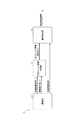
図1は、本発明の一実施形態の内部構成を示すブロック図である。この図1に示すように、動き検出装置1は、撮像部2、広Dレンジ画像生成部3、及び動き検出部4を含んで構成される。また、撮像部2は、図2に示すように、撮像レンズ5、アナログ・デジタル映像信号処理本線6及び露出制御部7を含んで構成される。
<Configuration of motion detection device>
FIG. 1 is a block diagram showing an internal configuration of an embodiment of the present invention. As shown in FIG. 1, the motion detection device 1 includes an
撮像レンズ5は、アナログ・デジタル映像信号処理本線6のイメージセンサ8(後述)の法線方向に光軸方向が向けられて当該イメージセンサ8の上方に配されている。そして、撮像レンズ5は、光軸方向からの光をイメージセンサ8に集光する。
また、アナログ・デジタル映像信号処理本線6は、イメージセンサ8、PGA(Programmable Gain Amplifier)9、及びADC(Analog-to-Digital Converter)10を含んで構成される。
The imaging lens 5 is disposed above the image sensor 8 with the optical axis direction directed in the normal direction of an image sensor 8 (described later) of the analog / digital video signal processing main line 6. The imaging lens 5 collects light from the optical axis direction on the image sensor 8.
The analog / digital video signal processing main line 6 includes an image sensor 8, a PGA (Programmable Gain Amplifier) 9, and an ADC (Analog-to-Digital Converter) 10.
イメージセンサ8は、撮像レンズ5で集光された光を電力に変換する。また、イメージセンサ8は、露出制御部7(シャッタ速度・ゲイン設定部13(後述))から出力されるシャッタ速度設定指令(後述)に対応するシャッタ速度(露光時間)が経過するたびに、その露光時間に変換された電力をPGA9に出力する電子シャッタ機能を備えている。
また、PGA9は、露出制御部7(シャッタ速度・ゲイン設定部13)から出力されるゲイン設定指令(後述)に対応するゲイン(増幅率)でイメージセンサ8から出力される電力を増幅する。そして、PGA9は、その増幅された電力をADC10に出力する。
The image sensor 8 converts the light collected by the imaging lens 5 into electric power. Further, the image sensor 8 receives the shutter speed (exposure time) corresponding to the shutter speed setting command (described later) output from the exposure control unit 7 (shutter speed / gain setting unit 13 (described later)). An electronic shutter function for outputting the power converted into the exposure time to the PGA 9 is provided.
The PGA 9 amplifies the power output from the image sensor 8 with a gain (amplification factor) corresponding to a gain setting command (described later) output from the exposure control unit 7 (shutter speed / gain setting unit 13). Then, the PGA 9 outputs the amplified power to the
さらに、ADC10は、PGA9から出力される電力をデジタル化して本線映像信号(各画素の輝度値を示す情報を含む画像データ)を生成する。そして、ADC9は、その生成された本線映像信号を露出制御部7(輝度測光部11(後述)、露出誤差検出器12(後述))と広Dレンジ画像生成部3とに出力する。
また、露出制御部7は、輝度測光部11、露出誤差検出器12及びシャッタ速度・ゲイン設定部13を含んで構成される。
Further, the
The exposure control unit 7 includes a
輝度測光部11は、アナログ・デジタル映像信号処理本線6のADC10から出力される本線映像信号が示す1画面分(1フレーム分、1フィールド分)の画像に含まれる各画素の輝度値を積分し、その積分結果を輝度評価値として露出誤差検出器12に出力する。
なお、本実施形態では、1画面分の画像に含まれる各画素の輝度値を単に積分することで輝度評価値を生成する例を示したが、これに限られるものではない。例えば、中央付近に被写体が撮像されていると想定し、中央付近の画素を重み付けして積分してもよく、また、画像を複数の領域に分割し、各領域毎に重み付けして積分するようにしてもよい。
The
In the present embodiment, the luminance evaluation value is generated by simply integrating the luminance value of each pixel included in the image for one screen. However, the present invention is not limited to this. For example, assuming that the subject is imaged near the center, the pixels near the center may be integrated by weighting, or the image may be divided into a plurality of regions and integrated by weighting each region. It may be.
また、露出誤差検出器12は、輝度測光部11から出力される輝度評価値と、外部のマイクロコントローラ(不図示)で設定される明るさの基準値(露出目標値)とを比較する。すなわち、露出誤差検出器12は、輝度評価値と露出目標値との大小関係を判定し、その判定結果をシャッタ速度・ゲイン設定部13に出力する。
さらに、シャッタ速度・ゲイン設定部13は、露出誤差検出器12から出力される判定結果が、輝度評価値が露出目標値よりも大きいことを示す場合には、シャッタ速度(露光時間)をそれまでよりも短く設定したりゲインを小さく設定したりする指令(以下、「シャッタ速度設定指令」「ゲイン設定指令」とも呼ぶ。)をアナログ・デジタル映像信号処理本線6(イメージセンサ8、PGA9)に出力する。また、シャッタ速度・ゲイン設定部13は、露出誤差検出器12から出力される判定結果が、輝度評価値が露出目標値よりも小さいことを示す場合には、シャッタ速度をそれまでよりも長く設定したりゲインを大きく設定したりする指令をアナログ・デジタル映像信号処理本線6に出力する。なお、その際、シャッタ速度Tは、イメージセンサ8の構造で決まる最短露光時間Tminの整数N倍に設定され、また、ゲインMは整数値で設定される。
The
Further, when the determination result output from the
なお、本実施形態では、シャッタ速度やゲインをフレーム単位で切り替えて設定する例を示したが、これに限られるものではない。例えば、画像を形成する複数の画素からなる画素領域単位や、画素列単位、画素単位で切り替えて設定するようにしてもよい。
また、シャッタ速度・ゲイン設定部13は、アナログ・デジタル映像信号処理本線6に出力しているシャッタ速度設定指令やゲイン設定指令が示すシャッタ速度TやゲインMに基づき、下記(1)式に従って、撮像条件値Vを生成する。そして、シャッタ速度・ゲイン設定部13は、その生成された撮像条件値を広Dレンジ画像生成部3に出力する。
In the present embodiment, the example in which the shutter speed and the gain are switched and set in units of frames has been described. However, the present invention is not limited to this. For example, it may be set by switching in units of a pixel area composed of a plurality of pixels forming an image, in units of pixel columns, or in units of pixels.
The shutter speed /
V=(Tmax×Mmax)/(T×M)
=((Tmin×Nmax)×Mmax)/((Tmin×N)×M)
=(Nmax×Mmax)/(N×M) ………(1)
V = (Tmax × Mmax) / (T × M)
= ((Tmin × Nmax) × Mmax) / ((Tmin × N) × M)
= (Nmax × Mmax) / (N × M) (1)
但し、Tmaxはイメージセンサ8が許容する最長露光時間、MmaxはPGA9が許容する最大ゲイン、Nmax(=Tmax/Tmin)は整数
なお、本実施形態では、撮像条件値Vをフレーム単位で切り替えて設定する例を示したが、これに限られるものではない。例えば、画像を形成する複数の画素からなる画素領域単位や、画素列単位、画素単位で切り替えて設定するようにしてもよい。
However, Tmax is the longest exposure time allowed by the image sensor 8, Mmax is the maximum gain allowed by the PGA 9, and Nmax (= Tmax / Tmin) is an integer. In the present embodiment, the imaging condition value V is set by switching on a frame basis. However, the present invention is not limited to this example. For example, it may be set by switching in units of a pixel area composed of a plurality of pixels forming an image, in units of pixel columns, or in units of pixels.
また、広Dレンジ画像生成部3は、図1に示すように、撮像部2(アナログ・デジタル映像信号処理本線6のADC10)から順次出力される本線映像信号I(それぞれが1画面分の画像の各画素に対応する信号)に、撮像部2(露出制御部7のシャッタ速度・ゲイン設定部13)から出力される撮像条件値Vを順次乗算して広Dレンジ画像信号WIを生成する。そして、広Dレンジ画像生成部3は、その生成された広Dレンジ画像信号WIを動き検出部4(メモリアービタ15(後述)、差分部17(後述))に順次出力する。
Further, as shown in FIG. 1, the wide D range
さらに、動き検出部4は、図3に示すように、画素カウンタ・制御部14、メモリアービタ15、画像メモリ16、差分部17及び判定部18を含んで構成される。
画素カウンタ・制御部14は、撮像部2における各種同期信号(水平同期信号、垂直同期信号、画素同期信号等)を検出し、その検出された同期信号に基づいて、広Dレンジ画像生成部3から出力されている広Dレンジ画像信号WIが示す画素のXY座標位置を算出する。また、画素カウンタ・制御部14は、広Dレンジ画像信号WIが順次入力され、XY座標位置が変わる度に、所定の制御信号をメモリアービタ15に出力し、また、前記XY座標位置に対応する画素の輝度値を記録させるアドレスを示すアドレス・制御信号を画像メモリ16に出力する。
Further, as shown in FIG. 3, the motion detection unit 4 includes a pixel counter /
The pixel counter /
また、メモリアービタ15は、画素カウンタ・制御部14から制御信号が出力されると、広Dレンジ画像生成部3から出力されている広Dレンジ信号WIが示す画素のXY座標位置に対応するアドレスから前フレームの情報(対応画素の輝度値の情報)を読み出す。そして、メモリアービタ15は、その読み出された情報を差分部17に出力すると共に、前記広Dレンジ画像信号WIが示す輝度値の情報を前記対応するアドレスに書き込む。
Further, when a control signal is output from the pixel counter /
さらに、画像メモリ16は、メモリアービタ15から読み出し要求があると、画素カウンタ・制御部14から出力されるアドレス・制御信号が示すアドレスから前フレームの情報(対応画素の輝度値の情報)をメモリアービタ15に読み出させる。また、メモリアービタ15から書き込み要求があると、画素カウンタ・制御部14から出力されるアドレス・制御信号が示すアドレスに前記書き込み要求に対応する輝度値の情報を書き込ませる。
Further, when there is a read request from the
また、差分部17は、メモリアービタ15から出力される情報が示す輝度値と、広Dレンジ画像生成部3から出力されている広Dレンジ画像信号が示す画素の輝度値との差を算出する。そして、差分部14は、その算出結果を判定部18に出力する。
さらに、判定部18は、差分部17から出力される算出結果の大きさに基づいて被写体の動きを検出し、その検出結果を、CPUや動き検出メモリ(不図示)に転送する。
The
Further, the
<動き検出装置の具体的動作>
次に、本発明に係る動き検出装置の動作を具体的状況に基づいて説明する。なお、本例は、フレーム単位で撮像条件を更新する。
<Specific operation of motion detection device>
Next, the operation of the motion detection apparatus according to the present invention will be described based on a specific situation. In this example, the imaging condition is updated in units of frames.
いま、動きの無い状態で撮像動作が行われ、このときの撮像条件値をV1とする。この撮像条件値V1により広Dレンジ画像信号が生成される(後述)。
そして、被写体の動き検出の実行中に、被写体の動きによって本線映像信号が示す現フレームの画像において一部の画素の輝度値が増大したとする。すると、図2に示すように、輝度測光部11によって、輝度評価値が露出目標値より十分に大きく算出され、露出誤差検出器12によって、その旨を示す判定結果がシャッタ速度・ゲイン設定部13に出力される。そして、シャッタ速度・ゲイン設定部13によって、シャッタ速度設定指令がアナログ・デジタル映像信号処理本線6のイメージセンサ8に出力され、ゲイン設定指令がPGA9に出力され、さらに、撮像条件値V2が広Dレンジ画像生成部3に出力される。上記動作は、現フレームの撮像動作終了後、直ちに実行され、次フレームにおいては、新しい撮像条件にて撮像動作が行われる。
Now, an imaging operation is performed without any movement, and the imaging condition value at this time is set to V1. A wide D range image signal is generated by the imaging condition value V1 (described later).
Then, it is assumed that the luminance value of some pixels in the current frame image indicated by the main line video signal is increased by the movement of the subject during the execution of the subject motion detection. Then, as shown in FIG. 2, the
そして、次フレームの検出が開始されると、イメージセンサ8によって、前記シャッタ速度設定指令に対応するシャッタ速度(露光時間)で、撮像レンズ5で集光された光が電力に変換され、その変換された電力がPGA9に出力される。また、PGA9によって、前記ゲイン設定指令に対応するゲイン(増幅率)でイメージセンサ8から出力される電力が増幅され、その増幅された電力がADC10に出力される。そして、ADC10によって、その出力された電力がデジタル化されて本線映像信号が生成され、その本線映像信号が広Dレンジ画像生成部3と輝度測光部11と露出誤差検出器12とに出力される。
When the detection of the next frame is started, the image sensor 8 converts the light collected by the imaging lens 5 into electric power at the shutter speed (exposure time) corresponding to the shutter speed setting command, and the conversion. The generated power is output to the PGA 9. The PGA 9 amplifies the power output from the image sensor 8 with a gain (amplification factor) corresponding to the gain setting command, and outputs the amplified power to the
すると、図1に示すように、広Dレンジ画像生成部3によって、その出力された本線映像信号Iに、撮像部2の露出制御部7のシャッタ速度・ゲイン設定部13から出力された撮像条件値V2が順次乗算されて広Dレンジ画像信号WIが生成される。つまり、前記本線映像信号Iを生成するときに用いられたシャッタ速度TやゲインMで当該本線映像信号Iが正規化され、背景画像の輝度値が全てのフレームで一定に保たれた広Dレンジ画像信号WIが生成される。そして、広Dレンジ画像生成部3によって、その生成された広Dレンジ画像信号WIが動き検出部4のメモリアービタ15や差分部17に順次出力される。
Then, as shown in FIG. 1, the imaging conditions output from the shutter speed /
また同時に、図3に示すように、画素カウンタ・制御部14によって、撮像部2における各種同期信号(水平同期信号、垂直同期信号、画素同期信号等)が検出され、その検出された同期信号に基づいて、広Dレンジ画像生成部3から出力されている広Dレンジ画像信号WIが示す画素のXY座標位置が検出される。そして、画素カウンタ・制御部14によって、その検出されたXY座標位置が変わるたびに、制御信号がメモリアービタ15に出力され、また、アドレス・制御信号が画像メモリ16に出力される。さらに、メモリアービタ15は、前記制御信号が出力されるたびに、広Dレンジ画像信号WIが示す画素のXY座標に対応するアドレスから前フレームの情報(対応画素の輝度値)が読み出される。そして、メモリアービタ15によって、その読み出された情報が差分部17に出力されると共に、前記広Dレンジ画像信号WIが示す輝度値の情報が前記対応するアドレスに記憶される。また、差分部17によって、その出力された情報が示す輝度値と前記広Dレンジ画像信号WIが示す画素の輝度値との差が、被写体が動いている部分で大きく算出され、また、背景部分でほぼ「0」と算出され、その算出結果が判定部18に出力される。そして、判定部18によって、その出力された算出結果の大きさに基づいて被写体の動きのある領域のみが適切に検出され、その検出結果がCPUや動き検出メモリ(不図示)に転送される。
At the same time, as shown in FIG. 3, the pixel counter /
このように、本実施形態の動き検出装置によれば、露出制御動作が働いて電子シャッタのシャッタ速度やゲインが変化した場合、シャッタ速度やゲインで画像の輝度値を正規化することで、背景画像の輝度値を一定に保つことができる。そのため、背景画像にフレーム差分が生じることを防止することができ、例えば、撮像部2で撮像された画像をそのまま用いて被写体の動きを検出する方法に比べ、動き検出の精度を向上することができる。
As described above, according to the motion detection device of the present embodiment, when the shutter speed and the gain of the electronic shutter change due to the exposure control operation, the luminance value of the image is normalized by the shutter speed and the gain. The brightness value of the image can be kept constant. Therefore, it is possible to prevent a frame difference from occurring in the background image. For example, it is possible to improve the accuracy of motion detection compared to a method of detecting the motion of the subject using the image captured by the
以上、図1の広Dレンジ画像生成部3が特許請求の範囲に記載の正規化手段を構成し、同様に、図1の動き検出部4、図3の差分部17が検出手段を構成する。
なお、図1の広Dレンジ画像生成部3が特許請求の範囲に記載の正規化手段を構成する。また、本発明の動き検出装置は、上記実施の形態の内容に限定されるものではなく、本発明の趣旨を逸脱しない範囲で適宜変更可能である。
As described above, the wide D range
The wide D range
1は検出装置、2は撮像部、3はレンジ画像生成部、4は検出部、5は撮像レンズ、6はアナログ・デジタル映像信号処理本線、7は露出制御部、8はイメージセンサ、9はPGA、10はADC、11は輝度測光部、12は露出誤差検出器、13はシャッタ速度・ゲイン設定部、14は画素カウンタ・制御部、15はメモリアービタ、16は画像メモリ、17は差分部、18は判定部 1 is a detection device, 2 is an imaging unit, 3 is a range image generation unit, 4 is a detection unit, 5 is an imaging lens, 6 is an analog / digital video signal processing main line, 7 is an exposure control unit, 8 is an image sensor, and 9 is PGA, 10 ADC, 11 brightness metering unit, 12 exposure error detector, 13 shutter speed / gain setting unit, 14 pixel counter / control unit, 15 memory arbiter, 16 image memory, 17 difference unit , 18 is a determination unit
Claims (10)
前記第2の時刻における電子シャッタのシャッタ速度と前記第2の画像を撮像したイメージセンサの出力に乗じたゲインとの少なくとも一方を用いて前記第2の画像の輝度値を正規化する正規化手段と、前記第1の画像と前記正規化手段で輝度値が正規化された前記第2の画像とに基づいて前記輝度値が変化した領域を検出する検出手段とを有することを特徴とする動き検出装置。 A motion detection device that detects a motion of a subject based on a first image captured at a first time and a second image captured at a second time different from the first time,
Normalizing means for normalizing the brightness value of the second image using at least one of the shutter speed of the electronic shutter at the second time and the gain multiplied by the output of the image sensor that captured the second image. And a detecting means for detecting a region in which the brightness value has changed based on the first image and the second image whose brightness value has been normalized by the normalizing means. Detection device.
前記検出手段では、前記正規化手段で輝度値が正規化された前記第1及び第2の画像とに基づいて前記輝度値が変化した領域を検出することを特徴とする請求項1又は2に記載の動き検出装置。 In the normalizing means, the luminance value of the first image is calculated using at least one of a shutter speed of the electronic shutter at the first time and a gain multiplied by an output of an image sensor that has captured the first image. Normalize,
The detection unit detects an area where the luminance value has changed based on the first and second images whose luminance values are normalized by the normalizing unit. The motion detection device described.
前記第2の時刻における電子シャッタのシャッタ速度と前記第2の画像を撮像したイメージセンサの出力に乗じたゲインとの少なくとも一方を用いて前記第2の画像の輝度値を正規化する正規化手段と、
前記第1の画像を構成する画素の輝度値と前記正規化手段で輝度値が正規化された前記第2の画像を構成する画素の輝度値とを記憶する記憶手段と、
前記第1の画像を構成する所定の画素の輝度値と、前記所定の画素の位置に対応する位置の前記正規化手段で輝度値が正規化された前記第2の画像を構成する画素の輝度値と、の差分を算出する差分手段と、
前記差分手段によって算出された差分の大きさに基づいて、前記輝度値が変化した領域を検出する判定手段と、
を有することを特徴とする動き検出装置。 A motion detection device that detects a motion of a subject based on a first image captured at a first time and a second image captured at a second time different from the first time,
Normalizing means for normalizing the brightness value of the second image using at least one of the shutter speed of the electronic shutter at the second time and the gain multiplied by the output of the image sensor that captured the second image. When,
Storage means for storing a luminance value of a pixel constituting the first image and a luminance value of a pixel constituting the second image whose luminance value is normalized by the normalizing means;
The luminance value of a predetermined pixel constituting the first image and the luminance value of the pixel constituting the second image whose luminance value is normalized by the normalizing means at a position corresponding to the position of the predetermined pixel A difference means for calculating a difference between the value and
Determination means for detecting an area where the luminance value has changed based on the magnitude of the difference calculated by the difference means;
A motion detection apparatus comprising:
前記撮像部の撮像条件を制御する露出制御部と、
前記第1の画像と前記第2の画像とに基づき動きを検出する動き検出部と、を備え、
前記露出制御部が輝度測光部と露出誤差検出器とシャッタ速度・ゲイン設定部とを含み、
前記撮像部が前記第1の画像に対応する映像信号を出力し、前記輝度測光部が前記映像信号に基づく複数の画素の輝度値を積分し輝度評価値として前記露出誤差検出器へ出力し、前記露出誤差検出器が前記輝度評価値と露出目標値との大小関係を判定して判定結果を前記シャッタ速度・ゲイン設定部へ出力するものであり、
前記輝度評価値が前記露出目標値よりも大きい場合、前記シャッタ速度・ゲイン設定部が前記シャッタ速度を前記判定結果の出力された時点よりも短く設定する指令または前記ゲインを前記判定結果の出力された時点よりも小さく設定する指令を、前記撮像部へ出力し、前記撮像部が前記指令に基づき前記第2の画像を撮像するものであり、
前記輝度評価値が前記露出目標値よりも小さい場合、前記シャッタ速度・ゲイン設定部が前記シャッタ速度を前記判定結果の出力された時点よりも長く設定する指令または前記ゲインを前記判定結果の出力された時点よりも大きく設定する指令を、前記撮像部へ出力し、前記撮像部が前記指令に基づき前記第2の画像を撮像するものである、ことを特徴とする動き検出装置。 An imaging unit that captures a first image at a first time and captures a second image at a second time;
An exposure control unit that controls imaging conditions of the imaging unit;
A motion detector that detects motion based on the first image and the second image;
The exposure control unit includes a luminance metering unit, an exposure error detector, and a shutter speed / gain setting unit,
The imaging unit outputs a video signal corresponding to the first image, and the luminance photometry unit integrates luminance values of a plurality of pixels based on the video signal and outputs the luminance evaluation values to the exposure error detector, The exposure error detector determines a magnitude relationship between the brightness evaluation value and an exposure target value and outputs a determination result to the shutter speed / gain setting unit ;
When the brightness evaluation value is larger than the exposure target value, the shutter speed / gain setting unit outputs a command for setting the shutter speed to be shorter than the time when the determination result is output or the gain is output as the determination result. A command to set smaller than the time point is output to the imaging unit, and the imaging unit captures the second image based on the command,
When the luminance evaluation value is smaller than the exposure target value, the shutter speed / gain setting unit outputs a command for setting the shutter speed longer than the time when the determination result is output or the gain is output as the determination result. A motion detection device characterized in that a command to set larger than the time point is output to the imaging unit, and the imaging unit captures the second image based on the command.
前記輝度測光部が前記複数の画素のうち中央付近の画素を重み付けして積分するものである、ことを特徴とする動き検出装置。 The motion detection device according to claim 6,
The motion photometric device is characterized in that the luminance metering unit weights and integrates a pixel near the center among the plurality of pixels.
前記複数の画素が複数の領域に分割され、前記輝度測光部が前記複数の画素を前記複数の領域毎に重み付けして積分するものである、ことを特徴とする動き検出装置。 The motion detection device according to claim 6,
The motion detection device, wherein the plurality of pixels are divided into a plurality of regions, and the luminance photometry unit weights and integrates the plurality of pixels for each of the plurality of regions.
前記第1の画像と前記第2の画像とで互いに異なる部分の検出に用いられる画像の輝度値を補正するものである、ことを特徴とする動き検出装置。 The motion detection device according to claim 1,
A motion detection apparatus for correcting a luminance value of an image used for detecting different portions of the first image and the second image.
前記第1の画像と前記第2の画像とで互いに共通する背景画像の輝度値を一定に保つものである、ことを特徴とする動き検出装置。 The motion detection device according to claim 1,
A motion detection apparatus, characterized in that a luminance value of a background image common to the first image and the second image is kept constant.
Priority Applications (1)
| Application Number | Priority Date | Filing Date | Title |
|---|---|---|---|
| JP2004324749A JP4329677B2 (en) | 2004-11-09 | 2004-11-09 | Motion detection device |
Applications Claiming Priority (1)
| Application Number | Priority Date | Filing Date | Title |
|---|---|---|---|
| JP2004324749A JP4329677B2 (en) | 2004-11-09 | 2004-11-09 | Motion detection device |
Related Child Applications (1)
| Application Number | Title | Priority Date | Filing Date |
|---|---|---|---|
| JP2007294006A Division JP4285573B2 (en) | 2007-11-13 | 2007-11-13 | Motion detection device |
Publications (3)
| Publication Number | Publication Date |
|---|---|
| JP2006135838A JP2006135838A (en) | 2006-05-25 |
| JP2006135838A5 JP2006135838A5 (en) | 2007-12-20 |
| JP4329677B2 true JP4329677B2 (en) | 2009-09-09 |
Family
ID=36728933
Family Applications (1)
| Application Number | Title | Priority Date | Filing Date |
|---|---|---|---|
| JP2004324749A Expired - Fee Related JP4329677B2 (en) | 2004-11-09 | 2004-11-09 | Motion detection device |
Country Status (1)
| Country | Link |
|---|---|
| JP (1) | JP4329677B2 (en) |
Families Citing this family (5)
| Publication number | Priority date | Publication date | Assignee | Title |
|---|---|---|---|---|
| JP4626689B2 (en) | 2008-08-26 | 2011-02-09 | ソニー株式会社 | Imaging apparatus, correction circuit, and correction method |
| JP4678061B2 (en) * | 2009-04-02 | 2011-04-27 | 株式会社ニコン | Image processing apparatus, digital camera equipped with the same, and image processing program |
| JP6319709B2 (en) * | 2014-03-21 | 2018-05-09 | 株式会社Ihi | Debris detection method |
| WO2021070813A1 (en) * | 2019-10-08 | 2021-04-15 | 株式会社デンソー | Error estimation device, error estimation method, error estimation program |
| KR20230173667A (en) * | 2021-04-19 | 2023-12-27 | 한화비전 주식회사 | Controlling the shutter value of a surveillance camera through AI-based object recognition |
-
2004
- 2004-11-09 JP JP2004324749A patent/JP4329677B2/en not_active Expired - Fee Related
Also Published As
| Publication number | Publication date |
|---|---|
| JP2006135838A (en) | 2006-05-25 |
Similar Documents
| Publication | Publication Date | Title |
|---|---|---|
| US11431937B2 (en) | Data rate control for event-based vision sensor | |
| KR102668130B1 (en) | Generating static images with an event camera | |
| JP2006005520A (en) | Imaging apparatus | |
| JP2022076837A (en) | Information processing device, information processing method, and program | |
| US20130329091A1 (en) | Image capture device, method for generating composite image, and storage medium | |
| JP4329677B2 (en) | Motion detection device | |
| US10129449B2 (en) | Flash band, determination device for detecting flash band, method of controlling the same, storage medium, and image pickup apparatus | |
| JP2006295707A (en) | Image reproducing apparatus and image blurring correction program | |
| US10965877B2 (en) | Image generating method and electronic apparatus | |
| JP2008131572A (en) | Monitoring camera apparatus and photographing method of same | |
| JP4285573B2 (en) | Motion detection device | |
| JP2829801B2 (en) | Vehicle dynamics measurement device in tunnel | |
| JP2006311367A (en) | Imaging apparatus and imaging method | |
| JP3751799B2 (en) | Apparatus and method for correcting shake of imaging apparatus | |
| JP2014150409A (en) | Image processing device, imaging device, and image processing program | |
| JP7031570B2 (en) | Vibration detection method | |
| US10187559B2 (en) | Flash band determination device for detecting flash band, method of controlling the same, storage medium, and image pickup apparatus | |
| JP2008312169A (en) | Image processing apparatus and method, and imaging apparatus | |
| US20230247306A1 (en) | Image capturing apparatus, information processing apparatus, control method, and storage medium | |
| US10785420B2 (en) | Imaging device and camera for minimizing a digital gain value to be multiplied and suppressing noise | |
| JP2962290B2 (en) | Automatic monitoring device in tunnel | |
| JP6066942B2 (en) | Image processing device | |
| WO2020152997A1 (en) | Image processing system and camera system | |
| JP2023104719A (en) | Imaging apparatus, control method, and computer program | |
| JPH1127654A (en) | Monitoring camera and monitoring system |
Legal Events
| Date | Code | Title | Description |
|---|---|---|---|
| RD04 | Notification of resignation of power of attorney |
Free format text: JAPANESE INTERMEDIATE CODE: A7424 Effective date: 20070403 |
|
| A521 | Request for written amendment filed |
Free format text: JAPANESE INTERMEDIATE CODE: A523 Effective date: 20071107 |
|
| A621 | Written request for application examination |
Free format text: JAPANESE INTERMEDIATE CODE: A621 Effective date: 20071107 |
|
| A131 | Notification of reasons for refusal |
Free format text: JAPANESE INTERMEDIATE CODE: A131 Effective date: 20081209 |
|
| A521 | Request for written amendment filed |
Free format text: JAPANESE INTERMEDIATE CODE: A523 Effective date: 20090209 |
|
| A131 | Notification of reasons for refusal |
Free format text: JAPANESE INTERMEDIATE CODE: A131 Effective date: 20090303 |
|
| A521 | Request for written amendment filed |
Free format text: JAPANESE INTERMEDIATE CODE: A523 Effective date: 20090420 |
|
| TRDD | Decision of grant or rejection written | ||
| A01 | Written decision to grant a patent or to grant a registration (utility model) |
Free format text: JAPANESE INTERMEDIATE CODE: A01 Effective date: 20090526 |
|
| A01 | Written decision to grant a patent or to grant a registration (utility model) |
Free format text: JAPANESE INTERMEDIATE CODE: A01 |
|
| A61 | First payment of annual fees (during grant procedure) |
Free format text: JAPANESE INTERMEDIATE CODE: A61 Effective date: 20090608 |
|
| R150 | Certificate of patent or registration of utility model |
Ref document number: 4329677 Country of ref document: JP Free format text: JAPANESE INTERMEDIATE CODE: R150 Free format text: JAPANESE INTERMEDIATE CODE: R150 |
|
| FPAY | Renewal fee payment (event date is renewal date of database) |
Free format text: PAYMENT UNTIL: 20120626 Year of fee payment: 3 |
|
| FPAY | Renewal fee payment (event date is renewal date of database) |
Free format text: PAYMENT UNTIL: 20130626 Year of fee payment: 4 |
|
| FPAY | Renewal fee payment (event date is renewal date of database) |
Free format text: PAYMENT UNTIL: 20130626 Year of fee payment: 4 |
|
| S531 | Written request for registration of change of domicile |
Free format text: JAPANESE INTERMEDIATE CODE: R313531 |
|
| R350 | Written notification of registration of transfer |
Free format text: JAPANESE INTERMEDIATE CODE: R350 |
|
| LAPS | Cancellation because of no payment of annual fees |