JP4329101B2 - Multipurpose container - Google Patents
Multipurpose container Download PDFInfo
- Publication number
- JP4329101B2 JP4329101B2 JP2004290995A JP2004290995A JP4329101B2 JP 4329101 B2 JP4329101 B2 JP 4329101B2 JP 2004290995 A JP2004290995 A JP 2004290995A JP 2004290995 A JP2004290995 A JP 2004290995A JP 4329101 B2 JP4329101 B2 JP 4329101B2
- Authority
- JP
- Japan
- Prior art keywords
- container
- lid
- fitted
- main body
- fitting
- Prior art date
- Legal status (The legal status is an assumption and is not a legal conclusion. Google has not performed a legal analysis and makes no representation as to the accuracy of the status listed.)
- Expired - Fee Related
Links
Images


Landscapes
- Instructional Devices (AREA)
- Package Specialized In Special Use (AREA)
- Cartons (AREA)
- Details Of Rigid Or Semi-Rigid Containers (AREA)
Description
本発明は、容器本体と、この容器本体の開口上端部に嵌合して閉蓋する蓋とを備えた容器において、各種の物品を収容する用途に加え、他の用途を付与した多用途容器に関する。 The present invention provides a container having a container body and a lid that fits and closes the upper end of the opening of the container body. About.
従来、容器本体と、この容器本体の開口上端部に嵌合する蓋とからなり、蓋を嵌合した際に、蓋と容器本体の外面が平ら(面一)になるように構成した容器として種々の形状や型式のものが一般に知られている。
従来のこの種容器(印籠式と称されている)は、一般には販売する各種商品を収容して包装する包装用容器として使用されている。これらの包装用容器は、目的の商品を包装する包装用として製造されたもので、商品を購入した後、前記容器はほとんどの場合廃棄処分されている。そのため、資源の無駄使いになると共にゴミ公害の要因にもなっている。
Conventionally, as a container composed of a container main body and a lid fitted to the upper end of the opening of the container main body so that the outer surface of the lid and the container main body is flat when the lid is fitted. Various shapes and types are generally known.
Conventionally, this kind of container (referred to as a seal type) is generally used as a packaging container for accommodating and packaging various products to be sold. These packaging containers are manufactured for packaging the intended product, and after purchasing the product, the container is almost always disposed of. For this reason, it is a waste of resources and a factor of garbage pollution.
ところで、地球儀は地球をかたどった小模型である。従来の地球儀は球体の表面に世界地図を描き、前記球体を、北極及び南極を通る軸を中心に回転自在、かつ、前記軸に所定の傾斜角度を持たせて支持させて構成されている。
地球儀は地球や世界地理等の知識を得るために重要であり、購入当初は机上等に置いて利用している。しかるに、地球儀は球体の回転支持機構等を備えているため、設置スペースが大になる。また、従来の地球儀は専ら地球儀としての用途しか備えていない。そのため、押入れや物置等に仕舞い込んで置かれることが多く見受けられる。
By the way, the globe is a small model shaped like the earth. A conventional globe is constructed by drawing a world map on the surface of a sphere, and supporting the sphere with an axis passing through the North Pole and the South Pole with a predetermined inclination angle.
The globe is important for obtaining knowledge about the earth and world geography, and is initially placed on a desk or the like when purchased. However, since the globe has a spherical rotation support mechanism and the like, the installation space becomes large. Moreover, the conventional globe has only the use as a globe. For this reason, it is often found that they are placed in a closet or a storeroom.
本発明は上記のような実情に鑑み、各種商品の物入れ用として使用できるとともに地球儀としても利用でき、もって容器の付加価値を向上させ、かつ、ゴミ公害の問題の解消にも貢献し得る多用途容器を提供することを目的とするものである。 In view of the above circumstances, the present invention can be used as a container for various goods and can also be used as a globe, thereby improving the added value of the container and contributing to the elimination of the problem of dust pollution. The purpose is to provide a container.
前記目的を達成するため、本発明のうち1つの発明(第1の発明)は、容器本体と、この容器本体の開口上端部に嵌合して閉蓋する蓋とを有し、蓋を容器本体に嵌合した際に、蓋の外面と容器本体の外面が面一になるように構成した容器を備え、前記容器本体は、容器本体の上端部側に形成され、前記蓋を嵌合する嵌合用筒状部を備え、前記筒状部に前記蓋を嵌合した際に、容器の中央部外周面を周回する隙間を形成して閉蓋するように構成され、前記容器の外面には、前記隙間により形成される周回線を赤道とする世界地図が表示されていることを特徴とする。本発明の用途は特に限定するものではない。例えば、筆記用具などの筆入れ用やその他の物入れ用、或いは包装用等、広範囲に適応可能である。 In order to achieve the above object, one of the present inventions (first invention) includes a container body and a lid that fits and closes the upper end of the opening of the container body, and the lid is a container. A container configured so that the outer surface of the lid and the outer surface of the container main body are flush with each other when fitted to the main body, and the container main body is formed on the upper end side of the container main body, and engages with the lid A fitting cylindrical part is provided, and when the lid is fitted to the cylindrical part, the gap is formed around the outer peripheral surface of the central part of the container so as to be closed, and the outer surface of the container is A world map is displayed with the equator being the circumferential line formed by the gap. The application of the present invention is not particularly limited. For example, the present invention can be applied in a wide range such as for writing cases such as writing utensils, for other things, or for packaging.
本発明のうち、他の1つの発明(第2の発明)は、容器本体と、この容器本体の開口上端部に嵌合して閉蓋する蓋とを有し、蓋を容器本体に嵌合した際に、蓋の外面と容器本体の外面が面一になるように構成した容器を備え、前記容器本体は、容器本体の上端部側に形成され、前記蓋を嵌合する嵌合用筒状部と、この筒状部の下端部に設けられ、前記筒状部の外周面を周回させて取付けた化粧紐状体とを有し、前記筒状部に前記蓋を嵌合した際に、前記蓋の下端を前記紐状体に当接して閉蓋し、容器の中央部外周面に前記紐状体で周回線を形成するように構成され、前記容器の外面には、前記紐状体により形成される前記周回線を赤道とする世界地図が表示されていることを特徴とする。 Among the present inventions, another one of the inventions (second invention) has a container body and a lid that fits and closes the upper open end of the container body, and the lid is fitted to the container body. A container that is configured so that the outer surface of the lid and the outer surface of the container body are flush with each other, and the container body is formed on the upper end side of the container body and fits the lid And a decorative string-like body that is provided at the lower end portion of the cylindrical portion and attached around the outer peripheral surface of the cylindrical portion, and when the lid is fitted to the cylindrical portion, The lower end of the lid is in contact with the string-like body to close the lid, and a circumferential line is formed on the outer peripheral surface of the central portion of the container with the string-like body. The string-like body is formed on the outer surface of the container. A world map having the equator as the circumference line formed by is displayed.
第1又は第2の発明の多用途容器において、前記容器は四角形に形成されている。 In the multipurpose container of the first or second invention, the container is formed in a quadrangular shape.
本発明のうち他の1つの発明(第3の発明)は、第1又は第2の発明の多用途容器において、前記容器本体は、外側容器と、この外側容器内に底部側を嵌合した内側容器とを有し、前記嵌合用筒状部は、前記内側容器の上端部側で形成されていることを特徴とする。 Another invention of the present invention ( third invention) is the versatile container of the first or second invention, wherein the container body is fitted with an outer container and a bottom side in the outer container. An inner container, and the fitting cylindrical part is formed on an upper end side of the inner container.
本発明のさらに他の1つの発明(第4の発明)は、第1又は第2の発明の多用途容器において、前記容器本体は、容器本体の上端部側に、前記蓋の嵌合部の厚みと対応し、かつ、前記容器本体の外周面を周回する段部を介して一体形成した延設筒状部を有し、前記嵌合用筒状部は前記延設筒状部で構成されていることを特徴とする。 Still another invention of the present invention ( fourth invention) is the versatile container of the first or second invention, wherein the container body is provided on the upper end side of the container body with the fitting portion of the lid. An extending cylindrical portion corresponding to the thickness and integrally formed through a stepped portion that circulates around the outer peripheral surface of the container body, and the fitting cylindrical portion is configured by the extending cylindrical portion. It is characterized by being.
本発明によれば次のような効果を奏する。(1)例えば、容器を筆記用具入れ、小物入れ、その他の各種物品の物入れ用に作成した場合、物入れ機能に加え、容器を地球儀として利用することができる。(2)例えば、旅行会社で使用するように作成した場合にあっては、ツーリスト関係の案内小冊子等をいれてツアーに参加する者に配布する容器として好適であり、当該ツーリストは容器を地球儀として利用することができる。また、旅行を終了して帰宅した後においては、容器を物入れとして使用することができる。(3)包装用容器用として作成した場合にあっては、販売する各種商品の包装用として使用できる。また、容器には世界地図が描かれているので、商品の購入者は、従来のように容器を廃棄しないで、所望の物品の物入れ用容器として使用されると共に地球儀として利用されることになる。(4)容器の中央部外周面を周回する周回線を赤道とし、容器を地球に見たてて世界地図を描いてあるので、従来の地球儀とは感覚的に全く異質で興味を与える地球儀を提供できる。(5)容器の中央部外周面を周回する隙間を形成して閉蓋するように構成し、前記隙間により形成される周回線を赤道として世界地図を表示してあるので、北半球の地図と南半球の地図との境界線に多少のズレが生じていても不自然を感じることなく合致しているように見えると共に前記隙間を赤道に見たててあるので地図が見易くなる。(6)従来の球形の地球儀と比べて設置スペースを小さくすることができる。 The present invention has the following effects. (1) For example, when a container is made for a writing instrument case, an accessory case, or other various articles, the container can be used as a globe in addition to the case function. (2) For example, when it is created for use by a travel agency, it is suitable as a container for distributing tourist-related guide booklets etc. to those who participate in the tour, and the tourist uses the container as a globe. Can be used. In addition, the container can be used as a container after returning from the trip. (3) When prepared for packaging containers, it can be used for packaging various products to be sold. In addition, since the world map is drawn on the container, the purchaser of the product will not only discard the container as in the conventional case, but will be used as a container for storing desired articles and as a globe. . (4) Since the circuit around the center outer circumference of the container is the equator and the container is seen on the earth, a world map is drawn. Can be provided. (5) It is configured to form a gap around the outer peripheral surface of the central portion of the container and close the lid, and since the world map is displayed with the circumference line formed by the gap as the equator, the map of the Northern Hemisphere and the Southern Hemisphere Even if there is a slight deviation in the boundary line between the map and the map, it seems to match without feeling unnatural and the gap is seen on the equator, making it easy to see the map. (6) The installation space can be reduced as compared with a conventional spherical globe.
以下、本発明の実施の形態の一例を説明する。 Hereinafter, an example of an embodiment of the present invention will be described.
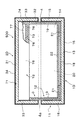
図1は本発明の多用途容器の一実施の形態を示す斜視図、図2は同上容器の底面図、図3は同図1のA−A線拡大断面図、図4は同上容器の蓋を開けた状態を示す斜視図(但し、世界地図は省略)、図5は同上容器の蓋を展開して示す説明図、図6は同上容器の容器本体の外側容器を展開して示す説明図である。 1 is a perspective view showing an embodiment of a multi-use container according to the present invention, FIG. 2 is a bottom view of the same container, FIG. 3 is an enlarged cross-sectional view taken along line AA of FIG. 1, and FIG. FIG. 5 is an explanatory view showing the lid of the same container unfolded, FIG. 6 is an explanatory view showing the outer container of the container main body unfolded. It is.
上記図1〜図6において、この実施の形態(実施の形態1)の多用途容器の容器100は、容器本体1と、この容器本体1の開口上端部に篏脱自在に嵌合して閉蓋する蓋2とを備えている。容器100の素材は特に限定するものではないが、例えば紙材、プラスチック(発泡性樹脂を含む)、或いは金属板等を挙げることができる。
また、前記容器の形状及び大きさは使用目的等に応じて任意に設定することができる。
1 to 6, the
The shape and size of the container can be arbitrarily set according to the purpose of use.
実施の形態1は、容器100の素材として紙材を採用し、長四角形断面の箱形に形成されている。容器100の大きさは前述したように使用目的等に応じて任意に設定する。例えば、筆記用具などの筆入れ用や小物入れ用に構成する場合には、容器100のサイズとして、例えば、横巾約10cm、縦巾約19cm、高さ約6cm程度に形成することができる。但し、前記サイズに限定されるものでないこと勿論である。
The first embodiment employs a paper material as a material of the
容器本体1は、上端部(図示では略上半部)に前記蓋2を嵌合する嵌合用筒状部3を備え、前記筒状部3に蓋2を嵌合した際に、蓋2の外面と容器本体1の外面が面一(平ら)になると共に、容器100の中央部外周面を周回する所望巾の隙間4を形成して閉蓋するように構成されている。
The container body 1 includes a fitting
実施の形態1の容器本体1は外側容器11と、この外側容器11内に底部側(図示では略下半部)を嵌合した内側容器12とを有し、前記嵌合用筒状部3は内側容器12の上端部(図示では略上半部)で形成されている。
The container main body 1 of Embodiment 1 has an
実施の形態1の外側容器11は、ボール紙その他の厚紙材で作られ、底壁板13と、前後及び左右に対向する一対の対向壁板14,14、15,15とを有し、上端を開口した長方形の箱形に形成され、外側面には紙製等の表装材16を接着その他の手段で貼り合わせて構成されている。実施の形態1では前記表装材16の上端部を折り返して外側容器11の内側面に重合し、貼り合わせてなるものが開示されている。そして、前記表装材16には世界地図17の南半球の地図17aが印刷その他の手段で表示されている。この地図17の構成等については追って説明する。
前記外側容器11は前記蓋2と合致する形状及びサイズに形成されている。
The
The
前記内側容器12は、紙材等を折り曲げて底壁板18と、前後及び左右に対向する一対の対向壁板19,19、20,20とを有し、上端を開口した長方形の折り箱で構成されている。内側容器12の略下半部は外側容器11内に嵌合され、内側容器12の外側容器11から突出した略上半部で蓋2を嵌合する嵌合用筒状部3が形成されている。
実施の形態1の内側容器12は、各対向壁板19,20の各下端部をそれぞれ内側へ折り曲げた折り曲げ片21を有し、折り曲げ片21の上面に底敷板22を敷設してある。この場合、上記折り曲げ片21及び底敷板22は省略してもよい。また、前記内側容器12は外側容器11の適当部に接着剤等で接着して嵌合するように構成することもできる。
The
The
前記内側容器12の高さは、蓋2を前記筒状部3に嵌合した際に、容器100の中央部外周面に前記隙間4を形成して閉蓋する高さに構成されている。即ち、蓋2を前記筒状部3に嵌合し、前記筒状部3の上端が蓋2の天板31の下面に当接した状態で前記隙間4が形成される高さに設定されている。
前記隙間4の巾のサイズは適当に設定するものであるが、例えば約1.5ミリ〜約5ミリ程度に設定することができる。
The height of the
The width of the
前記蓋2は上述したように外側容器11と同一形状及び同一サイズに形成されている。実施の形態1の蓋2は、ボール紙その他の厚紙材で天板31と、前後及び左右に対向する一対の対向壁板32,32、33,33とを有し、下端を開口した長方形の箱形に形成され、外側面には紙製等の表装材34を接着その他の手段で貼り合わせて構成されている。実施の形態1では前記表装材34の下端部を折り返して蓋2の内側面に重合し、貼り合わせてなるものが開示されている。
この場合において、所望に応じ、蓋2の内側面の全面に紙製等の裏貼り材(図示せず)を張り合わせた構成を採用することもできる。そして、前記表装材34には世界地図17の北半球の地図17bが印刷その他の手段で表示されている。
The
In this case, if desired, a configuration in which a backing material (not shown) made of paper or the like is bonded to the entire inner surface of the
上記構成により、蓋2を容器本体1の前記筒状部3へ嵌合して押動すると、前記筒状部3の上端に天板31の下面が当接した時点で係止され、閉蓋される。この状態において、蓋2の外面と外側容器11の外面は面一(平ら)になると共に容器100の中央部には、容器を周回する前記隙間4が形成され、前記隙間4により周回線4aが形成される。
With the above configuration, when the
前記容器100の外面、即ち、前記表装材16,34には、容器100を地球に見たて、前記隙間4により形成される周回線4aを赤道とする世界地図17が表示されている。
前記地図17は、表装材16,34に印刷等によりあらかじめ印刷されている。即ち、表装材16には南半球の地図17aが、また、表装材34には北半球の地図17bが表示されている。そして、表装材16は外側容器11に、また、表装材34は蓋2に貼り合わせてある。
A
The
前記地図17の構成は写実的、或いはデフォルメする等、自由に表現して作成することができる。前記地図17には図5及び図6に示すように、国名や主要な都市等を記載する。最小限においても国名等は記載する。経度及び緯度は記載することが好ましいが、省略してもよい。また、特定の用途、例えば、旅行会社用の容器を作成する場合には、前記地図のうち、目的地の部分を拡大したり、或いは詳細に表示し、他の地域は国名等だけを表示する等の地図構成を採用することもできる。
なお、前記内側容器12は、赤色系,オレンジ系,青色系その他任意の色に着色した紙材で構成することができる。この場合、例えば、赤色系に着色した紙材を採用すると、前記周回線4aは赤色系の線で構成されるので、前記線4aが赤道であることを感覚的に表現することができる。但し、上記したように、赤色系以外の任意の色を採用できるものである。
The structure of the
The
実施の形態1の多用途容器は上記のように構成したもので、次に使用方法の一例等につき説明する。例えば、筆記用具入れとして使用する場合(使用例1)には、従来と同様に机上等に置き、筆記用具を収容する容器として使用する。この例においては容器は卓上に置いてあるので、利用者は容器に表示されている世界地図を見る回数が多くなる。したがって、世界地図の知識を必然的に収得することになる。 The multipurpose container of Embodiment 1 is configured as described above. Next, an example of a usage method and the like will be described. For example, when used as a writing instrument case (Usage Example 1), it is placed on a desk or the like as in the prior art and used as a container for storing the writing instrument. In this example, since the container is placed on the table, the user frequently views the world map displayed on the container. Therefore, the knowledge of the world map is inevitably acquired.
また、例えば、小物入れ等として使用する場合(使用例2)には、容器の中に所望の物品を収容して従来と同様に使用する。この例においても容器は身近にあるため、物品を出し入れする毎に世界地図を見ることになる。したがって、使用例1と同様に世界地図の知識を必然的に収得する。 Further, for example, when used as an accessory case (Usage Example 2), a desired article is accommodated in a container and used in the same manner as before. In this example as well, the container is close, so every time an article is taken in or out, the world map is viewed. Therefore, the knowledge of the world map is inevitably acquired as in the first use example.
さらにまた、例えば、旅行会社用の場合(使用例3)には、当該会社はツーリスト関係の案内小冊子等を容器に入れ、ツアーに参加する者に配布する。そして、当該ツーリストは配布された容器を持参して旅行する。また、旅行を終了して帰宅した後においては、思い出として容器を小物入れ等に使用されることが多くなると思われる。したがって、これにより、使用例1,2と同様に世界地図の知識を必然的に収得する。 Furthermore, for example, in the case of a travel company (use example 3), the company places a tourist-related guide booklet or the like in a container and distributes it to those who participate in the tour. The tourist then travels with the distributed container. In addition, after returning home after traveling, it seems that containers are often used for small items as memories. Therefore, as a result, the knowledge of the world map is inevitably acquired as in the first and second usage examples.
さらにまた、例えば、包装用容器として使用する場合(使用例4)には、従来と同様に各種の商品を容器に収容して販売する。そして、商品の購入者は従来のように容器を廃棄しないで、所望の物品の物入れ用容器として使用することが多くなると思う。したがって、使用例4においても使用例1,2と同様に世界地図の知識を必然的に収得されることになる。 Furthermore, for example, when used as a packaging container (Usage Example 4), various products are housed and sold in the same manner as in the past. And the purchaser of goods thinks that it will use more as a container for container of a desired article, without discarding a container conventionally. Therefore, in the usage example 4, as in the usage examples 1 and 2, knowledge of the world map is inevitably acquired.
なお、上記使用例は一例として挙げたもので、上記以外の用途に利用できること勿論である。この点に関しては以下に説明する実施の形態においても同様である。 In addition, the said usage example was mentioned as an example, and of course, it can utilize for uses other than the above. This also applies to the embodiments described below.
また、実施の形態1では、蓋2側に北半球の地図17bを、また、容器本体1側に南半球の地図17aを表示した例が開示されているが、地図17は実施の形態1と天地逆の構成としてもよい。
即ち、前記周回線4aを赤道とし、蓋2に南半球の地図17aを、また、容器本体1に北半球の地図17bを表示する地図構成を採用することもできる。この構成を採用した場合においても実施の形態1と同様に使用するものであり、作用効果についても同様である。なお、上記した点については、以下に説明する各実施の形態においても同様である。
In the first embodiment, an example is shown in which the
That is, it is possible to adopt a map configuration in which the
図7は本発明の多用途容器の他の実施の形態(実施の形態2)を示す縦断面図である。この多用途容器において、実施形態1で既に説明した構成と共通する部材等には同一符号を付し、説明を省略する。実施の形態2は容器本体の構成に特徴がある。 FIG. 7 is a longitudinal sectional view showing another embodiment (Embodiment 2) of the multipurpose container of the present invention. In this multipurpose container, members and the like that are the same as those already described in the first embodiment are denoted by the same reference numerals, and description thereof is omitted. The second embodiment is characterized by the configuration of the container body.
実施の形態2の多用途容器の容器200は、容器本体1Aと蓋2Aをプラスチック等で構成してある。容器本体1Aは、容器本体1Aの上端部(図示では略上半部)に、蓋2Aの対向壁板32,32、33,33の厚みと対応し、かつ、容器本体1Aの外周面を周回する段部40を介して一体形成した延設筒状部41を有している。前記筒状部41は、容器本体1Aの前後及び左右に対向する一対の対向壁板14,14、15,15に一対的に延設した一対の対向壁板14A,14A、15A,15Aにより長方形の角筒状に形成されている。
そして、実施の形態2は、前記延設筒状部41により前記蓋2Aを嵌合する前記嵌合筒状部3を構成してある。また、実施の形態2においては、蓋2Aの嵌合部は前記対向壁板32,32、33,33の全体で構成し、蓋2Aを前記筒状部3に嵌合し、前記筒状部3の上端が蓋2Aの天板31の下面に当接した状態で前記間隙4を形成して閉蓋するように構成してある。他の構成は実施の形態1と同様である。
In the
In the second embodiment, the extending
実施の形態2の多用途容器は上記のように構成され、実施形態1と同様に使用するものである。これにより、実施形態1と同様の作用効果を奏する。 The multipurpose container of the second embodiment is configured as described above and is used in the same manner as in the first embodiment. Thereby, there exists an effect similar to Embodiment 1.
図8は本発明の多用途容器のさらに他の実施の形態(実施の形態3)を示す縦断面図である。実施の形態3の多用途容器において、実施の形態1及び2で既に説明した構成と共通する部材等には同一符号を付し、説明を省略する。実施の形態3は容器本体及び蓋の閉蓋手段の構成に特徴がある。 FIG. 8 is a longitudinal sectional view showing still another embodiment (Embodiment 3) of the multipurpose container of the present invention. In the multipurpose container of the third embodiment, members and the like that are the same as those already described in the first and second embodiments are denoted by the same reference numerals, and description thereof is omitted. The third embodiment is characterized by the structure of the container body and the lid closing means.
実施の形態3の多用途容器の容器300は、容器本体1Bと蓋2Bをプラスチック等で構成してある。容器本体1Bは、容器本体1Bの上端部に一体形成した延設筒状部41Aの高さ、即ち、前記対向壁板14,14、15,15に一対的に延設した一対の対向壁板14B,14B、15B,15Bの高さを実施の形態2に比べ、約半分程度に形成してある。容器本体1Bの他の構成は実施の形態1の容器本体1Aと同様である。
In the
また、実施の形態3の蓋2Bは、蓋2Bの対向壁板32,32、33,33の下端部側(図示では略下半部)は、蓋2Bの内周面を周回する係合段部50を介して肉薄に形成され、この肉薄部で前記筒状部41Aで構成される嵌合用筒状部3に嵌合する嵌合部51を構成してある。そして、蓋2Bを前記筒状部3に嵌合し、前記筒状部3の上端が蓋2Bの前記係合段部50に当接した状態で前記間隙4を形成して閉蓋するように構成してある。他の構成は実施の形態1及び2と同様である。
Further, the lid 2B of the third embodiment has an engagement step in which the lower end side (substantially lower half in the figure) of the opposing
実施の形態3の多用途容器は上記のように構成され、実施の形態1と同様に使用するものである。これにより実施の形態1と同様の作用効果を奏する。なお、実施の形態3のように構成すると、実施の形態1及び2に比べ、容器本体の深さを浅く構成することができる。そのため、或る種の物品収納保管用等に使用する際に、物品の取り出し作業が簡単になる。
The multipurpose container of the third embodiment is configured as described above and is used in the same manner as in the first embodiment. Thereby, there exists an effect similar to Embodiment 1. FIG. In addition, if comprised like
図9は本発明の多用途容器のさらに他の実施の形態(実施の形態4)を示す縦断面図、図10は同上容器の蓋を開けた状態を示す斜視図(但し、世界地図は省略)である。この多用途容器において、上述した実施の形態で既に説明した構成と共通する部材等には同一符号を付し、説明を省略する。実施の形態4は前記隙間4に代え、容器本体に化粧紐状体を取り付けた構成に特徴がある。
FIG. 9 is a longitudinal sectional view showing still another embodiment (Embodiment 4) of the multi-use container of the present invention, and FIG. 10 is a perspective view showing a state in which the cover of the container is opened (the world map is omitted). ). In this multipurpose container, the same reference numerals are given to members and the like that are the same as those already described in the above-described embodiment, and description thereof is omitted. The fourth embodiment is characterized in that a decorative string-like body is attached to the container body instead of the
実施の形態4の多用途容器の容器400は、容器本体1Cの内側容器12の高さ、即ち、外側容器11から突出する突出部(嵌合用筒状部3)の長さを実施の形態1の内側容器12に比べ、約半分程度に形成してある。容器本体1Cの他の構成は実施の形態1の容器本体1と同様である。また、実施の形態4の蓋2Cは実施の形態1の蓋2と同様に構成してある。
The
実施の形態4の容器本体1Cは、嵌合用筒状部3の下端部に設けられ、前記筒状部3の外周面を周回させ取り付けた化粧紐状体60を有している。そして、前記筒状部3に前記蓋2Cを嵌合した際に、蓋2Cの下端を前記紐状体60に当接して閉蓋し、容器400の中央部外周面に前記紐状体60で周回線60aを形成するように構成し、紐状体60により形成される周回線を赤道として、容器400の外面に世界地図を表示してある。
前記紐状体60は例えば赤色系や金色その他の任意の色に着色した紐状体60を採用することができる。実施の形態4では図10に示すように、前記紐状体60を、筒状部3に周回して両端部を蝶結び状に結着61した例が開示されている。この紐状体60の取付手段は固結びで結着してもよく、或は接着その他の手段で接着する等、任意の構成を採用することができる。他の構成は実施の形態1と同様である。
A container main body 1C according to the fourth embodiment includes a decorative string-
As the
実施の形態4の多用途容器は上記のように構成され、実施の形態1と同様に使用するものである。これにより、実施の形態1と同様の作用効果を奏する。なお、実施の形態4の構成を採用すると、製造が簡単になる。また、実施の形態3と同様に容器本体の深さを浅く形成することができる。
The multipurpose container of the fourth embodiment is configured as described above, and is used in the same manner as in the first embodiment. Thereby, there exists an effect similar to Embodiment 1. FIG. In addition, if the structure of
図11は本発明の多用途容器のさらに他の実施の形態(実施の形態5)を示す縦断面図、図12は図11の実施の形態の多用途容器において、蓋の内側蓋を図11に示す状態から天地逆にして外側蓋内に嵌合した状態を示す縦断面図である。この多用途容器において、上記した実施の形態で既に説明した構成と共通する部分には同一符号を付し、説明を省略する。実施の形態5は蓋の構成および閉蓋手段の構成に特徴がある。 FIG. 11 is a longitudinal sectional view showing still another embodiment (Embodiment 5) of the multipurpose container of the present invention, and FIG. 12 shows the inner lid of the cover in the multipurpose container of the embodiment of FIG. It is a longitudinal cross-sectional view which shows the state fitted into the outer side cover upside down from the state shown in FIG. In this multipurpose container, the same reference numerals are given to the same parts as those already described in the above embodiment, and the description thereof is omitted. The fifth embodiment is characterized by the configuration of the lid and the configuration of the closing means.
実施の形態5の多用途容器の容器500は、実施の形態4と同様に容器本体1Dの内側容器12の高さ、即ち、外側容器11から突出する突出部(嵌合用筒状部3)の長さを実施の形態1の内側容器12に比べ、約半分程度に形成してある。容器本体1Dの他の構成は実施の形態1と同様である。
The
また、実施の形態5の蓋2Dは、外側蓋71と、この外側蓋71内に嵌合して収容した内側蓋72を有し、内側蓋72の高さは外側蓋71の高さの約半分程度に形成されている。
前記外側蓋71は、実施の形態1の前記蓋2と同様に構成されている。
Further, the
The
前記内側蓋72は、紙材等を折り曲げて天板73と、前後及び左右に対向する一対の対向壁板74,74、75,75とを有し、一端(天板73の反対側端)を開口した長方形の折り箱で構成されている。
実施の形態5の内側蓋72は、各対向壁板74,75の各天板73側の端部をそれぞれ内側へ折り曲げた折り曲げ片76を有し、折り曲げ片76の内側表面(図11において下面)に内装天板77を添装して設けてある。この場合、前記折り曲げ片76及び内装天板77は省略してもよい。
The
The
前記内側蓋72の高さは、蓋2Dの外側蓋71を前記筒状部3に嵌合した際に、容器500の中央部外周面に前記間隙4を形成して閉蓋する高さに構成されている。即ち、蓋2D(外側蓋71)を前記筒状部3に嵌合し、前記筒状部3の上端が内側蓋72に当接した状態で前記間隙4を形成して閉蓋するように構成してある。
The height of the
前記内側蓋72は、図11に示すように天板73を外側蓋71の天板31側に位置させるようにして、外側蓋71内に嵌合し、或いは、図12に示すように、図11の状態から天地逆にして外側蓋71内に嵌合し、使用される。この場合、内側蓋72を図12に示す姿勢で外側蓋71内に嵌合すると、蓋2Dの上端部側に内側蓋72により収容部(室)78が形成される。
内側蓋72を図11に示す姿勢で外側蓋71内に嵌合したときは、前記筒状部3の上端が内側蓋72の前記各壁板74,75の端部(開口端部)に当接した状態で前記間隙4を形成して閉蓋するように構成してある。また、内側蓋72を図12に示す姿勢で外側蓋71内に嵌合して使用するときは、前記筒状部3の上端が内側蓋72の天板73に当接した状態で前記間隙4を形成して閉蓋するように構成されている。他の構成は実施の形態1と同様である。
The
When the
実施の形態5の多用途用器は上記のように構成され、実施の形態1と同様に使用するものである。これにより実施の形態1と同様の作用効果を奏する。なお、実施の形態5の構成を採用すると、内側蓋72を図12に示す姿勢で外側蓋71内に嵌合して使用することにより、前記収容部78を隠し収容部として利用することができる。
The multipurpose device of the fifth embodiment is configured as described above, and is used in the same manner as in the first embodiment. Thereby, there exists an effect similar to Embodiment 1. FIG. When the configuration of the fifth embodiment is adopted, the
なお、上述した各実施の形態では、容器を四角形の箱形に形成した例を開示したが、容器の形状は五角形その他の多角形、或いは円筒形等の形状に変更可能なこと勿論である。また、実施の形態1〜3及び5の多用途容器において、前記間隙4の巾を広く形成(例えば約5ミリ程度)し、間隙4により形成される周回線4aの部分に位置させて、容器本体に広告等の事項を印刷等で表示し、前記広告等を間隙4から見えるように構成することもできる。
In each of the above-described embodiments, an example in which the container is formed in a rectangular box shape has been disclosed, but it is needless to say that the shape of the container can be changed to a pentagonal shape, other polygonal shapes, a cylindrical shape, or the like. Further, in the multipurpose containers of Embodiments 1 to 3 and 5, the width of the
また、上記した各実施の形態は一例として開示したもので、本発明は上記の実施の形態に限定されるものではなく、特許請求の範囲に記載の技術思想を越脱しない範囲内において任意に変更可能なものである。 Further, each of the above-described embodiments is disclosed as an example, and the present invention is not limited to the above-described embodiments, and may be arbitrarily set within the scope not departing from the technical idea described in the claims. It can be changed.
1 容器本体
2 蓋
3 嵌合用筒状部
4 隙間
4a 周回線
17 世界地図
100 容器
DESCRIPTION OF SYMBOLS 1
Claims (4)
前記容器は四角形に形成され、
前記容器本体は、容器本体の上端部側に形成され、前記蓋を嵌合する嵌合用筒状部を有し、前記筒状部に前記蓋を嵌合した際に、容器の中央部外周面を周回する隙間を形成して閉蓋するように構成され、
前記容器の外面には、前記隙間により形成される周回線を赤道とする世界地図が表示されていることを特徴とする、
多用途容器。 It has a container body and a lid that fits and closes the upper end of the opening of the container body, and when the lid is fitted to the container body, the outer surface of the lid and the outer surface of the container body are flush with each other. Comprising a container configured in
The container is formed in a square shape,
The container main body is formed on the upper end side of the container main body, has a fitting cylindrical portion that fits the lid, and an outer peripheral surface of a central portion of the container when the lid is fitted to the cylindrical portion It is configured to form a gap around the lid and close the lid,
The outer surface of the container is characterized in that a world map with the equator being the circumferential line formed by the gap is displayed,
Multipurpose container.
前記容器は四角形に形成され、
前記容器本体は、容器本体の上端部側に形成され、前記蓋を嵌合する嵌合用筒状部と、この筒状部の下端部に設けられ、前記筒状部の外周面を周回させて取付けた化粧紐状体とを有し、前記筒状部に前記蓋を嵌合した際に、前記蓋の下端を前記紐状体に当接して閉蓋し、容器の中央部外周面に前記紐状体で周回線を形成するように構成され、
前記容器の外面には、前記紐状体により形成される前記周回線を赤道とする世界地図が表示されていることを特徴とする、
多用途容器。 It has a container body and a lid that fits and closes the upper end of the opening of the container body, and when the lid is fitted to the container body, the outer surface of the lid and the outer surface of the container body are flush with each other. Comprising a container configured in
The container is formed in a square shape,
The container body is formed on the upper end portion side of the container body, and is provided at a fitting tubular portion for fitting the lid, and a lower end portion of the tubular portion, and circulates around an outer peripheral surface of the tubular portion. When the lid is fitted to the tubular portion, the lower end of the lid is brought into contact with the string-like body to close the lid, and the container is attached to the outer peripheral surface of the central portion of the container. It is configured to form a peripheral line with a string-like body,
On the outer surface of the container, a world map having the equator as the circumference line formed by the string-like body is displayed,
Multipurpose container.
Priority Applications (1)
| Application Number | Priority Date | Filing Date | Title |
|---|---|---|---|
| JP2004290995A JP4329101B2 (en) | 2003-12-19 | 2004-10-04 | Multipurpose container |
Applications Claiming Priority (2)
| Application Number | Priority Date | Filing Date | Title |
|---|---|---|---|
| JP2003422616 | 2003-12-19 | ||
| JP2004290995A JP4329101B2 (en) | 2003-12-19 | 2004-10-04 | Multipurpose container |
Publications (3)
| Publication Number | Publication Date |
|---|---|
| JP2005200101A JP2005200101A (en) | 2005-07-28 |
| JP2005200101A5 JP2005200101A5 (en) | 2006-11-16 |
| JP4329101B2 true JP4329101B2 (en) | 2009-09-09 |
Family
ID=34829334
Family Applications (1)
| Application Number | Title | Priority Date | Filing Date |
|---|---|---|---|
| JP2004290995A Expired - Fee Related JP4329101B2 (en) | 2003-12-19 | 2004-10-04 | Multipurpose container |
Country Status (1)
| Country | Link |
|---|---|
| JP (1) | JP4329101B2 (en) |
Cited By (1)
| Publication number | Priority date | Publication date | Assignee | Title |
|---|---|---|---|---|
| KR101218610B1 (en) * | 2010-08-31 | 2013-01-04 | 주식회사 신우 | Multi-Purpose Box |
Families Citing this family (5)
| Publication number | Priority date | Publication date | Assignee | Title |
|---|---|---|---|---|
| KR200460616Y1 (en) * | 2010-03-11 | 2012-06-08 | 고다솜 | pencilcase |
| JP5833837B2 (en) * | 2011-05-16 | 2015-12-16 | 有限会社ニットウ | Environmentally friendly paper container manufacturing method |
| US10457447B2 (en) | 2013-11-22 | 2019-10-29 | The Procter & Gamble Company | Packaged consumer product |
| JP3209390U (en) * | 2016-11-09 | 2017-03-16 | サンスター文具株式会社 | Writing instrument case |
| CN110155480A (en) * | 2018-03-14 | 2019-08-23 | 陈志钢 | A kind of packing box and technology of the package |
-
2004
- 2004-10-04 JP JP2004290995A patent/JP4329101B2/en not_active Expired - Fee Related
Cited By (1)
| Publication number | Priority date | Publication date | Assignee | Title |
|---|---|---|---|---|
| KR101218610B1 (en) * | 2010-08-31 | 2013-01-04 | 주식회사 신우 | Multi-Purpose Box |
Also Published As
| Publication number | Publication date |
|---|---|
| JP2005200101A (en) | 2005-07-28 |
Similar Documents
| Publication | Publication Date | Title |
|---|---|---|
| US5460324A (en) | Open container or drinking cup, compact prefolded | |
| US5772247A (en) | Art kit in book form | |
| JP4329101B2 (en) | Multipurpose container | |
| US20090152283A1 (en) | Expandable condiment cup and storage system | |
| US4896819A (en) | Foldable gift basket | |
| US20120187022A1 (en) | Decorative air freshener | |
| US6241413B1 (en) | Golf-theme writing related articles | |
| JP3129424U (en) | Recyclable paper flowers | |
| JPS6322942Y2 (en) | ||
| JP2001290450A (en) | Notice board in common use as outer package | |
| JP3997706B2 (en) | Bag-like carry carton | |
| KR200383884Y1 (en) | Article receiving structure | |
| JP2960642B2 (en) | Gifts such as postcards | |
| JP3112050U (en) | Package | |
| JP4387814B2 (en) | Case | |
| KR200245862Y1 (en) | A very useful pencil case | |
| JPH0422796Y2 (en) | ||
| JPS5922010Y2 (en) | container | |
| JP3000118U (en) | Cushion set box pack for funeral | |
| JP2005271961A (en) | Simple bag | |
| KR200243794Y1 (en) | Frame Insert Mud and Composition | |
| WO2009038255A1 (en) | Stand card manufactured by folding paper and method of manufacturing the same | |
| JP4807666B2 (en) | Premium storage container | |
| JP3066280U (en) | Certificate storage device | |
| JPH074312U (en) | Picture box packaging box |
Legal Events
| Date | Code | Title | Description |
|---|---|---|---|
| A621 | Written request for application examination |
Free format text: JAPANESE INTERMEDIATE CODE: A621 Effective date: 20060316 |
|
| A521 | Written amendment |
Free format text: JAPANESE INTERMEDIATE CODE: A523 Effective date: 20060929 |
|
| A131 | Notification of reasons for refusal |
Free format text: JAPANESE INTERMEDIATE CODE: A131 Effective date: 20090210 |
|
| A521 | Written amendment |
Free format text: JAPANESE INTERMEDIATE CODE: A523 Effective date: 20090326 |
|
| A521 | Written amendment |
Free format text: JAPANESE INTERMEDIATE CODE: A821 Effective date: 20090326 |
|
| A131 | Notification of reasons for refusal |
Free format text: JAPANESE INTERMEDIATE CODE: A131 Effective date: 20090428 |
|
| A521 | Written amendment |
Free format text: JAPANESE INTERMEDIATE CODE: A523 Effective date: 20090508 |
|
| TRDD | Decision of grant or rejection written | ||
| A01 | Written decision to grant a patent or to grant a registration (utility model) |
Free format text: JAPANESE INTERMEDIATE CODE: A01 Effective date: 20090602 |
|
| A01 | Written decision to grant a patent or to grant a registration (utility model) |
Free format text: JAPANESE INTERMEDIATE CODE: A01 |
|
| A61 | First payment of annual fees (during grant procedure) |
Free format text: JAPANESE INTERMEDIATE CODE: A61 Effective date: 20090605 |
|
| R150 | Certificate of patent or registration of utility model |
Free format text: JAPANESE INTERMEDIATE CODE: R150 |
|
| FPAY | Renewal fee payment (event date is renewal date of database) |
Free format text: PAYMENT UNTIL: 20120626 Year of fee payment: 3 |
|
| FPAY | Renewal fee payment (event date is renewal date of database) |
Free format text: PAYMENT UNTIL: 20120626 Year of fee payment: 3 |
|
| FPAY | Renewal fee payment (event date is renewal date of database) |
Free format text: PAYMENT UNTIL: 20130626 Year of fee payment: 4 |
|
| R250 | Receipt of annual fees |
Free format text: JAPANESE INTERMEDIATE CODE: R250 |
|
| R250 | Receipt of annual fees |
Free format text: JAPANESE INTERMEDIATE CODE: R250 |
|
| R250 | Receipt of annual fees |
Free format text: JAPANESE INTERMEDIATE CODE: R250 |
|
| R250 | Receipt of annual fees |
Free format text: JAPANESE INTERMEDIATE CODE: R250 |
|
| LAPS | Cancellation because of no payment of annual fees |