JP4324666B2 - Disc cartridge - Google Patents
Disc cartridge Download PDFInfo
- Publication number
- JP4324666B2 JP4324666B2 JP2003570351A JP2003570351A JP4324666B2 JP 4324666 B2 JP4324666 B2 JP 4324666B2 JP 2003570351 A JP2003570351 A JP 2003570351A JP 2003570351 A JP2003570351 A JP 2003570351A JP 4324666 B2 JP4324666 B2 JP 4324666B2
- Authority
- JP
- Japan
- Prior art keywords
- shutter
- disk
- disc
- information area
- lower case
- Prior art date
- Legal status (The legal status is an assumption and is not a legal conclusion. Google has not performed a legal analysis and makes no representation as to the accuracy of the status listed.)
- Expired - Fee Related
Links
- 230000002093 peripheral effect Effects 0.000 claims description 11
- 238000007789 sealing Methods 0.000 claims description 10
- 230000005489 elastic deformation Effects 0.000 claims 1
- 239000000428 dust Substances 0.000 abstract description 16
- 238000011109 contamination Methods 0.000 description 4
- 238000000926 separation method Methods 0.000 description 2
- 239000000853 adhesive Substances 0.000 description 1
- 230000001070 adhesive effect Effects 0.000 description 1
- 230000008878 coupling Effects 0.000 description 1
- 238000010168 coupling process Methods 0.000 description 1
- 238000005859 coupling reaction Methods 0.000 description 1
- 239000000463 material Substances 0.000 description 1
- 239000004745 nonwoven fabric Substances 0.000 description 1
- 230000003287 optical effect Effects 0.000 description 1
- 230000002265 prevention Effects 0.000 description 1
Images


Classifications
-
- G—PHYSICS
- G11—INFORMATION STORAGE
- G11B—INFORMATION STORAGE BASED ON RELATIVE MOVEMENT BETWEEN RECORD CARRIER AND TRANSDUCER
- G11B23/00—Record carriers not specific to the method of recording or reproducing; Accessories, e.g. containers, specially adapted for co-operation with the recording or reproducing apparatus ; Intermediate mediums; Apparatus or processes specially adapted for their manufacture
- G11B23/02—Containers; Storing means both adapted to cooperate with the recording or reproducing means
- G11B23/03—Containers for flat record carriers
- G11B23/0301—Details
- G11B23/0308—Shutters
-
- G—PHYSICS
- G11—INFORMATION STORAGE
- G11B—INFORMATION STORAGE BASED ON RELATIVE MOVEMENT BETWEEN RECORD CARRIER AND TRANSDUCER
- G11B23/00—Record carriers not specific to the method of recording or reproducing; Accessories, e.g. containers, specially adapted for co-operation with the recording or reproducing apparatus ; Intermediate mediums; Apparatus or processes specially adapted for their manufacture
- G11B23/02—Containers; Storing means both adapted to cooperate with the recording or reproducing means
- G11B23/03—Containers for flat record carriers
- G11B23/0301—Details
- G11B23/0313—Container cases
- G11B23/0316—Constructional details, e.g. shape
Landscapes
- Feeding And Guiding Record Carriers (AREA)
- Packaging For Recording Disks (AREA)
- Automatic Disk Changers (AREA)
Abstract
Description
本発明はディスクカートリッジに係り、より詳細にはディスクを収納してホコリや指紋などの汚染源からその記録面を保護するディスクカートリッジに関する。 The present invention relates to a disk cartridge, and more particularly to a disk cartridge that houses a disk and protects its recording surface from contamination sources such as dust and fingerprints.
一般的にディスクカートリッジは情報記録再生媒体であるディスクを収納してディスクドライブ装置に装着されるものであって、図1に示すように、ディスクDを収納するケース101と、ケース101内に回転自在に設置されてディスクドライブ装置のピックアップ(図示せず)がディスクDにアクセスできるようにケース101に形成された開口ホール102を選択的に開閉するシャッター110および、ケース101の上部に固定されるカバー103を具備する。参照符号103bは、ディスクDの交換のためにカバー103に形成された開放ホールを表し、参照符号103aは、開放ホール103bを通じてディスクDが離脱しないようにカバー103に摺動自在に設置された離脱防止レバーを表す。したがって、ディスクDを装着する時には前記離脱防止レバー103aをディスクDと干渉されないように後進させ、装着が完了した後には離脱防止レバー103aを図のように前進させてその先端部への開放ホール103bを通じるディスクDの離脱を防ぐ。
Generally, a disk cartridge is a disk that stores a disk as an information recording / reproducing medium and is mounted on a disk drive apparatus. As shown in FIG. A
このようなディスクDが装着されたディスクカートリッジ100をディスクドライブ装置に進入させれば、図2Aに示すようにディスクドライブ装置に設置されたオープニングレバー120がロック片111aを先に押してシャッター110の突起111cとケース101の溝101a間のロックを解除させ、次いで、図2Bに示したように、干渉片111bを押して回動させる。シャッター110は左右回転軸110aにそれぞれ回転自在に設置されて連動ギア部113で噛み合った第1および第2シャッター部111、112より構成されており、干渉片111bと一体に連結された第1シャッター部111が時計回り方向に回転すれば、第2シャッター部112は反時計回り方向に回転するようになり、それにより第1および第2シャッター部111、112の間が離れつつ開口ホール102が開放される。したがって、以後には開放された開口ホール102を通じてディスクドライブ装置のピックアップ(図示せず)がディスクDの情報領域にアクセスして情報の記録および/または再生作業を実行する。そして、図には示していないが、第1シャッター部111とケース101の底面間にはその第1シャッター部111を図の反時計回り方向、すなわち、開口ホール102を閉じる方向に付勢するトーションバネが回転軸110aに設置されていて、オープニングレバー120により加えられた力が除去されればシャッター110を元来の閉鎖状態に復帰させる。
When the
ところが、このような構成では、ケース101内にシャッター110を設置し、そのシャッター110上にディスクDを載置するため、シャッター110の開閉動作時にディスク情報領域(図のディスク下面)とシャッター110間に面接触が発生するようになり、ディスク記録面にスクラッチなどの損傷を負う恐れがある。
However, in such a configuration, since the
また、カバー103の開放ホール103bを通じてホコリが流入されうる。もちろん、開放ホール103b側に向っているディスクDの上面は情報領域でないために直接的にホコリによる汚染は生じないが、ディスクDとカバー103間のスキ間を通じてホコリが入ってシャッター110上につけば、前記のような開閉動作時にシャッター110上にあったホコリが2次的にディスクの記録面についてしまう。したがって、ディスクの情報領域を保護できる構造が要求されている。
Further, dust can flow in through the
本発明は前記の必要性を勘案してなされたものであり、ケース内に設置されたシャッターの開閉動作時にもディスク情報領域を汚染源から保護できるように改善されたディスクカートリッジを提供するところにその目的がある。 The present invention has been made in consideration of the above-described necessity, and provides an improved disc cartridge that can protect a disc information area from a contamination source even when a shutter installed in a case is opened and closed. There is a purpose.
前記目的を達成するために本発明のディスクカートリッジは、開口ホールが設けられた下部ケースと、前記下部ケースに回動しつつ開閉自在に設置されて前記下部ケースとの間にディスクを収納する上部ケースと、前記下部ケースに摺動自在に設置されて前記開口ホールを開閉する一対のシャッターと、前記各シャッターに摺動自在に設置されて、前記シャッターが閉じる時には突き合わされ前記ディスクの内周側の非情報領域を支持して密着し、前記ディスクの非情報領域と下部ケースとの間を塞ぎ、前記前記シャッターが開く時には前記ディスクの内周側の非情報領域から離れる一対のディスク支え部材とを具備する。 In order to achieve the above object, a disc cartridge according to the present invention includes a lower case provided with an opening hole, and an upper portion that is installed in the lower case so as to be openable and closable and accommodates a disc between the lower case and the lower case. A case, a pair of shutters slidably installed in the lower case to open and close the opening hole, and slidably installed in the respective shutters and abutted when the shutter is closed, and the inner peripheral side of the disc A pair of disk support members that close and support the non-information area of the disk, block between the non-information area of the disk and the lower case, and separate from the non-information area on the inner periphery side of the disk when the shutter is opened. It comprises.
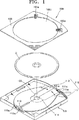
図3は、本発明の望ましい実施例によるディスクカートリッジの分離斜視図であり、図4は、本発明の望ましい実施例によるディスクカートリッジの結合状態を示す斜視図である。 FIG. 3 is an exploded perspective view of a disk cartridge according to a preferred embodiment of the present invention, and FIG. 4 is a perspective view illustrating a coupled state of disk cartridges according to a preferred embodiment of the present invention.
図3および図4を参照すれば、ディスクカートリッジ200は、ディスクプレーヤ(図示せず)に挿入されてディスクDが載置されるターンテーブルと、光ピックアップ装置(図示せず)が位置する開口ホール202が設けられた下部ケース201と、下部ケース201に回動されつつ開閉自在に設置されて下部ケース201との間にディスクDを収納する上部ケース203と、下部ケース201に摺動自在に設置されて開口ホール202を開閉するシャッター210と、シャッター210が開く時にはシャッター210に対して降下し、シャッター210が閉じる時には上昇してディスクDの内周側クランプ領域D1を支持しこれに密着されてディスクDの情報領域D2へのホコリの付着を防止するディスク支え部材240とを具備する。
3 and 4, the
シャッター210は、下部ケース201の内部に相互対称的に回転可能に設置された第1および第2シャッター部211、212よりなる。したがって、第1および第2シャッター部211、212が互いに離れる方向に回転すれば開口ホール202が開放され(図8参照)、逆に互いに近づく方向に回転すれば開口ホール202が閉塞される(図6参照)。参照符号213は、第1および第2シャッター部211、212を連動自在に連結させる連動ギア部であって、それにより第1シャッター部211が回転すれば第2シャッター部212はそれと対称となる方向に共に回転する。そして、第1および第2シャッター部211、212と下部ケース201の底面間には開口ホール202を閉じる方向にそれらを付勢するトーションバネ204が設置されており、オープニングレバー120(図8参照)により加えられた力が除去されればシャッター210を元来の閉鎖状態に復帰させる。
The
そして、第1および第2シャッター部211、212にはディスクDの外周側枠部D3に接触する突出部220、230が形成されている。すなわち、ディスクDには情報が記録される情報領域D2と、ディスクDの内周側クランプ領域D1および情報領域D2外郭の枠部D3の非情報領域とが設けられているが、突出部220、230が枠部D3を支持することによって情報領域D2とシャッター210との接触を回避させる。そして、突出部220、230は、ディスクDが載置された方向に向って傾いた傾斜面221、231を具備する。したがって、第1および第2シャッター部211、212が閉じている時にはディスクDの枠部D3が突出部221、231の上端に支持されているが、第1および第2シャッター部211、212が開けばディスクDが傾斜面221、231に沿って降下する。降下したディスクDは、下部ケース201に形成された第1突起205により内周側クランプ領域D1が支持される。したがって、ディスクDはシャッター211、212と接触しないために、シャッター211、212が開閉される場合にディスクDの情報領域にスクラッチが発生しなくなる。第1および第2シャッター部211、212には突起205が挿入されうるホール215が形成されている。第1および第2シャッター部211、212の背面には複数個の第2突起214が設けられており、これに対応する下部ケース201には、シャッター210が開閉される時に第2突起214が干渉されないようにスロット206が形成されている。したがって、第1および第2シャッター部211、212に外部から力が加えられても、第1および第2シャッター部211、212が第2突起214に支持されてディスクDの情報領域D2に接触することが回避される。
The first and
また、第1および第2シャッター部211、212が閉じた時、中央に貫通ホール218が形成されるようにそれぞれに半楕円形の切除部216が形成されている。これは、上部ケース203を開けてディスクDを取り出す時、ユーザーがディスクDの中央ホールに指を取り出し易くするためのものであり、シャッター210にも貫通ホール218が形成されれば、ディスクDの中央ホールを通じて指をさらに深く入れた後に曲げることができてディスクDの取り出しが容易になるからである。また、ディスクDに向かっているシャッター210の上面にホコリが積もる場合に、シャッター210に形成された貫通ホール218を通じてホコリを外部に排出させるためのものである。
Further, when the first and
後述する傾斜部241aが形成されたスペース形成部241(図5参照)が容易に上昇または降下できるように、傾斜部241aと接触する切除部216は傾いて形成されることが望ましい。
It is desirable that the
図面符号250は、下部ケース201に結合されるバネカバーを示す。
図5は、図3に示したディスク支え部材を拡大した図である。ディスク支え部材240は第1および第2シャッター部211、212にそれぞれ設けられており、全体的な形状が半楕円形であってシャッター210の切除部216に沿って上昇または降下可能に傾斜部241aが形成されているスペース形成部241と、シャッター210に形成されたガイドホール217(図3参照)に沿って摺動自在に設置される摺動部242と、スペース形成部241と摺動部242とを連結してそれ自体が弾性変形可能なレバー部243とを具備する。
FIG. 5 is an enlarged view of the disk support member shown in FIG. The
シャッター210が閉じると、第1および第2シャッター部211、212にそれぞれ設けられたスペース形成部241は切除部216に沿って上昇しつつその両端がそれぞれ当接して、スペース形成部241の上面がディスクDのクランプ領域D3に密着される。シャッター210が開けば、スペース形成部241は切除部216に沿って降下しつつ互いに離れてディスクDのクランプ領域D3から離隔される。
When the
スペース形成部241の上面には、ディスクDのクランプ領域D1と密着してホコリなどの異物が流入されないようにシーリング部材が設けられることが望ましい。このシーリング部材は密着力を受けることによって弾性変形可能な材質、例えば、不織布で製作されることが望ましい。
It is preferable that a sealing member is provided on the upper surface of the
下部ケース201には、シャッター210が開く時、スペース形成部241が挿入されて位置するようにパーキング部208(図3参照)が形成されている。パーキング部208には、スペース形成部241と接触する部分にスペース形成部241の傾斜部241aが容易に摺動できるように傾いて形成されることが望ましい。
The
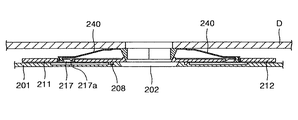
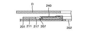
ガイドホール217には、図7および図9に示すように傾斜面217aが設けられている。スペース形成部241が上昇すれば摺動部242もシャッター210の下面から上昇し、スペース形成部241が降下すれば摺動部242も前記シャッターの下面に降下する。すなわち、シャッター210が閉じる時は、摺動部242はシャッター210の下面から上昇した位置に置かれ、スペース形成部241は切除部216に沿って上昇しつつレバー部243が容易に弾性変形可能になる。
The
一方、シャッター210が開く時には、摺動部242はシャッター210の下面側に位置してガイドホール217に挿入されるため、スピンドルモータ(図示せず)は干渉されずに安定的に動作できる。
On the other hand, when the
下部ケース201にはシャッター210が開く時、摺動部242を干渉してスペース形成部241がパーキング部208に円滑に挿入されて位置できるように突設された干渉部207(図3参照)が設けられている。干渉部207は、下部ケース201にシャッター210の最大開き角よりも小さな角内に位置することが望ましい。そして、シャッター210の背面には、シャッター210が開閉される時に干渉部207によって妨害されないように摺動溝(図示せず)が形成されることが望ましい。
When the
上部ケース203には、ディスクドライブ装置に進入してディスクDをクランプするクランプ装置が挿入されうるクランプホール203a(図3参照)が形成されている。クランプホール203aを取り囲む周囲にはシーリング部材260が設けられることが望ましいが、これは、クランプホール203aを通じてホコリなどの異物が流入されることを防止して2次的にディスクDの情報領域D2がホコリなどによって汚染されることを回避できる。シーリング部材260は、ディスクDの外周側枠部D3に接触するように設けられることもある。
The
前記のように本発明の望ましい実施例によるディスクカートリッジの動作を図面を参照して説明する。 The operation of the disk cartridge according to the preferred embodiment of the present invention will be described with reference to the drawings.
図6は、図3に示したディスクカートリッジのシャッター閉鎖状態を示す平面図であり、図7は、図6に示したIV−IV線断面図であり、図8は、図3に示したディスクカートリッジのシャッター開放状態を示す平面図であり、図9は、図8に示したV−V線断面図であり、図10は、シャッターが開く時のディスク支え部材とガイドホールとの動作関係を概略的に示す断面図であり、図11は、シャッターが閉じる時のディスク支え部材とガイドホールとの動作関係を概略的に示す断面図である。 6 is a plan view showing a shutter closed state of the disk cartridge shown in FIG. 3, FIG. 7 is a sectional view taken along line IV-IV shown in FIG. 6, and FIG. 8 is a disk shown in FIG. FIG. 9 is a cross-sectional view taken along the line V-V shown in FIG. 8, and FIG. 10 shows the operational relationship between the disc support member and the guide hole when the shutter is opened. FIG. 11 is a cross-sectional view schematically showing the operational relationship between the disc support member and the guide hole when the shutter is closed.
まず、図8、図9および図10を参照すれば、ディスクDが装着されたディスクカートリッジ200は、図6に示したように上部ケース203が下部ケース201に密着された状態でシャッター210が閉じた状態でディスクドライブ装置(図示せず)内へ進入する。
First, referring to FIG. 8, FIG. 9 and FIG. 10, in the
ディスクカートリッジ200が進入すれば、ディスクドライブ装置に設置されたオープニングレバー120がロック片211aを押して係止部211cから解除させた後、干渉片211bを押して第1シャッター部211を図の反時計回り方向に回転させる。それにより、第2シャッター部212は連動ギア部213により時計回り方向に回転し、第1および第2シャッター部211、212の間に開口ホール202が開放される。この時、ディスクDには第1および第2シャッター部211、212の突出部220、230だけ接触しており、その接触部位も非情報領域であるディスクDの枠部D3に限定されているために、シャッター210の開閉動作時にも記録面の情報領域が損傷を負う危険はほとんどなくなる。そして、シャッター210が開くにつれて、ディスクDは突出部220、230の傾斜面221、231に沿って降下して第1突起205上に一時的に支持される。
When the
ディスク支え部材240は、スペース241形成部241の両端が当接してスペース形成部241の上面がディスクDの内部側のクランプ領域D1に密着接触しており、シャッター210が開くにつれて摺動部242がガイドホール217に沿って移動する。よって、スペース形成部241は切除部216に沿って降下する。摺動部242は、ガイドホール217の傾斜面217aに沿って移動してシャッター210の下面側に移動する。摺動部242が干渉部207に接触しつつスペース形成部241はパーキング部208に挿入されて位置する。
In the
この状態で開放された開口ホール202を通じてディスクドライブ装置のターンテーブルが進入し、上部ケース203のクランプホール203aを通じてクランパーが進入して第1突起205に支持されていたディスクDをクランプする。以後、ターンテーブルの回転駆動と共にディスクDに対する記録および再生作業が行われる。
The turntable of the disk drive device enters through the
次に、図5、図6および図11を参照すれば、記録および再生作業が終了して前記ターンテーブルおよびクランパーによるクランプが解除されれば、ディスクDは一旦第1突起205上にクランプ領域D1が支持された状態に載置される。この状態でディスクカートリッジ200がディスクドライブ装置から離脱すれば第1および第2シャッター部211、212が元来の位置に回動して開口ホール202が閉じるが、この時、ディスクDの外周側枠部D3が突出部220、230の傾斜面221、231に沿って上昇する。したがって、ディスクDの外周側枠部D3は上部ケース203のシーリング部材と密着接触するので、クランプホール203aを通じてホコリが流入されても、ホコリのさらなるディスクDの情報領域D2への流入が防止される。
Next, referring to FIG. 5, FIG. 6, and FIG. 11, when the recording and reproducing operations are completed and the clamp by the turntable and the clamper is released, the disk D is once placed on the
そして、シャッター210が閉じることによって摺動部242は干渉部207との干渉が解除されつつガイドホール217に沿って摺動する。それにより、スペース形成部241はパーキング部208から離隔されて切除部216に沿って上昇する。第1および第2シャッター部211、212が互いに結合されれば、第1および第2シャッター部211、212に設けられたディスク支え部材240のスペース部241は、相互接触しつつディスクDの非情報領域である内周側クランプ領域D1に密着接触してホコリなどの異物が情報領域D2に流入されることを防止する。結果的にディスクDはシーリング部材260によって上部ケース203に密着接触し、ディスク支え部材240によってシャッター210に密着されて上部ケース203および下部ケース201内に固定されているので、ディスクカートリッジ200の移動時に破損の危険が減る。
When the
前述したように、本発明によるディスクカートリッジは、
第1に、シャッターが閉じた状態でもディスクの内周側クランプ領域周囲にディスク支え部材が密着されるために、ホコリの流入を防止してディスクの情報領域が汚染される可能性を減らしうる。
As described above, the disc cartridge according to the present invention is
First, even when the shutter is closed, the disc support member is in close contact with the periphery of the inner peripheral clamp area of the disc, so that the possibility of contamination of the information area of the disc can be reduced by preventing the inflow of dust.
第2に、ディスクの内周側クランプ領域周囲に設けられるディスク支え部材によってディスクが上部ケースおよび下部ケース内に固定されるため、移動時の騷音および破損の危険を減らしうる。 Secondly, since the disc is fixed in the upper case and the lower case by the disc support member provided around the inner peripheral side clamp region of the disc, the risk of noise and damage during movement can be reduced.
Claims (10)
前記下部ケースに回動しつつ開閉自在に設置されて前記下部ケースとの間にディスクを収納する上部ケースと、
前記下部ケースに摺動自在に設置されて前記開口ホールを開閉する一対のシャッターと、
前記各シャッターに摺動自在に設置されて、前記シャッターが閉じる時には突き合わされ前記ディスクの内周側の非情報領域を支持して密着し、前記ディスクの非情報領域と下部ケースとの間を塞ぎ、前記前記シャッターが開く時には前記ディスクの内周側の非情報領域から離れる一対のディスク支え部材とを具備することを特徴とするディスクカートリッジ。A lower case with an opening hole;
An upper case that is installed in the lower case so as to be openable and closable, and that accommodates a disk between the lower case;
A pair of shutters slidably installed in the lower case to open and close the opening hole;
It is slidably installed on each of the shutters, and is abutted when the shutter is closed to support and closely adhere to the non-information area on the inner periphery side of the disk, closing the space between the non-information area of the disk and the lower case. disc cartridge wherein when said shutter is opened, characterized in that it comprises a pair of disc support member away from the non-information area on the inner circumferential side of the disc.
傾斜面を持ち、該傾斜面が前記シャッターに形成された切除部の傾いている面に沿って上昇または降下しつつ前記ディスクの内周側の非情報領域を支持または離隔されるスペース形成部と、
前記シャッターの開閉時に前記シャッターに形成されたガイドホールに沿って摺動する摺動部と、
前記スペース形成部と摺動部とを連結して弾性変形が可能なレバー部とを具備し、
前記一対のディスク支え部材のスペース形成部が突き合わされ、前記ディスクの非情報領域と下部ケースとの間に閉じられたスペースを形成することを特徴とする請求項1に記載のディスクカートリッジ。The disk support member is
It has an inclined surface, and a space forming portion inclined surface is supported or separate the non-information area on the inner circumferential side of the disk rise or drop while being along a plane inclined with cut portion formed on the shutter ,
A sliding portion that slides along a guide hole formed in the shutter when the shutter is opened and closed;
A lever portion capable of elastic deformation by connecting the space forming portion and the sliding portion;
2. The disc cartridge according to claim 1 , wherein the space forming portions of the pair of disc support members are abutted to form a closed space between the non-information area of the disc and the lower case .
該干渉部は、前記シャッターが開く時に前記ディスク支え部材の摺動部を係止して前記ディスク支え部材の移動を停止させ、前記スペース形成部を前記シャッターの端に降下させることを特徴とする請求項2に記載のディスクカートリッジ。In the lower case, an interference part is projected,
The interference portion locks the sliding portion of the disc support member when the shutter is opened to stop the movement of the disc support member, and lowers the space forming portion to the end of the shutter. The disc cartridge according to claim 2.
Applications Claiming Priority (2)
| Application Number | Priority Date | Filing Date | Title |
|---|---|---|---|
| KR1020020009087A KR100813951B1 (en) | 2002-02-20 | 2002-02-20 | A disk cartridge |
| PCT/KR2003/000289 WO2003071541A1 (en) | 2002-02-20 | 2003-02-10 | Disk cartridge |
Publications (2)
| Publication Number | Publication Date |
|---|---|
| JP2005518624A JP2005518624A (en) | 2005-06-23 |
| JP4324666B2 true JP4324666B2 (en) | 2009-09-02 |
Family
ID=27751904
Family Applications (1)
| Application Number | Title | Priority Date | Filing Date |
|---|---|---|---|
| JP2003570351A Expired - Fee Related JP4324666B2 (en) | 2002-02-20 | 2003-02-10 | Disc cartridge |
Country Status (13)
| Country | Link |
|---|---|
| EP (1) | EP1476868B1 (en) |
| JP (1) | JP4324666B2 (en) |
| KR (1) | KR100813951B1 (en) |
| CN (1) | CN1315130C (en) |
| AT (1) | ATE447230T1 (en) |
| AU (1) | AU2003208040A1 (en) |
| CA (1) | CA2476872C (en) |
| DE (1) | DE60329825D1 (en) |
| HK (1) | HK1076187A1 (en) |
| MY (1) | MY134447A (en) |
| RU (1) | RU2275695C2 (en) |
| TW (1) | TWI254922B (en) |
| WO (1) | WO2003071541A1 (en) |
Families Citing this family (2)
| Publication number | Priority date | Publication date | Assignee | Title |
|---|---|---|---|---|
| KR100976480B1 (en) * | 2003-09-16 | 2010-08-18 | 엘지전자 주식회사 | disc detachable disc cartridge |
| KR100959531B1 (en) * | 2003-10-28 | 2010-05-27 | 엘지전자 주식회사 | disc detachable disc cartridge and device for separation disc mounted disc cartridge |
Family Cites Families (9)
| Publication number | Priority date | Publication date | Assignee | Title |
|---|---|---|---|---|
| US4525758A (en) * | 1981-06-19 | 1985-06-25 | Matsushita Electric Industrial Co., Ltd. | Cartridge |
| JPS616974U (en) * | 1984-06-15 | 1986-01-16 | ソニー株式会社 | disk cartridge |
| GB9307293D0 (en) * | 1993-04-07 | 1993-06-02 | Newell Terence J | Optical compact disc sotrage and loading cassette |
| JPH10222946A (en) * | 1997-02-04 | 1998-08-21 | Sony Corp | Disk cartridge |
| US6339583B1 (en) | 1997-06-20 | 2002-01-15 | Hitachi Maxell, Ltd. | Cartridge for information-recording media having deformable elastic member on shutter |
| JP2000113630A (en) * | 1998-10-05 | 2000-04-21 | Sony Corp | Disk cartridge |
| JP2000123521A (en) * | 1998-10-20 | 2000-04-28 | Hitachi Maxell Ltd | Disk cartridge |
| JP3532793B2 (en) * | 1999-05-28 | 2004-05-31 | パイオニア株式会社 | Storage case for disk-type recording media |
| TW522385B (en) * | 2000-05-17 | 2003-03-01 | Sony Corp | Disk cartridge |
-
2002
- 2002-02-20 KR KR1020020009087A patent/KR100813951B1/en not_active IP Right Cessation
-
2003
- 2003-01-28 MY MYPI20030279A patent/MY134447A/en unknown
- 2003-02-07 TW TW092102505A patent/TWI254922B/en not_active IP Right Cessation
- 2003-02-10 EP EP03705443A patent/EP1476868B1/en not_active Expired - Lifetime
- 2003-02-10 WO PCT/KR2003/000289 patent/WO2003071541A1/en active Application Filing
- 2003-02-10 CA CA002476872A patent/CA2476872C/en not_active Expired - Fee Related
- 2003-02-10 RU RU2004125490/28A patent/RU2275695C2/en not_active IP Right Cessation
- 2003-02-10 JP JP2003570351A patent/JP4324666B2/en not_active Expired - Fee Related
- 2003-02-10 DE DE60329825T patent/DE60329825D1/en not_active Expired - Lifetime
- 2003-02-10 AT AT03705443T patent/ATE447230T1/en not_active IP Right Cessation
- 2003-02-10 AU AU2003208040A patent/AU2003208040A1/en not_active Abandoned
- 2003-02-10 CN CNB038086875A patent/CN1315130C/en not_active Expired - Fee Related
-
2005
- 2005-09-16 HK HK05108145A patent/HK1076187A1/en not_active IP Right Cessation
Also Published As
| Publication number | Publication date |
|---|---|
| KR100813951B1 (en) | 2008-03-14 |
| EP1476868A4 (en) | 2006-10-25 |
| KR20030069449A (en) | 2003-08-27 |
| DE60329825D1 (en) | 2009-12-10 |
| TW200306534A (en) | 2003-11-16 |
| AU2003208040A1 (en) | 2003-09-09 |
| ATE447230T1 (en) | 2009-11-15 |
| RU2004125490A (en) | 2005-04-10 |
| RU2275695C2 (en) | 2006-04-27 |
| HK1076187A1 (en) | 2006-01-06 |
| CN1315130C (en) | 2007-05-09 |
| TWI254922B (en) | 2006-05-11 |
| EP1476868A1 (en) | 2004-11-17 |
| WO2003071541A1 (en) | 2003-08-28 |
| CA2476872C (en) | 2008-10-14 |
| CN1647198A (en) | 2005-07-27 |
| JP2005518624A (en) | 2005-06-23 |
| MY134447A (en) | 2007-12-31 |
| CA2476872A1 (en) | 2003-08-28 |
| EP1476868B1 (en) | 2009-10-28 |
Similar Documents
| Publication | Publication Date | Title |
|---|---|---|
| JP2005521187A (en) | Disc cartridge | |
| JP4324666B2 (en) | Disc cartridge | |
| KR100659740B1 (en) | Optical disc and disc cartridge | |
| JPH05159528A (en) | Disc cleaner | |
| JP3818950B2 (en) | Disc cartridge | |
| JP4101764B2 (en) | Disc cartridge | |
| JP4105098B2 (en) | Disc cartridge | |
| KR100823249B1 (en) | A disk cartridge | |
| KR100850704B1 (en) | A disk cartridge | |
| JP4120492B2 (en) | Recording medium cartridge | |
| AU2002359081A1 (en) | Disk cartridge | |
| KR100987450B1 (en) | disc detachable disc cartridge | |
| JP4570849B2 (en) | Disc cartridge | |
| KR100512575B1 (en) | Optical disc and disc cartridge | |
| EP1564156A1 (en) | Case | |
| JPH04195782A (en) | Magnetic disk cartridge | |
| JP2007519157A (en) | Disk drive with disk cartridge | |
| JP2007026561A (en) | Disk cartridge | |
| JPH11213595A (en) | Disk cartridge | |
| JP2008091033A (en) | Recording medium cartridge |
Legal Events
| Date | Code | Title | Description |
|---|---|---|---|
| A621 | Written request for application examination |
Free format text: JAPANESE INTERMEDIATE CODE: A621 Effective date: 20050902 |
|
| A977 | Report on retrieval |
Free format text: JAPANESE INTERMEDIATE CODE: A971007 Effective date: 20080207 |
|
| A131 | Notification of reasons for refusal |
Free format text: JAPANESE INTERMEDIATE CODE: A131 Effective date: 20080219 |
|
| A521 | Request for written amendment filed |
Free format text: JAPANESE INTERMEDIATE CODE: A523 Effective date: 20080519 |
|
| TRDD | Decision of grant or rejection written | ||
| A01 | Written decision to grant a patent or to grant a registration (utility model) |
Free format text: JAPANESE INTERMEDIATE CODE: A01 Effective date: 20090414 |
|
| A01 | Written decision to grant a patent or to grant a registration (utility model) |
Free format text: JAPANESE INTERMEDIATE CODE: A01 |
|
| A61 | First payment of annual fees (during grant procedure) |
Free format text: JAPANESE INTERMEDIATE CODE: A61 Effective date: 20090514 |
|
| FPAY | Renewal fee payment (event date is renewal date of database) |
Free format text: PAYMENT UNTIL: 20120619 Year of fee payment: 3 |
|
| R150 | Certificate of patent or registration of utility model |
Free format text: JAPANESE INTERMEDIATE CODE: R150 |
|
| FPAY | Renewal fee payment (event date is renewal date of database) |
Free format text: PAYMENT UNTIL: 20120619 Year of fee payment: 3 |
|
| FPAY | Renewal fee payment (event date is renewal date of database) |
Free format text: PAYMENT UNTIL: 20130619 Year of fee payment: 4 |
|
| LAPS | Cancellation because of no payment of annual fees |