JP4322651B2 - Mozuku salt storage and draining tank - Google Patents
Mozuku salt storage and draining tank Download PDFInfo
- Publication number
- JP4322651B2 JP4322651B2 JP2003411497A JP2003411497A JP4322651B2 JP 4322651 B2 JP4322651 B2 JP 4322651B2 JP 2003411497 A JP2003411497 A JP 2003411497A JP 2003411497 A JP2003411497 A JP 2003411497A JP 4322651 B2 JP4322651 B2 JP 4322651B2
- Authority
- JP
- Japan
- Prior art keywords
- tank
- mozuku
- draining
- salt
- water
- Prior art date
- Legal status (The legal status is an assumption and is not a legal conclusion. Google has not performed a legal analysis and makes no representation as to the accuracy of the status listed.)
- Expired - Fee Related
Links
- 150000003839 salts Chemical class 0.000 title claims description 52
- 238000003860 storage Methods 0.000 title claims description 28
- XLYOFNOQVPJJNP-UHFFFAOYSA-N water Substances O XLYOFNOQVPJJNP-UHFFFAOYSA-N 0.000 claims description 36
- 238000009938 salting Methods 0.000 claims description 20
- 230000007246 mechanism Effects 0.000 claims description 13
- 239000000203 mixture Substances 0.000 claims 1
- 241000195493 Cryptophyta Species 0.000 description 9
- 230000000007 visual effect Effects 0.000 description 9
- 238000005303 weighing Methods 0.000 description 9
- 238000005406 washing Methods 0.000 description 8
- 238000004519 manufacturing process Methods 0.000 description 7
- 239000003638 chemical reducing agent Substances 0.000 description 5
- 230000003647 oxidation Effects 0.000 description 4
- 238000007254 oxidation reaction Methods 0.000 description 4
- 238000001035 drying Methods 0.000 description 3
- 230000000694 effects Effects 0.000 description 3
- 239000002184 metal Substances 0.000 description 3
- 241000282994 Cervidae Species 0.000 description 2
- 230000009471 action Effects 0.000 description 2
- 230000002950 deficient Effects 0.000 description 2
- 238000007872 degassing Methods 0.000 description 2
- 238000010586 diagram Methods 0.000 description 2
- 238000012856 packing Methods 0.000 description 2
- 238000004080 punching Methods 0.000 description 2
- 229920005989 resin Polymers 0.000 description 2
- 239000011347 resin Substances 0.000 description 2
- 229910001220 stainless steel Inorganic materials 0.000 description 2
- 239000010935 stainless steel Substances 0.000 description 2
- 229920003002 synthetic resin Polymers 0.000 description 2
- 239000000057 synthetic resin Substances 0.000 description 2
- 239000002351 wastewater Substances 0.000 description 2
- 241000282693 Cercopithecidae Species 0.000 description 1
- 230000032683 aging Effects 0.000 description 1
- 238000007599 discharging Methods 0.000 description 1
- 239000012530 fluid Substances 0.000 description 1
- 239000012535 impurity Substances 0.000 description 1
- 239000000463 material Substances 0.000 description 1
- 239000007769 metal material Substances 0.000 description 1
- 238000000034 method Methods 0.000 description 1
- 239000011148 porous material Substances 0.000 description 1
- 230000008569 process Effects 0.000 description 1
- 230000009467 reduction Effects 0.000 description 1
Images


Landscapes
- Edible Seaweed (AREA)
Description
本発明は、モズク塩蔵及び水切り用タンクに係り、特に、タンク内に投入されたモズクの余剰水分を均等・迅速に排水した上でモズクを容易に定量排出できるようにしたものに関する。 The present invention relates to a mozuku salt storage and draining tank, and more particularly, to a moscow that can be easily and quantitatively discharged after draining excess water of the mosk thrown into the tank evenly and quickly.
図8と図9を参照して、従来のモズクの製造プロセス及び塩蔵槽の構成を説明する。まず、塩蔵モズクの場合は、「モズク原藻」Mを「洗浄」Sして「目視選別」S1した後、モズク重量の20%の「塩と混合」S2してから約一日分の処理量に相当する塩蔵槽20(5〜30トン程度)に投入される。続いて、4〜6日間にわたり「塩蔵」S3した後、塩蔵槽底部20Aの排水弁V1を開いて12時間以上にわたり「水切り」S4を行ってモズクMの余剰水分が除去される。このモズクMを「容器」80に排出し、ここで例えば18kgに計量して缶90に充填して「塩蔵モズク」M1を得るものである。また、冷凍モズクの場合は、まず、「モズク原藻」Mを「洗浄」Sして「目視選別」S1した後、2〜30kg程度の量を樹脂製ザルに入れて放置し、「水切り」S4を行ってモズクMの余剰水分を除去する。このモズクMを「容器」80に排出し、ここで例えば16kgに計量して缶90に充填した後「冷凍」S5し、「冷凍モズク」M2を得るものである。
With reference to FIG. 8 and FIG. 9, the structure of the manufacturing process of a conventional mozuku and a salt storage tank is demonstrated. First, in the case of salted mozuku, after “washing” S and “visually sorting” S1 of “mozuku raw algae” M, “mixing with salt” S2 of 20% of mozuku weight is processed for about one day. It is put into a salt storage tank 20 (about 5 to 30 tons) corresponding to the amount. Subsequently, after “salt storage” S3 for 4 to 6 days, the drain valve V1 of the
上記塩蔵モズクM1の塩蔵槽20の構造であるが、図9に示すように、コンクリート製の箱型に形成された塩蔵槽20の底部20Aを片側勾配の傾斜面20Bとし、この傾斜面20Bの低い側に排水用の多孔板23を備え、この多孔板23の外側となる底部20Aの外側に水受部25と配管27及び排水弁V1とを備えている。そして、底部20Aにおける最低部側に面する垂直壁20Cの底部にはモズク排出板29を備え、このものはエアシリンダCOにより昇降させて開閉操作される。上記モズク排出板29の開閉操作により、連像されたモズクは容器80に排出され、更に所定量に計量されて缶90に充填される。(例えば、特許文献1参照。)
上記塩蔵モズクM1の塩蔵槽20は、コンクリート製の箱型形状で構成されたものであるから、塩蔵期間中に高濃度の塩水によりコンクリートにひび割れを生じさせ老化を早めて漏水を起こし、塩蔵モズクの塩分濃度を低下させる。これが原因して、上部のモズクは乾燥と酸化により黒褐色に変質して商品価値を失う。更に、12時間以上水切りを行うと、上部のモズクは水分が不足して乾燥状態が更に進行し、下部は水分の多いモズクとなる。この状態でモズク排出板29を開口してモズクを排出すると、下部の水分の多いモズクは円滑に排出されるものの、上部のモズクは乾燥状態で水分不足となり、流動性を失って排出が困難となるという問題があった。これを防止するために、モズクの水分状態を多少余剰状態としモズクを排出計量することになるが、この場合でも、水分の過剰なモズク計量と、水分の不足したモズク計量とが混在し、不揃いなモズク計量を余儀なくされるという問題があった。この問題は、縦長で大容量の塩蔵槽ほど大きな影響を及ぼしてしまう。
Since the
また、冷凍モズクの場合は、洗浄したモズクは生きているので、大量のモズクを長時間タンクに入れて置くと中心部で発熱して商品価値が低下してしまうことから塩蔵槽の使用はできず、樹脂製ザルによる水切り後に計量充填を行っているが、これでは作業性が悪いという問題があった。 Also, in the case of frozen mozuku, the washed mozuku is alive, so if you put a lot of mozuku in the tank for a long time, it will generate heat at the center and the commercial value will decrease, so you can use a salted tank However, the metering and filling is performed after draining with a resin colander, but this has a problem of poor workability.
本発明はこのような点に基づいてなされたものであってその目的とするところは、タンク内に投入されたモズクの余剰水分を均等・迅速に排水した上でモズクを容易に定量排出できるモズク塩蔵及び水切り用タンクを提供することにある。 The present invention has been made on the basis of the above points, and the object of the present invention is to be able to easily and quantitatively discharge the moscow after draining the excess water of the mosk thrown into the tank evenly and quickly. The object is to provide a tank for salting and draining.
上記目的を達成するべく本発明の請求項1によるモズク塩蔵及び水切り用タンクは、モズクと塩とを混合したもの又は水が付着したモズクを投入可能なタンクと、上記タンク内の壁面ほぼ全面に配置されタンク内面が多孔板で形成されてタンク内と連通された排水室と、上記タンクの下部に形成された樋内に配置されタンク内の排水後のモズクを定量移送可能なスクリューコンベアと、上記樋のスクリューコンベア先端側に配置され開閉機構により開閉可能なモズク排出ゲートと、を具備したことを特徴とするものである。
In order to achieve the above object, a mozuku salt storage and draining tank according to
また、請求項2によるモズク塩蔵及び水切り用タンクは、請求項1記載のモズク塩蔵及び水切り用タンクにおいて、排水室に排水管を介してポンプを接続するとともに、ポンプに先端放出口をタンクの上面に配置された放水管を接続したことを特徴とするものである。
Further, the mozuku salting and draining tank according to
本発明のモズク塩蔵及び水切り用タンクによると、まず、タンク内の壁面のほぼ全面に配置した多孔板から排水室にモズク全体から排水されて余剰水分が均一に水切りされる。そして、タンク下部に配置した定量移送が可能なスクリューコンベアにより、タンク内の排水後のモズクは、スクリューコンベアの先端側の開閉機構に向けて順次に移送される。そして、余剰水分を抜き取り流動性の低下したモズクであっても、開閉機構で開閉操作されるモズク排出ゲートから定量ずつ取り出される。 According to the mozuku salt storage and draining tank of the present invention, first, the entire mozuku is drained from the perforated plate disposed on almost the entire wall surface in the tank to the drainage chamber, and excess water is drained uniformly. Then, the wastewater in the tank is sequentially transferred toward the opening / closing mechanism on the front end side of the screw conveyor by a screw conveyor arranged at the bottom of the tank and capable of quantitative transfer. Even if the moisture is extracted by removing excess water, it is taken out in a fixed amount from the gate discharging gate that is opened and closed by the opening and closing mechanism.
更に、上記モズク塩蔵及び水切り用タンクによると、排水管にポンプを接続し、この先端放出口をタンクの上面に配置された放水管に接続されているから、この放出口から排水室内の水をタンク上部からモズク表面に降り注ぐこととなり、モズク表面の乾燥と酸化が防止されるとともに、タンク内のモズクの塩分濃度が均一化される。 Furthermore, according to the mozuku salting and draining tank, a pump is connected to the drainage pipe, and the tip discharge port is connected to the discharge pipe arranged on the upper surface of the tank. The water drops from the upper part of the tank to the surface of the mozuku, so that the mosk surface is prevented from being dried and oxidized, and the salt concentration of mozuku in the tank is made uniform.
本発明によると、タンク内のほぼ全面に多孔板を有する排水室を形成したから、全面排水でモズクの余剰水分を均等・迅速に排出できる。そして、タンク底部に樋とスクリューコンベアと開閉機構付のモズク排出ゲートを設けたから、余剰水分を充分除去し流動性が低下したモズクであっても、容易に定量取り出しができる。 According to the present invention, since the drainage chamber having the perforated plate is formed on almost the entire surface of the tank, the excessive moisture of the mozuku can be discharged evenly and quickly by the drainage of the entire surface. And, since the tank bottom portion is provided with a basket, a screw conveyor and a moscow discharge gate with an opening / closing mechanism, it is possible to easily take out a quantitative amount even if the moisturized water is sufficiently removed and its fluidity is lowered.
また、排水室にポンプを接続し、ポンプに先端放出口をタンクの上面に配置された放水管を接続したから、塩蔵中に排水室内の水をタンクの上面からモズク表面に降り注ぐことで乾燥と酸化を防止するとともに、タンク内のモズクの塩分濃度を均一化して、モズクの品質を高めることができる。 In addition, since a pump was connected to the drainage chamber and a water discharge pipe with a tip discharge port located on the upper surface of the tank was connected to the pump, the water in the drainage chamber was poured from the upper surface of the tank onto the mozuku surface during salting and dried. While preventing oxidation, the salt concentration of mozuku in the tank can be made uniform, and mozuku quality can be improved.
以下、図1乃至図8を参照して本発明の第1の実施の形態を説明する。図1はモズクを製造する生産システムの構成図、図2はモズク塩蔵及び水切り用タンクの斜視図、図3は平面図である。更に、図4はモズク塩蔵及び水切り用タンクの正断面図、図5は要部の拡大作用図、図6はモズク塩蔵及び水切り用タンクの側面図、図7は作用断面図、図8はモズクを製造する工程のフローチャート図である。 Hereinafter, a first embodiment of the present invention will be described with reference to FIGS. FIG. 1 is a configuration diagram of a production system for producing mozuku, FIG. 2 is a perspective view of mozuku salting and draining tank, and FIG. 3 is a plan view. Further, FIG. 4 is a front sectional view of a mozuku salting and draining tank, FIG. 5 is an enlarged view of the main part, FIG. 6 is a side view of the mozuku salting and draining tank, FIG. 7 is a working sectional view, and FIG. It is a flowchart figure of the process of manufacturing.
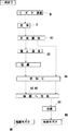
まず、モズクを製造する生産システムの構成から説明する。図1に示すように、モズク原藻Mは、定量供給架台1から定量供給スクリュー2に投入される。この投入されたモズク原藻Mは、一次洗浄機3から二次洗浄機4を介して水切り目視コンベアー5と目視選別コンベアー6とで洗浄されるとともに不純物が作業者の手により除去される。続いて、洗浄ホッパー7に送り込まれたモズク原藻Mは、混合機送りポンプ8により混合機9に送り込まれる。また、混合機9には、モズク塩計量装置10で計量された塩が塩供給装置11から投入される。通常、モズク重量の20%の塩が混合される。塩蔵モズクM1は、混合機ホッパー12に取り出され、塩蔵タンク送りポンプ14により、本発明のタンク31(5〜7基を並設)に約一日分の処理量(5〜30トン程度)が投入される。タンク31は塩蔵槽の機能を発揮するものであり、この中でモズクを4〜6日間にわたり塩蔵した後、タンク31底部の排水弁を開いて6時間(従来の1/2位の時間)で水切りを行って塩蔵モズクM1の余剰水分を除去する。この塩蔵モズクM1を目視選別計量台15に定量排出(例えば500kg〜1トンの重量)し、例えば18kgの塩蔵モズクM1を容器に充填し、脱気クリップ装置17で脱気し、梱包機18で梱包して搬送可能な缶入り塩蔵モズクをM1得るものである。
First, the configuration of a production system for producing mozuku will be described. As shown in FIG. 1, mozuku raw algae M are fed from a
また、冷凍生モズクM2を製造する場合であってモズク塩蔵及び水切り用タンク100を生モズクの水切りタンクとして使用する場合は、モズク原藻Mを塩と混合することなく、約一日分の処理量をタンク31に投入する。この場合は、タンク31は一時的な貯蔵槽の機能を発揮するものであり、投入後直ちに水切りを開始し、6時間位水切りを行って生モズクMの余剰水分を除去する。この生モズクMを目視選別計量台15に定量排出(例えば500kg〜1トンの重量)し、例えば16kgの生モズクMを容器に充填し、脱気クリップ装置17で脱気し、冷凍庫で冷凍し、冷凍生モズクM2を得るものである。
In addition, when the frozen raw mozuku M2 is manufactured and the mozuku salt storage and draining
次に、図2乃至図8を参照してモズク塩蔵及び水切り用タンク100の構成を説明する。図2に示すように、4本の柱30A〜30Dによって枠組されたフレームFの上部には、ステンレス材等の金属材又は合成樹脂材で形成された四角形の塩蔵タンク31が取り付けられている。このタンク31は、下方位置に配置したスクリューコンベア40に向けて先すぼまり形状になっている。尚、タンク形状は、垂直壁面の全体を傾斜させたホッパー状としても良いし、片側だけを傾斜面としても良いし、全体の形状をお椀形としても良い。
Next, the structure of the mozuku salt storage and draining
そして、図7に示すように、上記タンク31内における側壁面31A〜31Dと底部の傾斜面31E,31Fのほぼ全面には排水室37が設けられ、この各排水室37の内側となるタンク31内面には、ステンレス材等の金属製又は合成樹脂製の多孔板33A〜33D及び33E,33Fが設けられている。各排水室37には排水管P1〜P4と連通される排水口35が設けられている。多孔板33A〜33D及び33E,33Fは、例えば、パンチングメタルが使用される。そして、このものは、排水室37に対して、着脱可能に取り付けられている。これは、多孔板33A〜33D及び33E,33F自体や排水室37内を清掃できるようにするためである。上記多孔板33A〜33D及び33E,33Fの孔径は、モズク原藻Mを通過させない大きさ(例えば、直径6〜8mm)に設定されている。尚、上記多孔板33A〜33D及び33E,33Fは、タンク31内面における全面に設けなくてもその機能が果たせれば全面よりは少ない範囲に設置することも可能であり、相当程度広範囲にわたって設けられていれば良いものである。
As shown in FIG. 7,
上記各排水口35に繋がれた排水管P1〜P4は、排水弁V1に接続されるとともに、一本の配管P5に接続した循環ポンプPを介してタンク31の上部に放水管P6として立ち上げられ、先端放出口39をタンク31の上面に配置して開閉弁V2〜V4の開閉操作により散水される。しかして、上記タンク31の側面及び底面から回収した水(塩水)Wは、循環ポンプPにより塩蔵モズクM1の表面に循環して散水される。この散水は定期的又は連続的に行われる。塩蔵後の水切りは、排水弁V1を開口させることにより、タンク31の側面及び底面から一斉に水(塩水)Wを回収して外部へ排出される。
The drainage pipes P1 to P4 connected to the
上記タンク31の最下部31Gに形成された樋31Hには、搬送手段となるスクリューコンベア40のスクリュー40Aが水平方向に配置されている。このスクリューコンベア40は、図2〜図4に示すように、タンク31の最下部31Gを左右に貫通する長い樋31Hの片側に装備した減速機付モータMOのスプロケット41とスクリュー40Aの片側のスプロケット43とがチェーンCによって繋がれ、減速機付モータMOの回転駆動力により低速回転される。上記スクリューコンベア40により、排水後の塩蔵タンク31内の塩蔵モズクM1又はモズクMを定量移送することが可能となる。
A
上記塩蔵タンク31の底部に配置したスクリューコンベア40には、樋31Hの先端側の下面にモズク排出ゲート50が設けられている。このモズク排出ゲート50には、開閉板51を開閉可能な開閉機構60を備えている。上記開閉機構60は、図4と図5に示すように、減速機付モータMGのスプロケット61と進退杆63の駆動ピニオン65のスプロケット67とがチェーンCによって繋がれ、減速機付モータMGの正転・逆転により、開閉板51を実線で示すモズク排出ゲート50の開口位置と鎖線で示す閉口位置に進退移動する。上記開閉板51は、進退レール70,71上を開閉板51の下面に付設したローラ73,75により案内され、円滑な進退移動ができるように構成されている。尚、上記開閉板51は、進退杆63を複動シリンダによって駆動させるようにすることも可能である。
The
以上の構成を基にその作用を説明する。塩蔵モズクM1を製造するモズク塩蔵及び水切り用タンク100とした場合は、図7と図8に示すように、まず、モズク原藻Mを洗浄Sして目視選別S1する。このモズク重量の20%の塩と混合した塩蔵モズクM1は、約一日分の処理量(5〜30トン程度)がタンク31に投入される。そして、4〜6日間にわたり「塩蔵」S3する。この「塩蔵」S3の期間中に、排水弁V1を閉じるとともに、一本の配管P5に接続した循環ポンプPを介してタンク31の上部の先端放出口39からタンク31の上面に散水される。これで、上記タンク31の側面及び底面から回収した水(塩水)Wは、循環ポンプPにより塩蔵モズクM1の表面に循環して散水される。これにより、放出口から塩蔵中に排水室内の水をタンク上部からモズク表面に降り注ぐこととなり、モズク表面の乾燥と酸化が防止される。更に、塩蔵期間中の塩蔵モズクM1は、タンクの上下位置や表面に関係なく、水分と塩分濃度が均等になり、その品質が均一に維持される。
The operation will be described based on the above configuration. In the case of the mozuku salting and draining
続いて、塩蔵期間後は、排水弁V1を開いてタンク31の各壁面に設けた多孔板33A〜33D及び33E,33Fから6時間以上にわたり「水切り」S4を行ってタンク内の全面から水(塩水)Wを排水し、排水室から排水弁V1を通じて外部へ排出される。これにより、タンク31内の塩蔵モズクM1は、タンク側壁面のほほ全面に配置した多孔板から排水されるので、タンク31の上部や底部等の位置に関係なくモズク全体から余剰水分が均等に排出され、迅速に水切りされる。
Subsequently, after the salt storage period, the drainage valve V1 is opened and “draining” S4 is performed for 6 hours or more from the
上記排水後、タンク31底部に水平方向に配置した定量移送が可能なスクリューコンベア40を駆動させ、タンク31内の排水後の塩蔵モズクM1をこのスクリューコンベア40の先端側のモズク排出ゲート50に向けて順次移送させる。モズク排出ゲート50に到達した塩蔵モズクM1は、開閉機構60による開閉板51の開口操作で目視選別計量台15に定量ずつ排出される。この時、タンク31の形状はホッパー状(先すぼまり状)としたので、塩蔵モズクM1の流動性が低下していても円滑にスクリューコンベア40に流れ込み、この先端側のモズク排出ゲート50に向けて順次移送されることになる。これにより、塩蔵モズクM1が正確に容器80に定量排出され、缶90に(例えば18kg)充填される。しかして、缶90に充填された塩蔵モズクの正味量が均一となり、商品の均一性を高められる。
After the drainage, the
また、冷凍モズクM2のモズク塩蔵及び水切り用タンク100として使用する場合は、洗浄により多くの付着水分を有するモズク原藻Mを、約一日分の処理量タンク31に投入する。このとき、排水弁V1を開放しておき、6時間以上にわたり水切りを行ってモズクMの余剰水分を除去する。そして、上記と同様に生モズクMを容器80に定量排出して、缶90に(例えば16kg)充填した後、冷凍し、冷凍生モズクM2を得るものである。具体的な実施例としては、タンク31は3基程度使用し、洗浄したモズクをタンクaに8〜9時、タンクbに9〜10時、タンクcに10時〜11時に順次投入される。タンクaに投入されたモズクは直ちに水切りが行われ、モズクがタンクcに投入される10〜11時までには目視選別計量台15に排出される。以下順次タンクb内のモズクは11〜12時、タンクc内のモズクは12〜13時に排出される。その他の作用は、上記塩蔵モズクM1の製造と同一であるから説明を省略する。
When the frozen mozuku M2 is used as the mozuku salting and draining
以上本実施の形態によると次のような効果を奏することができる。まず、タンク31のほぼ全面に多孔板33を有する排水室37を形成したから、タンク31のほぼ全面からの排水でモズク中の余剰水分を均等に水切りできる。従って、タンク31内のモズク全体の水分を高度に除去することができる。そして、タンク31底部に樋とスクリューコンベア40と開閉機構60付のモズク排出ゲート50を設けたから、余剰水分を充分除去し流動性が低下していても、容易に定量取り出しができる。
As described above, according to the present embodiment, the following effects can be obtained. First, since the
また、排水室37にポンプPを接続し、ポンプPに先端放出口をタンクの上面に配置された放水管39を接続したから、塩蔵中に排水室37内の水や塩水Wをタンクの上面からモズク表面に降り注ぐことで乾燥と酸化を防止するとともにタンク内のモズクの塩分濃度を均一にできる。これにより、モズクの品質を高めることができる。
Further, since the pump P is connected to the
尚、本発明は上記第1の実施の形態に限定されるものではない。例えば、スクリューコンベアから排出されるモズクを受ける容器の下部に計量装置を設け、スクリューコンベアの減速機付きモータと連携させることにより、自動計量充填を行うこともできる。また、多孔板33はパンチングメタルを使用したが、メッシュ、金網を使用することも可能である。また、スクリューコンベアの先端側に設けた開閉機構60は、開閉板51を進退駆動するものから回動駆動される開閉機構としても良い。上記実施の形態の変更によっても同様な作用・効果を奏することができる。
The present invention is not limited to the first embodiment. For example, automatic weighing and filling can also be performed by providing a weighing device in the lower part of a container that receives a moose discharged from a screw conveyor and linking it with a motor with a speed reducer of the screw conveyor. Moreover, although the
本発明は、モズク塩蔵及び水切り用タンクとしての実施の形態で説明したが、それに限定されるものではなく、水分を含んだ流動体の塩蔵及び水切りタンクにも適用可能である。 Although the present invention has been described in the embodiment as a mozuku salting and draining tank, the present invention is not limited to this, and can also be applied to a fluid salting and draining tank containing moisture.
1 定量供給架台
2 定量供給スクリュー
3 一次洗浄機
4 二次洗浄機
5,6 目視コンベアー
7 洗浄ホッパー
8 混合機送りポンプ
9 混合機
10 モズク塩計量装置
11 塩供給装置
12 混合機ホッパー
14 塩蔵槽送りポンプ
15 目視選別計量台
17 脱気クリップ装置
18 梱包機
31 タンク
31A〜31D 側壁面
31E,31F 底部の傾斜面
31G 最下部
31H 樋
33A〜33F 多孔板
35 排水口
37 排水室
39 先端放出口
40 スクリューコンベア
40A スクリュー
41,43 スプロケット
50 モズク排出ゲート
51 開閉板
60 開閉機構
61 スプロケット
63 進退杆
65 駆動ピニオン
67 スプロケット
70,71 進退レール
73,75 ローラ
80 容器
90 缶
100 モズク塩蔵及び水切り用タンク
C チェーン
CO エアシリンダ
M モズク原藻
M1 塩蔵モズク
M2 冷凍モズク
MO 減速機付モータ
MG 減速機付モータ
P 循環ポンプ
P1〜P4 排水管
P5 配管
P6 放水管
S 洗浄
S1 目視選別
S2 塩と混合
S3 塩蔵
S4 水切り
S5 冷凍
V1 排水弁
V2〜V4 開閉弁
W 水(塩水)
DESCRIPTION OF
Claims (2)
2. A mozuku salting and draining tank according to claim 1, wherein a pump is connected to the drainage chamber via a drainage pipe, and a water discharge pipe having a tip discharge port disposed on the upper surface of the tank is connected to the pump.
Priority Applications (1)
| Application Number | Priority Date | Filing Date | Title |
|---|---|---|---|
| JP2003411497A JP4322651B2 (en) | 2003-12-10 | 2003-12-10 | Mozuku salt storage and draining tank |
Applications Claiming Priority (1)
| Application Number | Priority Date | Filing Date | Title |
|---|---|---|---|
| JP2003411497A JP4322651B2 (en) | 2003-12-10 | 2003-12-10 | Mozuku salt storage and draining tank |
Publications (2)
| Publication Number | Publication Date |
|---|---|
| JP2005168369A JP2005168369A (en) | 2005-06-30 |
| JP4322651B2 true JP4322651B2 (en) | 2009-09-02 |
Family
ID=34732212
Family Applications (1)
| Application Number | Title | Priority Date | Filing Date |
|---|---|---|---|
| JP2003411497A Expired - Fee Related JP4322651B2 (en) | 2003-12-10 | 2003-12-10 | Mozuku salt storage and draining tank |
Country Status (1)
| Country | Link |
|---|---|
| JP (1) | JP4322651B2 (en) |
Families Citing this family (2)
| Publication number | Priority date | Publication date | Assignee | Title |
|---|---|---|---|---|
| KR101785026B1 (en) * | 2015-11-18 | 2017-10-12 | 삼성중공업 주식회사 | Bulk tank |
| CN109288422A (en) * | 2018-11-29 | 2019-02-01 | 金同磊 | Saltcellar |
-
2003
- 2003-12-10 JP JP2003411497A patent/JP4322651B2/en not_active Expired - Fee Related
Also Published As
| Publication number | Publication date |
|---|---|
| JP2005168369A (en) | 2005-06-30 |
Similar Documents
| Publication | Publication Date | Title |
|---|---|---|
| DE2525749A1 (en) | WASHING EQUIPMENT FOR CRUSHED PLASTIC FILMS AND TAPES | |
| CN210125197U (en) | Food processing is with abluent oil water separator of being convenient for | |
| UA47391C2 (en) | Method and apparatus for extraction of soluble solids from raw materials | |
| JP4322651B2 (en) | Mozuku salt storage and draining tank | |
| CN113318511B (en) | Premixed concrete waste water recycle device | |
| CN210058016U (en) | Proportioning device is used in production of high-efficient compound fertilizer | |
| US2980538A (en) | Process and apparatus for washing curd for cottage cheese | |
| CN109833646A (en) | A kind of powder infuser | |
| CN206216917U (en) | A kind of damping scraper type concrete central mix plant | |
| CN209790931U (en) | Oil cake extraction system | |
| US5601706A (en) | Sewage treatment apparatus including aggregate separator | |
| JP4532126B2 (en) | Mozuku algae quantitative supply equipment | |
| CN211069971U (en) | Liquid pouring device used in production of spices and essences | |
| CN110921250B (en) | Intelligent preserved fruit adding and stirring device and using method thereof | |
| CN211051331U (en) | Batching jar convenient to clearance | |
| WO2018087544A1 (en) | Separator apparatus and method | |
| CN209790935U (en) | Powder extraction system | |
| JP4611848B2 (en) | Waste liquid treatment equipment | |
| CN112813290A (en) | Rare earth element extraction device for wastewater treatment | |
| CN207375853U (en) | A kind of municipal sewage pretreatment unit | |
| CN219597501U (en) | Rice processing belt cleaning device | |
| RU75275U1 (en) | OIL MANUFACTURER | |
| JPS62232358A (en) | De-fatting tank for ground fish production device | |
| CN217257279U (en) | Automatic feeding and stirring device for foam concrete processing | |
| CN219155370U (en) | Ferment holding vessel |
Legal Events
| Date | Code | Title | Description |
|---|---|---|---|
| A621 | Written request for application examination |
Free format text: JAPANESE INTERMEDIATE CODE: A621 Effective date: 20061205 |
|
| A977 | Report on retrieval |
Free format text: JAPANESE INTERMEDIATE CODE: A971007 Effective date: 20090331 |
|
| TRDD | Decision of grant or rejection written | ||
| A01 | Written decision to grant a patent or to grant a registration (utility model) |
Free format text: JAPANESE INTERMEDIATE CODE: A01 Effective date: 20090512 |
|
| A01 | Written decision to grant a patent or to grant a registration (utility model) |
Free format text: JAPANESE INTERMEDIATE CODE: A01 |
|
| A61 | First payment of annual fees (during grant procedure) |
Free format text: JAPANESE INTERMEDIATE CODE: A61 Effective date: 20090603 |
|
| R150 | Certificate of patent or registration of utility model |
Ref document number: 4322651 Country of ref document: JP Free format text: JAPANESE INTERMEDIATE CODE: R150 Free format text: JAPANESE INTERMEDIATE CODE: R150 |
|
| FPAY | Renewal fee payment (event date is renewal date of database) |
Free format text: PAYMENT UNTIL: 20120612 Year of fee payment: 3 |
|
| FPAY | Renewal fee payment (event date is renewal date of database) |
Free format text: PAYMENT UNTIL: 20130612 Year of fee payment: 4 |
|
| R250 | Receipt of annual fees |
Free format text: JAPANESE INTERMEDIATE CODE: R250 |
|
| R250 | Receipt of annual fees |
Free format text: JAPANESE INTERMEDIATE CODE: R250 |
|
| R250 | Receipt of annual fees |
Free format text: JAPANESE INTERMEDIATE CODE: R250 |
|
| R250 | Receipt of annual fees |
Free format text: JAPANESE INTERMEDIATE CODE: R250 |
|
| R250 | Receipt of annual fees |
Free format text: JAPANESE INTERMEDIATE CODE: R250 |
|
| R250 | Receipt of annual fees |
Free format text: JAPANESE INTERMEDIATE CODE: R250 |
|
| R250 | Receipt of annual fees |
Free format text: JAPANESE INTERMEDIATE CODE: R250 |
|
| R250 | Receipt of annual fees |
Free format text: JAPANESE INTERMEDIATE CODE: R250 |
|
| R250 | Receipt of annual fees |
Free format text: JAPANESE INTERMEDIATE CODE: R250 |
|
| R250 | Receipt of annual fees |
Free format text: JAPANESE INTERMEDIATE CODE: R250 |
|
| R250 | Receipt of annual fees |
Free format text: JAPANESE INTERMEDIATE CODE: R250 |
|
| LAPS | Cancellation because of no payment of annual fees |