JP4321663B2 - Electrostatic liquid ejector - Google Patents
Electrostatic liquid ejector Download PDFInfo
- Publication number
- JP4321663B2 JP4321663B2 JP2008283240A JP2008283240A JP4321663B2 JP 4321663 B2 JP4321663 B2 JP 4321663B2 JP 2008283240 A JP2008283240 A JP 2008283240A JP 2008283240 A JP2008283240 A JP 2008283240A JP 4321663 B2 JP4321663 B2 JP 4321663B2
- Authority
- JP
- Japan
- Prior art keywords
- pressure
- chamber
- plate
- displacement plate
- ink
- Prior art date
- Legal status (The legal status is an assumption and is not a legal conclusion. Google has not performed a legal analysis and makes no representation as to the accuracy of the status listed.)
- Expired - Fee Related
Links
- 239000007788 liquid Substances 0.000 title claims description 23
- 238000006073 displacement reaction Methods 0.000 claims description 102
- 230000007423 decrease Effects 0.000 claims description 9
- 238000007599 discharging Methods 0.000 claims description 3
- 239000000758 substrate Substances 0.000 description 30
- 239000011521 glass Substances 0.000 description 22
- 238000010586 diagram Methods 0.000 description 12
- 238000004891 communication Methods 0.000 description 11
- 238000001514 detection method Methods 0.000 description 11
- 238000010438 heat treatment Methods 0.000 description 8
- 230000036961 partial effect Effects 0.000 description 8
- 230000002829 reductive effect Effects 0.000 description 8
- ZOXJGFHDIHLPTG-UHFFFAOYSA-N Boron Chemical compound [B] ZOXJGFHDIHLPTG-UHFFFAOYSA-N 0.000 description 7
- 229910052796 boron Inorganic materials 0.000 description 7
- XUIMIQQOPSSXEZ-UHFFFAOYSA-N Silicon Chemical compound [Si] XUIMIQQOPSSXEZ-UHFFFAOYSA-N 0.000 description 6
- 238000007789 sealing Methods 0.000 description 6
- 229910052710 silicon Inorganic materials 0.000 description 6
- 239000010703 silicon Substances 0.000 description 6
- 238000005530 etching Methods 0.000 description 4
- 238000004519 manufacturing process Methods 0.000 description 4
- 239000004065 semiconductor Substances 0.000 description 4
- 230000003247 decreasing effect Effects 0.000 description 3
- 239000000463 material Substances 0.000 description 3
- 238000000034 method Methods 0.000 description 3
- 239000002699 waste material Substances 0.000 description 3
- 238000006243 chemical reaction Methods 0.000 description 2
- 239000003205 fragrance Substances 0.000 description 2
- 239000000446 fuel Substances 0.000 description 2
- 238000002347 injection Methods 0.000 description 2
- 239000007924 injection Substances 0.000 description 2
- 230000001902 propagating effect Effects 0.000 description 2
- 230000001681 protective effect Effects 0.000 description 2
- 239000000565 sealant Substances 0.000 description 2
- 239000010409 thin film Substances 0.000 description 2
- 238000010521 absorption reaction Methods 0.000 description 1
- 230000002411 adverse Effects 0.000 description 1
- 230000015572 biosynthetic process Effects 0.000 description 1
- 238000009530 blood pressure measurement Methods 0.000 description 1
- 239000005388 borosilicate glass Substances 0.000 description 1
- 238000002485 combustion reaction Methods 0.000 description 1
- 239000004020 conductor Substances 0.000 description 1
- 238000001816 cooling Methods 0.000 description 1
- 239000000428 dust Substances 0.000 description 1
- 239000010408 film Substances 0.000 description 1
- 239000006260 foam Substances 0.000 description 1
- PCHJSUWPFVWCPO-UHFFFAOYSA-N gold Chemical compound [Au] PCHJSUWPFVWCPO-UHFFFAOYSA-N 0.000 description 1
- 239000010931 gold Substances 0.000 description 1
- 229910052737 gold Inorganic materials 0.000 description 1
- 238000005304 joining Methods 0.000 description 1
- 238000005192 partition Methods 0.000 description 1
- 238000005498 polishing Methods 0.000 description 1
- 238000000638 solvent extraction Methods 0.000 description 1
- 238000004544 sputter deposition Methods 0.000 description 1
- 239000000126 substance Substances 0.000 description 1
- MZLGASXMSKOWSE-UHFFFAOYSA-N tantalum nitride Chemical compound [Ta]#N MZLGASXMSKOWSE-UHFFFAOYSA-N 0.000 description 1
- 238000007740 vapor deposition Methods 0.000 description 1
Images


Classifications
-
- B—PERFORMING OPERATIONS; TRANSPORTING
- B41—PRINTING; LINING MACHINES; TYPEWRITERS; STAMPS
- B41J—TYPEWRITERS; SELECTIVE PRINTING MECHANISMS, i.e. MECHANISMS PRINTING OTHERWISE THAN FROM A FORME; CORRECTION OF TYPOGRAPHICAL ERRORS
- B41J2/00—Typewriters or selective printing mechanisms characterised by the printing or marking process for which they are designed
- B41J2/005—Typewriters or selective printing mechanisms characterised by the printing or marking process for which they are designed characterised by bringing liquid or particles selectively into contact with a printing material
- B41J2/01—Ink jet
- B41J2/135—Nozzles
- B41J2/16—Production of nozzles
- B41J2/1621—Manufacturing processes
- B41J2/1626—Manufacturing processes etching
-
- B—PERFORMING OPERATIONS; TRANSPORTING
- B41—PRINTING; LINING MACHINES; TYPEWRITERS; STAMPS
- B41J—TYPEWRITERS; SELECTIVE PRINTING MECHANISMS, i.e. MECHANISMS PRINTING OTHERWISE THAN FROM A FORME; CORRECTION OF TYPOGRAPHICAL ERRORS
- B41J2/00—Typewriters or selective printing mechanisms characterised by the printing or marking process for which they are designed
- B41J2/005—Typewriters or selective printing mechanisms characterised by the printing or marking process for which they are designed characterised by bringing liquid or particles selectively into contact with a printing material
- B41J2/01—Ink jet
- B41J2/135—Nozzles
- B41J2/14—Structure thereof only for on-demand ink jet heads
- B41J2/14314—Structure of ink jet print heads with electrostatically actuated membrane
-
- B—PERFORMING OPERATIONS; TRANSPORTING
- B41—PRINTING; LINING MACHINES; TYPEWRITERS; STAMPS
- B41J—TYPEWRITERS; SELECTIVE PRINTING MECHANISMS, i.e. MECHANISMS PRINTING OTHERWISE THAN FROM A FORME; CORRECTION OF TYPOGRAPHICAL ERRORS
- B41J2/00—Typewriters or selective printing mechanisms characterised by the printing or marking process for which they are designed
- B41J2/005—Typewriters or selective printing mechanisms characterised by the printing or marking process for which they are designed characterised by bringing liquid or particles selectively into contact with a printing material
- B41J2/01—Ink jet
- B41J2/135—Nozzles
- B41J2/16—Production of nozzles
- B41J2/1621—Manufacturing processes
- B41J2/1623—Manufacturing processes bonding and adhesion
-
- B—PERFORMING OPERATIONS; TRANSPORTING
- B41—PRINTING; LINING MACHINES; TYPEWRITERS; STAMPS
- B41J—TYPEWRITERS; SELECTIVE PRINTING MECHANISMS, i.e. MECHANISMS PRINTING OTHERWISE THAN FROM A FORME; CORRECTION OF TYPOGRAPHICAL ERRORS
- B41J2/00—Typewriters or selective printing mechanisms characterised by the printing or marking process for which they are designed
- B41J2/005—Typewriters or selective printing mechanisms characterised by the printing or marking process for which they are designed characterised by bringing liquid or particles selectively into contact with a printing material
- B41J2/01—Ink jet
- B41J2/135—Nozzles
- B41J2/16—Production of nozzles
- B41J2/1621—Manufacturing processes
- B41J2/164—Manufacturing processes thin film formation
- B41J2/1642—Manufacturing processes thin film formation thin film formation by CVD [chemical vapor deposition]
-
- B—PERFORMING OPERATIONS; TRANSPORTING
- B41—PRINTING; LINING MACHINES; TYPEWRITERS; STAMPS
- B41J—TYPEWRITERS; SELECTIVE PRINTING MECHANISMS, i.e. MECHANISMS PRINTING OTHERWISE THAN FROM A FORME; CORRECTION OF TYPOGRAPHICAL ERRORS
- B41J2/00—Typewriters or selective printing mechanisms characterised by the printing or marking process for which they are designed
- B41J2/005—Typewriters or selective printing mechanisms characterised by the printing or marking process for which they are designed characterised by bringing liquid or particles selectively into contact with a printing material
- B41J2/01—Ink jet
- B41J2/135—Nozzles
- B41J2/16—Production of nozzles
- B41J2/1621—Manufacturing processes
- B41J2/164—Manufacturing processes thin film formation
- B41J2/1646—Manufacturing processes thin film formation thin film formation by sputtering
-
- B—PERFORMING OPERATIONS; TRANSPORTING
- B41—PRINTING; LINING MACHINES; TYPEWRITERS; STAMPS
- B41J—TYPEWRITERS; SELECTIVE PRINTING MECHANISMS, i.e. MECHANISMS PRINTING OTHERWISE THAN FROM A FORME; CORRECTION OF TYPOGRAPHICAL ERRORS
- B41J2/00—Typewriters or selective printing mechanisms characterised by the printing or marking process for which they are designed
- B41J2/005—Typewriters or selective printing mechanisms characterised by the printing or marking process for which they are designed characterised by bringing liquid or particles selectively into contact with a printing material
- B41J2/01—Ink jet
- B41J2/135—Nozzles
- B41J2/14—Structure thereof only for on-demand ink jet heads
- B41J2002/14387—Front shooter
-
- B—PERFORMING OPERATIONS; TRANSPORTING
- B41—PRINTING; LINING MACHINES; TYPEWRITERS; STAMPS
- B41J—TYPEWRITERS; SELECTIVE PRINTING MECHANISMS, i.e. MECHANISMS PRINTING OTHERWISE THAN FROM A FORME; CORRECTION OF TYPOGRAPHICAL ERRORS
- B41J2/00—Typewriters or selective printing mechanisms characterised by the printing or marking process for which they are designed
- B41J2/005—Typewriters or selective printing mechanisms characterised by the printing or marking process for which they are designed characterised by bringing liquid or particles selectively into contact with a printing material
- B41J2/01—Ink jet
- B41J2/135—Nozzles
- B41J2/14—Structure thereof only for on-demand ink jet heads
- B41J2002/14411—Groove in the nozzle plate
-
- B—PERFORMING OPERATIONS; TRANSPORTING
- B41—PRINTING; LINING MACHINES; TYPEWRITERS; STAMPS
- B41J—TYPEWRITERS; SELECTIVE PRINTING MECHANISMS, i.e. MECHANISMS PRINTING OTHERWISE THAN FROM A FORME; CORRECTION OF TYPOGRAPHICAL ERRORS
- B41J2202/00—Embodiments of or processes related to ink-jet or thermal heads
- B41J2202/01—Embodiments of or processes related to ink-jet heads
- B41J2202/03—Specific materials used
-
- Y—GENERAL TAGGING OF NEW TECHNOLOGICAL DEVELOPMENTS; GENERAL TAGGING OF CROSS-SECTIONAL TECHNOLOGIES SPANNING OVER SEVERAL SECTIONS OF THE IPC; TECHNICAL SUBJECTS COVERED BY FORMER USPC CROSS-REFERENCE ART COLLECTIONS [XRACs] AND DIGESTS
- Y10—TECHNICAL SUBJECTS COVERED BY FORMER USPC
- Y10T—TECHNICAL SUBJECTS COVERED BY FORMER US CLASSIFICATION
- Y10T29/00—Metal working
- Y10T29/42—Piezoelectric device making
Landscapes
- Engineering & Computer Science (AREA)
- Manufacturing & Machinery (AREA)
- Particle Formation And Scattering Control In Inkjet Printers (AREA)
- Coating Apparatus (AREA)
Description
本発明は、静電気力により振動板を変位させることにより圧力を発生させ、インクジェット等の液滴を吐出する静電式液体噴射装置に関するものである。さらに詳しくは、外気圧変動にかかわりなく常に適正な液滴の吐出動作を行うことのできる、例えばインクジェットヘッド・プリンタ等の静電式液体噴射装置に関するものである。 The present invention relates to an electrostatic liquid ejecting apparatus that generates pressure by displacing a diaphragm by electrostatic force and ejects droplets such as ink jet. More specifically, the present invention relates to an electrostatic liquid ejecting apparatus such as an ink jet head or a printer that can always perform an appropriate droplet discharge operation regardless of fluctuations in external atmospheric pressure.
静電式液体装置の一例として、インクジェットプリンタを例にとり以下、背景技術を説明する。静電式インクジェットヘッドを備えたインクジェットプリンタは、例えば、特開平6−55732号公報に開示されている。この形式のインクジェットヘッドは、静電気力によってインク液が貯留されている圧力室の一部を形成している振動板を振動させることにより、圧力室内のインクをインクノズルから吐出するものである。従って、外気圧が変化すると、それに伴って、インク液滴の吐出特性が変動し、所望のインク液滴を吐出できないおそれがある。 As an example of the electrostatic liquid apparatus, an ink jet printer is taken as an example, and the background art will be described below. An ink jet printer provided with an electrostatic ink jet head is disclosed in, for example, Japanese Patent Laid-Open No. 6-55732. This type of ink jet head ejects ink from a pressure chamber from ink nozzles by vibrating a diaphragm that forms part of a pressure chamber in which ink liquid is stored by electrostatic force. Therefore, when the external air pressure changes, the ink droplet ejection characteristics fluctuate accordingly, and there is a possibility that desired ink droplets cannot be ejected.
すなわち、静電式のインクジェットヘッドでは、圧力室の一部を規定している振動板を、電極板に対して狭いギャップで対峙させ、これらの間に駆動電圧を印加することにより、振動板を静電気力により振動させるようになっている。振動板と電極板のギャップは1ないし2μm程度と極めて狭いので、これらの間に塵などが侵入して振動板の振動が阻害されることのないように、振動板と電極板の間が封止されて密閉室となっている。 That is, in an electrostatic ink jet head, a diaphragm defining a part of a pressure chamber is opposed to a narrow gap with respect to an electrode plate, and a driving voltage is applied between them to It is designed to vibrate by electrostatic force. Since the gap between the diaphragm and the electrode plate is extremely narrow, about 1 to 2 μm, the gap between the diaphragm and the electrode plate is sealed so that dust or the like does not enter between them and the vibration of the diaphragm is not hindered. It is a sealed room.
外気圧が変動すると、圧力室と密閉室を仕切っている振動板は、密閉室の内圧が外気圧に一致する方向に変位する。この結果、電圧が印加されていない状態において既に振動板が変位した状態となる。よって、外気圧が変動すると、同一の駆動電圧を印加した場合においても、振動板の振動特性が異なり、インク液滴の吐出特性(吐出一回当たりの液滴の量、液滴の吐出速度)が変動してしまう。 When the external air pressure fluctuates, the diaphragm partitioning the pressure chamber and the sealed chamber is displaced in a direction in which the internal pressure of the sealed chamber matches the external air pressure. As a result, the diaphragm is already displaced in a state where no voltage is applied. Therefore, when the external pressure varies, the vibration characteristics of the diaphragm differ even when the same drive voltage is applied, and the ink droplet ejection characteristics (the volume of droplets per ejection, the ejection speed of the droplets) Will fluctuate.
ここで、インクジェットプリンタとしては、特開平4−284255号公報に開示されているバブルジェット(登録商標)式のインクジェットヘッドを備えたものが知られている。当該公開特許公報には、周囲の気圧を検出し、電気熱変換体に印加する電圧波形、すなわち、インクジェットヘッドの駆動電圧波形を外気圧に応じて変化させ、これにより、外気圧の変動に関わらずに常に安定したインク液滴の吐出動作を行わせる方法が開示されている。 Here, as an ink jet printer, a printer provided with a bubble jet (registered trademark) type ink jet head disclosed in Japanese Patent Laid-Open No. 4-284255 is known. In this published patent publication, the ambient pressure is detected, and the voltage waveform applied to the electrothermal transducer, that is, the drive voltage waveform of the ink jet head is changed according to the ambient pressure, whereby the fluctuation of the ambient pressure is affected. In other words, there is disclosed a method for always performing a stable ink droplet ejection operation.
この方法は、圧力室内のインク液を加熱・発泡するバブルジェット(登録商標)方式のインクジェットヘッドには有効であるが、静電式インクジェットヘッドに適用した場合には効果が少ない。特に、高地のように著しく気圧が通常と異なる環境では振動板を駆動する駆動電圧波形を調整するのみでは、液滴の吐出を適切に行うことができない場合がある。 This method is effective for a bubble jet (registered trademark) type ink jet head that heats and foams ink liquid in a pressure chamber, but is less effective when applied to an electrostatic ink jet head. In particular, in an environment such as a high altitude where the atmospheric pressure is significantly different from normal, it may not be possible to properly discharge droplets by merely adjusting the drive voltage waveform for driving the diaphragm.
ここで例示した、インクジェットプリンタ以外にも、例えば、内燃機関等の燃料噴射装置、香料等の液体を吐出する噴射装置、マイクロポンプ等にも静電アクチュエータを適用できるが、これらの装置においても、外気圧の変動によって、液滴の吐出特性が変動することが考えられる。 In addition to the ink jet printer exemplified here, for example, an electrostatic actuator can be applied to a fuel injection device such as an internal combustion engine, an injection device that discharges a liquid such as a fragrance, a micropump, etc. It is conceivable that the ejection characteristics of the droplets fluctuate due to fluctuations in the external air pressure.
本発明の目的は、外気圧の変動に影響されることなく、常に所望の圧力が発生できる静電アクチュエータ、液滴の吐出を適切に行うことのできる静電式液体噴射装置を提案することにある。 An object of the present invention is to propose an electrostatic actuator that can always generate a desired pressure without being affected by fluctuations in external air pressure, and an electrostatic liquid ejecting apparatus that can appropriately discharge droplets. is there.
上記の目的を達成するために、本発明の静電アクチュエータは、振動板と、この振動板に対峙している電極板と、この電極板および前記振動板の間に形成された密閉室とを有し、前記振動板および前記電極板の間に電圧を印加することにより前記振動板を静電気力により変位させる静電アクチュエータにおいて、前記密閉室の内圧と外気圧の圧力差を低減するための圧力補償手段を有していることを特徴としている。 In order to achieve the above object, an electrostatic actuator according to the present invention includes a diaphragm, an electrode plate facing the diaphragm, and a sealed chamber formed between the electrode plate and the diaphragm. An electrostatic actuator that displaces the diaphragm by an electrostatic force by applying a voltage between the diaphragm and the electrode plate, and has pressure compensation means for reducing a pressure difference between the internal pressure and the external pressure of the sealed chamber. It is characterized by that.
前記圧力補償手段としては、前記密閉室に連通していると共に外気圧に応じて容積を増減可能な圧力補償室を採用することができる。この場合、圧力補償室の全体を膨張収縮可能な素材から形成することもできるが、前記圧力補償室の一部を、外気圧に応じて面外方向に変位可能な変位板により規定すればよい。 As the pressure compensation means, a pressure compensation chamber that communicates with the sealed chamber and can increase or decrease the volume according to the external pressure can be employed. In this case, the entire pressure compensation chamber can be formed from a material that can be expanded and contracted, but a part of the pressure compensation chamber may be defined by a displacement plate that can be displaced in the out-of-plane direction according to the external air pressure. .
ここで、前記変位板は、前記圧力補償室の対向内壁から僅かに離れているのみなので、外気圧が高い場合には当該変位板が変位して対向内壁に当たり、圧力補償機能が阻害されるおそれがある。また、前記変位板が凹状に変位するとそのコンプライアンスが小さくなり、やはり圧力補償機能が阻害されるおそれがある。そこで、当該変位板は、前記圧力補償室の対向内壁から離れる方向に凸となった曲面形状となっていることが望ましい。 Here, since the displacement plate is only slightly separated from the opposing inner wall of the pressure compensation chamber, when the external pressure is high, the displacement plate may be displaced and hit the opposing inner wall, thereby impairing the pressure compensation function. There is. Further, when the displacement plate is displaced in a concave shape, the compliance becomes small, and the pressure compensation function may be hindered. Therefore, it is desirable that the displacement plate has a curved shape that is convex in a direction away from the opposing inner wall of the pressure compensation chamber.
次に、前記圧力補償室の一部に、外気圧に応じて変位する変位板の代わりに、面外方向に変位可能な変位板を配置し、当該変位板と電極板とを対向配置し、静電気力によって当該変位板を外気圧の変化に応じて変位させるようにしてもよい。 Next, instead of a displacement plate that is displaced according to the external air pressure, a displacement plate that can be displaced in an out-of-plane direction is disposed in a part of the pressure compensation chamber, and the displacement plate and the electrode plate are disposed to face each other. You may make it displace the said displacement plate according to the change of external atmospheric pressure with an electrostatic force.
一方、前記圧力補償手段は、前記圧力補償室の代わりに、前記密閉室の封入気体を少なくとも加熱可能な発熱体を備えた構成とすることができる。発熱体によって封入気体を加熱すれば、密閉室の内圧が高まるので、外気圧との圧力差を緩和することができる。 On the other hand, the pressure compensation means may include a heating element capable of heating at least the sealed gas in the sealed chamber instead of the pressure compensation chamber. If the sealed gas is heated by the heating element, the internal pressure of the sealed chamber increases, so that the pressure difference from the external pressure can be reduced.
静電アクチュエータを構成する材料には、精密な加工を施すことが可能な半導体基板を用いることが好ましい。これにより、例えば、半導体基板にボロンをドープした後、エッチングし、ボロンドープ層を変位板とすれば、好ましい特性(コンプライアンス)の変位板を得ることができる。また、静電アクチュエータをコンパクトに構成するためには、前記振動板、変位板を、共通の半導体基板を用いて区画形成することが望ましい。 As a material constituting the electrostatic actuator, it is preferable to use a semiconductor substrate that can be precisely processed. Thereby, for example, if a semiconductor substrate is doped with boron and then etched, and the boron-doped layer is used as a displacement plate, a displacement plate with preferable characteristics (compliance) can be obtained. In order to make the electrostatic actuator compact, it is desirable that the diaphragm and the displacement plate are partitioned by using a common semiconductor substrate.
また、本発明の静電式液体噴射装置は、上述の圧力補償機能を備えた静電アクチュエータを液滴を吐出するための圧力発生源として用いたものである。即ち、液滴を吐出するためのノズルと、ノズルが連通していると共に液体を保持している圧力室を備え、この圧力室の一部を設けられた振動板を上述の静電アクチュエータにより振動させて、前記圧力室内の液体に対して、液滴を吐出するための圧力変動を与えるものである。 The electrostatic liquid ejecting apparatus of the present invention uses the above-described electrostatic actuator having a pressure compensation function as a pressure generation source for ejecting droplets. In other words, a nozzle for discharging droplets and a pressure chamber in which the nozzle communicates and holds the liquid are provided, and the diaphragm provided with a part of the pressure chamber is vibrated by the electrostatic actuator described above. Thus, pressure fluctuation for ejecting droplets is given to the liquid in the pressure chamber.
液体吐出装置として一般的なインクジェットヘッドには、複数個のインクノズルが備わっており、各インクノズルにそれぞれ前記圧力室が対応して設けられて、各圧力室に対してインク液を供給するための共通インク室(共通液室)が設けられる。 Ink jet heads commonly used as liquid ejection devices are provided with a plurality of ink nozzles, and each ink nozzle is provided with a corresponding pressure chamber to supply ink liquid to each pressure chamber. Common ink chambers (common liquid chambers) are provided.
ここで、共通インク室には、そこに連通している各圧力室の圧力変動が当該共通インク室を経由して隣接した圧力室の側に伝搬することのないように、面外方向に変位可能なダイヤフラムが形成される場合がある。この様なインクジェットヘッドに、本発明を適用する場合は、ダイヤフラムと前記変位板とを兼用することができる。また、装置もしくはその一部(インクジェットヘッド)をコンパクトに構成するためには、前記圧力室、前記共通インク室および前記圧力補償室を、共通の半導体基板を用いて区画形成することが望ましい。 Here, the common ink chamber is displaced in the out-of-plane direction so that the pressure fluctuation of each pressure chamber communicating therewith does not propagate to the adjacent pressure chamber via the common ink chamber. Possible diaphragms may be formed. When the present invention is applied to such an ink jet head, the diaphragm and the displacement plate can be used together. In order to make the apparatus or a part thereof (inkjet head) compact, it is desirable that the pressure chamber, the common ink chamber, and the pressure compensation chamber are partitioned by using a common semiconductor substrate.
特に、前記の静電気力によって圧力補償室の前記変位板を変位させる構成の静電アクチュエータを備えた液体噴射装置においては、外気圧を検出する外気圧検出手段と、検出された外気圧に応じて前記変位板を駆動する制御手段とを有する構成とすることができる。 In particular, in a liquid ejecting apparatus including an electrostatic actuator configured to displace the displacement plate of the pressure compensation chamber by the electrostatic force, an external air pressure detecting unit that detects the external air pressure, and a detected external air pressure And a control means for driving the displacement plate.
また、前記の発熱体を備えた静電アクチュエータを有する液体噴射装置においては、外気圧を検出する外気圧検出手段と、検出されが外気圧に応じて前記発熱体を駆動する制御手段とを有する構成とすることができる。 Further, the liquid ejecting apparatus having the electrostatic actuator provided with the heating element includes an external atmospheric pressure detection unit that detects an external atmospheric pressure, and a control unit that drives the heating element according to the detected external atmospheric pressure. It can be configured.
ここで、前記外気圧検出手段としては、前記振動板および前記電極板の間の静電容量を検出する静電容量検出手段を備え、検出された前記静電容量に基づき外気圧を推定する構成のものを採用してもよい。 Here, the external pressure detection means includes a capacitance detection means for detecting a capacitance between the diaphragm and the electrode plate, and is configured to estimate the external pressure based on the detected capacitance. May be adopted.
本発明の静電アクチュエータの製造方法は、振動板と、この振動板に対峙している電極板と、この電極板および前記振動板の間に形成された振動室とを有し、前記振動板および前記電極板の間に電圧を印加することにより前記振動板を静電気力により変位させる静電アクチュエータの製造方法において、前記振動室に連通する圧力補償室を形成する工程と、当該圧力補償室の一部に、外気圧に応じて変位可能な変位板を、前記圧力補償室の対向内壁から離れる方向に、凸となった曲面形状に撓んだ形状に形成する工程と、前記振動室と共に、前記圧力補償室を、外気から遮断し封止する工程とを有することを特徴としている。更に、前記圧力補償室を封止する気圧を調整してもよい。これにより、変位板の初期的な撓みが調整され、所望のコンプライアンス特性を有する変位板を得ることができる。 The method for manufacturing an electrostatic actuator according to the present invention includes a diaphragm, an electrode plate facing the diaphragm, and a vibration chamber formed between the electrode plate and the diaphragm. In the manufacturing method of the electrostatic actuator that displaces the diaphragm by electrostatic force by applying a voltage between the electrode plates, a step of forming a pressure compensation chamber communicating with the vibration chamber, and a part of the pressure compensation chamber, A step of forming a displacement plate that is displaceable in accordance with an external air pressure into a curved shape that is convex in a direction away from the opposing inner wall of the pressure compensation chamber; and the pressure compensation chamber together with the vibration chamber And a step of sealing and sealing from outside air. Furthermore, the atmospheric pressure for sealing the pressure compensation chamber may be adjusted. As a result, the initial deflection of the displacement plate is adjusted, and a displacement plate having desired compliance characteristics can be obtained.
以下に図面を参照して本発明の実施例を説明する。なお、これらの実施例は、インクジェットプリンタを例にとって説明されているが、インクジェットプリンタ以外の液体吐出装置、例えば燃料、香料等を噴射する装置、液状の薬品等に圧力を加える装置等にも、静電アクチュエータを用いた装置であれば、本発明は適用可能である。 Embodiments of the present invention will be described below with reference to the drawings. In addition, although these examples are described taking an inkjet printer as an example, liquid ejection devices other than inkjet printers, for example, devices that inject fuel, fragrance, etc., devices that apply pressure to liquid chemicals, etc. The present invention can be applied to any apparatus using an electrostatic actuator.
また、これらの実施例は説明のためにあげるものである。従って、当業者であれば、この例の各要素を均等なものに置換することが可能であり、これらの実施例も本発明の範囲に含まれる。 Also, these examples are given for illustrative purposes. Accordingly, those skilled in the art can replace each element of this example with an equivalent, and these examples are also included in the scope of the present invention.
[第1の実施例]
図1〜図6には、本発明の第1の実施例に係るインクジェットヘッドが搭載されたインクジェットプリンタを示してある。
[First embodiment]
1 to 6 show an inkjet printer equipped with an inkjet head according to a first embodiment of the present invention.
(機構系の概要)
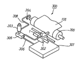
図1は本発明を適用したインクジェットプリンタの機構系の全体構成を示す概略構成図である。本例のインクジェットプリンタ300の機構系は一般的なものであり、記録紙105を搬送するための搬送手段の構成要素であるプラテンローラ300と、このプラテンローラ300に対峙しているインクジェットヘッド1と、このインクジェットヘッド1をプラテンローラ300の軸線方向である行方向(主走査方向)に往復移動させるキャリッジ302と、インクジェットヘッド1に対してインクチューブ306を介してインクを供給するインクタンク301を有している。
(Outline of mechanical system)
FIG. 1 is a schematic configuration diagram showing the overall configuration of a mechanism system of an ink jet printer to which the present invention is applied. The mechanism system of the
303はポンプであり、インクジェットヘッド1にインク吐出不良が発生した場合等において、キャップ304、廃インクチューブ308を介して、インクを吸引して廃インク溜め305に回収するために使用する。
A
(インクジェットヘッド)
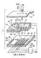
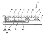
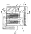
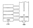
図2は本例のインクジェットヘッドの分解斜視図、図3は組み立てられたインクジェットヘッドの概略縦断面図、図4はその概略縦断面図であり、図5はその電極配置を示す説明図である。
(Inkjet head)
2 is an exploded perspective view of the ink jet head of this example, FIG. 3 is a schematic longitudinal sectional view of the assembled ink jet head, FIG. 4 is a schematic longitudinal sectional view thereof, and FIG. 5 is an explanatory view showing an electrode arrangement thereof. .
これらの図に示すように、インクジェットヘッド1は、インク液滴を基板の上面に設けたインクノズルから吐出させるフェイスインクジェットタイプの静電式インクジェットヘッドである。このインクジェットヘッド1は、キャビティプレート3を挟み、上側のノズルプレート2、下側にガラス基板4がそれぞれ積層された3層構造となっている。
As shown in these drawings, the
キャビティプレート3は例えばシリコン基板であり、当該プレートの表面には、底板が振動板5として機能する圧力室6を構成することになる凹部7と、凹部7の後部に設けられたインク供給口8を形成することになる細溝9と、各々の圧力室6にインクを供給するための共通インク室10を構成することになる凹部11とがエッチングによって形成されている。
The
これに加えて、大気に連通した大気圧室12を構成することになる凹部13が、最も端に位置している圧力室用の凹部7の隣接位置にエッチングによって形成されている。この大気圧室12の底板部分が外気圧変動に応じて変位する変位板16として機能する。本例では、この変位板16のコンプライアンスを、各振動板5のコンプライアンスの総和の約1万倍以上となるように設定している。
In addition to this, a
さらに、大気圧室12を外部に連通するための連通孔14を構成することになる細溝15も形成されている。キャビティプレート3の下面は鏡面研磨によって平滑化されている。
Furthermore, a
キャビティプレート3の上側に接合されるノズルプレート2は、キャビティプレート3と同様に例えばシリコン基板である。ノズルプレート2において、圧力室6の上面を規定している部分には各圧力室6に連通する複数のインクノズル21が形成されている。また、共通インク室10の上面を規定する部分には共通インク室10にインクを供給するインク供給孔22が形成されている。
The
ノズルプレート2をキャビティプレート3に接合することにより、上記の凹部7,11,13および細溝9,15が塞がれて、圧力室6、インク供給口8、共通インク室10、大気圧室12および連通孔14のそれぞれが区画形成される。
By joining the
なお、インク供給孔22は、接続パイプ23およびインクチューブ306(図1参照)を介してインクタンク301(図1参照)に接続される。インク供給孔22から供給されたインクは、各インク供給口8を経由して独立した各圧力室6に供給される。
The
キャビティプレート3の下側に接合されるガラス基板4は、シリコンと熱膨張率が近いホウ珪酸ガラス基板である。ガラス基板4において、各々の振動板5に対向する部分には密閉室としての振動室41を構成することになる凹部42が形成されている。各凹部42の底面には、各振動板5に対応する個別電極43が形成されている。個別電極43は、ITOからなるセグメント電極部44と端子部45を有している。
The
また、ガラス基板4における大気圧室12の底板部分である変位板16に対向する部分にも、凹部42と同一の深さの凹部46が形成されており、この凹部46は連通用凹部47を介して各凹部42に繋がっている。凹部46にもITOからなるダミー電極48が形成されている。
A
ガラス基板4をキャビティプレート3に接合することにより、各圧力室6の底面を規定している振動板5と個別電極43のセグメント電極部44は、非常に狭い隙間Gを隔てて対向する。この隙間Gはキャビティプレート3とガラス基板4の間に配置された封止剤20によって封止され、密閉状態の振動室41が形成される。また、大気圧室12の底板部分である変位板16によって凹部46が塞がれて、外気圧の変動による各振動室41の圧力を補償するための圧力補償室49が形成される。この圧力補償室49は連通用凹部47によって形成された連通部50を介して各振動室41に連通した状態になる。
By bonding the
振動板5は薄肉とされており、面外方向、すなわち、図3において上下方向に弾性変形可能となっている。この振動板5は、各圧力室側の共通電極として機能する。隙間Gを挟み、振動板5と、対応する各セグメント電極部44とによって、対向電極が形成されている。
The
振動板5と個別電極43との間には後述のヘッドドライバ220(図6参照)が接続されている。ヘッドドライバ220の一方の出力は各個別電極43の端子部45に接続され、他方の出力はキャビティプレート3に形成された共通電極端子26に接続されている。キャビティプレート自体は導電性をもつために、この共通電極端子26から振動板5に電圧を供給することができる。なお、より低い電気抵抗で振動板5に電圧を供給する必要がある場合には、例えば、キャビティプレート3の一方の面に金等の導電性材料の薄膜を蒸着やスパッタリングで形成すればよい。本例では、キャビティプレート3とガラス基板4の接続に陽極接合を用いているので、キャビティプレート3の流路形成面側に導電膜を形成してある。また、前述のダミー電極48も、陽極接合時に変位板16がガラス基板の側に貼りついてしまうことを防止するためのものである。
A head driver 220 (see FIG. 6) described later is connected between the
(圧力補償動作)
この構成のインクジェットヘッド1においては、ヘッドドライバ220からの駆動電圧が対向電極間に印加されると、対向電極間に充電された電荷による静電気力が発生し、振動板5はセグメント電極部44の側へ撓み、圧力室6の容積が増加する。次にヘッドドライバ220からの駆動電圧を解除して対向電極間の電荷を放電すると、振動板はその弾性復帰力によって復帰し、圧力室6の容積が急激に収縮する。この時に発生する内圧変動により、圧力室6に貯留されたインクの一部が、圧力室6に連通しているインクノズル21から記録紙に向かって吐出する。
(Pressure compensation operation)
In the
ここで、外気圧が変動した場合について説明する。例えば、平地から高地に移動した場合には外気圧が低下する。この場合、各振動室41の内圧が変動しないとすると、当該内圧は外気圧に比べて大幅に高くなる。この結果、圧力平衡状態を得るために、各振動室41の振動板5は図4において上方に撓み、各振動室41の容積を増加させることになる。
Here, a case where the external atmospheric pressure fluctuates will be described. For example, when it moves from a flat ground to a highland, the external atmospheric pressure decreases. In this case, if the internal pressure of each
しかしながら、本例では、各振動室41は連通部50を介して、圧力補償室49に連通している。この圧力補償室49は変位板16を挟み、大気側に連通した大気圧室12に面している。変位板16のコンプライアンスは各振動板5に比べて非常に大きい。よって、振動板5が変位する前に、当該変位板16が図4において上方に変位して圧力補償室49の容積が増加し、外気圧との圧力平衡状態が形成される。従って、各振動板5と個別電極43のギャップが外気圧の変動に関係なく常に一定の値に保持される。
However, in this example, each
以上のように、本例のインクジェットヘッド1においては、外気圧が変動しても、それが各振動板の振動特性に悪影響を及ぼすことが実質的に無い。よって、外気圧の変動にかかわりなく、常に安定したインク吐出特性を得ることができる。
As described above, in the
なお、本例のインクジェットヘッドにおいては、振動室41および圧力補償室49を平面方向に形成している。すなわち、キャビティプレート3に圧力室用の凹部7を形成する際、すなわち振動板5を形成する際に、同時に、振動板5の厚みとほぼ等しい変位板16を形成している。よって、圧力補償機能を備えたインクジェットヘッドの製造が容易である。また、変位板16は、ノズルプレート2によって覆われているので、この部分が破損することの無い様に確実に保護できるという利点もある。さらに、このような保護部分はノズルプレート2の一部を利用しているので、別途、保護プレート等を設ける場合に比べて製造が容易であるという利点もある。
In the ink jet head of this example, the
(制御系)
なお、図6は本例のインクジェットプリンタ300の制御系の概略構成図である。この制御系の中心をなす回路部分は例えば1チップマイクロコンピュータにより構成することができる。図を参照して本例の制御系の概要を簡単に説明すると、201はプリンタ制御回路であり、このプリンタ制御回路201には、アドレスバスおよびデータバスを含む内部バス202,203,204を介して、RAM205、ROM206およびキャラクタジェネレータROM(以降、CG−ROMという)207が接続されている。
(Control system)
FIG. 6 is a schematic configuration diagram of a control system of the
ROM206内には制御プログラムが格納されており、ここから呼び出されて起動する制御プログラムに基づき、インクジェットヘッド1の駆動制御動作が実行される。RAM205は駆動制御における作業領域として利用され、CG−ROM207には入力文字に対応したドットパターンが展開されている。
A control program is stored in the
210はヘッド駆動制御回路であり、内部バス209を介して接続されているプリンタ制御回路201の制御の下に、ヘッドドライバ220に対して駆動信号、クロック信号等を出力する。また、データバス211を介して印刷データDATAが供給される。
A head
ヘッドドライバ220は例えばTTLアレイから構成されており、入力される駆動信号に対応した駆動電圧パルスを生成して、これらを駆動対象となる個別電極43および共通電極端子26に印加して、対応するインクノズル21からインク液滴の吐出を行わせる。駆動電圧パルスを生成するために、ヘッドドライバ220には、接地電圧GND、駆動電圧Vn等が供給されている。これらの電圧は電源回路230の駆動電圧Vccから生成されるものである。
The
次に、プリンタ制御回路201には、内部バス231を介してキャリッジモータ駆動制御回路232が接続されている。キャリッジモータ駆動制御回路232は、モータドライバ233を介して、インクジェットヘッド1を担持しているキャリッジ302を往復移動させるためのキャリッジモータ(図示せず)を駆動して、図において矢印234で示す行方向にインクジェットヘッド1を移動させる。また、プリンタ制御回路201には、内部バス241を介して搬送モータ駆動制御回路242が接続されている。搬送モータ駆動制御回路242は、モータドライバ243を介して、搬送モータを駆動して、プラテンローラ300に沿って記録紙105を図の矢印244で示す搬送方向に搬送制御する。
Next, a carriage motor drive control circuit 232 is connected to the
[第2の実施例]
ここで、上記のインクジェットヘッド1における圧力補償用の変位板16は次に述べるように、平地における標準的な外気圧の下で平板状ではなく曲面状とすることもできる。
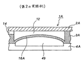
[Second Embodiment]
Here, the
図7は大気圧室12の側に凸状態に湾曲した曲面状の変位板16Aを備えたインクジェットヘッド1Aの部分断面図である。この変位板16A以外の部位は図2〜図5に示すインクジェットヘッド1と同一である。
FIG. 7 is a partial cross-sectional view of the
このような形状をした変位板16Aは次のように製造することができる。キャビティプレート3のエッチングに先立って、変位板16Aを形成する部分に、ボロンをドープすることにより、シリコンのボロンドープ層を形成しておく。振動板5を形成するためのエッチング時に同時に当該ボロンドープ層をエッチングして変位板16Aを形成する。
The
ボロンドープ層の部分は、ボロンが拡散されているので、他のシリコン部分に比べて膨張している。また、当該ボロンドープ層が形成されている部位の両側部分はボロンがドープされていないシリコン部分によって膨張が拘束された状態にある。従って、当該ボロンドープ層の部分に薄い変位板16Aを形成すると、当該変位板16Aは、全体として面外方向に凸状あるいは凹状に湾曲した曲面状になる。
The boron-doped layer portion is expanded as compared with other silicon portions because boron is diffused. In addition, both side portions of the portion where the boron doped layer is formed are in a state in which expansion is restricted by silicon portions not doped with boron. Therefore, when the
変位板16Aが形成されたキャビティプレート3の下側にはガラス基板4が陽極接合され、変位板16Aと、これに対峙するガラス基板の部分とによって密閉された圧力補償室49が区画形成される。変位板16Aの反対側は大気圧室12に面している。従って、変位板16Aは、図7に示すように、大気圧室12の側に凸の曲面状に撓む。
The
このように大気圧室12の側に凸状に撓んだ変位板16Aを備えたインクジェットヘッド1Aにおいては、外気圧が高い場合には、変位板16Aは圧力補償室49の側に押されて撓む。よって、平坦な変位板16の場合に比べて、外気圧が高い場合の気圧変動をより効果的に補償できる。
Thus, in the
しかしながら、このように大気圧側に凸の変位板16Aは、外気圧が圧力補償室49の内圧(当該圧力補償室49を封止したときの気圧)よりも低い場合には、より凸状態となる方向に撓む必要があるので、そのコンプライアンスが小さくなる。このために、充分な圧力補償機能を発揮できない場合が考えられる。
However, the
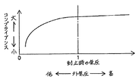
図8は、変位板16Aの外気圧に対するコンプライアンスの変動特性を定性的に示す特性曲線を示すグラフである。このグラフにおいて、横軸は外気圧を示し、縦軸はコンプライアンスを示している。このグラフから分かるように、圧力補償室49の封止時の気圧よりも外気圧が低下する程、変位板16Aのコンプライアンスは小さくなり、非線形状態で急激に低下する。すなわち、変位板16Aが撓みにくくなり、従って、圧力補償機能が急激に低下してしまう。
FIG. 8 is a graph showing a characteristic curve qualitatively showing the fluctuation characteristic of compliance with respect to the external pressure of the
外気圧が低い場合、例えば高地においても変位板16Aのコンプライアンスが充分に高くなるようにするためには、圧力補償室49を減圧封止することが望ましい。例えば、絶対圧で650hPa±50hPa程度の圧力状態で圧力補償室49を減圧封止することが望ましい。
When the outside air pressure is low, for example, in order to ensure that the compliance of the
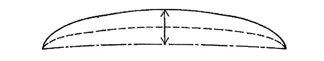
図9は減圧封止した場合の変位板16Aの挙動を示すための説明図である。この図において、実線は気密封止前の変位板16Aの状態を示し、点線は減圧封止を行った後の変位板16Aの状態を示し、一点鎖線は、外気圧が高い場合の変位板16Aの状態を示す。
FIG. 9 is an explanatory diagram for illustrating the behavior of the
このように、外気圧が高圧の場合においても、変位板16Aが、圧力補償室49の底面(ダミー電極48の表面)に当たって機能しなくなることがない。また、図8のグラフから分かるように、外気圧の変動に対して変位板16Aのコンプライアンスをほぼ線形関係に保持することができるので、外気圧の変動に伴う補償を確実に行うことが可能になる。
In this way, even when the external atmospheric pressure is high, the
[第3の実施例]
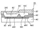
図10および図11は、本発明を適用したインクジェットヘッドの第3の実施例を示す概略断面図、および振動室と圧力補償室の配置関係を示す説明図である。本例のインクジェットヘッド1Bの基本的な構造は上記のインクジェットヘッド1,1Aと同様であり、キャビティプレート3Bを挟み、上下にそれぞれ、ノズルプレート2Bおよびガラス基板4Bが積層された構造となっている。
[Third embodiment]
10 and 11 are a schematic cross-sectional view showing a third embodiment of the ink jet head to which the present invention is applied, and an explanatory view showing the positional relationship between the vibration chamber and the pressure compensation chamber. The basic structure of the
ノズルプレート2Bにはインクノズル21Bが形成されている。ノズルプレート2Bとキャビティプレート3Bの間には、インクノズル21Bに連通している圧力室6Bと、各圧力室6Bに対してインク供給室8Bを介して連通している共通インク室10Bが区画形成されている。また、共通インク室10Bに隣接した位置には、大気圧室12Bが区画形成されており、この大気圧室12Bは大気連通孔14Bを介して大気に連通している。
大気圧室12Bの底面部分には薄い変位板16Bが形成されており、各圧力室6Bの底面部分にも振動板5Bが形成されている。キャビティプレート3Bの下面とガラス基板4Bの間には、振動板5Bを変位させるためのギャップを備えた振動室41Bと、変位板16Bを変位させるためのギャップを備えた圧力補償室49Bが区画形成されている。各振動室41Bに圧力補償室49Bが連通している。これら振動室41Bの底面にはITOからなる個別電極43Bが形成され、圧力補償室49Bの底面にもITOからなるダミー極48Bが形成されている。ここで、共通インク室10Bを形成しているノズルプレート2Bの部分は面外方向に変位可能な変位板10aとされている。この変位板10aは、各圧力室6B内での圧力変動が共通インク室10Bを介して隣接している圧力室6Bに伝搬するのを防止するためのものであり、圧力変動に応じて面外方向に弾性変位する。
A
本例のインクジェットヘッド1Bにおいても、圧力補償室49Bを区画している変位板16Bが外気圧の変動に応じて変位する。よって、各振動板5Bが外気圧の変動により変位することを防止して、安定したインク吐出特性を保持できる。
Also in the
なお、大気圧室12B、圧力補償室49Bを複数形成する構成を採用することもできる。図12には、2個の大気圧室と、これらに対応する2個の圧力補償室とを形成し、これに応じて、2つの変位板を配置した例を示してある。
A configuration in which a plurality of atmospheric pressure chambers 12B and
図13には、インクジェットヘッド1Bの改良例を示してある。このインクジェットヘッド1Cも、キャビティプレート3Cを挟み、上下にそれぞれ、ノズルプレート2Cおよびガラス基板4Cが積層された構造となっている。ノズルプレート2Cにはインクノズル21Cが形成されている。ノズルプレート2Cとキャビティプレート3Cの間には、インクノズル21Cが連通している圧力室6Cと、各圧力室6Cに対してインク供給室8Cを介して連通している共通インク室10Cが区画形成されている。
FIG. 13 shows an improved example of the
各圧力室6Cの底面部分には振動板5Cが形成されている。また、共通インク室10Cの底面部分には当該振動板5Cに比べて遥かにコンプライアンスが大きな変位板16Cが形成されている。キャビティプレート3Cの下面とガラス基板4Cの間には、振動板5Cを変位させるためのギャップを備えた振動室41Cと、変位板16Cを変位させるためのギャップを備えた圧力補償室49Cが区画形成されている。各振動室41Cに圧力補償室49Cが連通している。これら振動室41Cの底面にはITOからなる個別電極43Cが形成され、圧力補償室49Cの底面にもITOからなるダミー電極48Cが形成されている。
A
本例のインクジェットヘッド1Cにおいては、共通インク室10Cの底面部分に変位板16Cを形成してある。従って、この変位板16Cは、上記のインクジェットヘッド1Bにおける変位板16Bと変位板10aの双方の機能を兼ね備えている。すなわち、この変位板16Cは、各圧力室6C内での圧力変動が共通インク室10Cを介して隣接している圧力室6Cに伝搬するのを防止する。また、外気圧の変動に応じて変位して、各振動板5Cが外気圧の変動により変位することを防止して、安定したインク吐出特性を保持している。
In the
本例のインクジェットヘッド1Cは、前述のインクジェットヘッド1Bに比べて、小型コンパクトに構成できる。すなわち、大気圧室を別途設ける必要がなく、また、単一の変位板16Cによって、外気初の変動補償および共通インク室内の内圧変動を吸収しているからである。
The
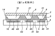
[第4の実施例]
図14(A)および図14(B)は,本発明を適用したインクジェットヘッドの第4の実施例を示す部分断面図および、その振動室と圧力補償室の配置関係を示す説明図である。このインクジェットヘッド1Dも、キャビティプレート3Dを挟み、上下にそれぞれ、ノズルプレート2Dおよびガラス基板4Dが積層された構造となっている。ノズルプレート2Dにはインクノズル21Dが形成されている。ノズルプレート2Dとキャビティプレート3Dの間には、インクノズル21Dが連通している圧力室6Dと、各圧力室6Dに対してインク供給室8Dを介して連通している共通インク室10Dと、大気に連通した大気圧室12Dとが区画形成されている。
[Fourth embodiment]
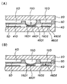
14A and 14B are a partial cross-sectional view showing a fourth embodiment of an ink jet head to which the present invention is applied, and an explanatory view showing the positional relationship between the vibration chamber and the pressure compensation chamber. The
各圧力室6Dの底面部分には振動板5Dが形成されている。また、共通インク室10Dの底面部分には第1の変位板16D1が形成されている。同様に大気圧室12Dの底面部分にも第2の変位板16D2が形成されている。
A
キャビティプレート3Dの下面とガラス基板4Dの間には、振動板5Cを変位させるためのギャップを備えた振動室41Dと、第1の変位板16D1を変位させるためのギャップを備えた第1の圧力補償室49D1と、第2の変位板16D2を変位させるためのギャップを備えた第2の圧力補償室49D2が区画形成されている。各振動室41Dに第1の圧力補償室49D1が連通しており、この第1の圧力補償室49D1には第2の圧力補償室49D2が連通している。
Between the lower surface of the
各振動室41Dの底面にはITOからなる個別電極43Dが形成され、第1の圧力補償室49D1、第2の圧力補償室49D2の底面にもそれぞれITOからなる電極48D1,48D2が形成されている。
An
図15(A)に示すように、第1の変位板16D1と電極48D1の間に電圧を印加すると、静電吸引力が発生して第1の変位板16D1が電極側に吸引されて撓む。この結果、第1の圧力補償室49D1の容積が減少して、連通している振動室41Dの内圧を高める。電圧の印加を停止すると、第1の変位板16D1が弾性復帰するので、振動室41Dの内圧も元に戻る。
As shown in FIG. 15A, when a voltage is applied between the first displacement plate 16D1 and the electrode 48D1, an electrostatic attraction force is generated, and the first displacement plate 16D1 is attracted to the electrode side and bent. . As a result, the volume of the first pressure compensation chamber 49D1 decreases, and the internal pressure of the communicating
例えば、周囲の気圧が所定の値である場合に、図15(B)に示すように、第1の変位板16D1と電極48D1の間に電圧を印加して第1の変位板16D1を電極48D1に吸引しておく。外気圧が低くなった場合には、印加電圧を低下させるか、あるいは電圧印加を停止すると、各振動室41Dの内圧が低下するので、外気圧との圧力差が小さくなる。よって、振動板5Dの振動特性を一定に保持して、インクの吐出特性の変化を抑制できる。
For example, when the ambient atmospheric pressure is a predetermined value, as shown in FIG. 15B, a voltage is applied between the first displacement plate 16D1 and the electrode 48D1 to connect the first displacement plate 16D1 to the electrode 48D1. Keep it aspirated. When the external air pressure becomes low, when the applied voltage is lowered or the voltage application is stopped, the internal pressure of each
一方、外気圧が高くなった場合には、印加電圧を高くすると、第1の変位板16D1の撓みが大きくなり、振動室41Dの圧力を上昇させることができるので、外気圧との圧力差を小さくでき、この場合においてもインクの吐出特性の変動を抑制できる。
On the other hand, when the external air pressure becomes high, if the applied voltage is increased, the deflection of the first displacement plate 16D1 increases, and the pressure in the
ここで、外気圧の変化量が大きい場合には次のように第2の圧力補償室12D2の容積変化を利用すればよい。すなわち、外気圧が所定の値である場合に、図15(A)に示すように、第1の変位板16D1と電極48D1の間に電圧を印加し、第1の変位板16D1を電極48D1に吸引した状態に保持しておく。外気圧が高くなった場合には、第2の変位板16D2と電極48D2の間に電圧を印加して第2の変位板16D2も撓ませる。この結果、第2の圧力補償室12D2の容積も減少するので、各振動室41Dの圧力を外気圧の上昇に合わせて大幅に増加させることができる。これにより、大幅に上昇した外気圧と各振動室の内圧との圧力差を減少あるいは無くすことができる。
Here, when the amount of change in the external air pressure is large, the volume change in the second pressure compensation chamber 12D2 may be used as follows. That is, when the external air pressure is a predetermined value, as shown in FIG. 15A, a voltage is applied between the first displacement plate 16D1 and the electrode 48D1, and the first displacement plate 16D1 is applied to the electrode 48D1. Keep in aspirated state. When the outside air pressure becomes high, a voltage is applied between the second displacement plate 16D2 and the electrode 48D2 to bend the second displacement plate 16D2. As a result, the volume of the second pressure compensation chamber 12D2 is also reduced, so that the pressure in each
逆に、外気圧が低下した場合には、電圧印加を停止して、第1の変位板16D1を元の状態に復帰させることにより、第1の圧力補償室49D1の容積を増加させる。この結果、各振動室41Dの内圧が低下して、外気圧との圧力差が減少あるいは無くなる。
Conversely, when the external air pressure decreases, the voltage application is stopped and the first displacement plate 16D1 is returned to the original state, thereby increasing the volume of the first pressure compensation chamber 49D1. As a result, the internal pressure of each
このような第1の圧力補償室12D1および第2の圧力補償室12D2の容積を増減するための各電極48D1,48D2に対する電圧印加制御は、次のような制御機構によって行うことができる。 Such voltage application control to the electrodes 48D1 and 48D2 for increasing and decreasing the volumes of the first pressure compensation chamber 12D1 and the second pressure compensation chamber 12D2 can be performed by the following control mechanism.
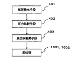
すなわち、図16に示すように、気圧検出手段401により外気圧を検出し、圧力比較手段402により設定気圧と検出された外気圧を比較し、比較結果に基づき、変位板駆動手段403によって各第1の変位板16D1、第2の変位板16D2を変位させればよい。 That is, as shown in FIG. 16, the atmospheric pressure detection means 401 detects the external atmospheric pressure, the pressure comparison means 402 compares the set atmospheric pressure with the detected external atmospheric pressure, and the displacement plate driving means 403 makes each of the first pressures based on the comparison result. The first displacement plate 16D1 and the second displacement plate 16D2 may be displaced.
なお、気圧検出手段としては、例えば静電容量式の気圧センサ、圧電式の気圧センサ等の各種のセンサを用いることができる。また、気圧検出手段の取り付け位置は、インクジェットヘッド1Dの近傍に限定されるものではなく、同様な気圧測定ができる位置ならばいずれの位置でもよい。
また、外気圧は、変位板と電極間の電気容量を検出することによって算出することが可能である。
As the atmospheric pressure detecting means, various sensors such as a capacitance type atmospheric pressure sensor and a piezoelectric type atmospheric pressure sensor can be used. Further, the attachment position of the atmospheric pressure detection means is not limited to the vicinity of the
The external air pressure can be calculated by detecting the electric capacity between the displacement plate and the electrode.
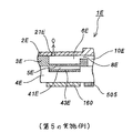
[第5の実施例]
図17は本発明を適用したインクジェットヘッドの第5の実施例の主要部分を示す部分構成図である。本例のインクジェットヘッド1Eの基本的な構造は上記の各例における場合と同様であり、キャビティプレート3Eを挟み、上下にそれぞれ、ノズルプレート2Eおよびガラス基板4Eが積層された構造となっている。ノズルプレート2Eにはインクノズル21Eが形成されている。ノズルプレート2Eとキャビティプレート3Eの間には、インクノズル21Eが連通している圧力室6Eと、各圧力室6Eに対してインク供給室8Eを介して連通している共通インク室10Eとが区画形成されている。各圧力室6Eの底面部分には振動板5Eが形成されている。
[Fifth embodiment]
FIG. 17 is a partial configuration diagram showing the main part of a fifth embodiment of an ink jet head to which the present invention is applied. The basic structure of the
キャビティプレート3Eの下面とガラス基板4Eの間には、振動板5Eを変位させるためのギャップを備えた振動室41Eが区画形成されている。各振動室41Eの底面にはITOからなる個別電極43Eが形成されている。
A
本例の特徴は、圧力補償手段として、変位板によって容積が変動する圧力補償室を設ける代わりに、熱制御体160を用いて、振動室41Eの封入気体を加熱冷却することにより、当該振動室41Eの内圧を増減させ、これにより、外気圧との圧力差を低減あるいは解消している点にある。
The feature of this example is that instead of providing a pressure compensation chamber whose volume varies with the displacement plate as a pressure compensation means, the
ボイル・シャルルの法則で周知であるが、気圧は温度によっても制御可能である。例えば、外気圧が高くなった場合には、熱制御体160を発熱させ、ガラス基板4Eにおける振動室形成部分を加熱すると、振動室内の気体が温められて膨張しようとする。しかし、振動室41Eは密閉状態にあるので内圧が高まり、外気圧との圧力差が緩和される。
As is well known by Boyle-Charles' law, the atmospheric pressure can also be controlled by temperature. For example, when the external air pressure becomes high, the
逆に、外気圧が低下した場合には、熱制御体160により吸熱あるいは冷却動作を行い、ガラス基板4Eを冷却し、振動室内の気体を冷却して、その内圧を低下させる。これによって、外気圧との圧力差を解消できる。
On the contrary, when the external air pressure decreases, the
熱制御体としては、例えば、窒化タンタル薄膜にように発熱体であってもよい。又は、ペルチエ素子のように吸熱も行えるものでもよい。 The heat control body may be a heating element such as a tantalum nitride thin film. Or what can also absorb heat like a Peltier element may be used.
図18は熱制御体の駆動制御機構の概略図である。この図に示すように、気圧検出手段501により外気圧を検出する。検出された外気圧を、気圧・温度換算手段502において、振動室41Eの内部温度に換算する。換算された温度を、温度比較手段503において、予め設定されている目標温度と比較する。熱制御体駆動手段504では、比較結果に基づき、振動室内の温度が目標温度となるように熱制御体160を駆動する。
FIG. 18 is a schematic diagram of the drive control mechanism of the thermal control body. As shown in this figure, the atmospheric pressure is detected by the atmospheric pressure detection means 501. The detected external atmospheric pressure is converted into the internal temperature of the
なお、ガラス基板4Eに温度検出手段505を取り付け(図17参照)、この検出値を目標温度と比較することにより、より正確な温度管理を実行することができる。
In addition, more accurate temperature management can be performed by attaching the temperature detection means 505 to the
また、気圧の検出は、気圧センサ等をインクジェットプリンタに搭載する代わりに、振動室41Eにおける振動板5Eと個別電極43Eの間の電気容量に基づき算出することもできる。
Further, the detection of the atmospheric pressure can be calculated based on the electric capacity between the diaphragm 5E and the
この場合には、図19に示すように、振動板と電極間の電気容量を、電気容量検出手段601によって検出し、検出された電気容量を、比較手段602により予め定めた目標値と比較し、この比較結果に基づき、熱制御体駆動手段603によって熱発熱体を駆動制御すればよい。
In this case, as shown in FIG. 19, the capacitance between the diaphragm and the electrode is detected by the capacitance detecting means 601, and the detected capacitance is compared with a predetermined target value by the comparing
[その他の実施の形態]
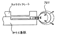
なお、前述の実施例においては、圧力補償室の一部に変位板を形成し、外気圧変動に応じて当該変位板が変位することにより圧力補償室の容積が増減するようになっている。この代わりに、図20に示すように、圧力補償室701の全体を伸縮性の素材から形成し、外気圧変動に応じて全体を膨張および縮小させるようにしてもよい。
[Other embodiments]
In the above-described embodiment, a displacement plate is formed in a part of the pressure compensation chamber, and the displacement plate is displaced in accordance with fluctuations in the external atmospheric pressure, whereby the volume of the pressure compensation chamber is increased or decreased. Instead, as shown in FIG. 20, the entire
以上説明したように、本発明の静電アクチュエータは、振動板によって仕切られている振動室の内圧と外気圧の圧力差を減少あるいは無くすための圧力補償手段を備えているため、振動板の振動特性が外気圧の変動によって変化することが無い。従って、本発明を適用した液滴吐出装置は、外気圧の変動にかかわりなく、常に安定した液滴の吐出動作を行うことのできる。例えば、本発明を用いたインクジェットプリンタは、高地、低地等の使用場所に左右されることなく、常に高品位の画像形成を行うことができる。 As described above, the electrostatic actuator of the present invention includes the pressure compensation means for reducing or eliminating the pressure difference between the internal pressure and the external pressure of the vibration chamber partitioned by the vibration plate. The characteristics do not change due to fluctuations in the external pressure. Therefore, the droplet discharge device to which the present invention is applied can always perform a stable droplet discharge operation regardless of fluctuations in the external pressure. For example, an inkjet printer using the present invention can always perform high-quality image formation without being affected by places of use such as highlands and lowlands.
1,1A〜1E…インクジェットヘッド、2,2B〜2E…ノズルプレート、3,3B〜3E…キャビティプレート、4,4B〜4E…ガラス基板、5,5B〜5E…振動板、6,6B〜6E…圧力室、7,11,13,42,46…凹部、8…インク供給口、8B〜8E…インク供給室、9,15…細溝、10,10B〜10E…共通インク室、10a,16,16A〜16C…変位板、12,12B,12D…大気圧室、12D1,49D1…第1の圧力補償室、12D2,49D2…第2の圧力補償室、14…連通孔、14B…大気連通孔、16D1…第1の変位板、16D2…第2の変位板、20…封止剤、21,21B〜21E…インクノズル、22…インク供給孔、23…接続パイプ、26…共通電極端子、41…密閉室としての振動室、41B〜41E…振動室、43,43B〜43E…個別電極、44…セグメント電極部、45…端子部、47…連通用凹部、48,48C…ダミー電極、48B…ダミー極、48D1,48D2…電極、49,49B,49C,701…圧力補償室、50…連通部、105…記録紙、160…熱制御体、201…プリンタ制御回路、202〜204,209,231,241…内部バス、205…RAM、206…ROM、207…CG−ROM、211…データバス、220…ヘッドドライバ、230…電源回路、232…キャリッジモータ駆動制御回路、233,243…モータドライバ、234,244…矢印、242…搬送モータ駆動制御回路、300…インクジェットプリンタ、301…インクタンク、302…キャリッジ、304…キャップ、306…インクチューブ、308…廃インクチューブ、401,501…気圧検出手段、402…圧力比較手段、403…変位板駆動手段、502…気圧・温度換算手段、503…温度比較手段、504,603…熱制御体駆動手段、505…温度検出手段、601…電気容量検出手段、602…比較手段、DATA…印刷データ、G…隙間、GND…接地電圧、ROM…キャラクタジェネレータ、Vcc,Vn…駆動電圧。
1, 1A to 1E: inkjet head, 2, 2B to 2E ... nozzle plate, 3, 3B to 3E ... cavity plate, 4, 4B to 4E ... glass substrate, 5, 5B to 5E ... diaphragm, 6, 6B to 6E ... Pressure chamber, 7, 11, 13, 42, 46 ... Recess, 8 ... Ink supply port, 8B-8E ... Ink supply chamber, 9, 15 ... Narrow groove, 10, 10B-10E ... Common ink chamber, 10a, 16 , 16A to 16C ... displacement plate, 12, 12B, 12D ... atmospheric pressure chamber, 12D1, 49D1 ... first pressure compensation chamber, 12D2, 49D2 ... second pressure compensation chamber, 14 ... communication hole, 14B ... atmospheric communication hole , 16D1 ... first displacement plate, 16D2 ... second displacement plate, 20 ... sealant, 21, 21B to 21E ... ink nozzle, 22 ... ink supply hole, 23 ... connection pipe, 26 ... common electrode terminal, 41 ... as a sealed room Vibration chamber, 41B to 41E ... Vibration chamber, 43, 43B to 43E ... Individual electrode, 44 ... Segment electrode portion, 45 ... Terminal portion, 47 ... Communication recess, 48, 48C ... Dummy electrode, 48B ... Dummy electrode, 48D1, 48D2 ... Electrodes, 49, 49B, 49C, 701 ... Pressure compensation chamber, 50 ... Communication section, 105 ... Recording paper, 160 ... Thermal control body, 201 ... Printer control circuit, 202-204, 209, 231, 241 ...
Claims (1)
前記振動室に連通すると共に外気圧に応じて容積を増減し前記振動室の内圧と外気圧の圧力差を低減する圧力補償室を有し、
前記圧力補償室の一部が、外気圧に応じて変位可能な変位板により構成され、
前記電極板上には前記変位板に対峙して電極が形成され、
前記変位板は、外気圧に応じて前記変位板と前記電極間に印加された電圧で変位するよう構成されていることを特徴とする静電式液体噴射装置。 A nozzle for discharging liquid droplets, a pressure chamber in which the nozzle communicates and holds a liquid, a diaphragm that constitutes a part of the pressure chamber and can vibrate, and is opposed to the diaphragm An electrode plate, and a vibration chamber hermetically formed between the electrode plate and the diaphragm, and by applying a voltage between the diaphragm and the electrode plate, the diaphragm is vibrated by electrostatic force, In the electrostatic liquid ejecting apparatus that gives a pressure fluctuation for discharging the liquid in the pressure chamber,
A pressure compensation chamber that communicates with the vibration chamber and increases or decreases the volume according to the external pressure to reduce a pressure difference between the internal pressure and the external pressure of the vibration chamber;
A part of the pressure compensation chamber is constituted by a displacement plate that can be displaced according to the external pressure,
An electrode is formed on the electrode plate to face the displacement plate,
The electrostatic liquid ejecting apparatus according to claim 1, wherein the displacement plate is configured to be displaced by a voltage applied between the displacement plate and the electrode in accordance with an external air pressure.
Priority Applications (1)
| Application Number | Priority Date | Filing Date | Title |
|---|---|---|---|
| JP2008283240A JP4321663B2 (en) | 1998-03-18 | 2008-11-04 | Electrostatic liquid ejector |
Applications Claiming Priority (2)
| Application Number | Priority Date | Filing Date | Title |
|---|---|---|---|
| JP6910598 | 1998-03-18 | ||
| JP2008283240A JP4321663B2 (en) | 1998-03-18 | 2008-11-04 | Electrostatic liquid ejector |
Related Parent Applications (1)
| Application Number | Title | Priority Date | Filing Date |
|---|---|---|---|
| JP54685999A Division JP4300591B2 (en) | 1998-03-18 | 1999-03-17 | Electrostatic actuator and liquid ejecting apparatus using the same |
Publications (2)
| Publication Number | Publication Date |
|---|---|
| JP2009035009A JP2009035009A (en) | 2009-02-19 |
| JP4321663B2 true JP4321663B2 (en) | 2009-08-26 |
Family
ID=13393026
Family Applications (8)
| Application Number | Title | Priority Date | Filing Date |
|---|---|---|---|
| JP54685999A Expired - Fee Related JP4300591B2 (en) | 1998-03-18 | 1999-03-17 | Electrostatic actuator and liquid ejecting apparatus using the same |
| JP2008283238A Expired - Fee Related JP4380777B2 (en) | 1998-03-18 | 2008-11-04 | Electrostatic liquid ejecting apparatus and electrostatic actuator manufacturing method |
| JP2008283240A Expired - Fee Related JP4321663B2 (en) | 1998-03-18 | 2008-11-04 | Electrostatic liquid ejector |
| JP2008283241A Expired - Fee Related JP4321664B2 (en) | 1998-03-18 | 2008-11-04 | Electrostatic liquid ejecting apparatus and electrostatic actuator |
| JP2008283239A Expired - Fee Related JP4321662B2 (en) | 1998-03-18 | 2008-11-04 | Electrostatic liquid ejector |
| JP2008283237A Expired - Fee Related JP4321661B2 (en) | 1998-03-18 | 2008-11-04 | Electrostatic liquid ejector |
| JP2009161552A Expired - Fee Related JP4380793B2 (en) | 1998-03-18 | 2009-07-08 | Liquid ejecting apparatus and actuator |
| JP2009180363A Expired - Fee Related JP4442715B2 (en) | 1998-03-18 | 2009-08-03 | Actuator |
Family Applications Before (2)
| Application Number | Title | Priority Date | Filing Date |
|---|---|---|---|
| JP54685999A Expired - Fee Related JP4300591B2 (en) | 1998-03-18 | 1999-03-17 | Electrostatic actuator and liquid ejecting apparatus using the same |
| JP2008283238A Expired - Fee Related JP4380777B2 (en) | 1998-03-18 | 2008-11-04 | Electrostatic liquid ejecting apparatus and electrostatic actuator manufacturing method |
Family Applications After (5)
| Application Number | Title | Priority Date | Filing Date |
|---|---|---|---|
| JP2008283241A Expired - Fee Related JP4321664B2 (en) | 1998-03-18 | 2008-11-04 | Electrostatic liquid ejecting apparatus and electrostatic actuator |
| JP2008283239A Expired - Fee Related JP4321662B2 (en) | 1998-03-18 | 2008-11-04 | Electrostatic liquid ejector |
| JP2008283237A Expired - Fee Related JP4321661B2 (en) | 1998-03-18 | 2008-11-04 | Electrostatic liquid ejector |
| JP2009161552A Expired - Fee Related JP4380793B2 (en) | 1998-03-18 | 2009-07-08 | Liquid ejecting apparatus and actuator |
| JP2009180363A Expired - Fee Related JP4442715B2 (en) | 1998-03-18 | 2009-08-03 | Actuator |
Country Status (5)
| Country | Link |
|---|---|
| US (2) | US6450625B1 (en) |
| EP (1) | EP0985533B1 (en) |
| JP (8) | JP4300591B2 (en) |
| DE (1) | DE69936122T2 (en) |
| WO (1) | WO1999047357A1 (en) |
Families Citing this family (26)
| Publication number | Priority date | Publication date | Assignee | Title |
|---|---|---|---|---|
| US20040099061A1 (en) * | 1997-12-22 | 2004-05-27 | Mks Instruments | Pressure sensor for detecting small pressure differences and low pressures |
| WO1999057144A2 (en) * | 1998-05-05 | 1999-11-11 | Incyte Pharmaceuticals, Inc. | Human transcriptional regulator molecules |
| JP3371331B2 (en) | 1998-12-14 | 2003-01-27 | セイコーエプソン株式会社 | Ink jet recording head and method of manufacturing the same |
| JP2002086718A (en) * | 2000-09-11 | 2002-03-26 | Ricoh Co Ltd | INK JET PRINT HEAD, METHOD OF MANUFACTURING THE INK JET PRINT HEAD, AND INK JET PRINTING APPARATUS HAVING THE INK JET PRINT HEAD |
| US6409311B1 (en) * | 2000-11-24 | 2002-06-25 | Xerox Corporation | Bi-directional fluid ejection systems and methods |
| AUPR245401A0 (en) * | 2001-01-10 | 2001-02-01 | Silverbrook Research Pty Ltd | An apparatus (WSM07) |
| EP1506092A4 (en) * | 2002-05-20 | 2007-05-09 | Ricoh Kk | Electrostatic actuator and liquid droplet ejecting head having stable operation characteristics against environmental changes |
| JP3794431B2 (en) * | 2003-02-28 | 2006-07-05 | セイコーエプソン株式会社 | Droplet ejection device and ejection abnormality detection / judgment method of droplet ejection head |
| JP3867794B2 (en) | 2003-04-16 | 2007-01-10 | セイコーエプソン株式会社 | Droplet ejection device, ink jet printer, and head abnormality detection / judgment method |
| JP3867793B2 (en) | 2003-03-28 | 2007-01-10 | セイコーエプソン株式会社 | Droplet ejection apparatus, inkjet printer, and ejection abnormality detection method for droplet ejection head |
| JP3867788B2 (en) | 2003-03-12 | 2007-01-10 | セイコーエプソン株式会社 | Droplet discharge device and inkjet printer |
| CN1286645C (en) * | 2003-02-28 | 2006-11-29 | 精工爱普生株式会社 | Liquid droplet discharge device and liquid droplet discharge head discharge abnormality detection and judgment method |
| JP3867791B2 (en) | 2003-03-27 | 2007-01-10 | セイコーエプソン株式会社 | Droplet ejection device and inkjet printer |
| US7232199B2 (en) | 2003-03-28 | 2007-06-19 | Seiko Epson Corporation | Droplet ejection apparatus and method of detecting and judging ejection failure in droplet ejection heads |
| US6927475B2 (en) * | 2003-11-19 | 2005-08-09 | Taiwan Semiconductor Manufacturing Co., Ltd. | Power generator and method for forming same |
| JP2005205721A (en) * | 2004-01-22 | 2005-08-04 | Sony Corp | Liquid discharge head and liquid discharge apparatus |
| US7334871B2 (en) | 2004-03-26 | 2008-02-26 | Hewlett-Packard Development Company, L.P. | Fluid-ejection device and methods of forming same |
| TWI308886B (en) * | 2004-06-30 | 2009-04-21 | Ind Tech Res Inst | Inkjet printhead and process for producing the same |
| US7513416B1 (en) * | 2004-07-29 | 2009-04-07 | Diebold Self-Service Systems | Cash dispensing automated banking machine deposit printing system and method |
| US20080062224A1 (en) * | 2004-09-28 | 2008-03-13 | Industrial Technology Research Institute | Inkjet printhead |
| US7201057B2 (en) * | 2004-09-30 | 2007-04-10 | Mks Instruments, Inc. | High-temperature reduced size manometer |
| US7141447B2 (en) * | 2004-10-07 | 2006-11-28 | Mks Instruments, Inc. | Method of forming a seal between a housing and a diaphragm of a capacitance sensor |
| US7137301B2 (en) * | 2004-10-07 | 2006-11-21 | Mks Instruments, Inc. | Method and apparatus for forming a reference pressure within a chamber of a capacitance sensor |
| US7571992B2 (en) * | 2005-07-01 | 2009-08-11 | Xerox Corporation | Pressure compensation structure for microelectromechanical systems |
| US9016835B1 (en) * | 2013-11-08 | 2015-04-28 | Xerox Corporation | MEMS actuator pressure compensation structure for decreasing humidity |
| JP6954335B2 (en) * | 2019-10-02 | 2021-10-27 | セイコーエプソン株式会社 | Information processing device, learning device and information processing method |
Family Cites Families (14)
| Publication number | Priority date | Publication date | Assignee | Title |
|---|---|---|---|---|
| JPH04284255A (en) | 1991-03-13 | 1992-10-08 | Canon Inc | liquid jet recording device |
| JP3175316B2 (en) | 1992-08-03 | 2001-06-11 | セイコーエプソン株式会社 | Inkjet head and recording device |
| JPH07285221A (en) * | 1994-04-19 | 1995-10-31 | Sharp Corp | Inkjet head |
| US6371598B1 (en) * | 1994-04-20 | 2002-04-16 | Seiko Epson Corporation | Ink jet recording apparatus, and an ink jet head |
| US6234607B1 (en) * | 1995-04-20 | 2001-05-22 | Seiko Epson Corporation | Ink jet head and control method for reduced residual vibration |
| JPH09300636A (en) * | 1996-03-13 | 1997-11-25 | Oki Data:Kk | Adjustment of ink jet head |
| JPH09314837A (en) * | 1996-03-26 | 1997-12-09 | Seiko Epson Corp | Inkjet head, printing apparatus using the same, and control method thereof |
| JPH1016210A (en) * | 1996-07-05 | 1998-01-20 | Fuji Xerox Co Ltd | Ink jet recorder |
| JPH1044407A (en) * | 1996-08-02 | 1998-02-17 | Ricoh Co Ltd | Method of manufacturing inkjet head |
| US6371599B1 (en) * | 1998-04-27 | 2002-04-16 | Minolta Co., Ltd. | Ink jet recording apparatus and drive unit and method for ink jet head |
| US6361154B1 (en) * | 1998-09-03 | 2002-03-26 | Matsushita Electric Industrial Co., Ltd. | Ink-jet head with piezoelectric actuator |
| RU2147522C1 (en) * | 1998-11-03 | 2000-04-20 | Самсунг Электроникс Ко., Лтд. | Microinjection apparatus |
| KR20010045305A (en) * | 1999-11-04 | 2001-06-05 | 윤종용 | Thermal-compress type ink jetting apparatus |
| US6568794B2 (en) * | 2000-08-30 | 2003-05-27 | Ricoh Company, Ltd. | Ink-jet head, method of producing the same, and ink-jet printing system including the same |
-
1999
- 1999-03-17 WO PCT/JP1999/001341 patent/WO1999047357A1/en not_active Ceased
- 1999-03-17 US US09/424,163 patent/US6450625B1/en not_active Expired - Lifetime
- 1999-03-17 EP EP99909216A patent/EP0985533B1/en not_active Expired - Lifetime
- 1999-03-17 DE DE69936122T patent/DE69936122T2/en not_active Expired - Lifetime
- 1999-03-17 JP JP54685999A patent/JP4300591B2/en not_active Expired - Fee Related
-
2002
- 2002-08-08 US US10/215,229 patent/US6799834B2/en not_active Expired - Lifetime
-
2008
- 2008-11-04 JP JP2008283238A patent/JP4380777B2/en not_active Expired - Fee Related
- 2008-11-04 JP JP2008283240A patent/JP4321663B2/en not_active Expired - Fee Related
- 2008-11-04 JP JP2008283241A patent/JP4321664B2/en not_active Expired - Fee Related
- 2008-11-04 JP JP2008283239A patent/JP4321662B2/en not_active Expired - Fee Related
- 2008-11-04 JP JP2008283237A patent/JP4321661B2/en not_active Expired - Fee Related
-
2009
- 2009-07-08 JP JP2009161552A patent/JP4380793B2/en not_active Expired - Fee Related
- 2009-08-03 JP JP2009180363A patent/JP4442715B2/en not_active Expired - Fee Related
Also Published As
| Publication number | Publication date |
|---|---|
| EP0985533A4 (en) | 2001-03-21 |
| JP2009035008A (en) | 2009-02-19 |
| US6799834B2 (en) | 2004-10-05 |
| JP2009061784A (en) | 2009-03-26 |
| JP4321664B2 (en) | 2009-08-26 |
| JP2009023360A (en) | 2009-02-05 |
| JP4380777B2 (en) | 2009-12-09 |
| EP0985533B1 (en) | 2007-05-23 |
| DE69936122D1 (en) | 2007-07-05 |
| JP2009255582A (en) | 2009-11-05 |
| EP0985533A1 (en) | 2000-03-15 |
| JP2009023359A (en) | 2009-02-05 |
| JP4300591B2 (en) | 2009-07-22 |
| US6450625B1 (en) | 2002-09-17 |
| JP4380793B2 (en) | 2009-12-09 |
| JP4442715B2 (en) | 2010-03-31 |
| JP2009220586A (en) | 2009-10-01 |
| JP4321662B2 (en) | 2009-08-26 |
| JP4321661B2 (en) | 2009-08-26 |
| WO1999047357A1 (en) | 1999-09-23 |
| JP2009035009A (en) | 2009-02-19 |
| DE69936122T2 (en) | 2008-01-17 |
| US20030003618A1 (en) | 2003-01-02 |
Similar Documents
| Publication | Publication Date | Title |
|---|---|---|
| JP4321663B2 (en) | Electrostatic liquid ejector | |
| JPWO1999047357A1 (en) | Electrostatic actuator, manufacturing method thereof, and liquid ejection device using the same | |
| JPH10305578A (en) | Ink jet recording head | |
| US6767084B2 (en) | Ink-jet recording head and ink-jet recording apparatus | |
| CN102189799B (en) | Liquid ejecting head and liquid ejecting apparatus | |
| JPS63151459A (en) | Liquid jet recording head | |
| JP5854191B2 (en) | Liquid ejecting head control method, control apparatus, and liquid ejecting apparatus | |
| JP2001300421A (en) | Electrostatic actuator and liquid ejecting apparatus using the same | |
| JP2002086713A (en) | On-demand type inkjet print head | |
| JP2004268397A (en) | Manufacturing method and joining apparatus for liquid jet head | |
| JPH04263952A (en) | Ink jet recording head | |
| JP2000071449A (en) | Ink jet head and ink jet recording apparatus | |
| JP3988284B2 (en) | Ink jet head and recording apparatus | |
| JP2002046265A (en) | Driving method of inkjet head | |
| JP3546878B2 (en) | Ink jet recording head | |
| JP4760630B2 (en) | Liquid droplet ejection head, liquid droplet ejection head driving method, and liquid droplet ejection apparatus | |
| JP2001010052A (en) | Electrostatic actuator and inkjet head | |
| JP2008260195A (en) | Electrostatic actuator, droplet discharge head, droplet discharge device, and method for manufacturing electrostatic actuator | |
| JP2000326508A (en) | Ink jet head and method of manufacturing the same | |
| JP2002046279A (en) | Droplet ejection head and microactuator | |
| JP2000168079A (en) | Electrostatic actuator and inkjet head | |
| JP2008080742A (en) | Liquid ejecting head and liquid ejecting apparatus | |
| JPH10166571A (en) | Ink jet recording head | |
| JP2003094637A (en) | Droplet ejection head and electrostatic actuator | |
| JP2000071452A (en) | Inkjet head |
Legal Events
| Date | Code | Title | Description |
|---|---|---|---|
| TRDD | Decision of grant or rejection written | ||
| A01 | Written decision to grant a patent or to grant a registration (utility model) |
Free format text: JAPANESE INTERMEDIATE CODE: A01 Effective date: 20090512 |
|
| A01 | Written decision to grant a patent or to grant a registration (utility model) |
Free format text: JAPANESE INTERMEDIATE CODE: A01 |
|
| A61 | First payment of annual fees (during grant procedure) |
Free format text: JAPANESE INTERMEDIATE CODE: A61 Effective date: 20090525 |
|
| R150 | Certificate of patent or registration of utility model |
Free format text: JAPANESE INTERMEDIATE CODE: R150 |
|
| FPAY | Renewal fee payment (event date is renewal date of database) |
Free format text: PAYMENT UNTIL: 20120612 Year of fee payment: 3 |
|
| FPAY | Renewal fee payment (event date is renewal date of database) |
Free format text: PAYMENT UNTIL: 20130612 Year of fee payment: 4 |
|
| FPAY | Renewal fee payment (event date is renewal date of database) |
Free format text: PAYMENT UNTIL: 20130612 Year of fee payment: 4 |
|
| S531 | Written request for registration of change of domicile |
Free format text: JAPANESE INTERMEDIATE CODE: R313531 |
|
| R350 | Written notification of registration of transfer |
Free format text: JAPANESE INTERMEDIATE CODE: R350 |
|
| LAPS | Cancellation because of no payment of annual fees |