JP4318019B2 - Image processing apparatus and method, recording medium, and program - Google Patents
Image processing apparatus and method, recording medium, and program Download PDFInfo
- Publication number
- JP4318019B2 JP4318019B2 JP2002154077A JP2002154077A JP4318019B2 JP 4318019 B2 JP4318019 B2 JP 4318019B2 JP 2002154077 A JP2002154077 A JP 2002154077A JP 2002154077 A JP2002154077 A JP 2002154077A JP 4318019 B2 JP4318019 B2 JP 4318019B2
- Authority
- JP
- Japan
- Prior art keywords
- image
- interpolation
- stored
- prediction compensation
- interpolated
- Prior art date
- Legal status (The legal status is an assumption and is not a legal conclusion. Google has not performed a legal analysis and makes no representation as to the accuracy of the status listed.)
- Expired - Fee Related
Links
Images


Landscapes
- Compression Or Coding Systems Of Tv Signals (AREA)
- Compression, Expansion, Code Conversion, And Decoders (AREA)
Description
【0001】
【発明の属する技術分野】
本発明は画像処理装置および方法、記録媒体、並びにプログラムに関し、特に、離散コサイン変換若しくはカルーネン・レーベ変換等の直交変換と動き補償によって圧縮された画像情報(ビットストリーム)を、衛星放送、ケーブルテレビジョン放送、インターネットなどのネットワークメディアを介して送受信する際に、若しくは光ディスク、磁気ディスク、フラッシュメモリのような記憶メディア上で処理する際に用いられる画像情報の符号化や復号、また、更新周波数の変換を行う装置に用いて好適な画像処理装置および方法、記録媒体、並びにプログラムに関する。
【0002】
【従来の技術】
近年、画像情報をデジタルとして取り扱い、その際、効率の良い情報の伝送、蓄積を目的とし、画像情報特有の冗長性を利用して、離散コサイン変換等の直交変換と動き補償により圧縮するMPEG(Moving Picture Expert Group)などの方式に準拠した装置が、放送局などの情報配信、および一般家庭における情報受信の双方において普及しつつある。
【0003】
特に、MPEG2(ISO/IEC 13818-2)は、汎用画像圧縮方式として定義された規格であり、飛び越し走査画像及び順次走査画像の双方、並びに標準解像度画像及び高精細画像を網羅する標準で、例えばDVD(Digital Versatile Disk)規格に代表されるように、プロフェッショナル用途及びコンシューマ用途の広範なアプリケーションに広く用いられている。
【0004】
このMPEG2圧縮方式を用いることにより、例えば、720×480画素を持つ標準解像度の飛び越し走査画像に対しては4乃至8Mbps、1920×1088画素を持つ高解像度の飛び越し走査画像に対しては18乃至22Mbpsの符号量(ビットレート)を割り当てることで、高い圧縮率と良好な画質の実現が可能である。
【0005】
MPEG2は主として放送用に適合する高画質符号化を対象としていたが、より高い圧縮率の符号化方式には対応していなかったので、MPEG4符号化方式の標準化が行われた。画像符号化方式に関しては、1998年12月にISO/IEC 14496-2としてその規格が国際標準に承認された。
【0006】
さらに、近年、テレビ会議用の画像符号化を当初の目的として、国際電気連合の電気通信標準化部門であるITU-T (International Telecommunication Union − Telecommunication Standardization Sector)によるH.26L(ITU-T Q6/16 VCEG)という標準の規格化が進んでいる。H.26Lは、MPEG2やMPEG4といった符号化方式に比べ、その符号化、復号に、より多くの演算量が要求されるものの、より高い符号化効率が実現されることが知られている。
【0007】
また、現在、MPEG4の活動の一環として、このH.26Lに基づいた、H.26Lではサポートされない機能をも取り入れた、より高い符号化効率を実現する符号化技術の標準化がITU-Tと共同でJVT(Joint Video Team)として行われている。
【0008】
ここで、離散コサイン変換若しくはカルーネン・レーベ変換等の直交変換と動き補償とによる画像圧縮について説明する。図1は、従来の画像情報符号化装置の一例の構成を示す図である。
【0009】
図1に示した画像情報符号化装置10において、入力端子11より入力されたアナログ信号からなる画像情報は、A/D変換部12により、デジタル信号に変換される。そして、画面並べ替えバッファ13は、A/D変換部12より供給された画像情報のGOP(Group of Pictures)構造に応じて、フレームの並べ替えを行う。
【0010】
ここで、画面並べ替えバッファ13は、イントラ(画像内)符号化が行われる画像に対しては、フレーム全体の画像情報を直交変換部15に供給する。直交変換部15は、画像情報に対して離散コサイン変換若しくはカルーネン・レーベ変換等の直交変換を施し、変換係数を量子化部16に供給する。量子化部16は、直交変換部15から供給された変換係数に対して量子化処理を施す。
【0011】
可逆符号化部17は、量子化部16から供給された量子化された変換係数や量子化スケール等から符号化モードを決定し、この符号化モードに対して可変長符号化、又は算術符号化等の可逆符号化を施し、画像符号化単位のヘッダ部に挿入される情報を形成する。そして、可逆符号化部17は、符号化された符号化モードを蓄積バッファ18に供給して蓄積させる。この符号化された符号化モードは、画像圧縮情報として出力端子19より出力される。
【0012】
また、可逆符号化部17は、量子化された変換係数に対して可変長符号化、若しくは算術符号化等の可逆符号化を施し、符号化された変換係数を蓄積バッファ18に供給して蓄積させる。この符号化された変換係数は、画像圧縮情報として出力端子19より出力される。
【0013】
量子化部16の挙動は、蓄積バッファ18に蓄積された変換係数のデータ量に基づいて、レート制御部20によって制御される。また、量子化部20は、量子化後の変換係数を逆量子化部21に供給し、逆量子化部21は、その量子化後の変換係数を逆量子化する。逆直交変換部22は、逆量子化された変換係数に対して逆直交変換処理を施して復号画像情報を生成し、その情報をフレームメモリ23に供給して蓄積させる。
【0014】
また、画面並べ替えバッファ13は、インター(画像間)符号化が行われる画像に関しては、画像情報を動き予測・補償部24に供給する。動き予測・補償部24は、同時に参照される画像情報をフレームメモリ23より取り出し、動き予測・補償処理を施して参照画像情報を生成する。動き予測・補償部24は、生成した参照画像情報を加算器14に供給し、加算器14は、参照画像情報を対応する画像情報との差分信号に変換する。また、動き予測・補償部24は、同時に動きベクトル情報を可逆符号化部17に供給する。
【0015】
可逆符号化部17は、量子化部16から供給され量子化された変換係数および量子化スケール、並びに動き予測・補償部24から供給された動きベクトル情報等から符号化モードを決定し、その決定した符号化モードに対して可変長符号化または算術符号化等の可逆符号化を施し、画像符号化単位のヘッダ部に挿入される情報を生成する。そして、可逆符号化部17は、符号化された符号化モードを蓄積バッファ18に供給して蓄積させる。この符号化された符号化モードは、画像圧縮情報として出力される。
【0016】
また、可逆符号化部17は、その動きベクトル情報に対して可変長符号化若しくは算術符号化等の可逆符号化処理を施し、画像符号化単位のヘッダ部に挿入される情報を生成する。
【0017】
また、イントラ符号化と異なり、インター符号化の場合、直交変換部15に入力される画像情報は、加算器14より得られた差分信号である。なお、その他の処理については、イントラ符号化を施される画像圧縮情報と同様であるため、その説明を省略する。
【0018】
次に、上述した画像情報符号化装置10に対応する画像情報復号装置の一例の構成を図2に示す。図2に示した画像情報復号装置40において、入力端子41より入力された画像圧縮情報は、蓄積バッファ42において一時的に格納された後、可逆復号部43に転送される。
【0019】
可逆復号部43は、定められた画像圧縮情報のフォーマットに基づき、画像圧縮情報に対して可変長復号若しくは算術復号等の処理を施し、ヘッダ部に格納された符号化モード情報を取得し逆量子化部44等に供給する。また同様に、可逆復号部43は、量子化された変換係数を取得し逆量子化部44に供給する。さらに、可逆復号部43は、復号するフレームがインター符号化されたものである場合には、画像圧縮情報のヘッダ部に格納された動きベクトル情報についても復号し、その情報を動き予測・補償部51に供給する。
【0020】
逆量子化部44は、可逆復号部43から供給された量子化後の変換係数を逆量子化し、変換係数を逆直交変換部45に供給する。逆直交変換部45は、定められた画像圧縮情報のフォーマットに基づき、変換係数に対して逆離散コサイン変換若しくは逆カルーネン・レーベ変換等の逆直交変換を施す。
【0021】
ここで、対象となるフレームがイントラ符号化されたものである場合、逆直交変換処理が施された画像情報は、画面並べ替えバッファ47に格納され、D/A変換部48におけるD/A変換処理の後に出力端子49から出力される。
【0022】
また、対象となるフレームがインター符号化されたものである場合、動き予測・補償部51は、可逆復号処理が施された動きベクトル情報とフレームメモリ50に格納された画像情報とに基づいて参照画像を生成し、加算器46に供給する。加算器46は、この参照画像と逆直交変換部45からの出力とを合成する。なお、その他の処理については、イントラ符号化されたフレームと同様であるため、説明を省略する。
【0023】
図3は、動き予測により画像情報信号の更新周波数を変換する画像情報変換装置70の一例の構成を示す図である。図3に示した画像情報変換装置70は、動き予測部71、セレクタ72、フレームメモリ73、補間画像生成部74、および、遅延バッファ75から構成されている。
【0024】
図3に示した画像情報変換装置70において、動き予測部71は、フレームメモリ73に格納されている参照フレームと入力画像情報より、フレーム間の動きを予測する。動き予測部71により決定された動き予測から、補間画像生成部74は、補間画像を生成する。生成された補間画像は、一旦、遅延バッファ75に格納される。セレクタ72は、目的とする更新周波数に合わせて、入力された画像と遅延バッファ75に格納された補間画像を適宜切り替えて、画像情報を出力する。
【0025】
このような処理により、例えば、図4に示すように、入力画像情報の間に補間フレームを挿入し、フレーム枚数を増加させることで、更新周波数を上げることが可能である。また逆に、図5に示すように、入力画像情報を削除(入力フレームを削除)し、補間フレームを挿入し、フレーム枚数を減少させることで、更新周波数を下げることが可能である。すなわち、このような処理を行うことにより、画像情報変換装置70においては、フレームレートが変換される。
【0026】
ところで、MPEG4においては、図6に示すように、動きベクトルが、VOP(Video Object Plane)境界の外を指してもよいように規定されている。動きベクトルによって指定される領域が、VOP境界外にある場合、予測値としてVOP境界上に位置する画素の情報が用いられることになる。H.26Lにおいても、動きベクトルが、VOP境界の外を指してもよいと規定されている。
【0027】
H.26Lにおいては、1/4、1/8画素といった高精度の動き予測補償処理が規定されている。この小数精度予測画像を生成するために、数タップフィルタと線形内挿を組み合わせることが規定されている。
【0028】
以下に、H.26Lで規定されている1/4、1/8画素精度の動き予測補償処理について説明する。図7は、H.26Lにおいて定められた1/4画素精度の動き予測補償処理を説明するための図である。まず、フレームメモリ内に格納された画素を元に、水平方向および垂直方向、それぞれ6タップのFIR(Finite Impulse Response)フィルタを用いて、1/2画素精度の画素値が生成される。FIRフィルタ係数の一例として、以下のものが定められている。
(1 ―5 20 20 ―5 1)//32
このFIRフィルタ係数において、//は、丸め(四捨五入)付きの除算であることを示す。本明細書においては、//は、丸め付きの除算であることを示すとする。
【0029】
1/4画素精度の画素値は、上記で得られた1/2画素精度の隣接した2つの画素値から線形内挿によって得られる。
【0030】
図8は、H.26Lにおいて定められた1/8画素精度の動き予測補償処理を説明するための図である。まず、フレームメモリ内に格納された画素を元に、水平方向および垂直方向、それぞれ8タップのFIRフィルタを用いて、1/4、2/4、3/4画素精度の画素値が生成される。FIRフィルタ係数として、それぞれ以下のものが定められている。
(―3 12 ―37 229 71 ―21 6 ―1)//256
(―3 12 ―39 158 158 ―39 12 ―3)//256
(―1 6 ―21 71 229 ―37 12 ―3)//256
【0031】
1/8画素精度の画素値は、上述したようにして生成された1/4、2/4、3/4画素精度の画素値から、図8に示すような2つの画素値の線形内挿によって得られる。
【0032】
【発明が解決しようとする課題】
フレーム動き予測補償またはフィールド動き予測補償をマクロブロック単位で選択できる符号化装置や、その符号化装置からの画像圧縮情報を復号する復号装置において、動き予測補償による予測画像を獲得する際、小数精度の予測画像を獲得するための計算量が問題となる。すなわち、小数精度の補間画素の計算は、上述したように、数タップフィルタと線形内挿によって行われていた。しかしながら、毎画素これらの計算を行うことは、重い処理となり、他の処理に影響がおよぶ可能性があるといった問題があった。
【0033】
特に、動き予測処理においては、所定の領域の近傍に位置する多くの画素が、何度も繰り返し参照されることとなるため、画像信号を符号化あるいは復号する際に、予測画像を高速に獲得することは重要であるが、困難であるといった問題があった。
【0034】
本発明はこのような状況に鑑みてなされたものであり、補間画素の計算にかかる処理を軽減し、その補間画素を高速に取得できるようにすることを目的とする。
【0035】
【課題を解決するための手段】
本発明の画像処理装置は、フレームを記憶するフレームメモリと、1/N画素精度の補間画像を一定の大きさの分割領域で分割した状態で記憶する記憶手段と、前記記憶手段に記憶されている前記補間画像のうち、必要とされる前記分割領域を用いて予測補償の処理を実行する予測補償手段とを備え、前記分割領域が未定義の場合、前記フレームメモリに記憶されている前記フレームの対応する領域から、定義された補間計算により前記補間画像を生成し、前記記憶手段に記憶し、前記予測補償手段は、予測補償に1/N画素精度の補間画像が必要な場合、前記記憶手段に記憶されている前記1/N画素精度の補間画像を読み出し、そのまま用い、予測補償に1/M(M>N)画素精度の補間画像が必要な場合、前記記憶手段に記憶されている前記1/N画素精度の補間画像を読み出し、その補間画像に所定の数のタップのFIRフィルタを用いて1/M画素精度の補間画像を生成するか、または、その補間画像に線型内挿を用いて1/M画素精度の補間画像を生成して予測補償を行う。
【0036】
前記Nまたは前記Mは、2、4、8のいずれかであるようにすることができる。
前記記憶手段は、前記フレームメモリと等しい枚数のフレームを記憶するようにすることができる。
【0059】
前記記憶手段は、VOP境界の外からの動き補償に対応するためのパディング領域を有するようにすることができる。
【0060】
前記予測補償手段は、離散コサイン変換またはカルーネン・レーベ変換による直交変換および小数画素精度のオーバーラップ動き予測補償を行うようにすることができる。
【0061】
本発明の画像処理方法は、フレームを記憶するフレームメモリと、1/N画素精度の補間画像を一定の大きさの分割領域で分割した状態で記憶する記憶手段とを備える画像処理装置の画像処理方法において、前記記憶手段に記憶されている前記補間画像のうち、必要とされる前記分割領域を用いて予測補償の処理を実行する予測補償ステップを含み、前記分割領域が未定義の場合、前記フレームメモリに記憶されている前記フレームの対応する領域から、定義された補間計算により前記補間画像を生成し、前記記憶手段に記憶し、前記予測補償ステップの処理は、予測補償に1/N画素精度の補間画像が必要な場合、前記記憶手段に記憶されている前記1/N画素精度の補間画像を読み出し、そのまま用い、予測補償に1/M(M>N)画素精度の補間画像が必要な場合、前記記憶手段に記憶されている前記1/N画素精度の補間画像を読み出し、その補間画像に所定の数のタップのFIRフィルタを用いて1/M画素精度の補間画像を生成するか、または、その補間画像に線型内挿を用いて1/M画素精度の補間画像を生成して予測補償を行う。
【0062】
本発明の記録媒体のプログラムは、フレームを記憶するフレームメモリと、1/N画素精度の補間画像を一定の大きさの分割領域で分割した状態で記憶する記憶手段とを備える画像処理装置に、前記記憶手段に記憶されている前記補間画像のうち、必要とされる前記分割領域を用いて予測補償の処理を実行する予測補償ステップを含み、前記分割領域が未定義の場合、前記フレームメモリに記憶されている前記フレームの対応する領域から、定義された補間計算により前記補間画像を生成し、前記記憶手段に記憶し、前記予測補償ステップの処理は、予測補償に1/N画素精度の補間画像が必要な場合、前記記憶手段に記憶されている前記1/N画素精度の補間画像を読み出し、そのまま用い、予測補償に1/M(M>N)画素精度の補間画像が必要な場合、前記記憶手段に記憶されている前記1/N画素精度の補間画像を読み出し、その補間画像に所定の数のタップのFIRフィルタを用いて1/M画素精度の補間画像を生成するか、または、その補間画像に線型内挿を用いて1/M画素精度の補間画像を生成して予測補償を行うコンピュータが読み取り可能なプログラム。
【0063】
本発明のプログラムは、フレームを記憶するフレームメモリと、1/N画素精度の補間画像を一定の大きさの分割領域で分割した状態で記憶する記憶手段とを備える画像処理装置に、前記記憶手段に記憶されている前記補間画像のうち、必要とされる前記分割領域を用いて予測補償の処理を実行する予測補償ステップを含み、前記分割領域が未定義の場合、前記フレームメモリに記憶されている前記フレームの対応する領域から、定義された補間計算により前記補間画像を生成し、前記記憶手段に記憶し、前記予測補償ステップの処理は、予測補償に1/N画素精度の補間画像が必要な場合、前記記憶手段に記憶されている前記1/N画素精度の補間画像を読み出し、そのまま用い、予測補償に1/M(M>N)画素精度の補間画像が必要な場合、前記記憶手段に記憶されている前記1/N画素精度の補間画像を読み出し、その補間画像に所定の数のタップのFIRフィルタを用いて1/M画素精度の補間画像を生成するか、または、その補間画像に線型内挿を用いて1/M画素精度の補間画像を生成して予測補償を行う処理を実行させるコンピュータが読み取り可能なプログラム。
【0066】
本発明の画像処理装置および方法、並びにプログラムにおいては、生成された小数画素精度の画像データが一旦記憶され、その記憶されている画像データが必要に応じて読み出されることにより、予測補償の処理が行われる。
【0068】
【発明の実施の形態】
以下に、本発明の実施の形態について図面を参照して説明する。図10は、本発明の画像処理装置を適用した画像情報符号化装置の一実施の形態の構成を示す図である。図10に示した画像情報符号化装置100において、図1に示した画像情報符号化装置10と同様の機能を有するブロックには、同様の符号を付し、適宜、その説明は省略する。
【0069】
図10に示した画像情報符号化装置100は、フレームメモリ23から出力されたデータが、補間画像バッファ101を介して動き予測・補償部24に供給される構成とされている。
【0070】
その他の部分の構成は、図1に示した画像情報符号化装置10と同様であるので、その説明は省略する。
【0071】
図10に示した画像情報符号化装置100に対応し、本発明を適用した画像処理装置の画像情報復号装置の一実施の形態の構成を図11に示す。図11に示した画像情報復号装置120において、図2に示した画像情報復号装置40と同様の機能を有するブロックには、同様の符号を付し、適宜、その説明は省略する。
【0072】
図11に示した画像情報復号装置120は、フレームメモリ50から出力されたデータが、補間画像バッファ121を介して動き予測・補償部51に供給される構成とされている。
【0073】
その他の部分の構成は、図2に示した画像情報復号装置40と同様であるので、その説明は省略する。
【0074】
本実施の形態において、図10に示した画像情報符号化装置100のフレームメモリ23に蓄積された画像データが、補間画像バッファ101を介して動き予測・補償部24に供給されるまでの動作と、図11に示した画像情報復号装置120のフレームメモリ50に蓄積された画像データが、補間画像バッファ121を介して動き予測・補償部51に供給されるまでの動作は、基本的に同様に行われる。
【0075】
ここでは、このようなことを考慮し、図10に示した画像情報符号化装置100のフレームメモリ23に蓄積された画像データが、補間画像バッファ101を介して動き予測・補償部24に供給されるまでの動作を例に挙げて説明し、図11に示した画像情報復号装置120のフレームメモリ50蓄積された画像データが、補間画像バッファ121を介して動き予測・補償部51に供給されるまでの動作についての説明は省略する。
【0076】
画像情報符号化装置100の補間画像バッファ101は、フレームメモリ23と等しい枚数のフレームを保持する。また、画像情報復号装置120の補間画像バッファ121は、フレームメモリ50と等しい枚数のフレームを保持する。
【0077】
ただし、フレームあたりの画枠の大きさは、補間画素精度に依存する。すなわち、補間画像バッファ101(121)が、1/2画素精度の補間画像を保持する場合、フレームメモリ23(50)に格納される画枠の大きさに比べて縦と横それぞれ2倍の画素数をもつ画枠となる。
【0078】
また、補間画像バッファ101(121)が、1/4画素精度の補間画像を保持する場合、フレームメモリ23(50)に格納される画枠の大きさに比べて縦と横それぞれ4倍の画素数をもつ画枠となる。
【0079】
また、補間画像バッファ101(121)が、1/8画素精度の補間画像を保持する場合、フレームメモリ23(50)に格納される画枠の大きさに比べて縦と横それぞれ8倍の画素数をもつ画枠となる。
【0080】
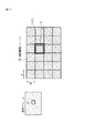
補間画像バッファ101(121)は、図12に示すように、M×Nの一定の大きさの矩形で分割される。分割領域の大きさは、ブロックあるいはマクロブロックと等しい大きさでも良いし、それよりも大きくても良い。または、分割領域の大きさは、ブロックあるいはマクロブロックより小さくても良い。すなわち、分割領域の大きさは、システムに合った大きさと設定されれば良い。
【0081】
始めに、各分割領域は未定義として初期化しておく。
【0082】
図13を参照して説明するに、動き予測・補償部24が、参照フレーム内の所定の部分の予測画像Pを処理に必要であり、補間画像バッファ101から読み出す必要がある場合、補間画像バッファ101に記憶されている画像データから、予測画像Pに対応した領域P’のデータを読み出す。領域P’に対応するデータだけを読み出すようにしても良いが、領域P’を含む分割領域S(P)のデータを読み出すようにしても良い。
【0083】
分割領域S(P)を読み出すようにした場合、予めフレームを何個の領域に分割するかなどを設定しておく必要がある。設定してある場合、領域P’を含む分割領域S(P)を読み出せばよい。
【0084】
分割領域S(P)が未定義の場合、フレームメモリ23の対応する領域から、定義された補間計算により補間画像を生成し、図14に示すように補間画像バッファ101の分割領域S(P)に格納するようにしても良い。動き予測・補償部24が要求した予測画像Pは、図14に示すように補間画像バッファ101から獲得される。
【0085】
予測画像Pに対応した領域を含む分割領域S(P)が、すでに補間画像バッファ101に書き込まれていた場合、分割領域S(P)に格納されたデータが用いられて予測画像Pが獲得される。
【0086】
図15に示すように、予測画像Pに対応した領域P’が、複数の分割領域S(P)に含まれる場合、各分割領域S(P)に対して上述したような処理を行えばよい。
【0087】
ここで、補間精度が1/4画素精度モードと設定され、補間画像バッファ101に1/4画像精度までの画像データがされると設定されているとき、予測画像として1/4画素精度が要求された際、補間画像バッファ101に記憶されている画像データ内から直接読み出され、用いられる。
【0088】
または、補間画像バッファ101に1/2画像精度までの画像データが格納されると設定された場合、予測画像として1/2画素精度の画像データが必要とされたとき、補間画像バッファ101から読み出された画像データがそのまま用いられ、予測画像として1/4画素精度の画像データが必要とされたとき、補間画像バッファ101から読み出された画像データが中間値とされて、さらに線形内挿などの計算によって1/4画素精度が求められる。
【0089】
補間精度が1/8画素精度モードと設定され、補間画像バッファ101に1/8画像精度までの画像データが格納されると設定されているとき、予測画像として1/8画素精度が要求した際、補間画像バッファ101に記憶されている画像データ内から直接読み出され、用いられる。
【0090】
または、補間画像バッファ101に1/4画像精度までの画像データが格納されると設定された場合、予測画像として1/4画素精度の画像データが必要とされたとき、補間画像バッファ101から読み出された画像データがそのまま用いられ、予測画像が1/8画素精度の画像データが必要とされたとき、補間画像バッファ101から読み出された画像データが中間値とされて、さらに線形内挿などの計算によって1/8画素精度の画像が求められる。
【0091】
VOP境界外からの動き補償を許可する場合、図16に示すように補間画像バッファ101の周囲にPadding領域を設けて(補間画像バッファ101に記憶される画像としてPadding領域が含まれるように設定しておき)、上述した場合と同様に扱われるようにしても良い。
【0092】
図17は、本発明を適用した画像情報変換装置131の一実施の形態の構成を示す図である。図17に示した画像情報変換装置131は、動き予測補償部132、セレクタ133、フレームメモリ134、補間画像バッファ135、および遅延バッファ136から構成されている。
【0093】
図17に示した画像情報変換装置131において、動き予測部132は、入力画像情報と、補間画像バッファ135に格納されている参照フレームとにより、フレーム間の動きを予測し、補間画像を生成する。生成された補間画像は、一旦、遅延バッファ136に格納される。セレクタ133は、目的とする更新周波数に合わせて、入力された画像情報と遅延バッファ136に格納された補間画像の画像情報を適宜切り替えて出力する。
【0094】
このような処理により、例えば、図4に示すように、入力画像情報の間に補間フレームを挿入し、フレーム枚数を増加させることで、更新周波数を上げることが可能である。また逆に、図5に示すように、入力画像情報を削除(入力フレームを削除)し、補間フレームを挿入し、全体としてフレーム枚数を減少させることで、更新周波数を下げることも可能である。すなわち、このような処理を行うことにより、画像情報変換装置131において、フレームレートが変換される。
【0095】
入力画像1枚につき補間画像を1枚挿入することで、25Hzの更新周波数の画像信号を50Hzの更新周波数の画像信号に変換することが可能である。
【0096】
上述した実施の形態においては、ブロックマッチング法における動作原理を例に挙げて説明したが、本発明が適用できる範囲は、これに限らず、他の動き予測・補償の方式に対しても適用可能である。例えば、分割領域S(P)の大きさをマクロブロックの大きさよりも大きく設定したような場合、オーバーラップ動き補償(Michael T. Orchard and Gary J. Sullivan; Overlapped Block Motion Compensation: An Estimation-Theoretic Approach; IEEE Transactions on image processing, vol 3. No. 5, September 1994)などの処理に、本発明を適用することが可能である。
【0097】
上述した一連の処理は、ハードウェアにより実行させることもできるが、ソフトウェアにより実行させることもできる。一連の処理をソフトウェアにより実行させる場合には、そのソフトウェアを構成するプログラムが専用のハードウェアに組み込まれているコンピュータ、または、各種のプログラムをインストールすることで、各種の機能を実行することが可能な、例えば汎用のパーソナルコンピュータなどに、記録媒体からインストールされる。記録媒体の説明の前に、記録媒体を扱うパーソナルコンピュータについて簡単に説明する。
【0098】
図18は、汎用のパーソナルコンピュータの内部構成例を示す図である。パーソナルコンピュータのCPU(Central Processing Unit)211は、ROM(Read Only Memory)212に記憶されているプログラムに従って各種の処理を実行する。RAM(Random Access Memory)213には、CPU211が各種の処理を実行する上において必要なデータやプログラムなどが適宜記憶される。入出力インタフェース215は、キーボードやマウスから構成される入力部216が接続され、入力部216に入力された信号をCPU211に出力する。また、入出力インタフェース215には、ディスプレイやスピーカなどから構成される出力部7も接続されている。
【0099】
さらに、入出力インタフェース215には、ハードディスクなどから構成される記憶部218、および、インターネットなどのネットワークを介して他の装置とデータの授受を行う通信部219も接続されている。ドライブ220は、磁気ディスク231、光ディスク232、光磁気ディスク233、半導体メモリ234などの記録媒体からデータを読み出したり、データを書き込んだりするときに用いられる。
【0100】
記録媒体は、図18に示すように、パーソナルコンピュータとは別に、ユーザにプログラムを提供するために配布される、プログラムが記録されている磁気ディスク231(フレキシブルディスクを含む)、光ディスク232(CD-ROM(Compact Disc-Read Only Memory),DVD(Digital Versatile Disc)を含む)、光磁気ディスク233(MD(Mini-Disc)(登録商標)を含む)、若しくは半導体メモリ234などよりなるパッケージメディアにより構成されるだけでなく、コンピュータに予め組み込まれた状態でユーザに提供される、プログラムが記憶されているROM212や記憶部218が含まれるハードディスクなどで構成される。
【0101】
なお、本明細書において、媒体により提供されるプログラムを記述するステップは、記載された順序に従って、時系列的に行われる処理は勿論、必ずしも時系列的に処理されなくとも、並列的あるいは個別に実行される処理をも含むものである。
【0102】
また、本明細書において、システムとは、複数の装置により構成される装置全体を表すものである。
【0103】
【発明の効果】
以上の如く本発明によれば、既に生成されている画像データを繰り返し生成するようなことを防ぐことができ、その生成に係る演算量を削減することができ、予測補償の処理の高速化をはかることができる。
【図面の簡単な説明】
【図1】従来の画像情報符号化装置の一例の構成を示す図である。
【図2】従来の画像情報復号装置の一例の構成を示す図である。
【図3】更新周波数を変換する変換装置の一例の構成を示す図である。
【図4】補間フレームの挿入によりフレーム数が増加している場合について説明するための図である。
【図5】入力フレームの削除と補間フレームの挿入によりフレーム数が減少している場合について説明するための図である。
【図6】VOP境界外からの動き補償を説明するための図である。
【図7】1/4画素精度の動き予測補償処理について説明する図である。
【図8】1/8画素精度の動き予測補償処理について説明する図である。
【図9】1/8画素精度の補間方法について説明する図である。
【図10】本発明を適用した画像情報符号化装置の一実施の形態の構成を示す図である。
【図11】本発明を適用した画像情報復号装置の一実施の形態の構成を示す図である。
【図12】補間画像バッファと領域分割の関係を説明するための図である。
【図13】参照フレームにおける予測画像P、補間画像バッファにおける予測画像領域P’および分割領域S(P)の関係を説明するための図である。
【図14】分割領域からの予測画像の獲得について説明する図である。
【図15】予測画像領域P’が複数の分割領域に含まれている状況について説明するための図である。
【図16】Padding領域を含む補間画像バッファについて説明するための図である。
【図17】本発明を適用した更新周波数を変換する装置の一実施の形態の構成を示す図である。
【図18】媒体を説明する図である。
【符号の説明】
23 フレームメモリ, 24 動き予測・補償部, 50 フレームメモリ, 51 動き予測・補償部, 100 画像情報符号化装置, 101 補間画像バッファ, 120 画像情報復号装置, 121 補間画像バッファ, 131 画像情報変換装置, 132 動き予測補償部, 133 セレクタ,134 フレームメモリ, 135 補間画像バッファ, 136 遅延バッファ[0001]
BACKGROUND OF THE INVENTION
The present invention relates to an image processing apparatus and method, a recording medium, and a program, and in particular, image information (bitstream) compressed by orthogonal transformation such as discrete cosine transformation or Karhunen-Labe transformation and motion compensation, satellite broadcasting, cable television. Encoding / decoding of image information used for transmission / reception via network media such as John Broadcasting, the Internet, or processing on storage media such as optical discs, magnetic discs, flash memories, etc. The present invention relates to an image processing apparatus and method, a recording medium, and a program suitable for use in an apparatus that performs conversion.
[0002]
[Prior art]
In recent years, image information is handled as digital data, and MPEG (compressed by orthogonal transform such as discrete cosine transform and motion compensation is used for the purpose of efficient transmission and storage of information. A device conforming to a scheme such as Moving Picture Expert Group) is becoming popular for both information distribution in broadcasting stations and information reception in general households.
[0003]
In particular, MPEG2 (ISO / IEC 13818-2) is a standard defined as a general-purpose image compression system, which covers both interlaced scanning images and progressive scanning images, as well as standard resolution images and high-definition images. As represented by the DVD (Digital Versatile Disk) standard, it is widely used in a wide range of applications for professional use and consumer use.
[0004]
By using this MPEG2 compression method, for example, 4 to 8 Mbps for a standard resolution interlaced scanning image having 720 × 480 pixels, and 18 to 22 Mbps for a high resolution interlaced scanning image having 1920 × 1088 pixels, for example. By assigning a code amount (bit rate), it is possible to realize a high compression rate and good image quality.
[0005]
MPEG2 was mainly intended for high-quality encoding suitable for broadcasting, but since it did not support encoding systems with higher compression rates, the MPEG4 encoding standard was standardized. Regarding the image coding system, the standard was approved as an international standard as ISO / IEC 14496-2 in December 1998.
[0006]
Furthermore, in recent years, H.26L (ITU-T Q6 / 16) by the ITU-T (International Telecommunication Union-Telecommunication Standardization Sector), which is the telecommunications standardization department of the International Telecommunication Union, was originally intended for video coding for video conferencing. VCEG) is being standardized. H. It is known that H.26L achieves higher encoding efficiency compared to encoding methods such as MPEG2 and MPEG4, although a larger amount of calculation is required for encoding and decoding.
[0007]
In addition, as part of MPEG4 activities, this H.264 Based on H.26L. Standardization of coding technology that realizes higher coding efficiency, including functions not supported by 26L, is being carried out jointly with ITU-T as JVT (Joint Video Team).
[0008]
Here, image compression by orthogonal transform such as discrete cosine transform or Karhunen-Loeve transform and motion compensation will be described. FIG. 1 is a diagram illustrating a configuration of an example of a conventional image information encoding device.
[0009]
In the image
[0010]
Here, the
[0011]
The
[0012]
The
[0013]
The behavior of the
[0014]
In addition, the
[0015]
The
[0016]
Further, the
[0017]
In contrast to intra coding, in the case of inter coding, the image information input to the
[0018]
Next, FIG. 2 shows a configuration of an example of an image information decoding device corresponding to the image
[0019]
The
[0020]
The
[0021]
Here, when the target frame is intra-coded, the image information subjected to the inverse orthogonal transform process is stored in the
[0022]
When the target frame is inter-coded, the motion prediction /
[0023]
FIG. 3 is a diagram illustrating a configuration of an example of the image
[0024]
In the image
[0025]
By such processing, for example, as shown in FIG. 4, it is possible to increase the update frequency by inserting interpolation frames between input image information and increasing the number of frames. Conversely, as shown in FIG. 5, it is possible to lower the update frequency by deleting the input image information (deleting the input frame), inserting an interpolation frame, and reducing the number of frames. That is, by performing such processing, the frame rate is converted in the image
[0026]
By the way, in MPEG4, as shown in FIG. 6, it is prescribed | regulated that a motion vector may point out of a VOP (Video Object Plane) boundary. When the region specified by the motion vector is outside the VOP boundary, information on pixels located on the VOP boundary is used as a predicted value. H. Also in 26L, it is defined that the motion vector may point outside the VOP boundary.
[0027]
H. In 26L, high-precision motion prediction / compensation processing such as 1/4 and 1/8 pixels is defined. In order to generate this decimal accuracy prediction image, it is specified to combine several tap filters and linear interpolation.
[0028]
H. A motion prediction / compensation process with 1/4 and 1/8 pixel accuracy defined by 26L will be described. FIG. It is a figure for demonstrating the motion prediction compensation process of the 1/4 pixel precision defined in 26L. First, based on the pixels stored in the frame memory, pixel values with ½ pixel accuracy are generated using a 6-tap FIR (Finite Impulse Response) filter in each of the horizontal and vertical directions. The following is defined as an example of the FIR filter coefficient.
(1-5 20 20-5 1) // 32
In this FIR filter coefficient, // indicates a division with rounding (rounding off). In the present specification, // indicates a division with rounding.
[0029]
The pixel value with 1/4 pixel accuracy is obtained by linear interpolation from two adjacent pixel values with 1/2 pixel accuracy obtained above.
[0030]
FIG. It is a figure for demonstrating the motion prediction compensation process of 1/8 pixel precision defined in 26L. First, based on the pixels stored in the frame memory, pixel values with 1/4, 2/4, and 3/4 pixel accuracy are generated using 8-tap FIR filters in the horizontal and vertical directions, respectively. . The following are determined as FIR filter coefficients, respectively.
(−3 12−37 229 71−21 6−1) // 256
(−3 12 −39 158 158 −39 12 −3) // 256
(-1 6-21 71 229-37 12-3) // 256
[0031]
The pixel value with 1/8 pixel accuracy is obtained by linear interpolation of two pixel values as shown in FIG. 8 from the pixel values with 1/4, 2/4, and 3/4 pixel accuracy generated as described above. Obtained by.
[0032]
[Problems to be solved by the invention]
When obtaining a predicted image by motion prediction compensation in an encoding device that can select frame motion prediction compensation or field motion prediction compensation in units of macroblocks and a decoding device that decodes image compression information from the encoding device, decimal precision The amount of calculation for acquiring the predicted image becomes a problem. That is, as described above, the calculation of the decimal precision interpolation pixel is performed by a several tap filter and linear interpolation. However, performing these calculations for each pixel is a heavy process and may affect other processes.
[0033]
In particular, in motion prediction processing, many pixels located in the vicinity of a predetermined area are repeatedly referred to many times. Therefore, when an image signal is encoded or decoded, a predicted image is acquired at high speed. It was important to do, but there was a problem that it was difficult.
[0034]
The present invention has been made in view of such a situation, and an object of the present invention is to reduce processing for calculating an interpolation pixel so that the interpolation pixel can be acquired at high speed.
[0035]
[Means for Solving the Problems]
The image processing apparatus of the present inventionIn a state where a frame memory for storing a frame and an interpolation image with 1 / N pixel accuracy are divided into divided areas of a certain sizeStorage means for storing, and the storage means stored in the storage meansOf the interpolated image, the required divided areaPredictive compensation means for performing prediction compensation processing usingWhen the divided region is undefined, the interpolation image is generated by the defined interpolation calculation from the corresponding region of the frame stored in the frame memory, and stored in the storage unit.The prediction compensation means provides 1 / N pixel accuracy for prediction compensation.Interpolated imageOf the 1 / N pixel accuracy stored in the storage
[0036]
The N or the M can be any one of 2, 4, and 8.
The storage means may store the same number of frames as the frame memory.
[0059]
The storage means may have a padding area for dealing with motion compensation from outside the VOP boundary.
[0060]
The prediction compensation means may perform orthogonal transform by discrete cosine transform or Karhunen-Loeve transform and overlap motion prediction compensation with decimal pixel accuracy.
[0061]
The image processing method of the present invention includes:A frame memory for storing the frame; and a storage unit for storing the interpolated image with 1 / N pixel accuracy in a state where the interpolated image is divided into divided regions of a certain size.In the image processing method of the image processing apparatus, the storage unit stores the storage unit.Of the interpolated image, the required divided areaA prediction compensation step of performing a prediction compensation process usingWhen the divided region is undefined, the interpolation image is generated by the defined interpolation calculation from the corresponding region of the frame stored in the frame memory, and stored in the storage unit.In the prediction compensation step, the 1 / N pixel accuracy is used for the prediction compensation.Interpolated imageOf the 1 / N pixel accuracy stored in the storage
[0062]
The program of the recording medium of the present invention isA frame memory for storing the frame; and a storage unit for storing the interpolated image with 1 / N pixel accuracy in a state where the interpolated image is divided into divided regions of a certain size.The image processing apparatus stores the storage unit stored in the storage unit.Of the interpolated image, the required divided areaA prediction compensation step of performing a prediction compensation process usingWhen the divided region is undefined, the interpolation image is generated by the defined interpolation calculation from the corresponding region of the frame stored in the frame memory, and stored in the storage unit.In the prediction compensation step, the 1 / N pixel accuracy is used for the prediction compensation.Interpolated imageOf the 1 / N pixel accuracy stored in the storage
[0063]
The program of the present inventionA frame memory for storing the frame; and a storage unit for storing the interpolated image with 1 / N pixel accuracy in a state where the interpolated image is divided into divided regions of a certain size.The image processing apparatus stores the storage unit stored in the storage unit.Of the interpolated image, the required divided areaA prediction compensation step of performing a prediction compensation process usingWhen the divided region is undefined, the interpolation image is generated by the defined interpolation calculation from the corresponding region of the frame stored in the frame memory, and stored in the storage unit.In the prediction compensation step, the 1 / N pixel accuracy is used for the prediction compensation.Interpolated imageOf the 1 / N pixel accuracy stored in the storage
[0066]
In the image processing apparatus and method and the program of the present invention, the generated image data with decimal pixel accuracy is temporarily stored, and the stored image data is read out as necessary, so that the prediction compensation processing is performed. Done.
[0068]
DETAILED DESCRIPTION OF THE INVENTION
Embodiments of the present invention will be described below with reference to the drawings. FIG. 10 is a diagram showing a configuration of an embodiment of an image information encoding apparatus to which the image processing apparatus of the present invention is applied. In the image
[0069]
The image
[0070]
The configuration of the other parts is the same as that of the image
[0071]
FIG. 11 shows the configuration of an embodiment of an image information decoding apparatus of an image processing apparatus to which the present invention is applied, corresponding to the image
[0072]
The image
[0073]
The configuration of the other parts is the same as that of the image
[0074]
In the present embodiment, the operation until the image data stored in the
[0075]
Here, in consideration of the above, the image data stored in the
[0076]
The interpolated
[0077]
However, the size of the image frame per frame depends on the interpolation pixel accuracy. That is, when the interpolated image buffer 101 (121) holds an interpolated image with a half-pixel accuracy, the vertical and horizontal pixels are twice as large as the size of the image frame stored in the frame memory 23 (50). An image frame with a number.
[0078]
When the interpolated image buffer 101 (121) holds an interpolated image with 1/4 pixel accuracy, the vertical and horizontal pixels are four times larger than the size of the image frame stored in the frame memory 23 (50). An image frame with a number.
[0079]
When the interpolated image buffer 101 (121) holds an interpolated image with 1/8 pixel accuracy, the vertical and horizontal pixels are eight times larger than the size of the image frame stored in the frame memory 23 (50). An image frame with a number.
[0080]
As shown in FIG. 12, the interpolated image buffer 101 (121) is divided into rectangles having a fixed size of M × N. The size of the divided area may be equal to or larger than the block or macroblock. Alternatively, the size of the divided area may be smaller than the block or the macro block. That is, the size of the divided area may be set to a size suitable for the system.
[0081]
First, each divided area is initialized as undefined.
[0082]
As will be described with reference to FIG. 13, when the motion prediction /
[0083]
When the divided area S (P) is read out, it is necessary to set in advance how many areas the frame is divided into. If set, the divided area S (P) including the area P ′ may be read.
[0084]
When the divided area S (P) is undefined, an interpolation image is generated from the corresponding area of the
[0085]
When the divided area S (P) including the area corresponding to the predicted image P has already been written in the interpolated
[0086]
As illustrated in FIG. 15, when the region P ′ corresponding to the predicted image P is included in the plurality of divided regions S (P), the above-described process may be performed on each divided region S (P). .
[0087]
Here, when the interpolation accuracy is set to the 1/4 pixel accuracy mode and the image data up to 1/4 image accuracy is set in the
[0088]
Alternatively, when it is set that image data up to ½ image accuracy is stored in the interpolated
[0089]
When the interpolation accuracy is set to 1/8 pixel accuracy mode and the image data up to 1/8 image accuracy is stored in the
[0090]
Alternatively, when it is set that image data up to 1/4 image accuracy is stored in the interpolated
[0091]
When motion compensation from outside the VOP boundary is permitted, a padding area is provided around the interpolated
[0092]
FIG. 17 is a diagram showing a configuration of an embodiment of an image
[0093]
In the image
[0094]
By such processing, for example, as shown in FIG. 4, it is possible to increase the update frequency by inserting interpolation frames between input image information and increasing the number of frames. Conversely, as shown in FIG. 5, it is also possible to lower the update frequency by deleting the input image information (deleting the input frame), inserting an interpolation frame, and reducing the number of frames as a whole. That is, by performing such processing, the frame rate is converted in the image
[0095]
By inserting one interpolation image per input image, it is possible to convert an image signal with an update frequency of 25 Hz into an image signal with an update frequency of 50 Hz.
[0096]
In the embodiment described above, the operation principle in the block matching method has been described as an example. However, the scope to which the present invention can be applied is not limited to this, and can be applied to other motion prediction / compensation methods. It is. For example, when the size of the divided region S (P) is set larger than the size of the macro block, the overlap motion compensation (Michael T. Orchard and Gary J. Sullivan; Overlapped Block Motion Compensation: An Estimation-Theoretic Approach) IEEE Transactions on image processing, vol 3. No. 5, September 1994), etc., can be applied to the present invention.
[0097]
The series of processes described above can be executed by hardware, but can also be executed by software. When a series of processing is executed by software, various functions can be executed by installing a computer in which the programs that make up the software are installed in dedicated hardware, or by installing various programs. For example, it is installed from a recording medium in a general-purpose personal computer or the like. Before describing the recording medium, a personal computer handling the recording medium will be briefly described.
[0098]
FIG. 18 is a diagram illustrating an internal configuration example of a general-purpose personal computer. A CPU (Central Processing Unit) 211 of the personal computer executes various processes according to a program stored in a ROM (Read Only Memory) 212. A RAM (Random Access Memory) 213 appropriately stores data and programs necessary for the
[0099]
Further, a
[0100]
As shown in FIG. 18, the recording medium is distributed to provide a program to the user separately from the personal computer, and a magnetic disk 231 (including a flexible disk) on which the program is recorded, an optical disk 232 (CD- Consists of package media including ROM (Compact Disc-Read Only Memory), DVD (including Digital Versatile Disc), magneto-optical disc 233 (including MD (Mini-Disc) (registered trademark)), or
[0101]
In this specification, the steps for describing the program provided by the medium are performed in parallel or individually in accordance with the described order, as well as the processing performed in time series, not necessarily in time series. The process to be executed is also included.
[0102]
Further, in this specification, the system represents the entire apparatus constituted by a plurality of apparatuses.
[0103]
【The invention's effect】
As described above, the present inventionAccording toIt is possible to prevent the image data that has already been generated from being repeatedly generated, the amount of calculation related to the generation can be reduced, and the speed of prediction compensation processing can be increased.
[Brief description of the drawings]
FIG. 1 is a diagram illustrating a configuration of an example of a conventional image information encoding device.
FIG. 2 is a diagram illustrating a configuration of an example of a conventional image information decoding device.
FIG. 3 is a diagram illustrating a configuration of an example of a conversion device that converts an update frequency.
FIG. 4 is a diagram for describing a case where the number of frames increases due to insertion of an interpolation frame.
FIG. 5 is a diagram for explaining a case where the number of frames is decreased due to deletion of an input frame and insertion of an interpolation frame.
FIG. 6 is a diagram for explaining motion compensation from outside the VOP boundary;
FIG. 7 is a diagram illustrating a motion prediction / compensation process with ¼ pixel accuracy.
FIG. 8 is a diagram for explaining motion prediction compensation processing with 1/8 pixel accuracy.
FIG. 9 is a diagram illustrating an interpolation method with 1/8 pixel accuracy.
FIG. 10 is a diagram illustrating a configuration of an embodiment of an image information encoding device to which the present invention has been applied.
FIG. 11 is a diagram illustrating a configuration of an embodiment of an image information decoding device to which the present invention has been applied.
FIG. 12 is a diagram for explaining a relationship between an interpolation image buffer and region division.
FIG. 13 is a diagram for explaining a relationship among a predicted image P in a reference frame, a predicted image region P ′ in an interpolated image buffer, and a divided region S (P).
FIG. 14 is a diagram illustrating acquisition of a predicted image from a divided region.
FIG. 15 is a diagram for describing a situation in which a predicted image region P ′ is included in a plurality of divided regions.
FIG. 16 is a diagram for describing an interpolated image buffer including a padding area.
FIG. 17 is a diagram showing a configuration of an embodiment of an apparatus for converting an update frequency to which the present invention is applied.
FIG. 18 is a diagram illustrating a medium.
[Explanation of symbols]
23 frame memory, 24 motion prediction / compensation unit, 50 frame memory, 51 motion prediction / compensation unit, 100 image information encoding device, 101 interpolation image buffer, 120 image information decoding device, 121 interpolation image buffer, 131 image information conversion device , 132 motion prediction compensation unit, 133 selector, 134 frame memory, 135 interpolated image buffer, 136 delay buffer
Claims (7)
1/N画素精度の補間画像を一定の大きさの分割領域で分割した状態で記憶する記憶手段と、
前記記憶手段に記憶されている前記補間画像のうち、必要とされる前記分割領域を用いて予測補償の処理を実行する予測補償手段と
を備え、
前記分割領域が未定義の場合、前記フレームメモリに記憶されている前記フレームの対応する領域から、定義された補間計算により前記補間画像を生成し、前記記憶手段に記憶し、
前記予測補償手段は、予測補償に1/N画素精度の補間画像が必要な場合、前記記憶手段に記憶されている前記1/N画素精度の補間画像を読み出し、そのまま用い、
予測補償に1/M(M>N)画素精度の補間画像が必要な場合、前記記憶手段に記憶されている前記1/N画素精度の補間画像を読み出し、その補間画像に所定の数のタップのFIRフィルタを用いて1/M画素精度の補間画像を生成するか、または、その補間画像に線型内挿を用いて1/M画素精度の補間画像を生成して予測補償を行う
画像処理装置。 A frame memory for storing frames;
Storage means for storing an interpolated image with 1 / N pixel accuracy in a state of being divided by a divided region of a certain size ;
Prediction compensation means for performing prediction compensation processing using the required divided region of the interpolated image stored in the storage means, and
When the divided region is undefined, the interpolation image is generated by the defined interpolation calculation from the corresponding region of the frame stored in the frame memory, and stored in the storage unit.
When the 1 / N pixel accuracy interpolation image is required for the prediction compensation, the prediction compensation unit reads the 1 / N pixel accuracy interpolation image stored in the storage unit and uses it as it is.
If the prediction compensation 1 / M (M> N) pixel precision interpolation image is required, reads out the interpolated image of the 1 / N pixel accuracy stored in the storage means, a predetermined number of taps in the interpolation image whether to generate an interpolated image of the 1 / M-pixel precision using an FIR filter, or an image processing apparatus for generating and prediction compensation of the interpolated image 1 / M-pixel precision using a linear interpolation in the interpolation image .
請求項1に記載の画像処理装置。The image processing apparatus according to claim 1, wherein the N or the M is 2, 4, or 8.
請求項1に記載の画像処理装置。The image processing apparatus according to claim 1, wherein the storage unit stores the same number of frames as the frame memory .
ことを特徴とする請求項1に記載の画像処理装置。The image processing apparatus according to claim 1, wherein the prediction compensation unit performs orthogonal transformation by discrete cosine transformation or Karhunen-Labe transformation and overlapped motion prediction compensation with decimal pixel accuracy.
1/N画素精度の補間画像を一定の大きさの分割領域で分割した状態で記憶する記憶手段と
を備える画像処理装置の画像処理方法において、
前記記憶手段に記憶されている前記補間画像のうち、必要とされる前記分割領域を用いて予測補償の処理を実行する予測補償ステップ
を含み、
前記分割領域が未定義の場合、前記フレームメモリに記憶されている前記フレームの対応する領域から、定義された補間計算により前記補間画像を生成し、前記記憶手段に記憶し、
前記予測補償ステップの処理は、予測補償に1/N画素精度の補間画像が必要な場合、前記記憶手段に記憶されている前記1/N画素精度の補間画像を読み出し、そのまま用い、
予測補償に1/M(M>N)画素精度の補間画像が必要な場合、前記記憶手段に記憶されている前記1/N画素精度の補間画像を読み出し、その補間画像に所定の数のタップのFIRフィルタを用いて1/M画素精度の補間画像を生成するか、または、その補間画像に線型内挿を用いて1/M画素精度の補間画像を生成して予測補償を行う
画像処理方法。 A frame memory for storing frames;
Storage means for storing an interpolated image of 1 / N pixel accuracy in a state of being divided by a divided region of a certain size;
In an image processing method of an image processing apparatus comprising:
A prediction compensation step of performing a prediction compensation process using the required divided region of the interpolated image stored in the storage means,
When the divided region is undefined, the interpolation image is generated by the defined interpolation calculation from the corresponding region of the frame stored in the frame memory, and stored in the storage unit.
The processing of the prediction compensation step, when the interpolation image 1 / N pixel accuracy prediction compensation is required, reads out the interpolated image of the 1 / N pixel accuracy stored in the storage means, used as it is,
If the prediction compensation 1 / M (M> N) pixel precision interpolation image is required, reads out the interpolated image of the 1 / N pixel accuracy stored in the storage means, a predetermined number of taps in the interpolation image whether to generate an interpolated image of the 1 / M-pixel precision using an FIR filter, or an image processing method for performing prediction compensation by generating an interpolated image of the 1 / M-pixel precision using a linear interpolation in the interpolation image .
1/N画素精度の補間画像を一定の大きさの分割領域で分割した状態で記憶する記憶手段と
を備える画像処理装置に、
前記記憶手段に記憶されている前記補間画像のうち、必要とされる前記分割領域を用いて予測補償の処理を実行する予測補償ステップ
を含み、
前記分割領域が未定義の場合、前記フレームメモリに記憶されている前記フレームの対応する領域から、定義された補間計算により前記補間画像を生成し、前記記憶手段に記憶し、
前記予測補償ステップの処理は、予測補償に1/N画素精度の補間画像が必要な場合、前記記憶手段に記憶されている前記1/N画素精度の補間画像を読み出し、そのまま用い、
予測補償に1/M(M>N)画素精度の補間画像が必要な場合、前記記憶手段に記憶されている前記1/N画素精度の補間画像を読み出し、その補間画像に所定の数のタップのFIRフィルタを用いて1/M画素精度の補間画像を生成するか、または、その補間画像に線型内挿を用いて1/M画素精度の補間画像を生成して予測補償を行う
処理を実行させるコンピュータが読み取り可能なプログラムが記録されている記録媒体。 A frame memory for storing frames;
Storage means for storing an interpolated image of 1 / N pixel accuracy in a state of being divided by a divided region of a certain size;
An image processing apparatus comprising:
A prediction compensation step of performing a prediction compensation process using the required divided region of the interpolated image stored in the storage means,
When the divided region is undefined, the interpolation image is generated by the defined interpolation calculation from the corresponding region of the frame stored in the frame memory, and stored in the storage unit.
The processing of the prediction compensation step, when the interpolation image 1 / N pixel accuracy prediction compensation is required, reads out the interpolated image of the 1 / N pixel accuracy stored in the storage means, used as it is,
If the prediction compensation 1 / M (M> N) pixel precision interpolation image is required, reads out the interpolated image of the 1 / N pixel accuracy stored in the storage means, a predetermined number of taps in the interpolation image whether to generate an interpolated image of the 1 / M-pixel precision using an FIR filter, or performs processing to prediction compensation by generating an interpolated image of the 1 / M-pixel precision using a linear interpolation in the interpolation image A recording medium on which a computer readable program is recorded.
1/N画素精度の補間画像を一定の大きさの分割領域で分割した状態で記憶する記憶手段と
を備える画像処理装置に、
前記記憶手段に記憶されている前記補間画像のうち、必要とされる前記分割領域を用いて予測補償の処理を実行する予測補償ステップ
を含み、
前記分割領域が未定義の場合、前記フレームメモリに記憶されている前記フレームの対応する領域から、定義された補間計算により前記補間画像を生成し、前記記憶手段に記憶し、
前記予測補償ステップの処理は、予測補償に1/N画素精度の補間画像が必要な場合、前記記憶手段に記憶されている前記1/N画素精度の補間画像を読み出し、そのまま用い、
予測補償に1/M(M>N)画素精度の補間画像が必要な場合、前記記憶手段に記憶されている前記1/N画素精度の補間画像を読み出し、その補間画像に所定の数のタップのFIRフィルタを用いて1/M画素精度の補間画像を生成するか、または、その補間画像に線型内挿を用いて1/M画素精度の補間画像を生成して予測補償を行う
処理を実行させるコンピュータが読み取り可能なプログラム。 A frame memory for storing frames;
Storage means for storing an interpolated image of 1 / N pixel accuracy in a state of being divided by a divided region of a certain size;
An image processing apparatus comprising:
A prediction compensation step of performing a prediction compensation process using the required divided region of the interpolated image stored in the storage means,
When the divided region is undefined, the interpolation image is generated by the defined interpolation calculation from the corresponding region of the frame stored in the frame memory, and stored in the storage unit.
The processing of the prediction compensation step, when the interpolation image 1 / N pixel accuracy prediction compensation is required, reads out the interpolated image of the 1 / N pixel accuracy stored in the storage means, used as it is,
If the prediction compensation 1 / M (M> N) pixel precision interpolation image is required, reads out the interpolated image of the 1 / N pixel accuracy stored in the storage means, a predetermined number of taps in the interpolation image whether to generate an interpolated image of the 1 / M-pixel precision using an FIR filter, or performs processing to prediction compensation by generating an interpolated image of the 1 / M-pixel precision using a linear interpolation in the interpolation image A computer readable program.
Priority Applications (1)
| Application Number | Priority Date | Filing Date | Title |
|---|---|---|---|
| JP2002154077A JP4318019B2 (en) | 2002-05-28 | 2002-05-28 | Image processing apparatus and method, recording medium, and program |
Applications Claiming Priority (1)
| Application Number | Priority Date | Filing Date | Title |
|---|---|---|---|
| JP2002154077A JP4318019B2 (en) | 2002-05-28 | 2002-05-28 | Image processing apparatus and method, recording medium, and program |
Publications (3)
| Publication Number | Publication Date |
|---|---|
| JP2003348596A JP2003348596A (en) | 2003-12-05 |
| JP2003348596A5 JP2003348596A5 (en) | 2005-10-06 |
| JP4318019B2 true JP4318019B2 (en) | 2009-08-19 |
Family
ID=29770959
Family Applications (1)
| Application Number | Title | Priority Date | Filing Date |
|---|---|---|---|
| JP2002154077A Expired - Fee Related JP4318019B2 (en) | 2002-05-28 | 2002-05-28 | Image processing apparatus and method, recording medium, and program |
Country Status (1)
| Country | Link |
|---|---|
| JP (1) | JP4318019B2 (en) |
Families Citing this family (9)
| Publication number | Priority date | Publication date | Assignee | Title |
|---|---|---|---|---|
| NO320114B1 (en) * | 2003-12-05 | 2005-10-24 | Tandberg Telecom As | Improved calculation of interpolated pixel values |
| KR100955161B1 (en) | 2004-05-04 | 2010-04-28 | 콸콤 인코포레이티드 | Method and apparatus for motion compensated frame rate up conversion |
| US20050286777A1 (en) * | 2004-06-27 | 2005-12-29 | Roger Kumar | Encoding and decoding images |
| RU2370909C2 (en) * | 2004-07-01 | 2009-10-20 | Квэлкомм Инкорпорейтед | Method and device for use of frame conversion methods with increase of frame frequency in coding of scalable video |
| CA2574297A1 (en) | 2004-07-20 | 2006-02-02 | Qualcomm Incorporated | Method and apparatus for encoder assisted-frame rate up conversion (ea-fruc) for video compression |
| US8553776B2 (en) | 2004-07-21 | 2013-10-08 | QUALCOMM Inorporated | Method and apparatus for motion vector assignment |
| US8634463B2 (en) | 2006-04-04 | 2014-01-21 | Qualcomm Incorporated | Apparatus and method of enhanced frame interpolation in video compression |
| US8750387B2 (en) | 2006-04-04 | 2014-06-10 | Qualcomm Incorporated | Adaptive encoder-assisted frame rate up conversion |
| JP4781301B2 (en) * | 2007-03-06 | 2011-09-28 | 日本放送協会 | Encoding side motion compensation device and decoding side motion compensation device |
-
2002
- 2002-05-28 JP JP2002154077A patent/JP4318019B2/en not_active Expired - Fee Related
Also Published As
| Publication number | Publication date |
|---|---|
| JP2003348596A (en) | 2003-12-05 |
Similar Documents
| Publication | Publication Date | Title |
|---|---|---|
| JP4699685B2 (en) | Signal processing apparatus and electronic apparatus using the same | |
| JP3861698B2 (en) | Image information encoding apparatus and method, image information decoding apparatus and method, and program | |
| JP3720875B2 (en) | Transcoding method and apparatus | |
| JP3686436B2 (en) | Video signal decoding method | |
| KR20060109290A (en) | Image decoding device, image decoding method, and image decoding program | |
| EP1257127A2 (en) | Video transcoder with spatial resolution reduction | |
| US20110176614A1 (en) | Image processing device and method, and program | |
| US20110103486A1 (en) | Image processing apparatus and image processing method | |
| US20030095603A1 (en) | Reduced-complexity video decoding using larger pixel-grid motion compensation | |
| JP2004140473A (en) | Image information coding apparatus, decoding apparatus and method for coding image information, method for decoding | |
| US7903731B2 (en) | Methods and transcoders that estimate an output macroblock and motion vector for video transcoding | |
| JP2001145113A (en) | Device and method for image information conversion | |
| KR20040106364A (en) | System and method for providing single-layer video encoded bitstreams suitable for reduced-complexity decoding | |
| JP2009089332A (en) | Motion prediction method and motion predictor | |
| JP2004520771A (en) | Video transcoder with drift correction | |
| EP2077670A1 (en) | Transcoder, transcoding method, decoder, and decoding method | |
| KR100945826B1 (en) | Image information decoding method and decoder | |
| JP4360093B2 (en) | Image processing apparatus and encoding apparatus and methods thereof | |
| JP2007013298A (en) | Image coding apparatus | |
| JP4318019B2 (en) | Image processing apparatus and method, recording medium, and program | |
| JP2008219205A (en) | Picture information encoder and picture information encoding method | |
| JP4209134B2 (en) | Method and apparatus for upsampling a compressed bitstream | |
| JP2003289544A (en) | Equipment and method for coding image information, equipment and method for decoding image information, and program | |
| WO2017082304A1 (en) | Information compression device, information compression method, recording medium, and encoding device | |
| JP2003348595A (en) | Image processor and image processing method, recording medium and program |
Legal Events
| Date | Code | Title | Description |
|---|---|---|---|
| A521 | Written amendment |
Free format text: JAPANESE INTERMEDIATE CODE: A523 Effective date: 20050527 |
|
| A621 | Written request for application examination |
Free format text: JAPANESE INTERMEDIATE CODE: A621 Effective date: 20050527 |
|
| A977 | Report on retrieval |
Free format text: JAPANESE INTERMEDIATE CODE: A971007 Effective date: 20080121 |
|
| A131 | Notification of reasons for refusal |
Free format text: JAPANESE INTERMEDIATE CODE: A131 Effective date: 20080125 |
|
| A521 | Written amendment |
Free format text: JAPANESE INTERMEDIATE CODE: A523 Effective date: 20080321 |
|
| A131 | Notification of reasons for refusal |
Free format text: JAPANESE INTERMEDIATE CODE: A131 Effective date: 20080414 |
|
| A521 | Written amendment |
Free format text: JAPANESE INTERMEDIATE CODE: A523 Effective date: 20080513 |
|
| TRDD | Decision of grant or rejection written | ||
| A01 | Written decision to grant a patent or to grant a registration (utility model) |
Free format text: JAPANESE INTERMEDIATE CODE: A01 Effective date: 20090430 |
|
| A01 | Written decision to grant a patent or to grant a registration (utility model) |
Free format text: JAPANESE INTERMEDIATE CODE: A01 |
|
| A61 | First payment of annual fees (during grant procedure) |
Free format text: JAPANESE INTERMEDIATE CODE: A61 Effective date: 20090513 |
|
| FPAY | Renewal fee payment (event date is renewal date of database) |
Free format text: PAYMENT UNTIL: 20120605 Year of fee payment: 3 |
|
| FPAY | Renewal fee payment (event date is renewal date of database) |
Free format text: PAYMENT UNTIL: 20120605 Year of fee payment: 3 |
|
| LAPS | Cancellation because of no payment of annual fees |