JP4317224B2 - System, kit and method for measuring membrane diffusion - Google Patents
System, kit and method for measuring membrane diffusion Download PDFInfo
- Publication number
- JP4317224B2 JP4317224B2 JP2006527975A JP2006527975A JP4317224B2 JP 4317224 B2 JP4317224 B2 JP 4317224B2 JP 2006527975 A JP2006527975 A JP 2006527975A JP 2006527975 A JP2006527975 A JP 2006527975A JP 4317224 B2 JP4317224 B2 JP 4317224B2
- Authority
- JP
- Japan
- Prior art keywords
- base
- cavity
- opening
- membrane
- hollow
- Prior art date
- Legal status (The legal status is an assumption and is not a legal conclusion. Google has not performed a legal analysis and makes no representation as to the accuracy of the status listed.)
- Expired - Fee Related
Links
Images


Classifications
-
- B—PERFORMING OPERATIONS; TRANSPORTING
- B01—PHYSICAL OR CHEMICAL PROCESSES OR APPARATUS IN GENERAL
- B01L—CHEMICAL OR PHYSICAL LABORATORY APPARATUS FOR GENERAL USE
- B01L3/00—Containers or dishes for laboratory use, e.g. laboratory glassware; Droppers
- B01L3/50—Containers for the purpose of retaining a material to be analysed, e.g. test tubes
- B01L3/502—Containers for the purpose of retaining a material to be analysed, e.g. test tubes with fluid transport, e.g. in multi-compartment structures
- B01L3/5025—Containers for the purpose of retaining a material to be analysed, e.g. test tubes with fluid transport, e.g. in multi-compartment structures for parallel transport of multiple samples
-
- G—PHYSICS
- G01—MEASURING; TESTING
- G01N—INVESTIGATING OR ANALYSING MATERIALS BY DETERMINING THEIR CHEMICAL OR PHYSICAL PROPERTIES
- G01N13/00—Investigating surface or boundary effects, e.g. wetting power; Investigating diffusion effects; Analysing materials by determining surface, boundary, or diffusion effects
-
- G—PHYSICS
- G01—MEASURING; TESTING
- G01N—INVESTIGATING OR ANALYSING MATERIALS BY DETERMINING THEIR CHEMICAL OR PHYSICAL PROPERTIES
- G01N33/00—Investigating or analysing materials by specific methods not covered by groups G01N1/00 - G01N31/00
- G01N33/15—Medicinal preparations ; Physical properties thereof, e.g. dissolubility
-
- G—PHYSICS
- G01—MEASURING; TESTING
- G01N—INVESTIGATING OR ANALYSING MATERIALS BY DETERMINING THEIR CHEMICAL OR PHYSICAL PROPERTIES
- G01N13/00—Investigating surface or boundary effects, e.g. wetting power; Investigating diffusion effects; Analysing materials by determining surface, boundary, or diffusion effects
- G01N2013/003—Diffusion; diffusivity between liquids
-
- G—PHYSICS
- G01—MEASURING; TESTING
- G01N—INVESTIGATING OR ANALYSING MATERIALS BY DETERMINING THEIR CHEMICAL OR PHYSICAL PROPERTIES
- G01N15/00—Investigating characteristics of particles; Investigating permeability, pore-volume, or surface-area of porous materials
- G01N15/08—Investigating permeability, pore-volume, or surface area of porous materials
- G01N2015/086—Investigating permeability, pore-volume, or surface area of porous materials of films, membranes or pellicules
Description
経皮デリバリー可能な薬剤組成物の開発には、一般的に、数多くの薬剤組成物を評価するスクリーニングおよび改良プロセスが含まれる。一般的に、組成物には、1種類以上の薬剤と、対象とする膜(例えば、皮膚)を通した薬剤の拡散を増大する1種類以上の化合物(賦形剤またはエンハンサーとして一般的に知られている)が含まれる。数百種類の有用な賦形剤が公知であり、ある薬剤について特定の賦形剤を選択するには、多くの膜拡散測定を要する大規模なスクリーニングプロセスを伴う。 The development of transdermally deliverable drug compositions generally includes screening and improvement processes that evaluate a number of drug compositions. Generally, the composition includes one or more drugs and one or more compounds (generally known as excipients or enhancers) that increase the diffusion of the drug through the membrane of interest (eg, skin). Included). Hundreds of useful excipients are known, and selecting a particular excipient for a drug involves a large screening process that requires many membrane diffusion measurements.
膜拡散を測定する一般的なシステムは、膜(例えば、皮膚)により分離された2つのチャンバを有している。一般的に、一方のチャンバには、試験する薬剤組成物(例えば、溶液または経皮パッチとして)が含まれ、他方のチャンバには、血清に代表される受容体(recipient)溶液が含まれる。薬剤組成物と受容体溶液はそれぞれ、膜の逆の表面と接触する。受容溶液中の薬剤の濃度が周期的に測定され、膜を通る薬剤の拡散速度が求められる。正確な膜拡散測定を行うためには、薬剤組成物と、受容溶液と、膜との間の空隙を排除するのが一般的に重要である。 A typical system for measuring membrane diffusion has two chambers separated by a membrane (eg, skin). In general, one chamber contains the pharmaceutical composition to be tested (eg, as a solution or transdermal patch), and the other chamber contains a recipient solution represented by serum. The drug composition and the receptor solution each come into contact with the opposite surface of the membrane. The concentration of drug in the receiving solution is periodically measured to determine the rate of drug diffusion through the membrane. In order to make accurate membrane diffusion measurements, it is generally important to eliminate voids between the pharmaceutical composition, the receiving solution, and the membrane.
2つのチャンバタイプの広く用いられている市販のシステムとしては、ウッシング(Ussing)チャンバ、フランツセル、インラインセルおよび水平セルが挙げられる。多くのかかるデバイスは、個々の測定が可能なだけであり、かつ/または操作に比較的広い面積の膜を必要とする。 Commonly used commercial systems of the two chamber types include Ussing chambers, Franz cells, in-line cells and horizontal cells. Many such devices only allow individual measurements and / or require a relatively large area membrane for operation.
単一の膜を用いて平行して複数の拡散測定を行うことのできるシステムが報告されている。基本的に、かかるシステムは、別個の2つのチャンバタイプのセルの膜として夫々機能する複数の別個の領域に膜を分割するものである。かかるシステムにおいては、通常、セルが互いに実質的に隔離されたまま(すなわち、一方のセルの中身が他方のセルに入らない)であることが重要である。 A system that can perform multiple diffusion measurements in parallel using a single membrane has been reported. Basically, such a system divides the membrane into a plurality of distinct regions, each acting as a membrane for two separate chamber type cells. In such systems, it is usually important that the cells remain substantially isolated from one another (ie, the contents of one cell do not enter the other cell).
業界では、膜材料を効率よく用いながら、大量の処方を即時にスクリーニングするのに有用なシステムおよび方法が求められている。 There is a need in the industry for systems and methods that are useful for the immediate screening of large quantities of recipes while using membrane materials efficiently.
一態様において、本発明は、
第1および第2の対向する表面と、第1の表面から外側に延在している複数の中空突出部であって、開口部のあるテーパ先端部と、突出部内に配置された開口部と連続した各キャビティとを有する中空突出部とを有する第1のベースと、
第1および第2の対向する表面を有し、第1の表面が、複数の中空突出部と係合するよう構成され、第2のベース中へ延在している各キャビティと連続した、複数の窪みテーパ開口部を有する、第2のベースと、
窪みテーパ開口部と中空突出部の先端に接触する膜と、
を含み、第1のベースが第1のファスニング手段により第2のベースに留められており、a)中空突出部内の各キャビティは第1のベースを通して延在して、第1のベースの第2の表面に開口部を形成し、またはb)第2のベース内の各キャビティは第2のベースを通して延在して、第2のベースの第2の表面に開口部を形成し、またはc)中空突出部内の各キャビティは第1のベースを通して延在して、第1のベースの第2の表面に開口部を形成し、第2のベース内の各キャビティは第2のベースを通して延在して、第2のベースの第2の表面に開口部を形成する、
膜を通して化合物の拡散を測定するシステムを提供する。
In one aspect, the present invention provides
A first and second opposing surfaces; a plurality of hollow protrusions extending outwardly from the first surface, wherein a tapered tip having an opening; and an opening disposed within the protrusion; A first base having a hollow protrusion having each continuous cavity;
A plurality having first and second opposing surfaces, wherein the first surface is configured to engage a plurality of hollow protrusions and is continuous with each cavity extending into the second base; A second base having a hollow taper opening;
A membrane in contact with the recess taper opening and the tip of the hollow protrusion;
A) the first base is fastened to the second base by the first fastening means; a) each cavity in the hollow projection extends through the first base and the second of the first base Or b) each cavity in the second base extends through the second base to form an opening in the second surface of the second base, or c) Each cavity in the hollow projection extends through the first base to form an opening in the second surface of the first base, and each cavity in the second base extends through the second base. Forming an opening in the second surface of the second base,
A system for measuring the diffusion of a compound through a membrane is provided.
ある実施形態において、本システムは、中空突出部が通過できるよう構成された穿孔部を有する保持プレートを更に含み、保持プレートが第2のファスニング手段により第1のベースに留められており、膜が第1のベースと保持プレートの間に配置されている。 In certain embodiments, the system further includes a retaining plate having a perforation configured to allow passage of the hollow protrusion, the retaining plate being fastened to the first base by a second fastening means, and the membrane being It is arranged between the first base and the holding plate.
他の態様において、本発明は、
本発明によるシステムを提供する工程と、
第1のベースの少なくとも1つのキャビティ中に第1の流体組成物を配置する工程と、
第2のベースの少なくとも1つのキャビティ中に化合物を含む第2の流体組成物を配置する工程と、
第1の流体組成物の化合物含量を分析する工程と、
を含み、第1および第2のベースのキャビティが膜を介して流体連通している、膜を通した化合物の拡散を測定する方法を提供する。
In another aspect, the present invention provides
Providing a system according to the invention;
Disposing a first fluid composition in at least one cavity of a first base;
Disposing a second fluid composition comprising a compound in at least one cavity of the second base;
Analyzing the compound content of the first fluid composition;
And wherein the first and second base cavities are in fluid communication through the membrane to provide a method for measuring diffusion of a compound through the membrane.
他の態様において、本発明は、
第1および第2の対向する表面と、第1の表面から外側に延在している複数の中空突出部であって、開口部のあるテーパ先端部と、突出部内に配置された開口部と連続した各キャビティとを有する中空突出部とを有する第1のベースと、
第1および第2の対向する表面を有し、第1の表面が、複数の中空突出部と係合するよう構成され、第2のベース中へ延在している各キャビティと連続した、複数の窪みテーパ開口部を有する、第2のベースと、
第1のベースを第2のベースに留める手段と、
を含み、a)中空突出部内の各キャビティは第1のベースを通して延在して、第1のベースの第2の表面に開口部を形成し、またはb)第2のベース内の各キャビティは第2のベースを通して延在して、第2のベースの第2の表面に開口部を形成し、またはc)中空突出部内の各キャビティは第1のベースを通して延在して、第1のベースの第2の表面に開口部を形成し、第2のベース内の各キャビティは第2のベースを通して延在して、第2のベースの第2の表面に開口部を形成する、膜を保持する、キットの形態にあるシステムを提供する。
In another aspect, the present invention provides
A first and second opposing surfaces; a plurality of hollow protrusions extending outwardly from the first surface, wherein a tapered tip having an opening; and an opening disposed within the protrusion; A first base having a hollow protrusion having each continuous cavity;
A plurality having first and second opposing surfaces, wherein the first surface is configured to engage a plurality of hollow protrusions and is continuous with each cavity extending into the second base; A second base having a hollow taper opening;
Means for fastening the first base to the second base;
A) each cavity in the hollow protrusion extends through the first base to form an opening in the second surface of the first base, or b) each cavity in the second base Extending through the second base to form an opening in the second surface of the second base, or c) each cavity in the hollow protrusion extends through the first base to form the first base An opening is formed in the second surface of the substrate, and each cavity in the second base extends through the second base to hold the membrane, forming an opening in the second surface of the second base. A system in the form of a kit is provided.
一実施形態において、キットは、中空突出部が通過できるよう構成された穿孔部を有する保持プレートと、第2のベースに保持プレートを留める手段とを更に含む。 In one embodiment, the kit further includes a holding plate having a perforation configured to allow passage of the hollow protrusion and means for fastening the holding plate to the second base.
本明細書において、
「膜拡散」とは、膜を通る化合物の拡散速度のことを指す。
In this specification,
“Membrane diffusion” refers to the diffusion rate of a compound through a membrane.
図1を参照すると、膜を保持する例証のシステム100は、第1および第2の対向する表面152および154をそれぞれ有する第1のベース150を含む。複数の中空突出部155は、第1の表面152から外側に延在しており、各中空突出部155は、開口部165に外側壁157とテーパ先端160とを有している。各中空突出部155は、中に配置された開口部165と連続したキャビティ170を有している。
Referring to FIG. 1, an
各キャビティ170は1つ以上の側部175を有している。一実施形態において、各キャビティ170は夫々下部180を有している。下部180の深さは同一でも異なっていてもよい。他の実施形態において、側部175は第1のベース150に延在しており、任意で、第1のベース150を通って第2の表面154まで延在して通路185を形成している。
Each
第2のベース110は、夫々、第1および第2の対向する表面112および114を有している。第1の表面112は、テーパ先端160と係合するよう構成された複数の窪みテーパ開口部115を有している。各窪みテーパ開口部115は、第2のベース110へ延在しているキャビティ120と連続している。各キャビティ120は1つ以上の側部125を有している。一実施形態において、各キャビティ120は夫々下部130を有している。他の実施形態において、側部125は第2のベース110に延在しており、任意で、第2のベース110を通って第2の表面114まで延在して通路135を形成している。
The
一般的な使用において、膜190は、第1のベース150と第2のベース110の間に配置されて、第1のベース150と第2のベース110は、ネジ195(孔196を通過して、ネジ孔197と係合する)により示されるファスニング手段により併せて留められ、中空突出部155が、その間に固定された膜190により窪みテーパ開口部115と係合する。
In general use, the
一実施形態において、システム100は、各中空突出部155の少なくとも一部(例えば、先端160の一部)が通過できるよう構成された穿孔部108を有する任意の保持プレート106を更に含む。例えば、穿孔部108は、中空突出部155が穿孔部108を同時に通過できるような十分な間隔および形状としてよい。あるいは、穿孔部108は、例えば、テーパ先端160の一部のみが穿孔部108を通って延在し、中空突出部155は穿孔部108を同時に通過しないような十分な間隔および形状としてよい。保持プレート106は、保持プレート106の孔116を通過して、第2のベース110のネジ孔118と係合する、ネジ119で示される第2のファスニング手段により第2のベース110に留められている。
In one embodiment, the
一般に、任意の保持プレートを膜のいずれかの側に配置して、第1ベースまたは第2のベースのいずれかに留めてもよい。保持プレートは、膜の形状および完全性を維持するのを補助し、また、第1のベースを第2のベース−膜−保持プレートサブアセンブリから外し、膜の位置を変化させたり、かつ/または第2のベースのキャビティに液体を充填する必要なしに、再度留める(例えば、第1のベースのキャビティ内に含まれる液体の分析を促す)ことを可能とする。 In general, any holding plate may be placed on either side of the membrane and fastened to either the first base or the second base. The retaining plate assists in maintaining the shape and integrity of the membrane, removes the first base from the second base-membrane-retaining plate subassembly, changes the position of the membrane, and / or It is possible to re-fasten (eg, facilitate analysis of the liquid contained in the first base cavity) without having to fill the second base cavity with liquid.
図2を参照すると、例証のシステム200は、第1および第2の対向する表面252および254をそれぞれ有する第1のベース250を含む。テーパ先端260からなる複数の中空突出部255は、第1の表面252から外側に延在しており、各テーパ先端260は中に開口部265を有している。各テーパ先端260は、中に配置された開口部265と連続したキャビティ270を有している。
Referring to FIG. 2, the
各キャビティ270は1つ以上の側部275を有している。一実施形態において、各キャビティ270は夫々下部280を有している。他の実施形態において、側部275は第1のベース250に延在しており、第1のベース154を通って第2の表面254まで延在して通路285を形成している。
Each
第2のベース210は、夫々、第1および第2の対向する表面212および214を有している。第1の表面212は、テーパ先端260と係合するよう構成された複数の窪みテーパ開口部215を有している。各窪みテーパ開口部215は、第2のベース210へ延在しているキャビティ220と連続している。各キャビティ220は1つ以上の側部225を有している。一実施形態において、各キャビティ220は夫々下部230を有している。他の実施形態において、側部225は第2のベース210に延在しており、第2のベース210を通って第2の表面214まで延在して通路235を形成している。
The
一般的な使用において、膜290は、第1のベース250と第2のベース210の間に配置されて、第1のベース250と第2のベース210は、ネジ295(孔296を通過して、ネジ孔297と係合する)により示されるファスニング手段により併せて留められている。
In general use, the
第1および第2のベースおよび保持プレートは、例えば、金属、ガラス、セラミック、プラスチックおよびこれらの組み合わせをはじめとする任意の材料で作成してよく、不透明、透明および/または半透明であってもよい。第1および第2のベースは、任意の形状(例えば、ブロックまたはプレート)および/または厚さであってよい。 The first and second bases and retaining plates may be made of any material including, for example, metal, glass, ceramic, plastic, and combinations thereof, and may be opaque, transparent and / or translucent. Good. The first and second bases may be any shape (eg, block or plate) and / or thickness.
本発明によるシステムは、2つ以上の任意の数の中空突出部を(例えば、2、12、24、32、64、96または256以上の中空突出部)有していてよい。中空突出部は、夫々、例えば、円柱、プリズムまたは円錐形状をはじめとする任意の形状を有していてよい。中空突出部は任意の、一般的にはベースと略等しい高さを有していてよい。各中空突出部は、テーパ先端を有している。その形状は、テーパ先端の最外端部に向かって狭くなっていさえすれば任意の形状であってよい。 A system according to the present invention may have any number of hollow protrusions of two or more (eg, 2, 12, 24, 32, 64, 96 or 256 or more hollow protrusions). Each of the hollow protrusions may have any shape including, for example, a cylinder, a prism, or a conical shape. The hollow protrusion may have any height, generally about the same height as the base. Each hollow protrusion has a tapered tip. The shape may be any shape as long as it narrows toward the outermost end of the tapered tip.
テーパ先端は任意の断面プロフィールを有していてよい。テーパ先端中の開口部は、例えば、円柱形や多角形のような任意の形状を有していてよい。開口部の面積は、例えば、0.01、0.05、0.1、0.5を超える、または1平方センチメートルを超える、またはこれ以上の任意のサイズであってよい。 The tapered tip may have any cross-sectional profile. The opening in the taper tip may have an arbitrary shape such as a cylindrical shape or a polygonal shape. The area of the opening may be any size, for example, greater than 0.01, 0.05, 0.1, 0.5, or greater than 1 square centimeter, or greater.
中空突出部のキャビティおよび/または第1および第2のベースは任意の形状および/または深さであってよく、その下部は任意の形状(例えば、平坦および/または丸型)であってよい。 The cavity of the hollow protrusion and / or the first and second bases can be of any shape and / or depth, and its lower part can be of any shape (eg flat and / or round).
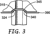
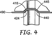
図3を参照すると、1つ以上のテーパ先端324の断面プロフィールは弓形部分340を含んでいる。図4を参照すると、1つ以上のテーパ先端424の断面プロフィールは傾斜部分440を含んでいる。ある実施形態において、先端の断面プロフィールは傾斜部分と弓形部分とを含んでいる。
With reference to FIG. 3, the cross-sectional profile of one or more
同様に、窪みテーパ開口部は、夫々、任意の形状を有していてよいが、一般的には、先端および窪みテーパ開口部がその間にある膜と係合するときに膜に気密封止を形成するために、係合するテーパ先端を補う形状となるように選択される。このように、図3に示す通り、窪みテーパ開口部315の断面プロフィールは、弓形部分345を含んでいてもよい。同様に、図4に示す通り、窪みテーパ開口部415の断面プロフィールは、傾斜部分445を含んでいてもよい。ある実施形態において、先端の断面プロフィールは傾斜部分と弓形部分との両方を含んでいてもよい。
Similarly, each of the recessed taper openings may have any shape, but in general, the membrane is hermetically sealed when the tip and recessed taper openings engage the film between them. In order to form, it is selected to have a shape that complements the tapered tip to engage. Thus, as shown in FIG. 3, the cross-sectional profile of the recessed
図3および4に示す通り、テーパ先端は、夫々、その間にある膜390または490を固定する窪みテーパ開口部と係合するよう構成されている。
As shown in FIGS. 3 and 4, the tapered tips are each configured to engage a recessed tapered opening that secures the
一般的に、窪みテーパ開口部およびテーパ先端の正確な形状は重要ではないが、本発明によるシステムを組み立てるときは、膜の穿孔を防止するために、窪みテーパ開口部の深さは、1、0.5、0.3、0.2未満さらに0.1センチメートル未満に、テーパの平均角度は周囲表面から45、30未満さらに20度未満に制限してもよい。 In general, the exact shape of the recessed taper opening and the tapered tip is not critical, but when assembling the system according to the invention, the depth of the recessed taper opening is 1, to prevent membrane perforation. Less than 0.5, 0.3, 0.2 and even less than 0.1 centimeters, the average angle of the taper may be limited to less than 45, 30 and even less than 20 degrees from the surrounding surface.
本発明に用いるファスニング手段(例えば、第1および第2のベースを留めるための手段、保持プレートを第2のベースに留める手段、カバーリング手段を第2のベースに留めるための手段および/またはカバープレートを第1のベースに留めるための手段)は取り外し可能であっても取り外し不可能であってもよい。有用なファスニング手段としては、機械、接着および引力(例えば、磁気、重力)手段が挙げられる。取り外し可能なファスニング手段としては、例えば、ネジ、除去可能な接着剤、クランプ、ステープル、クリップ、釘、ピン、フック・アンド・ループファスナー、重り、マッシュルームタイプメカニカルファスナー、スナップおよびこれらの組み合わせが挙げられる。取り外し不可能なファスニング手段としては、例えば、除去不可能な接着剤、リベット、溶接、ロッキングスナップコネクタ、はんだ継手およびこれらの組み合わせが挙げられる。 Fastening means used in the present invention (eg, means for fastening the first and second bases, means for fastening the retaining plate to the second base, means for fastening the covering means to the second base and / or cover) The means (for fastening the plate to the first base) may be removable or non-removable. Useful fastening means include mechanical, adhesive and attractive (eg, magnetic, gravity) means. Removable fastening means include, for example, screws, removable adhesives, clamps, staples, clips, nails, pins, hook and loop fasteners, weights, mushroom type mechanical fasteners, snaps and combinations thereof. . Non-removable fastening means include, for example, non-removable adhesives, rivets, welding, locking snap connectors, solder joints, and combinations thereof.
第1のベースと第2のベースの間に膜を位置決めしている間、膜は、一般的に、平滑化(例えば、手により)されて、適所に固定する(例えば、保持プレートをベースに留める、または2つのベースを併せて留めることにより)前に皺が取り去られる。 While positioning the membrane between the first base and the second base, the membrane is generally smoothed (eg, by hand) and secured in place (eg, holding plate to the base). The heel is removed before (by fastening or fastening the two bases together).
好適な膜は、例えば、合成ポリマー膜(例えば、酢酸セルロースシート、エチルセルロース、リン脂質、コレステロールおよび鉱油を含有するポリマー膜、ポリ(エチレングリコール)ブロックセグメントを含有するポリウレタンポリマー、ポリ(スチレン)に組み込まれた合成ゼオライト、シリコーンゴム、交互の親水性および親油性シートを含有するラミネートポリマーシート、有機液体を充填したろ紙または膜、ならびに培養細胞膜)、ヘアレスマウススキン、スネークスキン、ピッグスキンおよび移植用皮膚をはじめとする薄く柔らかく曲がりやすいシートであるのが一般的である。浸透試験において哺乳動物の皮膚の代替として有用な好適な合成膜に関する更なる詳細については、例えば、ホークら(Houk et al.)、「皮膚浸透調査のための膜モデル(Membrane Models for Skin Penetration Studies)」、ケミカルレビュー(Chemical Reviews)(1988年)、第88巻(3)、455−472ページ、およびハタナカら(Hatanaka et al.)、「ドラッグの皮膚浸透の予測II、皮膚代替物としての複合体膜の開発(Prediction of Skin Permeability of Drugs. II. Development of Composite Membrane as a Skin Alternative)」、製薬インターナショナルジャーナル(International Journal of Pharmaceutics)(1992年)、第79巻、21−28ページに記載されている。 Suitable membranes include, for example, synthetic polymer membranes (eg, cellulose acetate sheets, ethyl cellulose, polymer membranes containing phospholipids, cholesterol and mineral oil, polyurethane polymers containing poly (ethylene glycol) block segments, poly (styrene) Synthetic zeolite, silicone rubber, laminated polymer sheet containing alternating hydrophilic and lipophilic sheets, filter paper or membrane filled with organic liquid, and cultured cell membrane), hairless mouse skin, snake skin, pig skin and skin for transplantation In general, the sheet is thin, soft and easy to bend. For further details regarding suitable synthetic membranes useful as a substitute for mammalian skin in penetration tests, see, for example, Hawk et al., “Membrane Models for Skin Penetration Studies. ”, Chemical Reviews (1988), 88 (3), 455-472, and Hatanaka et al.,“ Prediction of skin penetration of drugs II, as a skin substitute ” II. Development of Composite Membrane as a Skin Alternati (Prediction of Skin Permeability of Drugs. II. Development of Composite Membrane as a Skin Alternati e) ", the pharmaceutical International journal (International Journal of Pharmaceutics) (1992 years), the first 79 volumes, are described in the 21-28 page.
本発明によるシステムは任意の配向で用いてよい。しかしながら、組み立てを促すためには、ベースを水平に配向して、キャビティを充填しシステムを組み立てるのが有用である。 The system according to the invention may be used in any orientation. However, to facilitate assembly, it is useful to orient the base horizontally to fill the cavity and assemble the system.
一般的な使用において、第1または第2のベースの一方は、評価される1種類以上の化合物(例えば、薬剤、賦形剤、染料、化学試薬およびこれらの混合物、栄養剤、ビタミン、コスモシューティカル(cosmoceuticals))を含む複数の組成物を含有する処方プレートとして、他方は受容プレートとして用いられる。例えば、第2のベースは処方プレートであり、第1のベースは受容プレート、またはこの逆である。 In general use, one of the first or second bases is one or more compounds to be evaluated (eg, drugs, excipients, dyes, chemical reagents and mixtures thereof, nutrients, vitamins, cosmoshoes The other is used as a prescription plate containing a plurality of compositions including cosmos and the other as a receiving plate. For example, the second base is a prescription plate and the first base is a receiving plate, or vice versa.
図5に示す例証のシステム500において、膜590は、処方プレート510に対して位置決めされて、処方プレート510の窪みテーパ開口部515(図示せず)をカバーする。穿孔部508を有する保持プレート506は、保持プレート506の孔517を通過して、処方プレート510のネジ孔518(図示せず)と係合されて、ネジ519により処方プレート510に留められ、これによってサブアセンブリ502が形成される。サブアセンブリ502は、処方プレート510の孔594を通過して、受容プレート550のネジ孔596と係合するネジ595により受容プレート550に留められる。本実施形態において、サブアセンブリ502は、膜590に触れずに、受容プレート550に繰り返し留めたり外したりすることができ有利である。
In the
膜590は、一般的に、平滑化(例えば、手により)されて、保持プレート506を処方プレート510に留める前に皺が取り去られる。評価される組成物(図示せず)は、処方プレート510の通路535に配置され、これはテープ537によりカバーされて、取扱いを促し、かつ/または蒸発を減少させる。テープ537は、例えば、カバープレートのようなその他のカバーリング手段と交換してもよい。
The
受容プレート550の中空突出部555にあるキャビティ570に受容液体(例えば、血清またはその合成版、図示せず)を充填する。誤った膜拡散速度につながる可能性のある、組み立て中の空隙の形成を排除するのを補助するために、キャビティ570に受容液体を、受容液体の表面張力が許す最大点まで過充填してもよい。処方プレート510および受容プレート550を併せて留めて、テーパ先端560が窪みテーパ開口部515と係合して、その間にある膜590を固定する。このプロセスの間、膜590は、一般的に、テーパ先端560の開口部570を通して伸張され、テーパ先端560と窪みテーパ開口部515の間で圧縮されて、気密封止が確実になされて、近接するセル間のクロストークの可能性を減少、より一般的には、排除する。中空突出部555の細長い本体部分556は、セルから漏れる液体を重力により無害に流して、例えば、中空突出部555が上方に垂直に延在するようにシステムを配向するとき、クロストークの防止を更に補助する。
A
本発明によるシステムは、キャビティ570が受容プレート550を通して延在している場合に存在する、例えば、図5に、テープ537および/またはカバープレート578により示される、1つ以上のカバーリング手段を更に含んでいてもよい。好適なカバーリング手段としては、例えば、フィルム、シーリングマット、プレート、ストッパーおよびこれらの組み合わせが挙げられる。カバーリング手段は、例えば、一体型カバーリング手段(例えば、フィルム、テープまたはカバープレート)または非一体型カバーリング手段(例えば、複数のフィルム、テープ、ストッパ、ゴム隔膜またはこれらの組み合わせ)としてよい。
The system according to the present invention further includes one or more covering means that are present when the
図6に示す他の例証のシステム600において、処方プレート650はテーパ先端660からなる中空突出部を有している。通路685(図示せず)は、処方プレート650を通して延在しており、テーパ先端660に開口部665を形成する。受容プレート610は、テーパ先端660と係合するよう構成された窪みテーパ開口部615を有している。キャビティ620は窪みテーパ開口部615と連続している。受容プレート610は、孔617を通過して、ネジ孔618と係合する保持ブラケット672およびネジ662により処方プレート650に留められて、テーパ先端660は窪みテーパ開口部615と係合して、その間にある膜690を固定する。キャビティ620の内容物の光学的な検出ができるよう、受容プレート610は光学的に透明であり、保持ブラケット672は適切な間隔および位置合せの穿孔部629を有している。
In another
光学的な検出方法としては、例えば、目視検査、分光法、光学スキャナ、ならびにビデオおよび写真による方法(デジタル写真による方法を含む)が挙げられる。 Optical detection methods include, for example, visual inspection, spectroscopy, optical scanners, and video and photo methods (including digital photo methods).
本発明によるシステムは、様々な公知の収集、自動分配装置および/または自動サンプリング装置と組み合わせて用いてよい。かかる装置としては、例えば、ウィスコンシン州ミドルトンのギルソン社(Gilson, Inc., Middleton, Wisconsin)より市販されているような液体ハンドリングロボット、および例えば、スイス、ラッパースヴィルのヴィードマンプラスチックステクノロジーAG(Weidmann Plastics Technology AG, Rapperswil, Switzerland)より入手可能なウェルプレート(例えば、24、96または384ウェルの)が例示される。 The system according to the present invention may be used in combination with various known collection, automatic dispensing and / or automatic sampling devices. Such devices include, for example, liquid handling robots such as those commercially available from Gilson, Inc., Middleton, Wisconsin, and Widman Plastics Technology AG (Rappersville, Switzerland). Illustrative are well plates (eg, 24, 96 or 384 wells) available from Weidmann Plastics Technology AG, Rapperswil, Switzerland.
本発明によるシステムは、組み立てて、またはキット形態(すなわち、組み立ててない、または部分的に組み立てた)で膜有り、または膜無しで提供してもよい。 The system according to the present invention may be provided with or without a membrane in assembled or kit form (ie, not assembled or partially assembled).
本発明の様々な予見されない修正および変更は、本発明の範囲および目的から逸脱することなしに当業者には明白であり、本発明はここに規定した説明のための実施形態に不当に限定されないことを理解するべきである。 Various unforeseen modifications and changes of the invention will be apparent to those skilled in the art without departing from the scope and purpose of the invention, and the invention is not unduly limited to the illustrative embodiments defined herein. You should understand that.
Claims (3)
第1および第2の対向する表面を有し、前記第1の表面が、前記複数の中空突出部と係合するよう構成され、第2のベース中へ延在している各キャビティと連続した、複数の窪みテーパ開口部を有する、第2のベースと、
中空突出部が通過できるよう構成された穿孔部を有する保持プレートであって、前記保持プレートが第2のファスニング手段により前記第2のベースに留められており、前記膜が前記第2のベースと前記保持プレートの間に配置されている、保持プレートと、
前記窪みテーパ開口部と前記中空突出部の前記先端部に接触する膜と、
を含み、前記第1のベースが第1のファスニング手段により前記第2のベースに留められており、a)中空突出部内の各キャビティは前記第1のベースを通して延在して、前記第1のベースの前記第2の表面に開口部を形成し、またはb)前記第2のベース内の各キャビティは前記第2のベースを通して延在して、前記第2のベースの前記第2の表面に開口部を形成し、またはc)中空突出部内の各キャビティは前記第1のベースを通して延在して、前記第1のベースの前記第2の表面に開口部を形成し、前記第2のベース内の各キャビティは前記第2のベースを通して延在して、前記第2のベースの前記第2の表面に開口部を形成する、膜を通して化合物の拡散を測定するシステム。A first and second opposing surfaces; a plurality of hollow protrusions extending outward from the first surface, wherein a tapered tip having an opening; and the protrusion disposed within the protrusion A first base having a hollow protrusion having an opening and each continuous cavity;
Having first and second opposing surfaces, wherein the first surface is configured to engage the plurality of hollow protrusions and is continuous with each cavity extending into the second base; A second base having a plurality of recessed taper openings;
A holding plate having a perforated portion configured to allow a hollow protrusion to pass through, wherein the holding plate is fastened to the second base by a second fastening means, and the membrane is connected to the second base. A holding plate disposed between the holding plates;
A membrane in contact with the recess taper opening and the tip of the hollow protrusion;
Wherein the first base is fastened to the second base by first fastening means, and a) each cavity in the hollow projection extends through the first base, the first base Forming an opening in the second surface of the base, or b) each cavity in the second base extends through the second base and into the second surface of the second base. Forming an opening; or c) each cavity in the hollow protrusion extends through the first base to form an opening in the second surface of the first base, and the second base. A system for measuring compound diffusion through a membrane, wherein each cavity extends through the second base to form an opening in the second surface of the second base.
前記第1のベースの少なくとも1つのキャビティ中に第1の流体組成物を配置する工程と、
前記第2のベースの少なくとも1つのキャビティ中に化合物を含む第2の流体組成物を配置する工程と、
前記第1の流体組成物の前記化合物含量を分析する工程と、
を含み、前記第1および第2のベースの前記キャビティが膜を介して流体連通している、膜を通した化合物の拡散を測定する方法。Providing the system of claim 1 ;
Disposing a first fluid composition in at least one cavity of the first base;
Disposing a second fluid composition comprising a compound in at least one cavity of the second base;
Analyzing the compound content of the first fluid composition;
And measuring the diffusion of the compound through the membrane, wherein the cavities of the first and second bases are in fluid communication through the membrane.
第1および第2の対向する表面を有し、前記第1の表面が、前記複数の中空突出部と係合するよう構成され、第2のベース中へ延在している各キャビティと連続した、複数の窪みテーパ開口部を有する、第2のベースと、
中空突出部が通過できるよう構成された穿孔部を有する保持プレートと、
前記第2のベースに前記保持プレートを留める手段と、
前記第1のベースを前記第2のベースに留める手段と、
を含み、a)中空突出部内の各キャビティは前記第1のベースを通して延在して、前記第1のベースの前記第2の表面に開口部を形成し、またはb)前記第2のベース内の各キャビティは前記第2のベースを通して延在して、前記第2のベースの前記第2の表面に開口部を形成し、またはc)中空突出部内の各キャビティは前記第1のベースを通して延在して、前記第1のベースの前記第2の表面に開口部を形成し、前記第2のベース内の各キャビティは前記第2のベースを通して延在して、前記第2のベースの前記第2の表面に開口部を形成する、膜を保持する、キットの形態にあるシステム。A first and second opposing surfaces; a plurality of hollow protrusions extending outward from the first surface, wherein a tapered tip having an opening; and the protrusion disposed within the protrusion A first base having a hollow protrusion having an opening and each continuous cavity;
Having first and second opposing surfaces, wherein the first surface is configured to engage the plurality of hollow protrusions and is continuous with each cavity extending into the second base; A second base having a plurality of recessed taper openings;
A holding plate having a perforated portion configured to allow the hollow protrusion to pass through;
Means for fastening the retaining plate to the second base;
Means for fastening the first base to the second base;
A) each cavity in the hollow projection extends through the first base to form an opening in the second surface of the first base, or b) in the second base Each cavity extends through the second base to form an opening in the second surface of the second base, or c) each cavity in the hollow projection extends through the first base. An opening is formed in the second surface of the first base, and each cavity in the second base extends through the second base, and the second base A system in the form of a kit that retains a membrane that forms an opening in a second surface.
Applications Claiming Priority (2)
| Application Number | Priority Date | Filing Date | Title |
|---|---|---|---|
| US10/669,276 US7635452B2 (en) | 2003-09-24 | 2003-09-24 | System, kit, and method for measuring membrane diffusion |
| PCT/US2004/024487 WO2005036138A1 (en) | 2003-09-24 | 2004-07-28 | System, kit, and method for measuring membrane diffusion |
Publications (3)
| Publication Number | Publication Date |
|---|---|
| JP2007506970A JP2007506970A (en) | 2007-03-22 |
| JP2007506970A5 JP2007506970A5 (en) | 2007-09-13 |
| JP4317224B2 true JP4317224B2 (en) | 2009-08-19 |
Family
ID=34313693
Family Applications (1)
| Application Number | Title | Priority Date | Filing Date |
|---|---|---|---|
| JP2006527975A Expired - Fee Related JP4317224B2 (en) | 2003-09-24 | 2004-07-28 | System, kit and method for measuring membrane diffusion |
Country Status (4)
| Country | Link |
|---|---|
| US (1) | US7635452B2 (en) |
| EP (1) | EP1664733A1 (en) |
| JP (1) | JP4317224B2 (en) |
| WO (1) | WO2005036138A1 (en) |
Families Citing this family (21)
| Publication number | Priority date | Publication date | Assignee | Title |
|---|---|---|---|---|
| US20060154378A1 (en) * | 2005-01-13 | 2006-07-13 | Yabin Lei | Method for measuring the leaching of encapsulated material into application media |
| DE102005057031B4 (en) * | 2005-11-25 | 2011-04-21 | Innovent E.V. Technologieentwicklung | Device for permeation or mass transfer studies |
| FR2951089B1 (en) * | 2009-10-09 | 2013-07-05 | Univ Franche Comte | DIFFUSION INSERT FOR MEMBRANE ANALYSIS, KIT-CELL-UNIT AND DIFFUSION METHOD |
| DE102009052673A1 (en) * | 2009-11-12 | 2011-05-19 | Nanoanalytics Gmbh | Device for determining the impedance of cell layers |
| CN102141504B (en) * | 2011-01-27 | 2013-06-12 | 中国商用飞机有限责任公司 | Testing device and method for testing gas penetration rate in thickness direction of overlay |
| CN102183444B (en) * | 2011-01-27 | 2013-09-25 | 中国商用飞机有限责任公司 | Device and method for testing gas permeability in inner direction of paving layer surface |
| FR2981156B1 (en) * | 2011-10-10 | 2014-05-30 | Univ Claude Bernard Lyon | DEVICE FOR STUDIING THE PERMEABILITY OF BIOLOGICAL, ARTIFICIAL OR SYNTHETIC MEMBRANES |
| ITRM20130163A1 (en) * | 2013-03-18 | 2014-09-19 | Univ Roma | DEVICES AND METHOD FOR TESTING THIN FILMS AND STRIPS |
| CN103308564A (en) * | 2013-06-03 | 2013-09-18 | 拉芳家化股份有限公司 | Method for detecting percutaneous absorption efficiency of active component of cosmetic |
| JP6418711B2 (en) * | 2014-05-19 | 2018-12-05 | 株式会社イントロテック | Permeability test equipment |
| JP6533239B2 (en) * | 2014-08-06 | 2019-06-19 | ヘクサル・アクチェンゲゼルシャフトHexal AG | Method and apparatus for determining the disintegration time of a film-like pharmaceutical dosage form |
| EP3356791B1 (en) * | 2015-10-01 | 2019-07-31 | Galderma Research & Development | Diffusion cell and uses for evaluating the diffusion of a compound through a membrane |
| FR3042037A1 (en) * | 2015-10-01 | 2017-04-07 | Galderma Res & Dev | DIFFUSION CELL AND USES FOR EVALUATING DIFFUSION OF A COMPOUND THROUGH A MEMBRANE |
| US10613011B2 (en) * | 2016-03-14 | 2020-04-07 | Creighton University | Diffusion cells and related methods |
| FR3054144B1 (en) * | 2016-07-20 | 2021-01-01 | Inst De Radioprotection Et De Surete Nucleaire | THIN LAYER DIFFUSION GRADIENT DEVICE AND FOCUSING DEVICE FOR SUCH A DEVICE |
| US10883978B2 (en) | 2017-01-31 | 2021-01-05 | Agilent Technologies, Inc. | Method and device for calibration of biological flux |
| GB2559991A (en) * | 2017-02-23 | 2018-08-29 | Medherant Ltd | Diffusion test system |
| CN107389523B (en) * | 2017-07-06 | 2020-02-18 | 中国农业科学院农业资源与农业区划研究所 | Method and system for measuring maximum aperture of coated fertilizer controlled release membrane |
| WO2020037194A1 (en) * | 2018-08-17 | 2020-02-20 | Sierra Biosystems, Inc. | Row-independent oligonucleotide synthesis |
| US11181460B1 (en) * | 2019-06-20 | 2021-11-23 | The United States Of America As Represented By The Secretary Of The Army | Apparatus and method for measuring permeation of contaminants through a complex protective material swatch |
| US20210072231A1 (en) * | 2019-09-09 | 2021-03-11 | Board Of Regents, The University Of Texas System | Methods and apparatus for high-throughput screening for testing permeability and retention of compounds across biological barriers |
Family Cites Families (9)
| Publication number | Priority date | Publication date | Assignee | Title |
|---|---|---|---|---|
| US4511534A (en) * | 1982-05-26 | 1985-04-16 | John T. Bennett | Liquid transfer device |
| US5591636A (en) * | 1993-10-18 | 1997-01-07 | Precision Instrument Design | Membrane holder |
| US5490415A (en) | 1994-04-15 | 1996-02-13 | Pharmetrix Corporation | Diffusion test apparatus and method |
| US5962250A (en) | 1997-10-28 | 1999-10-05 | Glaxo Group Limited | Split multi-well plate and methods |
| US6521191B1 (en) | 1999-07-07 | 2003-02-18 | Novosis Ag | Permeation cell for in vitro determination of skin permeation of pharmaceutical drugs |
| US6455007B1 (en) | 2000-06-13 | 2002-09-24 | Symyx Technologies, Inc. | Apparatus and method for testing compositions in contact with a porous medium |
| US6439036B1 (en) | 2000-06-13 | 2002-08-27 | Symyx Technologics, Inc. | Method for evaluating a test fluid |
| ES2273873T3 (en) | 2000-07-14 | 2007-05-16 | Transform Pharmaceuticals, Inc. | SYSTEM AND PROCEDURE FOR OPTIMIZATION OF THE TRANSFER OF COMPOUNDS THROUGH A FABRIC BARRIER. |
| AU2001286725A1 (en) | 2000-08-23 | 2002-03-04 | The Regents Of The University Of California | A combinatorial method for rapid screening of drug delivery formulations |
-
2003
- 2003-09-24 US US10/669,276 patent/US7635452B2/en not_active Expired - Fee Related
-
2004
- 2004-07-28 EP EP04757380A patent/EP1664733A1/en not_active Withdrawn
- 2004-07-28 JP JP2006527975A patent/JP4317224B2/en not_active Expired - Fee Related
- 2004-07-28 WO PCT/US2004/024487 patent/WO2005036138A1/en active Application Filing
Also Published As
| Publication number | Publication date |
|---|---|
| EP1664733A1 (en) | 2006-06-07 |
| US20050063862A1 (en) | 2005-03-24 |
| US7635452B2 (en) | 2009-12-22 |
| JP2007506970A (en) | 2007-03-22 |
| WO2005036138A1 (en) | 2005-04-21 |
Similar Documents
| Publication | Publication Date | Title |
|---|---|---|
| JP4317224B2 (en) | System, kit and method for measuring membrane diffusion | |
| US5284753A (en) | Multiple-site chemotactic test apparatus and method | |
| CN100354626C (en) | Device for measuring the electrical activity of biological elements and its applications | |
| US8465696B2 (en) | Dry test strip with controlled flow and method of manufacturing same | |
| US9687844B2 (en) | Liquid specimen cup including movable caddy and translucent adulteration panel | |
| US8058073B2 (en) | Immunodiagnostic test cards having indicating indicia | |
| AU733985B2 (en) | Analytic test element with a capillary channel | |
| US5210021A (en) | Multiple-site chemotactic test apparatus and method | |
| ES2643836T3 (en) | Disposable chamber to analyze biological fluids | |
| DK2590743T3 (en) | Chip unit for use in a mikrofluidanalysesystem | |
| CA2559453A1 (en) | Methods and apparatus for integrated cell handling and measurements | |
| AU2002253388A1 (en) | Assay system | |
| JPH07198715A (en) | Production of sensor and sensor manufactured by method thereof | |
| CA2473390C (en) | Crystal forming apparatus and method for using same | |
| US8307531B2 (en) | Apparatus and method of manufacturing bodily fluid test strip | |
| WO2005121307A2 (en) | Gas control in a microreactor | |
| EA017587B1 (en) | Method and apparatus for monitoring spatial fibrin clot formation | |
| JPH06207934A (en) | Cuvette matrix | |
| EP1974818A1 (en) | Device and method for use in analysis | |
| US20190001332A1 (en) | Disposable independent 3-d structure depened sequential capillary lateral flow device for analyte determination | |
| US20150219597A1 (en) | Method of manufacturing an electrophoresis cassette | |
| WO2017058788A1 (en) | Systems and methods for a lateral flow test strip holder | |
| JP3669996B2 (en) | Locating pins for multiwell test equipment | |
| EP3948254A1 (en) | Methods and apparatus for performing sample measurements using visible light on samples manipulated with acoustic waves | |
| US20150177186A1 (en) | Electrophoresis gel unit comprising a flat gel member attached to a support |
Legal Events
| Date | Code | Title | Description |
|---|---|---|---|
| A521 | Written amendment |
Free format text: JAPANESE INTERMEDIATE CODE: A523 Effective date: 20070725 |
|
| A621 | Written request for application examination |
Free format text: JAPANESE INTERMEDIATE CODE: A621 Effective date: 20070725 |
|
| A977 | Report on retrieval |
Free format text: JAPANESE INTERMEDIATE CODE: A971007 Effective date: 20090331 |
|
| TRDD | Decision of grant or rejection written | ||
| A01 | Written decision to grant a patent or to grant a registration (utility model) |
Free format text: JAPANESE INTERMEDIATE CODE: A01 Effective date: 20090421 |
|
| A01 | Written decision to grant a patent or to grant a registration (utility model) |
Free format text: JAPANESE INTERMEDIATE CODE: A01 |
|
| A61 | First payment of annual fees (during grant procedure) |
Free format text: JAPANESE INTERMEDIATE CODE: A61 Effective date: 20090521 |
|
| R150 | Certificate of patent or registration of utility model |
Free format text: JAPANESE INTERMEDIATE CODE: R150 |
|
| FPAY | Renewal fee payment (event date is renewal date of database) |
Free format text: PAYMENT UNTIL: 20120529 Year of fee payment: 3 |
|
| LAPS | Cancellation because of no payment of annual fees |