JP4315577B2 - Opening device and flexible member exercise device - Google Patents
Opening device and flexible member exercise device Download PDFInfo
- Publication number
- JP4315577B2 JP4315577B2 JP2000173401A JP2000173401A JP4315577B2 JP 4315577 B2 JP4315577 B2 JP 4315577B2 JP 2000173401 A JP2000173401 A JP 2000173401A JP 2000173401 A JP2000173401 A JP 2000173401A JP 4315577 B2 JP4315577 B2 JP 4315577B2
- Authority
- JP
- Japan
- Prior art keywords
- braking force
- braking
- state
- shielding function
- flexible member
- Prior art date
- Legal status (The legal status is an assumption and is not a legal conclusion. Google has not performed a legal analysis and makes no representation as to the accuracy of the status listed.)
- Expired - Fee Related
Links
Images


Description
【0001】
【発明の属する技術分野】
本発明は、開口部を遮蔽するための開口部装置、及び、可撓性部材を双方向に走行かつ停止可能な可撓性部材運動装置に関するものである。
【0002】
【従来の技術】
例えば、建物や車両や船舶などの開口部を遮蔽するための開口部装置は、それが担当する遮蔽機能の種類は少ない(概ね1個である)。
【0003】
例えば、窓は、開放時には通風機能をも担っているが、閉鎖時には外光を屋内に取り込む機能を担っている。また、ブラインドは、屋内に取り込む外光の量の制御機能を担っている。さらに、網戸は、虫が屋内へ入ることを防止しつつ通風機能を担っている。
【0004】
【発明が解決しようとする課題】
しかしながら、従来の開口部装置は、上述のように、担当している機能の種類が少ないため、多くの機能が求められる場合には、異なる機能を担う複数の開口部装置を開口部に並設しなければならない。例えば、上述したように、窓の側には、ブラインドや網戸も設けられる。
【0005】
本発明は、以上の点を考慮してなされたものであり、1装置で開口部に関連した多くの遮蔽機能を実現可能な開口部装置を提供しようとするものである。
【0006】
また、このような開口部装置に適用するのに好適な可撓性部材運動装置を提供しようとするものである。
【0007】
【課題を解決するための手段】
かかる課題を解決するため、第1の本発明による開口部装置は、(1)開口部を遮蔽する位置に位置したときの遮蔽機能が異なる複数種類の遮蔽機能領域を往復動方向に、各種類について少なくとも1個ずつ並設した遮蔽機能部材と、(2)上記遮蔽機能部材を往動させる際に駆動軸となる第1の主軸と、(3)上記遮蔽機能部材を復動させる際に駆動軸となる第2の主軸と、(4)電源供給を受けて、上記第1の主軸に駆動力を与える第1の駆動源と、(5)電源供給を受けて、上記第2の主軸に駆動力を与える第2の駆動源と、(6)上記第1の主軸が駆動されている少なくとも一部の期間に、上記遮蔽機能部材の往動を妨げるように、上記第2の主軸又はその近傍位置の上記遮蔽機能部材の部分に制動力を付与する、電気的に制動力が制御可能な第1の制動機構と、(7)上記第2の主軸が駆動されている少なくとも一部の期間に、上記遮蔽機能部材の復動を妨げるように、上記第1の主軸又はその近傍位置の上記遮蔽機能部材の部分に制動力を付与する、電気的に制動力が制御可能な第2の制動機構と、(8)上記遮蔽機能部材を往動させたり、復動させたり、停止させたりする必要が生じたときに、上記第1及び又は第2の駆動源、並びに、上記第1及び又は第2の制動機構の動作を制御する制御手段とを備え、(9)上記第1及び第2の制動機構は、少なくとも、制動力がない状態、制動力が弱い状態、制動力が強い状態を取り得るものであり、(10)上記制御手段は、(11−1)上記遮蔽機能部材を往動させる際において、往動開始時、上記第1の制動機構を制動力がない状態にすると共に、上記第2の制動機構を制動力が弱い状態に設定し、上記第1の駆動源を始動させ、経過タイマの計時時間に基づいた加速制御を行い、経過タイマの計時時間が加速制御から定速走行に切り換えるタイミングを規定する所定時間になると定速走行に切り換え、上記遮蔽機能部材が減速開始位置へ到達すると、上記第2の制動機構を制動力が強い状態に切り換えると共に、上記第1の駆動源に対する減速制御を行い、上記遮蔽機能部材が停止位置へ到達すると、上記第1の駆動源を停止させると共に、第2の制動機構を制動力がない状態にし、(11−2)上記遮蔽機能部材を復動させる際において、復動開始時、上記第2の制動機構を制動力がない状態にすると共に、上記第1の制動機構を制動力が弱い状態に設定し、上記第2の駆動源を始動させ、経過タイマの計時時間に基づいた加速制御を行い、経過タイマの計時時間が加速制御から定速走行に切り換えるタイミングを規定する所定時間になると定速走行に切り換え、上記遮蔽機能部材が減速開始位置へ到達すると、上記第1の制動機構を制動力が強い状態に切り換えると共に、上記第2の駆動源に対する減速制御を行い、上記遮蔽機能部材が停止位置へ到達すると、上記第2の駆動源を停止させると共に、第1の制動機構を制動力がない状態にすることを特徴とする。
【0009】
また、第2の本発明による可撓性部材運動装置は、(1)往復動可能な少なくとも一部がシート状となっている可撓性部材と、(2)上記可撓性部材を往動させる際に駆動軸となる第1の主軸と、(3)上記可撓性部材を復動させる際に駆動軸となる第2の主軸と、(4)電源供給を受けて、上記第1の主軸に駆動力を与える第1の駆動源と、(5)電源供給を受けて、上記第2の主軸に駆動力を与える第2の駆動源と、(6)上記第1の主軸が駆動されている少なくとも一部の期間に、上記可撓性部材の往動を妨げるように、上記第2の主軸又はその近傍位置の上記可撓性部材の部分に制動力を付与する、電気的に制動力が制御可能な第1の制動機構と、(7)上記第2の主軸が駆動されている少なくとも一部の期間に、上記可撓性部材の復動を妨げるように、上記第1の主軸又はその近傍位置の上記可撓性部材の部分に制動力を付与する、電気的に制動力が制御可能な第2の制動機構と、(8)上記可撓性部材を往動させたり、復動させたり、停止させたりする必要が生じたときに、上記第1及び又は第2の駆動源、並びに、上記第1及び又は第2の制動機構の動作を制御する制御手段とを備え、(9)上記第1及び第2の制動機構は、少なくとも、制動力がない状態、制動力が弱い状態、制動力が強い状態を取り得るものであり、(10)上記制御手段は、(11−1)上記可撓性部材を往動させる際において、往動開始時、上記第1の制動機構を制動力がない状態にすると共に、上記第2の制動機構を制動力が弱い状態に設定し、上記第1の駆動源を始動させ、経過タイマの計時時間に基づいた加速制御を行い、経過タイマの計時時間が加速制御から定速走行に切り換えるタイミングを規定する所定時間になると定速走行に切り換え、上記可撓性部材が減速開始位置へ到達すると、上記第2の制動機構を制動力が強い状態に切り換えると共に、上記第1の駆動源に対する減速制御を行い、上記可撓性部材が停止位置へ到達すると、上記第1の駆動源を停止させると共に、第2の制動機構を制動力がない状態にし、(11−2)上記可撓性部材を復動させる際において、復動開始時、上記第2の制動機構を制動力がない状態にすると共に、上記第1の制動機構を制動力が弱い状態に設定し、上記第2の駆動源を始動させ、経過タイマの計時時間に基づいた加速制御を行い、経過タイマの計時時間が加速制御から定速走行に切り換えるタイミングを規定する所定時間になると定速走行に切り換え、上記可撓性部材が減速開始位置へ到達すると、上記第1の制動機構を制動力が強い状態に切り換えると共に、上記第2の駆動源に対する減速制御を行い、上記可撓性部材が停止位置へ到達すると、上記第2の駆動源を停止させると共に、第1の制動機構を制動力がない状態にすることを特徴とする。
【0010】
【発明の実施の形態】
(A)第1の実施形態
(A−1)第1の実施形態の構成
以下、本発明による開口部装置及び可撓性部材運動装置の第1の実施形態を、図面を参照しながら詳述する。なお、この第1の実施形態の開口部装置は、可撓性部材運動装置を含んで構成されている。
【0011】
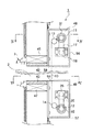
図2は、この第1の実施形態の開口部装置1の要部構成を取り出して示す概略斜視図である。図1は、図2におけるI−I線方向の縦断面図であり、図2に示した構成要素以外の構成要素をも示している。図3は、図1における上側のブラケット部の正面図(後述する屋内側から見た正面図である。図4は、図1におけるIV−IV線断面図であり、図5は、図1におけるV−V線断面図である。
【0012】
この第1の実施形態の開口部装置1は、図1、図4及び図5に示すように、屋内及び屋外を連通させる開口部2の屋内側を遮蔽するものとして設けられている。なお、屋外側にはサッシ3が設けられているが、サッシ3については、この第1の実施形態の特徴と無関係であるので、これ以上の説明は省略する。
【0013】
開口部装置1は、図2に示すように、シート状部材10、上側巻取軸11、下側巻取軸12、上側ガイドローラ13及び下側ガイドローラ14を主たる構成要素としている。
【0014】
シート状部材10は、後述するように、遮蔽対象の開口部2の上下方向の長さより十分に長く、その長手方向の一端は上側巻取軸11に取り付けられ、他端は下側巻取軸12に取り付けられており、上側巻取軸11及び下側巻取軸12の双方に巻回されている。上側巻取軸11から引き出されているシート状部材10の部分は、上側巻取軸11に近接して設けられている上側ガイドローラ13によって鉛直方向に沿うように方向が変換されており、下側巻取軸12から引き出されているシート状部材10の部分も、下側巻取軸11に近接して設けられている下側ガイドローラ14によって鉛直方向に沿うように方向が変換されている。すなわち、上側ガイドローラ13及び下側ガイドローラ14間の、シート状部材10の開口部2を遮蔽している部分の位置が常時同じ位置になるようになされている。
【0015】
上側巻取軸11は、シート状部材10を上動させる際の駆動軸として機能するものであり、一方、下側巻取軸12は、シート状部材10を下動させる際の駆動軸として機能するものである。
【0016】
上側巻取軸11の一端部(例えば屋内側からみて右端部)側には、一対のスプロケット15及び16並びにチェーン17でなる運動伝達機構(ベルト及びプーリでなるような他の運動伝達機構でも良い)を介して、モータ(上側モータ)18の駆動力が伝達されるようになされている。
【0017】
一方、上側巻取軸11の他端部(例えば屋内側からみて左端部)側は、一対のスプロケット19及び20並びにチェーン21でなる運動伝達機構(ベルト及びプーリでなるような他の運動伝達機構でも良い)を介して、電気的に制動力を可変し得るブレーキ22に連結されており、このブレーキ22によって、上側巻取軸11の回転を抑制可能になされている。
【0018】
同様に、下側巻取軸12の一端部(例えば屋内側からみて右端部)側には、一対のスプロケット23及び24並びにチェーン25でなる運動伝達機構を介して、モータ(下側モータ)26の駆動力が伝達されるようになされている。
【0019】
また、下側巻取軸12の他端部(例えば屋内側からみて左端部)側は、一対のスプロケット27及び28並びにチェーン29でなる運動伝達機構を介して、電気的に制動力を可変し得るブレーキ30に連結されており、このブレーキ30によって、下側巻取軸12の回転を抑制可能になされている。
【0020】
上側巻取軸11及び下側巻取軸12のそれぞれの、少なくともモータ18、26との連結端部側には、シート状部材10の幅方向の位置を規制する幅方向位置規制円板31、32が設けられている。
【0021】
なお、上側巻取軸11及び下側巻取軸12の他端側にも、幅方向位置規制円板が設けられていても良く、上側ガイドローラ13や下側ガイドローラ14にも、幅方向位置規制円板が設けられていても良い。
【0022】
上側巻取軸11や下側巻取軸12、上側ガイドローラ13や下側ガイドローラ14は、その設置位置が上か下かの相違があるが、同一部材を適用することができ、仮に、それに対するモータ18、26やブレーキ22、30も上下の違いに関係なく、同一部材を適用しようとすると(例えばこれら部材をユニット化すると)、第1の実施形態とは異なって、上側モータ18を屋内側から見て「右側」に設けたならば、下側モータ26を屋内側から見て「左側」に設けることを要する。
【0023】
しかしながら、この第1の実施形態では、上述したように上側モータ18及び下側モータ26を同一サイドに設けている。これは、シート状部材10を上動させている際でも下動させている際でも、その進行方向が鉛直方向に正しく沿って、僅かな蛇行や斜行をも防止しようとしたためである。以下、上側モータ18及び下側モータ26を同一サイドに設けると、シート状部材10の僅かな蛇行や斜行を防止できることを説明する。
【0024】
開口部2の上下方向の長さは、例えば1〜3m程度であり、上側巻取軸11及び下側巻取軸12間の距離もそれに応じているので、かなりの距離をシート状部材10が走行することとなる。このような場合において、幅方向の位置を規制する、意図した構成や方法を適用しなければ、シート状部材10の蛇行や斜行が生じることもあり得る。
【0025】
本願発明者は、試作や耐久性実験などを繰り返すうちに、巻取軸(11や12)を回転させていくと、その駆動力が導入されている端部側(モータが設けられている端部側に)に、巻取軸(11や12)におけるシート状部材10の幅方向の位置がごく僅かずつではあるがスライドしていくことを発見した。巻取軸(11や12)が剛性体でできているとはいえ、微視的に見た場合には、駆動力が導入されている端部側が先に進んでいるねじれが生じており、シート状部材10に対する引張ベクトルが、意図している進行方向のベクトル成分だけでなく、駆動力が導入されている端部側に向かうベクトル成分をも有するためと考えられる。
【0026】
以上のような駆動力が導入されている端部側(モータが設けられている端部側に)にシート状部材10の幅方向の位置がスライドしていく性質を考慮すると、上下のモータ18及び26を異なるサイドに設けた場合には、上動と下動でスライド方向が異なるので、斜行が生じやすく、シート状部材10の材質の均一性によっては蛇行も生じやすい。
【0027】
これに対して、この第1の実施形態のように、上下のモータ18及び26を同一のサイドに設けた場合には、上動と下動でスライドしようとする方向が同じになり、そのスライド方向のベクトル成分を、幅方向位置規制円板31、32からの抗力で相殺することにより、上動時及び下動時の双方共に、シート状部材10を意図した方向にのみ走行させることができ、蛇行や斜行を防止することができる。
【0028】
ブレーキ22及び30はそれぞれ、基本的には、自己が連結されている上側巻取軸11又は下側巻取軸12の他方の下側巻取軸12又は上側巻取軸11が、シート状部材10を走行させるための駆動軸になっているときに、後述する制御手段95(図7参照)によって制動力が制御されるものであり、これにより、シート状部材10の走行時のテンションが制御されるようになされている。
【0029】
このテンション制御機能により、シート状部材10の走行時の波打ちなどを防止することができる。
【0030】
開口部2は、左右上下の木枠40、41、42、43によって規定されている。左右の木枠40、41はそれぞれ、柱44、45に設けられており、上下の木枠42、43はそれぞれ、梁46、47に設けられている。
【0031】
屋内側から見て右側の柱45の開口部2より高い位置及び低い位置のそれぞれには、L字状のブラケット48、49の一面が、他面が鉛直方向に沿って延長すると共に屋内に向かって張り出すように、ビスや釘などによって取り付けられている。同様に、屋内側から見て左側の柱44の開口部2より高い位置及び低い位置のそれぞれにも、L字状のブラケット50、51(なお、ブラケット51はいずれの図面にも表記されていない)の一面が、他面が鉛直方向に沿って延長すると共に屋内に向かって張り出すように、ビスや釘などによって取り付けられている。
【0032】
上側の一対のブラケット48及び50の対向する張り出し面の内面のそれぞれには、上側巻取軸11の右、左の端縁を回転可能に支持するベアリング52、53と、上側ガイドローラ13の右、左の端縁を回転可能に支持するベアリング54、55とが設けられている。同様に、図示は省略されているが、下側の一対のブラケット49及び51の対向する張り出し面の内面のそれぞれには、下側巻取軸12の右、左の端縁を回転可能に支持するベアリングと、下側ガイドローラ14の右、左の端縁を回転可能に支持するベアリングとが設けられている。
【0033】
上側巻取軸11、上側ガイドローラ13、スプロケット15、16、チェーン17、モータ18、スプロケット19、20、チェーン21、ブラケット48、50などの上側の構成要素は、上側ケース56によって被覆されており、この上側ケース56は、ビスや釘などによって、柱44や45に固定されている。
【0034】
同様に、下側巻取軸12、下側ガイドローラ14、スプロケット22、23、チェーン24、モータ25、スプロケット26、27、チェーン28、ブラケット49、51などの下側の構成要素は、下側ケース57によって被覆されており、この下側ケース57も、ビスや釘などによって、柱44や45に固定されている。
【0035】
なお、上側ケース56の下面にはスリット58が設けられており、このスリット58を、シート状部材10が通っている。同様に、下側ケース57の上面にはスリット59が設けられており、このスリット59を、シート状部材10が通っている。
【0036】
開口部2の左右の柱44、45の屋内面にはそれぞれ、上側ケース56の下部から下側ケース57の上部までの間を上下方向に延びるガイドレール60、61(図5参照)が設けられている。各ガイドレール60、61のそれぞれの内部には、ブラシ状の一対のモヘア部材62及び63、64及び65が設けられており、各一対のモヘア部材62及び63、64及び65がそれぞれ、シート状部材10の左端や右端を案内する。
【0037】
ブラシ状のモヘア部材62、63、64及び65を適用しているのは、シート状部材10の走行時にシート状部材10を傷つけたりすることを防止しつつ案内させるためである。また、モヘア部材62、63、64及び65は、遮音、断熱、防虫、遮光などのシール効果を発揮すると共に、シート状部材10の風によるばたつき(従って、ばたつきによる音)を防止する。
【0038】
なお、ガイドレール60、61にモヘア部材62、63、64及び65を設けたものを示したが、上側ケース56のシート状部材10を外部に通すためのスリット58や、下側ケース57のシート状部材10を外部に通すためのスリット59にも、上述した機能を担うモヘア部材(その延長方向はシート状部材10の幅方向)を設けるようにしても良い。
【0039】
因みに、上述したような蛇行や斜行の防止機能や走行時の波打ちの防止機能などがない場合には、ガイドレール60、61が設けられていてもシート状部材10の左端や右端がガイドレール60、61からはみ出す恐れもある。
【0040】
また、これらガイドレール60及び61を、電気配線の引き回し部として併用するようにしても良い。
【0041】
図6は、シート状部材10を装置から取り外して引き延ばした状態を示す平面図である。
【0042】
シート状部材10は、図6に示すように、遮蔽対象の開口部2の面積及び形状にほぼ等しい面積及び形状を有する複数(図6では4個)の遮蔽機能領域70−1〜70−4を、長手方向に配設した構成を有する。シート状部材10の上端及び下端にはそれぞれ、上側巻取軸11及び下側巻取軸12との取り付けしろとしての捨て巻き部71U及び71Dが設けられている。また、各遮蔽機能領域間は、遮蔽機能領域を明確に区画すると共に、遮蔽機能領域を構成するシートを貼付したりする際のマージンとして機能する連結部72−1、72−2、72−3が設けられている。
【0043】
各遮蔽機能領域70−1、…、70−4は、自己が開口部2を遮蔽する位置に位置した際の機能が異なっている。ここで、完成前のシート状部材(シート基材)として、各遮蔽機能領域の位置が透孔になっているものを用意し、遮蔽機能が異なるシートを各遮蔽機能領域の位置の透孔を塞ぐように張り付けるなどして、シート状部材10を完成させても良い。また、完成前のシート状部材(シート基材)として、全体が透光性の1枚のシートでなるものを用意し、遮蔽機能が異なるシートを各遮蔽機能領域の位置に重ねて張り付けるなどして、シート状部材10を完成させても良い。さらに、シート基材に対して印刷処理や部分的な穴あけ処理を施してシート状部材10を完成させても良い。さらにまた、各遮蔽機能領域としてのシート部分をそれぞれ用意し、シート部分を長手方向に接合させていくことで、シート状部材10を完成させても良い。
【0044】
シート状部材10の一例として、遮蔽機能領域70−1が遮光シートでなり、遮蔽機能領域70−2が障子紙でなり、遮蔽機能領域70−3が網でなり、遮蔽機能領域70−4が完全透孔でなるものを挙げることができる。
【0045】
この第1の実施形態のように、屋外側にサッシ3が設けられている場合には、サッシ3の操作を考慮すると、遮蔽機能領域として完全透孔でなるものを用意しておくことは有用である。
【0046】
遮蔽機能領域70−iの遮蔽機能は、上記のものに限定されない。例えば、遮光量が異なるものを複数設けても良く、遮音、断熱、目隠しなどの遮蔽機能を担うものであっても良く、さらには、絵模様や文字模様などの美術的な背景を提供するものであっても良い。この観点からの変形例については、さらに詳細に説明する。
【0047】
シート状部材10の右端及び左端(一方の端部だけでも良い)には、遮蔽機能領域の位置管理などに利用される複数のマーク73R及び73Lが付されている。マーク73R及び73Lは、バーコードなどの位置を示すコードデータであっても良いが、ここでは単に光の透過を阻止するものとする。なお、マーク73R及び73L以外のシート状部材10の右端及び又は左端の領域は透光性のものとする。また、マーク73Rが各遮蔽機能領域を区別するものとし、マーク73Lがシート状部材10の上端及び下端位置の検出用のものとする。
【0048】
各遮蔽機能領域を区別するマーク73Rは、各遮蔽機能領域の境界部の3個が1組となっている。3個のうち、真ん中のマーク73R−2は、機能的には、駆動中のモータの停止を指示するものであり、上側のマーク73R−1は上動時において、定速走行から減速に切り換えるタイミングを指示するものであり、下側のマーク73R−3は下動時において、定速走行から減速に切り換えるタイミングを指示するものである。
【0049】
シート状部材10の上端、下端位置の検出用のマーク73Lは、2個が1組となっている。2個のうち端部に近いマーク73L−1は、駆動中のモータの停止を指示するものであり、端部に遠いマーク73L−2は、定速走行から減速に切り換えるタイミングを指示するものである。
【0050】
なお、図6に示したマークの例の場合、上端位置の検出用のマーク73L−1及び73L−2は、下動時における最上端の遮蔽機能領域70−1の減速マーク及び停止マークにもなっており、下端位置の検出用のマーク73L−1及び73L−2は、上動時における最下端の遮蔽機能領域70−4の減速マーク及び停止マークにもなっている。
【0051】
図2〜図5では図示を省略していたが、マーク73R及び73Lを検出するための発光部及び受光部でなる光電センサ(マーク検出センサ)が設けられている。以下、マーク73Rに対応した光電センサを領域位置センサと呼び、マーク73Lに対応した光電センサをシート上下端センサと呼ぶ。
【0052】
これら領域位置センサ及びシート上下端センサの設置位置は、マーク73R及び73Lを検出でき、シート状部材10の走行を制御できるものであれば、いずれの箇所でも良い。
【0053】
なお、光電センサとして、反射型のものを適用することができるが(この場合も本発明の他の実施形態を構成する)、反射型のものの方が、シート状部材10が波打ち走行している場合の検出精度が、透過型のものより劣る。
【0054】
また、光電センサを構成する発光部及び受光部間は、5〜10cm程度であるが、例えば、3m程度の距離に対応できる発光部及び受光部を適用することが好ましい。これは、シート状部材10の長年使用により、その端部が汚れた場合を考慮したものである。そのため、マーク73の遮光性もかなり大きくしておく。
【0055】
図7は、この第1の実施形態の開口部装置1における電気的構成を示すブロック図である。
【0056】
この第1の実施形態の開口部装置1は、電気的構成として、上述した上側モータ18、下側モータ26、上側ブレーキ22、下側ブレーキ30、領域位置センサ(図7では符号90で表している)、及び、シート上下端センサ(図7では符号91で表している)を有すると共に、さらに以下の構成を有する。
【0057】
電源保護回路92、電源投入スイッチ93、操作部94、制御部95、モータ駆動部96、ブレーキ駆動部97、及び、異常報知部98を有する。
【0058】
この第1の実施形態の開口部装置1は、商用電源を電源として想定しており、過電流保護や過電圧保護を行う電源保護回路92を介して、商用電源を内部に取り込めるようになされている。
【0059】
電源投入スイッチ93は、電源保護回路92を介した商用電源を内部に取り込むものである。
【0060】
操作部94は、シート状部材10に対する遮蔽機能領域の送りを指示する操作を受け付けて制御部95に与えるものである。
【0061】
ここで、シート状部材10における遮蔽機能領域の数が少ない場合(例えば4個程度)には、各遮蔽機能領域に1対1で対応させた操作キー(この操作キーにはその遮蔽機能を表す文字(例えば、「遮光シート」、「網戸」、「障子紙」、「透孔」など)を記載しておく)を設け、その操作キーの操作を、その遮蔽機能領域を開口部2の遮蔽位置に位置させる指令として捉えさせるものであっても良い。なお、この場合には、制御部95内に、開口部2の遮蔽位置にある遮蔽機能領域がどの遮蔽機能領域であるかの情報を記憶しておく記憶部が必要となる。
【0062】
また、シート状部材10における遮蔽機能領域の数が多い場合には、1遮蔽機能領域だけ上動させることを指示するキーや、1遮蔽機能領域だけ下動させることを指示するキーを設け、1遮蔽機能領域単位での送りを指示させるようにしても良い。
【0063】
さらに、上動又は下動させる遮蔽機能領域の数を数字入力し得るものであっても良い。なお、この場合には、制御部95内に、開口部2の遮蔽位置にある遮蔽機能領域が上又は下から数えて何番目の遮蔽機能領域であるかの情報を記憶しておく記憶部が必要となる。
【0064】
制御部95は、例えば、シーケンサやリレーやリレー接点などでなり、操作部94から、開口部2の遮蔽位置に位置させる遮蔽機能領域の切換が指示されたときに、遮蔽機能領域(シート状部材10)の移動動作及び停止動作の全体を制御するものである。制御部95は、この制御時には、領域位置センサ90やシート上下端センサ91に基づいて、移動位置などを確認して制御内容を切り換える。制御部95は、遮蔽機能領域の移動動作及び停止動作の制御を、モータ駆動部96及びブレーキ駆動部97に所定の駆動信号や制御信号を与えることで行う。
【0065】
なお、制御部95は、開口部2の遮蔽位置に位置させる遮蔽機能領域の切換動作時(シート状部材10の走行時)において、異常が生じたか否かをも監視しており、異常検出時には、モータ18、26などを停止させたり、異常報知部98に報知起動信号を与えたりする。
【0066】
モータ駆動部96は、制御部95の制御下で、上側モータ18及び又は下側モータ26を駆動制御するものである。
【0067】
この第1の実施形態の場合、上側モータ18及び下側モータ26としてはブレーキ(ロック機能)を内蔵しているものを適用しており、モータ駆動部96が行う駆動制御には、上側モータ18や下側モータ26のブレーキを外したり、掛けたりすることも含まれる(なお、図7において、「M」はモータ本体を、「B」はブレーキを表している)。また、モータ駆動部96は、制御部95が指示した速度に応じたモータ駆動信号を与えるものである。例えば、上側モータ18及び下側モータ26が誘導モータでなる場合であれば、モータ駆動部96はインバータを含み、インバータによって、誘導モータに与えるPWM信号の周期や電圧などを変化させることで速度を可変させる。また、上側モータ18及び下側モータ26が3相モータであれば、モータ駆動部96は、商用電源から3相駆動信号を形成することとなる。
【0068】
ブレーキ駆動部97は、制御部95の制御下で、上側ブレーキ22及び又は下側ブレーキ30を制御するものである。
【0069】
上述のように、上側モータ18及び下側モータ26はそれ自体がブレーキ(ロック機能)を内蔵するものであるが、モータ内のブレーキはアンロック又はロックしか取り得ず、制動力を可変制御することはできない。そのため、電気的に制動力を可変可能な独立した上側ブレーキ22及び下側ブレーキ30を適用し、上述したように、シート状部材10の走行時のテンションが意図したテンション範囲内の値になるように、ブレーキ駆動部97によって、上側ブレーキ22及び又は下側ブレーキ30の制動力を変化させることとしている。
【0070】
上側ブレーキ22及び下側ブレーキ30が取り得る制動力の段階は、複数段階であることが好ましい。なお、後述する動作説明では、上側ブレーキ22及び下側ブレーキ30はそれぞれ、少なくとも制動力がない状態、制動力が弱い状態、制動力が強い状態の3状態を取り得るものとして説明する。上側ブレーキ22での制動力が弱い状態及び制動力が強い状態と、下側ブレーキ30での制動力が弱い状態及び制動力が強い状態とは同一ではない。このことの理由についても後述する。
【0071】
異常報知部98は、例えば、LED及び又はブザーでなり、制御部95から報知起動信号が与えられたときに、異常報知動作を行うものである。
【0072】
図1〜図6を用いた説明で位置が説明された上側モータ18、下側モータ26、上側ブレーキ22、下側ブレーキ30、遮蔽機能領域位置センサ90、及び、シート上下端センサ91以外の構成要素92〜98の配置位置は、任意である。
【0073】
例えば、全てを下側ケース57に設けても良い。この場合には、電源投入スイッチ93、操作部94及び異常報知部98は下側ケース57の表面に設けることが好ましい。また例えば、構成要素92〜98の全てを、上側ケース56や下側ケース57とは離れた位置に設けるようにしても良い。さらに例えば、電源投入スイッチ93、操作部94及び異常報知部98を、上側ケース56や下側ケース57とは離れた位置に設け、電源保護回路92、制御部95、モータ駆動部96及びブレーキ駆動部97を、上側ケース56又は下側ケース57の内部に設けるようにしても良い。
【0074】
(A−2)第1の実施形態の動作
次に、以上のような構成を有する第1の実施形態の開口部装置1の動作を説明する。なお、以下の説明においては、操作部94が、1遮蔽機能領域だけ上動又は下動のみを指示できるものとする。
【0075】
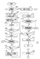
まず、シート状部材10を上動させる際の動作を、図8のフローチャートをも参照しながら詳述する。
【0076】
利用者は、現時点で開口部2を遮蔽している遮蔽機能領域から、1遮蔽機能領域だけ下にある遮蔽機能領域を開口部2を遮蔽する位置に移動させたい場合には、電源投入スイッチ93をオン操作した後、操作部94に対して、1遮蔽機能領域だけの上動の指示操作を行う。このとき、制御部95は、図8に示す一連の処理を開始する。
【0077】
なお、第1の実施形態の開口部装置1の場合、遮蔽機能領域を変更することは1日に数回程度であるので、利用者は、遮蔽機能領域を変更しない期間では電源投入スイッチ93をオフにしておくことが多いであろう。遮蔽機能領域を変更したい場合において、電源投入スイッチ93が既にオンであれば、利用者は、操作部94に対して、1遮蔽機能領域だけの上動の指示操作を直ちに行う。
【0078】
図8に示す一連の処理を開始した制御部95は、まず最初に、シート上下端センサの出力信号や、内部記憶している現時点で開口部2を遮蔽している遮蔽機能領域のシート状部材10での位置情報に基づいて、指示された1遮蔽機能領域だけの上動を実行できるか否かを判断する(ステップ100)。すなわち、現時点で開口部2を遮蔽している遮蔽機能領域が、シート状部材10の最も下の遮蔽機能領域であるか否かを判断する。
【0079】
最も下の遮蔽機能領域であると、指示された1遮蔽機能領域分の上動を実行できないので、制御部95は、異常報知部98によって操作無視の報知を実行させ(ステップ101)、図8に示す一連の処理を終了させる。
【0080】
現時点で開口部2を遮蔽している遮蔽機能領域がシート状部材10の最も下の遮蔽機能領域でない場合には、制御部95は、上側モータ18及び下側モータ26内のブレーキをアンロック状態に切り換え、上側ブレーキ22を制動力が働かない状態にすると共に、下側ブレーキ30を制動力が弱い状態に設定する(ステップ102)。
【0081】
そして、制御部95は、始動時点からの経過時間を計時する内蔵する始動時点経過タイマを起動した後、上側モータ18を始動させ、始動時点経過タイマの計時時間に基づいた加速制御を行う(ステップ103、104)。
【0082】
その後、制御部95は、始動時点経過タイマの計時時間が、加速制御から定速走行に切り換えるタイミングを規定する第1の所定時間を越えたか否かを判断する(ステップ105)。第1の所定時間を越えていなければ、制御部95は、上述したステップ104に戻って加速制御を継続する。
【0083】
例えば、上動時の定速走行での速度をXとすると、始動時点で上側モータ18に速度Xを実行させる駆動信号(電圧)を与えた場合には、速度0から速度Xへ急激に速度が変化し、そのため、シート状部材10のテンションが非常に大きくなり、シート状部材10を損傷させる恐れがある。
【0084】
そのため、加速制御を導入している。加速制御は、例えば、始動直後は、速度X/N(Nは2以上の整数)を実行させる駆動信号を一定時間Tだけ与え、次の時間Tの間は速度2X/Nを実行させる駆動信号を与え、以下、同様にして、3X/N、4X/N、…を実行させる駆動信号を一定時間Tずつ与え、最終的に速度Xにもっていく。上記時間Tで定まる、速度Xを実行させる駆動信号に切り換えるタイミングの時間が、上述した第1の所定時間である。
【0085】
加速終了タイミングになると、制御部95は、定速走行(定速上動)に切り換える(ステップ106)。定速走行中においては、制御部95は、始動時点経過タイマの計時時間が、1遮蔽機能領域分の上動に要する通常時間(始動から停止までの時間)より長い第2の所定時間を越えたか否かを確認する(ステップ107)。
【0086】
ここで、肯定結果を得られることは、1遮蔽機能領域分の上動に要する通常時間より長い第2の所定時間を越えても減速マークが検出されないので、異常が生じたことを意味し、そのため、制御部95は、上側モータ18を停止させたり異常報知部98を起動させるなどの異常発生時の処理を行い(ステップ108)、図8に示す一連の処理を終了する。
【0087】
モータ始動時点から第2の所定時間を越えていない場合には、制御部95は、減速マークが検出されたか否かを確認し(ステップ109)、検出されていないならば、ステップ106に戻って定速上動を継続させる。
【0088】
減速マークが検出されると、制御部95は、下側ブレーキ30を制動力が強い状態に切り換え、また、減速マークの検出時点からの経過時間を計時する内蔵する減速マーク検出時点経過タイマを起動する(ステップ110)。
【0089】
そして、上側モータ18に対して減速制御を行う(ステップ111)。この減速中にも、制御部95は、始動時点経過タイマの計時時間が、1遮蔽機能領域分の上動に要する通常時間より長い第2の所定時間を越えたか否か(異常が発生したか否か)を確認し(ステップ112)、越えたならば、上側モータ18を停止させたり異常報知部98を起動させたりするなどの異常発生時の処理を行い(ステップ108)、図8に示す一連の処理を終了する。
【0090】
また、減速中には、制御部95は、減速マーク検出時点経過タイマの計時時間が、減速マークの検出から通常の減速動作で停止マークが検出されるまでに要する時間より長い第3の所定時間を越えたか否か(異常が発生したか否か)を確認し(ステップ113)、越えたならば、上側モータ18を停止させたり異常報知部98を起動させたりするなどの異常発生時の処理を行い(ステップ108)、図8に示す一連の処理を終了する。
【0091】
減速期間で異常が検出されていない状態では、制御部95は、停止マークが検出されたか否かを確認しており(ステップ114)、停止マークが検出されていなければ、ステップ111に戻って、上側モータ18に対する減速制御を継続する。
【0092】
ここで、上側モータ18に対する減速制御は、下側ブレーキ30の制動力を既に強めているので、その速度の段階数を加速時よりかなり少なくしても良い。また、下側ブレーキ30の強い制動力だけで減速、停止を問題なく実行できるのならば、ステップ111での減速制御を省略するようにしても良い。
【0093】
停止マークが検出されると、制御部95は、上側モータ18の回転を停止させ、上側モータ18及び下側モータ26の内部ブレーキを共にロック状態にし、上側ブレーキ22及び下側ブレーキ30を共に制動力が働かない状態にし(ステップ115)、図8に示す一連の処理を終了する。
【0094】
図8は、1遮蔽機能領域分の上動時の動作を示すものであったが、1遮蔽機能領域分の下動時も同様な処理がなされる。すなわち、図8における「上側モータ18」を「下側モータ26」に、「下側モータ26」を「上側モータ18」に、「上側ブレーキ22」を「下側ブレーキ30」に、「下側ブレーキ30」を「上側ブレーキ22」に読み替えれば良い。
【0095】
ここで、上動は重力方向の逆方向に行われるのに対して、下動は重力方向に沿って行われるので、この第1の実施形態では、上動時の動作と下動時の動作で多少異なるようにしている。
【0096】
すなわち、下動時では、上側ガイドローラ13からシート状部材10が重力によって引き出される恐れもあるので、上動時に動作する下側ブレーキ30に比べ、上側ブレーキ22の弱い制動力や強い制動力を共に、大きくしている。例えば、相対的に表現して、上動時に動作する下側ブレーキ30の弱い制動力及び強い制動力が0.1及び2であれば、下動時に動作する上側ブレーキ22の弱い制動力及び強い制動力を3.5及び9にする。
【0097】
また、重力の影響を考慮し、下動時に始動から定速走行に切り換える時間を、上述した上動時に始動から定速走行に切り換える時間より短くしても良い。定速走行での速度自体も、上動時から変化させるようにしても良い。
【0098】
(A−3)第1の実施形態の効果
以上のように、第1の実施形態の開口部装置1によれば、遮蔽機能が異なる複数の遮蔽機能領域を長手方向に配設したシート状部材10を、上下の巻取軸11及び12の一方を駆動し、所望する遮蔽機能領域が開口部2を遮蔽する位置に停止できるようにしたので、多くの遮蔽機能を提供できる装置を実現することができる。
【0099】
また、第1の実施形態の可撓性部材運動装置(シート状部材運動装置)によれば、上動時に駆動軸となる上側巻取軸11が上側モータ18から駆動力を取り込む端部側と、下動時に駆動軸となる下側巻取軸12が下側モータ26から駆動力を取り込む端部側とを同一サイドとしたので、上動時及び下動時に斜行や蛇行をすることを防止することができる。
【0100】
さらに、第1の実施形態の可撓性部材運動装置(シート状部材運動装置)によれば、上側巻取軸11及び下側巻取軸12が上側モータ18及び下側モータ26から駆動力を取り込む端部と反対側の端部側に、制動力を多段に切り替えられる上側ブレーキ22及び下側ブレーキ30を設け、上側モータ18が駆動力を提供しているときには下側ブレーキ30が制動力を働かせ、下側モータ26が駆動力を提供しているときには上側ブレーキ22が制動力を働かせるようにしたので、シート状部材10の走行時のテンションを妥当なものとでき、シート状部材10が波打ったりすることなどを防止することができる。
【0101】
(B)第2の実施形態
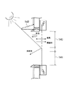
次に、本発明による開口部装置及び可撓性状部材運動装置の第2の実施形態を、図面を参照しながら簡単に説明する。
【0102】
図9は、第2の実施形態の開口部装置の電気的構成を示すブロック図であり、第1の実施形態の電気的構成を示す上述した図8との同一、対応部分には同一符号を付して示している。
【0103】
第2の実施形態の開口部装置1Aは、電源供給構成が、第1の実施形態の開口部装置1とは異なっており、図1〜図6に示した機構的な構成は第1の実施形態と同様であり、また、電源供給構成以外の電気的構成も第1の実施形態と同様である。
【0104】
すなわち、第2の実施形態の開口部装置1Aは、自然エネルギー/電気エネルギー変換部120を備え、自然エネルギー/電気エネルギー変換部120からの電気エネルギーを電源安定化回路121を介して、各部に供給するものである。
【0105】
自然エネルギー/電気エネルギー変換部120としては、太陽電池や、風力発電機や、水力発電機などを挙げることができる。自然エネルギー/電気エネルギー変換部120が太陽電池であれば、例えば、サッシ3の近傍の屋外や屋根、又は、独立した屋外に設ける。自然エネルギー/電気エネルギー変換部120が風力発電機であれば、例えば、サッシ3の近傍の屋外や屋根、又は、独立した屋外に設ける。自然エネルギー/電気エネルギー変換部120が水力発電機であれば、例えば、サッシ3の近傍の屋外や屋根に、雨水の流路機構と共に設けたり、又は、独立した屋外に設けたりする。
【0106】
電源安定化回路121は、内部に蓄電機能を備えて、自然エネルギー/電気エネルギー変換部120からの電気エネルギーの多少を調整して、安定的に電源を各部に供給するものである。
【0107】
この第2の実施形態の開口部装置1Aによれば、第1の実施形態と同様な効果を奏する。これに加え、第2の実施形態の開口部装置1Aによれば、社会の省エネルギー要求に技術的に応えることができる。
【0108】
なお、自然エネルギー/電気エネルギー変換部120からの電気エネルギーだけでは常時安定した電源供給ができない場合には、商用電源や蓄電池などを併用するようにしても良い。この場合には、電源安定化回路121内に、自然エネルギー/電気エネルギー変換部120からの電気エネルギーの蓄電量を監視し、その量によって、供給電源を切り替える構成を設けることを要する。
【0109】
(C)第3の実施形態
次に、本発明による開口部装置及び可撓性部材運動装置の第3の実施形態を、図面を参照しながら簡単に説明する。
【0110】
図10は、第3の実施形態の開口部装置1Bの要部構成を示す概略図であり、第1の実施形態に係る既述した図面との同一、対応部分には同一、対応符号を付して示している。
【0111】
第3の実施形態の開口部装置1Bは、図10に示すように、開口部2を遮蔽するシート状部材を2重にしたものであり(図10ではそれぞれ、10−1及び10−2で示している)、各シート状部材10−1、10−2を運動させる構成も、2重に設けられている。
【0112】
すなわち、2個の上側巻取軸11−1、11−2、2個の下側巻取軸12−1、12−2、2個の上側ガイドローラ13−1、13−2、2個の下側ガイドローラ14−1、14−2、2個の上側モータ18−1、18−2(図10では省略)、2個の下側モータ26−1、26−2(図10では省略)、2個の上側ブレーキ22−1、22−2(図10では省略)、2個の下側ブレーキ30−1、30−2(図10では省略)などが設けられている。
【0113】
ここで、計4個のモータ18−1、18−2、26−1及び26−2は、全て、同一サイドに設けられており、1重目のシート状部材10−1の斜行や蛇行を防止した幅方向の安定位置と、2重目のシート状部材10−2の斜行や蛇行を防止した幅方向の安定位置とが、正しく重なるようにしている。
【0114】
なお、各シート状部材10−1、10−2のそれぞれに対する遮蔽機能領域を送る制御方法は、第1の実施形態と同様である。
【0115】
この第3の実施形態の開口部装置1Bによれば、第1の実施形態とほぼ同様な効果を奏する。ここで、第3の実施形態の開口部装置1Bの場合には、シート状部材が2重に設けられているので、2個の遮蔽機能(同一でも良い)を組み合わせて発揮させることができるという効果をも奏する。
【0116】
例えば、開口部2を遮蔽する1重目の遮蔽機能領域が網戸であり、2重目の遮蔽機能領域がレース布であれば、防虫、通風機能及び弱い遮光機能を達成することができる。シート状部材が1重の場合にレース布を適用してもほぼ同様な機能を発揮できるが、レース布の場合には虫がレース布に産卵することもあり、2重の場合にはこのようなことを防止することもできる。
【0117】
なお、2重のみならず、シート状部材を3重以上設ける要にしても良いことは勿論である。
【0118】
この第3の実施形態を変形した実施形態としては、図11に示すものを挙げることができる。
【0119】
すなわち、シート状部材10としてエンドレスのものを適用し、これを上側主軸11A及び下側主軸12Aに巡回的に掛け渡すことにより、2個の遮蔽機能領域を2重に開口部2Aの遮蔽位置に位置させるものであっても良い。
【0120】
この図11の装置では、一方の主軸(例えば11A)だけを駆動軸にすることもでき、また、シート状部材10の走行方向によって、駆動力となる主軸を、主軸11A及び11Bで切り替えることもできる。後者の場合には、第1の実施形態について説明した理由により、主軸11Aでの駆動力が付与される端部と、主軸11Bでの駆動力が付与される端部とを、シート状部材10の幅方向から見て同一サイドとする。
【0121】
(D)他の実施形態
上記各実施形態の説明においても、種々の変形実施形態に言及したが、更に、以下に例示するような変形実施形態を挙げることができる。
【0122】
(D−1) 上記各実施形態においては、開口部のほぼ全面をシート状部材が遮蔽するものを示したが、遮蔽面積はこれに限定されるものではない。
【0123】
例えば、図12に示すように、サッシ(装置)130が、サッシ上枠131、サッシ中間桟132及びサッシ下枠133を有し、上下2段にサッシガラス(図示せず)を装着する構成の場合に、上下のサッシガラス部の一方のみ(図12では上側)を、本発明の開口部装置134で遮蔽するようにしても良い。
【0124】
以上のように、開口部が明確に2分割又はそれ以上分割されていなくても、その一部を遮蔽するようにしても良い。
【0125】
なお、開口部の一部を遮蔽する場合であっても、「特許請求の範囲」では遮蔽対象を「開口部」と呼んでいる。
【0126】
(D−2) 上記各実施形態においては、シート状部材の移動を遮蔽機能領域を単位として行い、開口部を遮蔽する位置にはいずれかの遮蔽機能領域だけが位置するものを示したが、複数の遮蔽機能領域の部分(又は複数の遮蔽機能領域)が上下に並んで遮蔽するようなものであっても良い。
【0127】
例えば、図13に示すように、開口部の上半分を網(遮蔽機能領域)140の下半分で遮蔽すると共に、開口部の下半分を遮光シート(遮蔽機能領域)141の上半分で遮蔽するようなことを可能としても良い。例えば、屋外に庇142がある場合において、遮光機能と、防虫・通風・換気機能とを同時に発揮させる場合において、図13の遮蔽状態は有効である。この場合には、シート状部材に、遮蔽機能領域の長手方向の半分の単位での位置管理を行うことができるマークを付与し、遮蔽機能領域の半分の単位での上動や下動を可能とする。
【0128】
また、図13に示すような遮蔽機能領域の半分ではなく、2遮蔽機能領域の任意の部分量の組合せで、開口部を遮蔽できるようにしても良い。例えば、操作部に、操作している期間だけ上動又は下動させる任意上動キーや任意下動キーを設け、任意上動キーや任意下動キーが操作されている期間だけシート状部材を移動させ、操作が終わったときのシート状部材の領域で開口部を遮蔽するようにしても良い。
【0129】
さらに、1遮蔽機能領域として(遮蔽機能領域自体として)、図13に示すような上下部分で遮蔽機能が異なる領域を、シート状部材に設けるようにしても良い。
【0130】
(D−3) 開口部装置としてのシート状部材における遮蔽機能領域の機能は任意である。例えば、防火、防水、防風、防犯、防弾、遮光、遮音、断熱、日除け、雨除け、目隠し、太陽光の拡散光の取り入れ、背景画像(掲示板的なものを含む)の提供、記載及び消去可能な黒板的機能、プロジェクタやスライド用のスクリーンを挙げることができる。
【0131】
シート状部材における各遮蔽機能領域の材料も任意である。例えば、布(遮光タイプ、シリカクロスを用いた防火、防水タイプなど)、網(防虫用、日除け用など)、紙(障子紙など)、鋼製ネット(目隠し用、防弾用、日除け用など)、鋼板(防犯用、防火用など)、パイプ(パイプを並設してシート状的(すだれ的)にしたもの;防犯用、防火用など)を挙げることができる。また、スラットシャッターでのスラット的なものであっても良い。
【0132】
また、シート状部材の構成も、図6に示したものに限定されず、遮蔽機能領域が並設されているものであれば良い。例えば、図14に示すように、一対のワイヤ150及び151に、梯子状に複数の紐152を結び、相前後する紐152に遮蔽機能を発揮する複数の遮蔽機能単位シート153(図14は、「網」、「目隠し」、「透明シート」の例)を取り付けたものであっても良い。なお、図14の例では、図示されている中の最も下の遮蔽領域はスラットでできており、スラットは直接一対のワイヤ150及び151に取り付けられている。
【0133】
なお、鋼製ネット、鋼板、パイプなどが材料である場合でも、全体として見て、可撓性を有することが必要である。そのため、特許請求の範囲では、「可撓性部材」という表現を適用している。
【0134】
さらに、シート基材に対する各遮蔽機能領域の取付は、接着、溶着、縫着、差込などのいずれであっても良い。また、各遮蔽機能領域毎のシート部分を用意しておき、それらを直接結合して、シート状部材を完成させても良い。
【0135】
(D−4) 上記各実施形態においては、シート状部材(従って開口部装置)を屋内側に設けたものを示したが、本発明は、これに限定されるものではない。例えば、シート状部材を屋外側に設けるようにしても良い。また例えば、サッシ装置が2重サッシ構成のものであれば、2重サッシの間に遮蔽機能を発揮するシート状部材の部分を通すようにしても良く、複層ガラスを有するものであれば、複層ガラスの間に遮蔽機能を発揮するシート状部材の部分を通すようにしても良い。
【0136】
(D−5) 上記各実施形態においては、開口部を遮蔽する位置にあるシート状部材が何ら保護されていないものを示したが、透明ガラスなどの蓋体でカバーされているものであっても良い。すなわち、開口部を遮蔽する位置にあるシート状部材もケースに入っているものであっても良い。
【0137】
ここで、蓋体が、一方の端部に設けられた軸を中心に回動するものや、スライドするものであれば、蓋体が開き始める蓋体の端部を駆動モータを位置させるサイドにすることが好ましい。上述したように、シート状部材は、モータが設けられたサイドに、スライドしようとする力が僅かに働くため、ブレーキに比べてモータの保守点検がより重要となるためである。
【0138】
(D−6) 上記各実施形態においては、1枚のシート状部材を駆動するために、上下それぞれにモータを設けたものを示したが、1個のモータを設け、クラッチや運動伝達機構などによって、そのモータの駆動力を、上側巻取軸又は下側巻取軸の一方に伝達するようにしても良い。なお、特許請求の範囲における「第1の駆動源」及び「第2の駆動源」は、この場合を含むものとする。
【0139】
この場合であっても、上側巻取軸及び下側巻取軸における駆動力が伝達される端部は、同一サイドであることが好ましい。
【0140】
同様に、1個のブレーキを、上側巻取軸及び下側巻取軸に対して択一的に機能させるようにしても良い。なお、特許請求の範囲における「第1の制動機構」及び「第2の制動機構」は、この場合を含むものとする。
【0141】
(D−7) 上記各実施形態では、シート状部材に対して、全く同一の遮蔽機能を発揮する遮蔽機能領域を設けないものを示したが、全く同一の遮蔽機能を発揮する遮蔽機能領域を複数設けるようにしても良い。
【0142】
例えば、シート状部材の遮蔽機能領域数が多い場合には、頻繁に選択されると思われる遮蔽機能領域を複数設け、その遮蔽機能領域への移動時間を短縮できるようにしても良い。
【0143】
(D−8) 上記各実施形態では、シート状部材が一旦完成された後は、遮蔽機能領域の部分的な変更などをできないものを示したが、遮蔽機能領域の機能追加や削除に伴う部分的な変更、あるいは破損、損傷などに伴う部分的な交換に対応できるようにしても良い。上述した図6を例に説明すると、遮蔽機能領域としての遮光シート70−1、障子紙70−2、網70−3などを、シート状部材10の本体に対し、ファスナーなどの着脱部材によって着脱自在に取り付けることにより、シート状部材10の遮蔽機能領域の部分的な変更や部分的な交換を可能とするようにしても良い。上述した図14に関しても同様である。
【0144】
(D−9) 上記各実施形態においては、上側モータ及び下側モータが、ブレーキ機構(ロック機構)を内蔵しているものであったが、ブレーキ機構(ロック機構)がないモータを適用するようにしても良い。
【0145】
すなわち、上側巻取軸及び下側巻取軸にはそれぞれ、ブレーキが連結されているので、これらブレーキの制動力を利用して、シート状部材を停止させている期間での上側巻取軸及び下側巻取軸の不要な回転を防止するようにしても良い。
【0146】
(D−10) 上記各実施形態においては、上動動作期間内で下側のブレーキの制動力だけを変化させ、下動動作期間内で上側のブレーキの制動力だけを変化させるものを示したが、上動動作期間内でも下動動作期間内でも、上側及び下側のブレーキの制動力を変化させるようにしても良い。
【0147】
上動を例に説明する。例えば、上動の初期の加速時の速度の変化を、上側モータには、安定時の定速走行での速度を達成させる駆動信号を与え、この期間で、上側ブレーキに与える制動力の制御信号を徐々に弱めることで、初期の所望する加速時変化を得るようにしても良い。また例えば、上動における停止前の減速時にも、下側ブレーキだけでなく、上側ブレーキの制動力を働かせ、所望する減速時変化を得るようにしても良い。なお、この場合、シート状部材のテンションが緩くなり過ぎることを防止するように、下側ブレーキの制動力の方を大きくしていることが好ましい。
【0148】
また、シート状部材のテンション調整を意図した上側ブレーキ及び下側ブレーキは、対応する上側巻取軸及び下側巻取軸に制動力を与えるものであったが、他の位置や部材に制動力を付与し、シート状部材の走行時のテンションを調整するものであっても良い。例えば、第1の実施形態の上側及び下側のガイドローラをそれぞれ、シート状部材を挟むように設けられた2個のガイドローラの組に代え、ここに(例えば、一方のローラに)、ブレーキの制動力を作用させるようにしても良い。
【0149】
(D−11) 上記各実施形態においては、上下にガイドローラを設けたものを示したが、これらガイドローラを省略するものであっても良い。
【0150】
逆に、上下のガイドローラ間に、さらに、1以上のガイドローラを有するものであっても良い。この場合においては、上下のガイドローラ間のシート状部材の部分は、同一平面上に存在しなくても良い。
【0151】
(D−12) 上記各実施形態においては、シート状部材の移動を指示する操作部が制御部に有線で接続されているものを示したが、リモコンシステムを適用するようにしても良い。
【0152】
(D−13) 上記各実施形態においては、操作部に対する操作がなされたときに、シート状部材を所定量だけ移動させるものを示したが、自動移動機能を導入するようにしても良い。
【0153】
例えば、異なる背景画像を提供する遮蔽機能領域がシート状部材に連続的に複数配設されている場合において、各遮蔽機能領域を所定時間(例えば30分)だけ停止させると、次の位置の遮蔽機能領域に自動的に移動させるようにしても良い。
【0154】
(D−14) 上記各実施形態においては、光電センサからの出力によって、遮蔽機能領域の位置管理を行うものを示したが、他の方法によっても良いことは勿論である。例えば、モータとしてステッピングモータを適用しているのであれば、その駆動のためのパルス数によって遮蔽機能領域の位置管理を行っても良い。また、上側及び又は下側巻取軸にロターリーエンコーダを設け、その出力によって、遮蔽機能領域の位置管理を行っても良い。また、リミットスイッチなどの機構的な位置検出構成によってシート状部材の位置を検出して(この場合、シート状部材の幅方向の端部に貫通孔や突片が必要となる)、遮蔽機能領域の位置管理を行っても良い。
【0155】
(D−15) 上記各実施形態においては、シート状部材の走行時の異常を、始動からの時間などによって監視するものを示したが、これに換え、又は、これに加えて、他の方法を適用するようにしても良い。例えば、開口部を遮蔽する位置のシート状部材の部分のテンションを検出するテンションセンサ(例えば、テンションローラ)を設け、テンションによって異常発生を監視するようにしても良い。
【0156】
(D−16) 上記各実施形態においては、シート状部材の走行方向が上下のものを示したが、左右方向や水平方向(地面に平行)であっても良く、さらには、斜め方向(例えば天窓に適用)であっても良い。
【0157】
また、湾曲面に沿って走行するものであっても良い。例えば、外壁が湾曲し、窓も湾曲している建物が最近多く出現してきており、そのような湾曲している窓の湾曲面に沿って、シート状部材を走行させるものであっても良い。この場合には、適宜な位置に、ガイドローラが必要となる。
【0158】
(D−17) 上記各実施形態においては、窓的な開口部を対象とした開口部装置を示したが、開口部の種類はこれに限定されず、屋根やドア的なものであっても良い。
【0159】
例えば、テラスやカーポートやアーケードの屋根などであっても良い。これらの屋根の場合、物体を通過させる開口部ではないが、物体を通過し得る開口部を設けて、本発明の開口部装置を設けても良く、また、屋根の内側又は外側に本発明の開口部装置を設けても良い。後者の場合、屋根自体は、物体を通過し得る開口部ではないが、光学的な開口部になっており、本発明の対象の開口部はこのような開口部を含むものとする。
【0160】
また、本発明が対象とする開口部は、建造構築物についての開口部に限定されず、例えば、船舶や車両などの開口部であっても良い。
【0161】
(D−18) 本発明の可撓性部材運動装置は、開口部装置に適用することを意図してなされたものであるが、可撓性部材の往復動を要する、固定的な又は可搬可能な他の装置に適用することができるものである。
【0162】
開口部装置以外の他の装置に、本発明の可撓性部材運動装置を適用した場合においても、開口部装置に適用した場合と同様な上記各実施形態(変形実施形態を含む)の特徴をそのまま適用可能である。例えば、電源として太陽電池を利用することもできる。
【0163】
【発明の効果】
本発明の開口部装置によれば、1装置でありながら、多くの遮蔽機能を提供することができる。
【0164】
また、本発明の可撓性部材運動装置によれば、可撓性部材を、蛇行や斜行や波打ちなく、走行させることができる。
【図面の簡単な説明】
【図1】第1の実施形態の開口部装置の縦断面図(図2におけるI−I線方向の縦断面図)である。
【図2】第1の実施形態の開口部装置の一部構成を取り出して示す概略斜視図である。
【図3】図1における上側のブラケット部の正面図である。
【図4】図1におけるIV−IV線断面図である。
【図5】図1におけるV−V線断面図である。
【図6】第1の実施形態でのシート状部材(可撓性部材)の構成を示す平面図である。
【図7】第1の実施形態の開口部装置の電気的構成を示すブロック図である。
【図8】第1の実施形態の開口部装置の動作を示すフローチャートである。
【図9】第2の実施形態の開口部装置の電気的構成を示すブロック図である。
【図10】第3の実施形態の開口部装置の要部構成を示す概略図である。
【図11】第3の実施形態の開口部装置を変形した構成例を示す概略図である。
【図12】本発明の開口部装置の遮蔽対象となる開口部の他の例を示す概略図である。
【図13】シート状部材の複数の遮蔽機能領域を開口部の遮蔽位置に同時に位置させることが可能な他の実施形態の説明図である。
【図14】他の実施形態によるシート状部材の構成例を示す説明図である。
【符号の説明】
1、1A、1B…開口部装置、2…開口部、10…シート状部材、11…上側巻取軸、12…下側巻取軸、22…上側ブレーキ、30…下側ブレーキ、70−1〜70−4…シート状部材における遮蔽機能領域。[0001]
BACKGROUND OF THE INVENTION
The present invention relates to an opening device for shielding an opening, and a flexible member exercise device capable of traveling and stopping a flexible member in both directions.
[0002]
[Prior art]
For example, an opening device for shielding an opening of a building, a vehicle, a ship, or the like has few types of shielding functions that it takes charge of (approximately one).
[0003]
For example, the window also has a ventilation function when opened, but has a function of taking outside light indoors when the window is closed. In addition, the blind has a function of controlling the amount of outside light to be taken indoors. Furthermore, the screen door has a ventilation function while preventing insects from entering the room.
[0004]
[Problems to be solved by the invention]
However, since the conventional opening device has a small number of functions in charge as described above, when a large number of functions are required, a plurality of opening devices having different functions are arranged in parallel in the opening. Must. For example, as described above, a blind and a screen door are also provided on the side of the window.
[0005]
The present invention has been made in consideration of the above points, and an object of the present invention is to provide an opening device capable of realizing many shielding functions related to the opening with one device.
[0006]
Another object of the present invention is to provide a flexible member motion device suitable for application to such an opening device.
[0007]
[Means for Solving the Problems]
In order to solve such a problem, the opening device according to the first aspect of the present invention includes (1) a plurality of types of shielding function regions having different shielding functions when positioned at a position where the opening is shielded in the reciprocating direction. (2) a first main shaft serving as a drive shaft when the shield function member is moved forward, and (3) a drive when the shield function member is moved backward. A second spindle serving as an axis; (4) a first drive source that receives power supply and applies a driving force to the first spindle; and (5) receives power supply and supplies the second spindle to the second spindle. A second driving source for providing a driving force; (6) A braking force is applied to the second main shaft or a portion of the shielding function member at a position near the second main shaft so as to prevent the shielding function member from moving forward during at least a part of the period when the first main shaft is driven. A first braking mechanism capable of electrically controlling a braking force, and (7) preventing the backward movement of the shielding function member during at least a part of the period during which the second main shaft is driven. A second braking mechanism capable of electrically controlling a braking force, which applies a braking force to the first main shaft or a portion of the shielding function member located in the vicinity thereof; (8) The first and / or second drive source when the shielding function member needs to be moved forward, moved backward, or stopped , And the first and second braking mechanisms Control means for controlling the operation of (9) The first and second braking mechanisms can take at least a state where there is no braking force, a state where the braking force is weak, and a state where the braking force is strong. (10) 11-1) When moving the shielding function member forward, at the start of the forward movement, the first braking mechanism is set to a state where there is no braking force, and the second braking mechanism is set to a state where the braking force is weak. The first drive source is started, acceleration control is performed based on the time measured by the elapsed timer, and constant speed travel is performed when the time measured by the elapsed timer reaches a predetermined time that defines the timing for switching from acceleration control to constant speed travel. When the shielding function member reaches the deceleration start position, the second braking mechanism is switched to a strong braking force, the deceleration control for the first drive source is performed, and the shielding function member is stopped. To reach And stopping the first drive source and setting the second braking mechanism to a state where there is no braking force. (11-2) When returning the shielding function member, The braking mechanism is set to a state where there is no braking force, the first braking mechanism is set to a state where the braking force is weak, the second drive source is started, and acceleration control based on the time measured by the elapsed timer is performed. When the elapsed timer time reaches a predetermined time that defines the timing for switching from acceleration control to constant speed travel, the speed is switched to constant speed travel. When the shielding function member reaches the deceleration start position, the first braking mechanism is controlled. The power is switched to a strong state, the deceleration control for the second drive source is performed, and when the shielding function member reaches the stop position, the second drive source is stopped and the first braking mechanism is applied to the braking force. Gana To state It is characterized by that.
[0009]
Second The flexible member exercise apparatus according to the present invention includes (1) a flexible member in which at least a part capable of reciprocating is a sheet, and (2) driving when the flexible member is moved forward. A first main shaft serving as an axis; (3) a second main shaft serving as a drive shaft when the flexible member is moved backward; and (4) a driving force applied to the first main shaft upon receiving power supply. (5) a second driving source that receives power supply and applies a driving force to the second main shaft; and (6) at least one of the first main shaft being driven. The braking force can be controlled electrically by applying a braking force to the portion of the flexible member at or near the second main shaft so as to prevent the flexible member from moving forward during the period of the portion. A first braking mechanism, and (7) preventing the return of the flexible member during at least a part of the period when the second main shaft is driven. A second braking mechanism capable of electrically controlling a braking force, which applies a braking force to the first main shaft or a portion of the flexible member at a position near the first main shaft; and (8) the flexibility Control the operation of the first and / or second drive source and the first and / or second braking mechanism when it is necessary to move the member forward, return, or stop. Control means for (9) The first and second braking mechanisms can be at least in a state where there is no braking force, a state where the braking force is weak, and a state where the braking force is strong. (10) The control means includes (11 -1) When the flexible member is moved forward, at the start of the forward movement, the first braking mechanism is set to have no braking force, and the second braking mechanism is set to have a weak braking force. The first drive source is started, acceleration control is performed based on the time measured by the elapsed timer, and constant speed travel is performed when the time measured by the elapsed timer reaches a predetermined time that defines the timing for switching from acceleration control to constant speed travel. When the flexible member reaches the deceleration start position, the second braking mechanism is switched to a state where the braking force is strong, and the deceleration control for the first drive source is performed so that the flexible member When reaching the stop position, The first drive source is stopped and the second braking mechanism is set to have no braking force. (11-2) When the flexible member is moved backward, the second braking is performed at the start of the backward movement. The mechanism is set to a state where there is no braking force, the first braking mechanism is set to a state where the braking force is weak, the second drive source is started, and acceleration control based on the time measured by an elapsed timer is performed, When the time measured by the elapsed timer reaches a predetermined time that defines the timing for switching from acceleration control to constant speed travel, the time is switched to constant speed travel. When the flexible member reaches the deceleration start position, the first braking mechanism is braked. Is switched to a strong state, deceleration control is performed on the second drive source, and when the flexible member reaches the stop position, the second drive source is stopped and the first braking mechanism is applied to the braking force. No state It is characterized by that.
[0010]
DETAILED DESCRIPTION OF THE INVENTION
(A) First embodiment
(A-1) Configuration of the first embodiment
Hereinafter, a first embodiment of an opening device and a flexible member exercise device according to the present invention will be described in detail with reference to the drawings. In addition, the opening part apparatus of this 1st Embodiment is comprised including the flexible member exercise | movement apparatus.
[0011]
FIG. 2 is a schematic perspective view showing the main configuration of the
[0012]
As shown in FIGS. 1, 4 and 5, the
[0013]
As shown in FIG. 2, the
[0014]
As will be described later, the sheet-
[0015]
The upper winding
[0016]
On one end of the upper winding shaft 11 (for example, the right end when viewed from the indoor side), a motion transmission mechanism including a pair of
[0017]
On the other hand, the other end portion of the upper winding shaft 11 (for example, the left end portion when viewed from the indoor side) side is a motion transmission mechanism including a pair of
[0018]
Similarly, a motor (lower motor) 26 is provided on one end (for example, the right end as viewed from the indoor side) side of the lower winding
[0019]
Further, the other end (for example, the left end as viewed from the indoor side) of the lower winding
[0020]
Each of the upper winding
[0021]
In addition, a width direction position restricting disk may be provided on the other end side of the upper winding
[0022]
The upper winding
[0023]
However, in the first embodiment, as described above, the
[0024]
The length in the vertical direction of the
[0025]
When the inventor of the present application rotates the winding shaft (11 or 12) while repeating trial manufacture and durability experiment, the end side where the driving force is introduced (the end where the motor is provided). It was discovered that the position of the sheet-
[0026]
In consideration of the property that the position in the width direction of the sheet-
[0027]
On the other hand, when the upper and
[0028]
Each of the
[0029]
By this tension control function, it is possible to prevent the sheet-
[0030]
The
[0031]
At each of the positions higher and lower than the
[0032]
[0033]
Upper components such as the upper winding
[0034]
Similarly, lower components such as the lower winding
[0035]
A
[0036]
[0037]
The reason why the brush-
[0038]
Although the guide rails 60 and 61 are provided with the
[0039]
Incidentally, when there is no function of preventing meandering or skewing as described above, or a function of preventing waviness during traveling, the left and right ends of the sheet-
[0040]
Further, these
[0041]
FIG. 6 is a plan view showing a state in which the sheet-
[0042]
As shown in FIG. 6, the sheet-
[0043]
Each of the shielding function regions 70-1,..., 70-4 has a different function when it is located at a position where it shields the
[0044]
As an example of the sheet-
[0045]
When the
[0046]
The shielding function of the shielding function area 70-i is not limited to the above. For example, a plurality of light shielding amounts may be provided, or may have a shielding function such as sound insulation, heat insulation, blindfolding, and provide an artistic background such as a picture pattern or a character pattern It may be. Modifications from this viewpoint will be described in more detail.
[0047]
A plurality of marks 73 </ b> R and 73 </ b> L used for position management of the shielding function area and the like are attached to the right end and the left end of the sheet-like member 10 (only one end may be used). The
[0048]
The
[0049]
Two
[0050]
In the case of the mark example shown in FIG. 6, the detection marks 73L-1 and 73L-2 for the upper end position are also used as the deceleration mark and the stop mark in the uppermost shielding function area 70-1 during the downward movement. The lower end position detection marks 73L-1 and 73L-2 are also a deceleration mark and a stop mark of the lowermost shielding function area 70-4 during upward movement.
[0051]
Although not shown in FIGS. 2 to 5, a photoelectric sensor (mark detection sensor) including a light emitting unit and a light receiving unit for detecting the
[0052]
The position of the area position sensor and the sheet upper / lower end sensor may be any location as long as the
[0053]
In addition, although a reflective type can be applied as the photoelectric sensor (in this case also constitutes another embodiment of the present invention), the sheet-
[0054]
The distance between the light emitting unit and the light receiving unit constituting the photoelectric sensor is about 5 to 10 cm. For example, it is preferable to apply a light emitting unit and a light receiving unit that can handle a distance of about 3 m. This is in consideration of the case where the end of the sheet-
[0055]
FIG. 7 is a block diagram showing an electrical configuration of the
[0056]
The
[0057]
A
[0058]
The
[0059]
The power-on
[0060]
The
[0061]
Here, when the number of shielding function areas in the sheet-
[0062]
When the number of shielding function areas in the sheet-
[0063]
Furthermore, the number of the shielding functional areas to be moved up or down may be inputted numerically. In this case, in the
[0064]
The
[0065]
The
[0066]
The
[0067]
In the case of the first embodiment, as the
[0068]
The
[0069]
As described above, the
[0070]
The level of braking force that can be taken by the
[0071]
The
[0072]
Configurations other than the
[0073]
For example, all may be provided in the
[0074]
(A-2) Operation of the first embodiment
Next, operation | movement of the
[0075]
First, the operation when the sheet-
[0076]
When the user wants to move the shielding function area which is lower by one shielding function area from the shielding function area currently shielding the
[0077]
In the case of the
[0078]
The
[0079]
If it is the lowest shielding function area, it is not possible to execute the upward movement for the designated one shielding function area, so the
[0080]
When the shielding function area shielding the
[0081]
Then, the
[0082]
Thereafter, the
[0083]
For example, assuming that the speed at constant speed during upward movement is X, when a drive signal (voltage) for executing the speed X is given to the
[0084]
Therefore, acceleration control is introduced. In the acceleration control, for example, immediately after starting, a drive signal for executing the speed X / N (N is an integer of 2 or more) is given for a certain time T, and during the next time T, the drive signal for executing the speed 2X / N. In the same manner, a drive signal for executing 3X / N, 4X / N,... Is given by a predetermined time T, and finally the speed X is reached. The time of switching to the drive signal for executing the speed X determined by the time T is the first predetermined time described above.
[0085]
When the acceleration end timing is reached, the
[0086]
Here, obtaining an affirmative result means that the deceleration mark is not detected even if the second predetermined time longer than the normal time required for the upward movement of one shielding function region is exceeded, and thus an abnormality has occurred, Therefore, the
[0087]
If the second predetermined time has not been exceeded since the start of the motor, the
[0088]
When the deceleration mark is detected, the
[0089]
Then, deceleration control is performed on the upper motor 18 (step 111). Even during this deceleration, the
[0090]
Further, during deceleration, the
[0091]
In a state where no abnormality is detected during the deceleration period, the
[0092]
Here, in the deceleration control for the
[0093]
When the stop mark is detected, the
[0094]
Although FIG. 8 shows the operation at the time of upward movement for one shielding function area, the same processing is performed at the time of downward movement for one shielding function area. That is, “
[0095]
Here, while the upward movement is performed in the direction opposite to the gravity direction, the downward movement is performed along the direction of gravity. Therefore, in the first embodiment, the upward movement and the downward movement are performed. It is a little different.
[0096]
That is, at the time of the downward movement, the sheet-
[0097]
Further, in consideration of the influence of gravity, the time for switching from starting to constant speed traveling during downward movement may be shorter than the time for switching from starting to constant speed traveling during upward movement described above. The speed itself in constant speed running may be changed from the time of upward movement.
[0098]
(A-3) Effects of the first embodiment
As described above, according to the
[0099]
In addition, according to the flexible member exercise device (sheet-like member exercise device) of the first embodiment, the upper winding
[0100]
Furthermore, according to the flexible member exercise device (sheet-like member exercise device) of the first embodiment, the upper winding
[0101]
(B) Second embodiment
Next, a second embodiment of the opening device and the flexible member motion device according to the present invention will be briefly described with reference to the drawings.
[0102]
FIG. 9 is a block diagram showing the electrical configuration of the opening device of the second embodiment. The same reference numerals are given to the corresponding parts in FIG. 8 showing the electrical configuration of the first embodiment. It is attached.
[0103]
The opening device 1A of the second embodiment is different from the
[0104]
That is, the opening device 1A of the second embodiment includes a natural energy / electric
[0105]
Examples of the natural energy / electrical
[0106]
The power
[0107]
According to the opening device 1A of the second embodiment, the same effects as those of the first embodiment can be obtained. In addition to this, according to the opening device 1A of the second embodiment, it is possible to technically meet the energy saving demands of society.
[0108]
In addition, when a stable power supply cannot always be performed with only the electric energy from the natural energy / electric
[0109]
(C) Third embodiment
Next, a third embodiment of the opening device and the flexible member exercise device according to the present invention will be briefly described with reference to the drawings.
[0110]
FIG. 10 is a schematic diagram showing the configuration of the main part of the opening device 1B of the third embodiment. The same and corresponding parts as those in the already described drawings according to the first embodiment are assigned the same and corresponding reference numerals. As shown.
[0111]
As shown in FIG. 10, the
[0112]
That is, two upper winding shafts 11-1, 11-2, two lower winding shafts 12-1, 12-2, two upper guide rollers 13-1, 13-2, two Lower guide rollers 14-1, 14-2, two upper motors 18-1, 18-2 (omitted in FIG. 10), two lower motors 26-1, 26-2 (omitted in FIG. 10) Two upper brakes 22-1, 22-2 (omitted in FIG. 10), two lower brakes 30-1, 30-2 (omitted in FIG. 10), and the like are provided.
[0113]
Here, a total of four motors 18-1, 18-2, 26-1, and 26-2 are all provided on the same side, and the skew and meander of the first sheet-like member 10-1 are provided. The stable position in the width direction in which the sheet is prevented from overlapping with the stable position in the width direction in which the skew and meandering of the second sheet-like member 10-2 are prevented.
[0114]
In addition, the control method which sends the shielding function area | region with respect to each of each sheet-like member 10-1, 10-2 is the same as that of 1st Embodiment.
[0115]
According to the opening device 1B of the third embodiment, there are substantially the same effects as those of the first embodiment. Here, in the case of the opening device 1B of the third embodiment, since the sheet-like member is provided twice, it is possible to exhibit two shielding functions (which may be the same) in combination. There is also an effect.
[0116]
For example, if the first shielding function area that shields the
[0117]
It goes without saying that not only double but also three or more sheet-like members may be provided.
[0118]
As an embodiment obtained by modifying the third embodiment, the one shown in FIG. 11 can be cited.
[0119]
That is, by applying an endless one as the sheet-
[0120]
In the apparatus of FIG. 11, only one main shaft (for example, 11A) can be used as a drive shaft, and the main shaft serving as a driving force can be switched between the
[0121]
(D) Other embodiments
In the description of each of the above embodiments, various modified embodiments have been referred to, but further modified embodiments as exemplified below can be given.
[0122]
(D-1) In each of the above embodiments, the sheet-like member shields substantially the entire surface of the opening, but the shielding area is not limited to this.
[0123]
For example, as shown in FIG. 12, a sash (device) 130 has a sash
[0124]
As described above, even if the opening is not clearly divided into two or more, a part of the opening may be shielded.
[0125]
Even when a part of the opening is shielded, the “claim” refers to the shielding object as the “opening”.
[0126]
(D-2) In each of the above embodiments, the movement of the sheet-like member is performed in units of the shielding function area, and only one of the shielding function areas is located at the position where the opening is shielded. A part (or a plurality of shielding function areas) of a plurality of shielding function areas may be shielded side by side.
[0127]
For example, as shown in FIG. 13, the upper half of the opening is shielded by the lower half of the net (shielding functional area) 140, and the lower half of the opening is shielded by the upper half of the light shielding sheet (shielding functional area) 141. It may be possible to do this. For example, when there is a
[0128]
Moreover, you may enable it to shield an opening part with the combination of the arbitrary partial amounts of 2 shielding function area | regions instead of the half of a shielding functional area | region as shown in FIG. For example, the operation unit is provided with an arbitrary upward movement key or an arbitrary downward movement key that moves up or down only during the operated period, and the sheet-like member is moved only during the period during which the arbitrary upward movement key or arbitrary downward movement key is operated. The opening may be shielded by the region of the sheet-like member when the operation is finished.
[0129]
Further, as one shielding function region (as the shielding function region itself), regions having different shielding functions in the upper and lower portions as shown in FIG. 13 may be provided in the sheet-like member.
[0130]
(D-3) The function of the shielding functional area in the sheet-like member as the opening device is arbitrary. For example, fire prevention, waterproof, windproof, crime prevention, bulletproof, shading, sound insulation, heat insulation, awning, rain protection, blindfolding, taking in diffused sunlight, providing background images (including those in a bulletin board), description and deletion Such as blackboard-like functions, projectors and slide screens.
[0131]
The material of each shielding functional region in the sheet-like member is also arbitrary. For example, cloth (light-shielding type, fireproof using silica cloth, waterproof type, etc.), net (insect-proof, sunscreen, etc.), paper (shoji paper, etc.), steel net (blindfold, bulletproof, sunshade, etc.) Steel sheets (for crime prevention, fire prevention, etc.) and pipes (those arranged in parallel to form a sheet of paper; for crime prevention, fire prevention, etc.). Further, it may be a slat type with a slat shutter.
[0132]
Also, the configuration of the sheet-like member is not limited to that shown in FIG. For example, as shown in FIG. 14, a plurality of shielding function unit sheets 153 (see FIG. 14) that tie a plurality of
[0133]
Even when a steel net, a steel plate, a pipe or the like is a material, it is necessary to have flexibility as a whole. Therefore, in the claims, the expression “flexible member” is applied.
[0134]
Furthermore, attachment of each shielding function area | region with respect to a sheet | seat base material may be any of adhesion | attachment, welding, sewing, insertion. Alternatively, a sheet portion may be prepared for each shielding function area, and these may be directly coupled to complete the sheet-like member.
[0135]
(D-4) In each said embodiment, although the sheet-like member (thus opening part apparatus) provided what was provided in the indoor side, this invention is not limited to this. For example, the sheet-like member may be provided on the outdoor side. Also, for example, if the sash device has a double sash configuration, the portion of the sheet-like member that exhibits a shielding function may be passed between the double sashes, and if it has a multilayer glass, You may make it pass the part of the sheet-like member which exhibits a shielding function between multilayer glass.
[0136]
(D-5) In each of the above embodiments, the sheet-like member at the position where the opening is shielded is not protected at all, but is covered with a cover such as transparent glass. Also good. That is, the sheet-like member at the position where the opening is shielded may also be contained in the case.
[0137]
Here, if the lid rotates around an axis provided at one end or slides, the end of the lid that starts to open is on the side where the drive motor is positioned. It is preferable to do. As described above, since the sheet-like member is slightly slidable on the side where the motor is provided, the maintenance of the motor is more important than the brake.
[0138]
(D-6) In each of the above embodiments, a motor is provided on each of the upper and lower sides to drive one sheet-like member. However, one motor is provided, and a clutch, a motion transmission mechanism, and the like are provided. Thus, the driving force of the motor may be transmitted to one of the upper winding shaft and the lower winding shaft. The “first drive source” and the “second drive source” in the claims include this case.
[0139]
Even in this case, it is preferable that the end portions to which the driving force is transmitted in the upper winding shaft and the lower winding shaft are on the same side.
[0140]
Similarly, one brake may function alternatively with respect to the upper winding shaft and the lower winding shaft. The “first braking mechanism” and the “second braking mechanism” in the claims include this case.
[0141]
(D-7) In each of the above-described embodiments, the sheet-like member is not provided with a shielding function region that exhibits the same shielding function, but a shielding function region that exhibits the same shielding function is provided. A plurality of them may be provided.
[0142]
For example, when the number of shielding function areas of the sheet-like member is large, a plurality of shielding function areas that are considered to be frequently selected may be provided so that the movement time to the shielding function area can be shortened.
[0143]
(D-8) In each of the above embodiments, after the sheet-like member is once completed, a part that cannot be partially changed in the shielding function area is shown. It may be possible to cope with a partial change due to a general change or breakage or damage. Referring to FIG. 6 as an example, the light shielding sheet 70-1, the shoji paper 70-2, the mesh 70-3, and the like as the shielding functional region are attached to and detached from the main body of the sheet-
[0144]
(D-9) In each of the above embodiments, the upper motor and the lower motor incorporate the brake mechanism (lock mechanism), but a motor without a brake mechanism (lock mechanism) is applied. Anyway.
[0145]
That is, since the brake is connected to the upper winding shaft and the lower winding shaft, respectively, the upper winding shaft and the upper winding shaft during the period in which the sheet-like member is stopped using the braking force of these brakes. You may make it prevent the unnecessary rotation of a lower winding shaft.
[0146]
(D-10) In each of the above embodiments, only the braking force of the lower brake is changed within the upward movement operation period, and only the braking force of the upper brake is changed within the downward movement operation period. However, the braking force of the upper and lower brakes may be changed both in the upward movement operation period and in the downward movement operation period.
[0147]
A description will be given of the upward movement as an example. For example, the change in speed at the initial acceleration of the upward movement is given to the upper motor, and a drive signal for achieving the speed at the constant speed at the stable time is given, and the control signal of the braking force given to the upper brake during this period The initial desired change during acceleration may be obtained by gradually weakening. Further, for example, at the time of deceleration before stopping in the upward movement, not only the lower brake but also the braking force of the upper brake may be used to obtain a desired change during deceleration. In this case, it is preferable to increase the braking force of the lower brake so as to prevent the tension of the sheet-like member from becoming too loose.
[0148]
In addition, the upper brake and the lower brake intended to adjust the tension of the sheet-like member give braking force to the corresponding upper winding shaft and lower winding shaft, but the braking force is applied to other positions and members. To adjust the tension during travel of the sheet-like member. For example, the upper and lower guide rollers of the first embodiment are each replaced with a set of two guide rollers provided so as to sandwich the sheet-like member, and the brakes are used here (for example, one roller). The braking force may be applied.
[0149]
(D-11) In the above embodiments, the guide rollers are provided on the top and bottom, but the guide rollers may be omitted.
[0150]
Conversely, one or more guide rollers may be further provided between the upper and lower guide rollers. In this case, the portion of the sheet-like member between the upper and lower guide rollers may not exist on the same plane.
[0151]
(D-12) In each of the above embodiments, the operation unit instructing the movement of the sheet-like member is connected to the control unit by wire, but a remote control system may be applied.
[0152]
(D-13) In the above embodiments, the sheet-like member is moved by a predetermined amount when the operation unit is operated. However, an automatic movement function may be introduced.
[0153]
For example, when a plurality of shielding function areas providing different background images are continuously arranged on the sheet-like member, if each shielding function area is stopped for a predetermined time (for example, 30 minutes), the shielding of the next position is performed. You may make it move to a functional area automatically.
[0154]
(D-14) In each of the above-described embodiments, the position management of the shielding function area is shown by the output from the photoelectric sensor, but it is needless to say that other methods may be used. For example, if a stepping motor is applied as the motor, the position of the shielding function area may be managed by the number of pulses for driving the motor. Further, a rotary encoder may be provided on the upper and / or lower winding shafts, and the position management of the shielding function area may be performed by the output thereof. Further, the position of the sheet-like member is detected by a mechanical position detection configuration such as a limit switch (in this case, a through-hole or a projecting piece is required at the end in the width direction of the sheet-like member), and the shielding function area You may perform position management.
[0155]
(D-15) In each of the above-described embodiments, the abnormality in traveling of the sheet-like member is monitored by the time from the start. However, in place of this, or in addition to this, other methods May be applied. For example, a tension sensor (for example, a tension roller) that detects the tension of the portion of the sheet-like member at the position where the opening is shielded may be provided, and the occurrence of abnormality may be monitored by the tension.
[0156]
(D-16) In each of the above embodiments, the traveling direction of the sheet-like member has been shown in the up-down direction, but it may be in the left-right direction or the horizontal direction (parallel to the ground), and further, in the oblique direction (for example, Applicable to skylights).
[0157]
Moreover, you may drive | work along a curved surface. For example, many buildings with curved outer walls and curved windows have recently appeared, and a sheet-like member may be run along the curved surface of such curved windows. In this case, a guide roller is required at an appropriate position.
[0158]
(D-17) In each of the above embodiments, an opening device for a window-like opening has been shown, but the type of opening is not limited to this, and it may be a roof or a door. good.
[0159]
For example, it may be a terrace, a carport or an arcade roof. In the case of these roofs, the opening device of the present invention may be provided by providing an opening through which an object can pass, not the opening through which the object passes, and the inside of the roof or the outside of the present invention. An opening device may be provided. In the latter case, the roof itself is not an opening through which an object can pass, but is an optical opening, and the opening of the object of the present invention includes such an opening.
[0160]
Moreover, the opening part which this invention makes object is not limited to the opening part about a building structure, For example, opening parts, such as a ship and a vehicle, may be sufficient.
[0161]
(D-18) The flexible member exercise device of the present invention is intended to be applied to an opening device, but requires a reciprocating motion of the flexible member, which is fixed or portable. It can be applied to other possible devices.
[0162]
Even when the flexible member exercise device of the present invention is applied to devices other than the opening device, the characteristics of the above embodiments (including modified embodiments) similar to those applied to the opening device are the same. It can be applied as it is. For example, a solar cell can be used as a power source.
[0163]
【The invention's effect】
According to the opening device of the present invention, many shielding functions can be provided even though the device is one device.
[0164]
Moreover, according to the flexible member exercise apparatus of the present invention, the flexible member can be run without meandering, skewing, and undulation.
[Brief description of the drawings]
FIG. 1 is a longitudinal sectional view (longitudinal sectional view taken along line II in FIG. 2) of an opening device according to a first embodiment.
FIG. 2 is a schematic perspective view showing a partial configuration of the opening device according to the first embodiment.
FIG. 3 is a front view of an upper bracket portion in FIG. 1;
4 is a cross-sectional view taken along line IV-IV in FIG.
FIG. 5 is a cross-sectional view taken along line VV in FIG.
FIG. 6 is a plan view showing a configuration of a sheet-like member (flexible member) in the first embodiment.
FIG. 7 is a block diagram showing an electrical configuration of the opening device according to the first embodiment.
FIG. 8 is a flowchart showing the operation of the opening device according to the first embodiment.
FIG. 9 is a block diagram showing an electrical configuration of the opening device of the second embodiment.
FIG. 10 is a schematic view showing a main configuration of an opening device according to a third embodiment.
FIG. 11 is a schematic diagram illustrating a configuration example in which the opening device according to the third embodiment is modified.
FIG. 12 is a schematic view showing another example of an opening to be shielded by the opening device of the present invention.
FIG. 13 is an explanatory diagram of another embodiment in which a plurality of shielding function areas of a sheet-like member can be simultaneously positioned at the shielding position of the opening.
FIG. 14 is an explanatory view showing a configuration example of a sheet-like member according to another embodiment.
[Explanation of symbols]
DESCRIPTION OF
Claims (8)
上記遮蔽機能部材を往動させる際に駆動軸となる第1の主軸と、
上記遮蔽機能部材を復動させる際に駆動軸となる第2の主軸と、
電源供給を受けて、上記第1の主軸に駆動力を与える第1の駆動源と、
電源供給を受けて、上記第2の主軸に駆動力を与える第2の駆動源と、
上記第1の主軸が駆動されている少なくとも一部の期間に、上記遮蔽機能部材の往動を妨げるように、上記第2の主軸又はその近傍位置の上記遮蔽機能部材の部分に制動力を付与する、電気的に制動力が制御可能な第1の制動機構と、
上記第2の主軸が駆動されている少なくとも一部の期間に、上記遮蔽機能部材の復動を妨げるように、上記第1の主軸又はその近傍位置の上記遮蔽機能部材の部分に制動力を付与する、電気的に制動力が制御可能な第2の制動機構と、
上記遮蔽機能部材を往動させたり、復動させたり、停止させたりする必要が生じたときに、上記第1及び又は第2の駆動源、並びに、上記第1及び又は第2の制動機構の動作を制御する制御手段とを備え、
上記第1及び第2の制動機構は、少なくとも、制動力がない状態、制動力が弱い状態、制動力が強い状態を取り得るものであり、
上記制御手段は、
上記遮蔽機能部材を往動させる際において、
往動開始時、上記第1の制動機構を制動力がない状態にすると共に、上記第2の制動機構を制動力が弱い状態に設定し、
上記第1の駆動源を始動させ、経過タイマの計時時間に基づいた加速制御を行い、経過タイマの計時時間が加速制御から定速走行に切り換えるタイミングを規定する所定時間になると定速走行に切り換え、
上記遮蔽機能部材が減速開始位置へ到達すると、上記第2の制動機構を制動力が強い状態に切り換えると共に、上記第1の駆動源に対する減速制御を行い、
上記遮蔽機能部材が停止位置へ到達すると、上記第1の駆動源を停止させると共に、第2の制動機構を制動力がない状態にし、
上記遮蔽機能部材を復動させる際において、
復動開始時、上記第2の制動機構を制動力がない状態にすると共に、上記第1の制動機構を制動力が弱い状態に設定し、
上記第2の駆動源を始動させ、経過タイマの計時時間に基づいた加速制御を行い、経過タイマの計時時間が加速制御から定速走行に切り換えるタイミングを規定する所定時間になると定速走行に切り換え、
上記遮蔽機能部材が減速開始位置へ到達すると、上記第1の制動機構を制動力が強い状態に切り換えると共に、上記第2の駆動源に対する減速制御を行い、
上記遮蔽機能部材が停止位置へ到達すると、上記第2の駆動源を停止させると共に、第1の制動機構を制動力がない状態にする
ことを特徴とする開口部装置。A shielding function member in which a plurality of types of shielding function regions having different shielding functions when positioned at a position where the opening is shielded are arranged in the reciprocating direction in parallel at least one for each type;
A first main shaft serving as a drive shaft when the shielding functional member is moved forward;
A second main shaft serving as a drive shaft when the shielding function member is moved backward;
A first drive source that receives power supply and applies a driving force to the first spindle;
A second drive source that receives power supply and applies a driving force to the second spindle;
A braking force is applied to the second main shaft or a portion of the shielding function member at a position near the second main shaft so as to prevent the shielding function member from moving forward during at least a part of the period when the first main shaft is driven. A first braking mechanism capable of electrically controlling a braking force;
A braking force is applied to the first main shaft or a portion of the shielding function member at a position near the first main shaft so as to prevent the backward movement of the shielding function member during at least a part of the period in which the second main shaft is driven. A second braking mechanism capable of electrically controlling a braking force;
When the shielding function member needs to be moved forward, moved backward, or stopped, the first and / or second drive sources and the first and / or second braking mechanisms are Control means for controlling the operation ,
The first and second braking mechanisms can take at least a state where there is no braking force, a state where the braking force is weak, and a state where the braking force is strong,
The control means includes
When moving the shielding function member forward,
At the start of forward movement, the first braking mechanism is set to a state where there is no braking force, and the second braking mechanism is set to a state where the braking force is weak.
The first drive source is started, acceleration control is performed based on the time measured by the elapsed timer, and switching to constant speed travel is performed when the time measured by the elapsed timer reaches a predetermined time that defines the timing for switching from acceleration control to constant speed travel. ,
When the shielding function member reaches the deceleration start position, the second braking mechanism is switched to a state where the braking force is strong, and the deceleration control for the first drive source is performed.
When the shielding function member reaches the stop position, the first drive source is stopped and the second braking mechanism is set to have no braking force.
When returning the shielding function member,
At the start of reverse movement, the second braking mechanism is set to a state where there is no braking force, and the first braking mechanism is set to a state where the braking force is weak.
The second drive source is started, acceleration control is performed based on the time measured by the elapsed timer, and switching to constant speed travel is performed when the time measured by the elapsed timer reaches a predetermined time that defines the timing for switching from acceleration control to constant speed travel. ,
When the shielding function member reaches the deceleration start position, the first braking mechanism is switched to a state where the braking force is strong, and the deceleration control for the second drive source is performed.
When the shielding function member reaches a stop position, the second drive source is stopped, and the first braking mechanism is set to have no braking force .
上記可撓性部材を往動させる際に駆動軸となる第1の主軸と、
上記可撓性部材を復動させる際に駆動軸となる第2の主軸と、
電源供給を受けて、上記第1の主軸に駆動力を与える第1の駆動源と、
電源供給を受けて、上記第2の主軸に駆動力を与える第2の駆動源と、
上記第1の主軸が駆動されている少なくとも一部の期間に、上記可撓性部材の往動を妨げるように、上記第2の主軸又はその近傍位置の上記可撓性部材の部分に制動力を付与する、電気的に制動力が制御可能な第1の制動機構と、
上記第2の主軸が駆動されている少なくとも一部の期間に、上記可撓性部材の復動を妨げるように、上記第1の主軸又はその近傍位置の上記可撓性部材の部分に制動力を付与する、電気的に制動力が制御可能な第2の制動機構と、
上記可撓性部材を往動させたり、復動させたり、停止させたりする必要が生じたときに、上記第1及び又は第2の駆動源、並びに、上記第1及び又は第2の制動機構の動作を制御する制御手段とを備え、
上記第1及び第2の制動機構は、少なくとも、制動力がない状態、制動力が弱い状態、制動力が強い状態を取り得るものであり、
上記制御手段は、
上記可撓性部材を往動させる際において、
往動開始時、上記第1の制動機構を制動力がない状態にすると共に、上記第2の制動機構を制動力が弱い状態に設定し、
上記第1の駆動源を始動させ、経過タイマの計時時間に基づいた加速制御を行い、経過タイマの計時時間が加速制御から定速走行に切り換えるタイミングを規定する所定時間になると定速走行に切り換え、
上記可撓性部材が減速開始位置へ到達すると、上記第2の制動機構を制動力が強い状態に切り換えると共に、上記第1の駆動源に対する減速制御を行い、
上記可撓性部材が停止位置へ到達すると、上記第1の駆動源を停止させると共に、第2の制動機構を制動力がない状態にし、
上記可撓性部材を復動させる際において、
復動開始時、上記第2の制動機構を制動力がない状態にすると共に、上記第1の制動機構を制動力が弱い状態に設定し、
上記第2の駆動源を始動させ、経過タイマの計時時間に基づいた加速制御を行い、経過タイマの計時時間が加速制御から定速走行に切り換えるタイミングを規定する所定時間になると定速走行に切り換え、
上記可撓性部材が減速開始位置へ到達すると、上記第1の制動機構を制動力が強い状態に切り換えると共に、上記第2の駆動源に対する減速制御を行い、
上記可撓性部材が停止位置へ到達すると、上記第2の駆動源を停止させると共に、第1の制動機構を制動力がない状態にする
ことを特徴とする可撓性部材運動装置。A flexible member in which at least a part capable of reciprocating is a sheet,
A first main shaft serving as a drive shaft when the flexible member is moved forward;
A second main shaft serving as a drive shaft when the flexible member is moved backward;
A first drive source that receives power supply and applies a driving force to the first spindle;
A second drive source that receives power supply and applies a driving force to the second spindle;
A braking force is applied to the second main shaft or a portion of the flexible member in the vicinity thereof so as to prevent the flexible member from moving forward during at least a part of the period when the first main shaft is driven. A first braking mechanism for electrically controlling a braking force;
In at least a part of the period during which the second main shaft is driven, a braking force is applied to the first main shaft or a portion of the flexible member in the vicinity thereof so as to prevent the flexible member from moving backward. A second braking mechanism for electrically controlling a braking force;
The first and / or second drive source and the first and / or second braking mechanism when the flexible member needs to move forward, return, or stop. and control means for controlling the operation,
The first and second braking mechanisms can take at least a state where there is no braking force, a state where the braking force is weak, and a state where the braking force is strong,
The control means includes
In moving the flexible member forward,
At the start of forward movement, the first braking mechanism is set to a state where there is no braking force, and the second braking mechanism is set to a state where the braking force is weak.
The first drive source is started, acceleration control is performed based on the time measured by the elapsed timer, and switching to constant speed travel is performed when the time measured by the elapsed timer reaches a predetermined time that defines the timing for switching from acceleration control to constant speed travel. ,
When the flexible member reaches the deceleration start position, the second braking mechanism is switched to a state where the braking force is strong, and deceleration control for the first drive source is performed.
When the flexible member reaches the stop position, the first drive source is stopped and the second braking mechanism is set to have no braking force.
In returning the flexible member,
At the start of reverse movement, the second braking mechanism is set to a state where there is no braking force, and the first braking mechanism is set to a state where the braking force is weak.
The second drive source is started, acceleration control is performed based on the time measured by the elapsed timer, and switching to constant speed travel is performed when the time measured by the elapsed timer reaches a predetermined time that defines the timing for switching from acceleration control to constant speed travel. ,
When the flexible member reaches the deceleration start position, the first braking mechanism is switched to a state where the braking force is strong, and deceleration control is performed on the second drive source,
When the flexible member reaches a stop position, the second drive source is stopped, and the first braking mechanism is set to have no braking force .
Priority Applications (1)
| Application Number | Priority Date | Filing Date | Title |
|---|---|---|---|
| JP2000173401A JP4315577B2 (en) | 2000-06-09 | 2000-06-09 | Opening device and flexible member exercise device |
Applications Claiming Priority (1)
| Application Number | Priority Date | Filing Date | Title |
|---|---|---|---|
| JP2000173401A JP4315577B2 (en) | 2000-06-09 | 2000-06-09 | Opening device and flexible member exercise device |
Publications (2)
| Publication Number | Publication Date |
|---|---|
| JP2001349160A JP2001349160A (en) | 2001-12-21 |
| JP4315577B2 true JP4315577B2 (en) | 2009-08-19 |
Family
ID=18675639
Family Applications (1)
| Application Number | Title | Priority Date | Filing Date |
|---|---|---|---|
| JP2000173401A Expired - Fee Related JP4315577B2 (en) | 2000-06-09 | 2000-06-09 | Opening device and flexible member exercise device |
Country Status (1)
| Country | Link |
|---|---|
| JP (1) | JP4315577B2 (en) |
Families Citing this family (5)
| Publication number | Priority date | Publication date | Assignee | Title |
|---|---|---|---|---|
| JP2005344414A (en) * | 2004-06-04 | 2005-12-15 | Bunka Shutter Co Ltd | Sheet shutter |
| JP2007303191A (en) * | 2006-05-12 | 2007-11-22 | Japan Uniflow Co Ltd | Horizontally openable sheet shutter |
| JP2008106486A (en) * | 2006-10-25 | 2008-05-08 | Sekisui Chem Co Ltd | Sunshade sheet |
| JP5154164B2 (en) * | 2007-08-06 | 2013-02-27 | 文化シヤッター株式会社 | Shutter curtain winding structure and shutter device using the same |
| JP5520634B2 (en) * | 2010-02-26 | 2014-06-11 | 東リ株式会社 | Roll screen device |
-
2000
- 2000-06-09 JP JP2000173401A patent/JP4315577B2/en not_active Expired - Fee Related
Also Published As
| Publication number | Publication date |
|---|---|
| JP2001349160A (en) | 2001-12-21 |
Similar Documents
| Publication | Publication Date | Title |
|---|---|---|
| EP1338751B1 (en) | Apparatus for opening and closing a portal | |
| US4596093A (en) | Structural element especially suitable for solar greenhouses and the like and particularly for controlled shading | |
| US6338377B1 (en) | Skylight assembly with head rail-mounted actuator | |
| US20130087296A1 (en) | Automatic releasable top down shade system and method | |
| KR102167751B1 (en) | Equipment For Open and Shut Shading Curtain | |
| JP4315577B2 (en) | Opening device and flexible member exercise device | |
| US4864783A (en) | Structural element especially suitable for solar greenhouses and the like and particularly utilizable for controlled shading | |
| JP3672621B2 (en) | Automatic window opening device for windowless breeding house when power is cut | |
| US4405008A (en) | Adjustable heat shield | |
| US4627202A (en) | Structural element especially suitable for solar controlling and the like and particularly utilizable for controlling shading | |
| KR20200129542A (en) | Multiful blind device | |
| CN210918688U (en) | Aluminum-clad wood door and window with hidden drainage structure | |
| JPWO2008146485A1 (en) | Structure | |
| KR100378872B1 (en) | Apparatus for shutting the sunlight inside two glass and window established it | |
| JP2534981Y2 (en) | Shutter device | |
| CN219220247U (en) | Double-deck electronic zip fastener wind-proof rolling shutter | |
| JPS6361468B2 (en) | ||
| KR200251837Y1 (en) | Sun protection | |
| CN105781042B (en) | A kind of building external shading system of foldable unlatching | |
| KR101763385B1 (en) | Insulation composite window with sun interception system | |
| JP3545630B2 (en) | Vertical blinds and slat drives for vertical blinds | |
| CN115199200A (en) | Remote control shading equipment of new forms of energy electric power storage | |
| JPS63909Y2 (en) | ||
| KR102389798B1 (en) | Windproof insulating shutter | |
| JPH01207548A (en) | Ventilator for curtain wall |
Legal Events
| Date | Code | Title | Description |
|---|---|---|---|
| A621 | Written request for application examination |
Free format text: JAPANESE INTERMEDIATE CODE: A621 Effective date: 20070216 |
|
| A977 | Report on retrieval |
Free format text: JAPANESE INTERMEDIATE CODE: A971007 Effective date: 20090225 |
|
| A131 | Notification of reasons for refusal |
Free format text: JAPANESE INTERMEDIATE CODE: A131 Effective date: 20090310 |
|
| A521 | Written amendment |
Free format text: JAPANESE INTERMEDIATE CODE: A523 Effective date: 20090428 |
|
| TRDD | Decision of grant or rejection written | ||
| A01 | Written decision to grant a patent or to grant a registration (utility model) |
Free format text: JAPANESE INTERMEDIATE CODE: A01 Effective date: 20090519 |
|
| A01 | Written decision to grant a patent or to grant a registration (utility model) |
Free format text: JAPANESE INTERMEDIATE CODE: A01 |
|
| A61 | First payment of annual fees (during grant procedure) |
Free format text: JAPANESE INTERMEDIATE CODE: A61 Effective date: 20090519 |
|
| R150 | Certificate of patent or registration of utility model |
Free format text: JAPANESE INTERMEDIATE CODE: R150 |
|
| FPAY | Renewal fee payment (event date is renewal date of database) |
Free format text: PAYMENT UNTIL: 20120529 Year of fee payment: 3 |
|
| FPAY | Renewal fee payment (event date is renewal date of database) |
Free format text: PAYMENT UNTIL: 20120529 Year of fee payment: 3 |
|
| FPAY | Renewal fee payment (event date is renewal date of database) |
Free format text: PAYMENT UNTIL: 20150529 Year of fee payment: 6 |
|
| R250 | Receipt of annual fees |
Free format text: JAPANESE INTERMEDIATE CODE: R250 |
|
| LAPS | Cancellation because of no payment of annual fees |