JP4315213B2 - Viewfinder and imaging device - Google Patents
Viewfinder and imaging device Download PDFInfo
- Publication number
- JP4315213B2 JP4315213B2 JP2007132370A JP2007132370A JP4315213B2 JP 4315213 B2 JP4315213 B2 JP 4315213B2 JP 2007132370 A JP2007132370 A JP 2007132370A JP 2007132370 A JP2007132370 A JP 2007132370A JP 4315213 B2 JP4315213 B2 JP 4315213B2
- Authority
- JP
- Japan
- Prior art keywords
- display panel
- support
- display
- camera body
- virtual axis
- Prior art date
- Legal status (The legal status is an assumption and is not a legal conclusion. Google has not performed a legal analysis and makes no representation as to the accuracy of the status listed.)
- Expired - Fee Related
Links
Images


Classifications
-
- G—PHYSICS
- G03—PHOTOGRAPHY; CINEMATOGRAPHY; ANALOGOUS TECHNIQUES USING WAVES OTHER THAN OPTICAL WAVES; ELECTROGRAPHY; HOLOGRAPHY
- G03B—APPARATUS OR ARRANGEMENTS FOR TAKING PHOTOGRAPHS OR FOR PROJECTING OR VIEWING THEM; APPARATUS OR ARRANGEMENTS EMPLOYING ANALOGOUS TECHNIQUES USING WAVES OTHER THAN OPTICAL WAVES; ACCESSORIES THEREFOR
- G03B13/00—Viewfinders; Focusing aids for cameras; Means for focusing for cameras; Autofocus systems for cameras
- G03B13/02—Viewfinders
- G03B13/06—Viewfinders with lenses with or without reflectors
-
- G—PHYSICS
- G03—PHOTOGRAPHY; CINEMATOGRAPHY; ANALOGOUS TECHNIQUES USING WAVES OTHER THAN OPTICAL WAVES; ELECTROGRAPHY; HOLOGRAPHY
- G03B—APPARATUS OR ARRANGEMENTS FOR TAKING PHOTOGRAPHS OR FOR PROJECTING OR VIEWING THEM; APPARATUS OR ARRANGEMENTS EMPLOYING ANALOGOUS TECHNIQUES USING WAVES OTHER THAN OPTICAL WAVES; ACCESSORIES THEREFOR
- G03B17/00—Details of cameras or camera bodies; Accessories therefor
- G03B17/02—Bodies
- G03B17/12—Bodies with means for supporting objectives, supplementary lenses, filters, masks, or turrets
- G03B17/14—Bodies with means for supporting objectives, supplementary lenses, filters, masks, or turrets interchangeably
-
- G—PHYSICS
- G03—PHOTOGRAPHY; CINEMATOGRAPHY; ANALOGOUS TECHNIQUES USING WAVES OTHER THAN OPTICAL WAVES; ELECTROGRAPHY; HOLOGRAPHY
- G03B—APPARATUS OR ARRANGEMENTS FOR TAKING PHOTOGRAPHS OR FOR PROJECTING OR VIEWING THEM; APPARATUS OR ARRANGEMENTS EMPLOYING ANALOGOUS TECHNIQUES USING WAVES OTHER THAN OPTICAL WAVES; ACCESSORIES THEREFOR
- G03B17/00—Details of cameras or camera bodies; Accessories therefor
- G03B17/18—Signals indicating condition of a camera member or suitability of light
- G03B17/20—Signals indicating condition of a camera member or suitability of light visible in viewfinder
-
- H—ELECTRICITY
- H04—ELECTRIC COMMUNICATION TECHNIQUE
- H04N—PICTORIAL COMMUNICATION, e.g. TELEVISION
- H04N23/00—Cameras or camera modules comprising electronic image sensors; Control thereof
- H04N23/50—Constructional details
- H04N23/53—Constructional details of electronic viewfinders, e.g. rotatable or detachable
- H04N23/531—Constructional details of electronic viewfinders, e.g. rotatable or detachable being rotatable or detachable
-
- H—ELECTRICITY
- H04—ELECTRIC COMMUNICATION TECHNIQUE
- H04N—PICTORIAL COMMUNICATION, e.g. TELEVISION
- H04N23/00—Cameras or camera modules comprising electronic image sensors; Control thereof
- H04N23/60—Control of cameras or camera modules
- H04N23/63—Control of cameras or camera modules by using electronic viewfinders
Description
本発明はビューファインダーおよび撮像装置に関する。 The present invention relates to a viewfinder and an imaging apparatus.
放送局などで使用される業務用の撮像装置として、被写体を撮影して映像信号を生成するカメラボディと、カメラボディに取着され映像信号に基づいて映像を表示するビューファインダーとを備えるものがある。
そして、この種の撮像装置では、撮影者はカメラボディを肩に載せ、ビューファインダーを覗きながら撮影することが行われている。
このような撮像装置のビューファインダーとして、ディスプレイパネルを有し該ディスプレイパネルに映像を表示するディスプレイ部と、ディスプレイ部に装脱可能に装着されディスプレイパネルに表示された映像を拡大する接眼ユニットとが装脱可能に設けられたものが提供されている(特許文献1参照)。
このビューファインダーでは、カメラボディを肩から外し、カメラボディを上や下に向けたりして撮影することができるように、ディスプレイパネルは回転可能に設けられており、接眼ユニットも、ディスプレイ部に装着された状態でディスプレイパネルと一体に回転可能となっている。
また、このビューファインダーでは、撮影状況によって、接眼ユニットをディスプレイ部から取り外し、ディプレイパネルに表示された映像を直接視認しながら撮影できるようになっている。
In this type of imaging apparatus, a photographer places a camera body on his shoulder and takes a picture while looking through the viewfinder.
As a viewfinder of such an imaging apparatus, a display unit that has a display panel and displays an image on the display panel, and an eyepiece unit that is detachably attached to the display unit and expands the image displayed on the display panel The thing provided so that attachment or detachment is possible is provided (refer patent document 1).
In this viewfinder, the display panel is provided so that the camera body can be taken off the shoulder and the camera body can be taken up or down, and the eyepiece unit is also attached to the display unit. In this state, it can be rotated together with the display panel.
Also, in this viewfinder, depending on the shooting situation, the eyepiece unit can be removed from the display unit and shooting can be performed while directly viewing the video displayed on the display panel.
しかしながら、上記ビューファインダーでは、接眼ユニットをディスプレイ部から取り外した状態では、ディスプレイパネルの表示面は常に一方向に向いた状態であり、例えば、カメラボディを肩に載せた状態でディスプレイパネルの表示面は左右側方に向いた状態であるため、カメラボディを肩に載せた状態で撮影者はディスプレイパネルの表示面をカメラボディの側方から覗き込まなくてはならず、撮影者は不自然な姿勢を強いられ、撮影アングルの自由度も少ない不都合があった。
本発明はこのような事情に鑑みなされたものであり、その目的は、ディスプレイ部から接眼ユニットを取り外した状態においてディスプレイパネルの表示面を視認しやすく、使い勝手の向上を図る上で有利なビューファインダーおよび撮像装置を提供することにある。
However, in the above viewfinder, when the eyepiece unit is removed from the display unit, the display surface of the display panel is always in one direction. For example, the display surface of the display panel with the camera body placed on the shoulder Is facing left and right, so the photographer must look into the display surface of the display panel from the side of the camera body with the camera body on his shoulder, which is unnatural. There was an inconvenience that the posture was forced and the degree of freedom of the shooting angle was small.
The present invention has been made in view of such circumstances, and its purpose is to facilitate viewing of the display surface of the display panel in a state in which the eyepiece unit is removed from the display unit, which is advantageous for improving usability. And providing an imaging apparatus.
上述の目的を達成するため、本発明のビューファインダーは、前後に延在するカメラボディに装脱可能に装着される本体部と、前記カメラボディ側で撮像する映像が表示されるディスプレイ部と、前記ディスプレイ部に装脱可能に装着され前記ディスプレイ部で表示された映像を拡大する接眼ユニットとを備え、前記ディスプレイ部は、前記接眼ユニットとの装脱部が設けられた板状の支持体と、ディスプレイパネルと、連結機構とを有し、前記支持体は、前記カメラボディに装着された前記本体部に、前記カメラボディの左右方向に延在する第1の仮想軸が該支持体の厚さ方向を通るように配置され、かつ、前記第1の仮想軸を回転中心として揺動可能に連結され、前記ディスプレイパネルは、前記映像が表示される表示面を有し、前記連結機構は、前記支持体の端部と前記ディスプレイパネルの端部とを、前記第1の仮想軸と直交する平面上を延在する第2の仮想軸を回転中心として揺動可能に連結すると共に、前記第2の仮想軸に直交する第3の仮想軸を回転中心として揺動可能に連結し、前記ディスプレイパネルを、前記支持体に前記ディスプレイパネルの前記表示面と反対に位置する背面が重ね合わされた第1の倒伏状態と、前記支持体に前記ディスプレイパネルの表示面が重ね合わされた第2の倒伏状態と、前記支持体から前記ディスプレイパネルが起立した起立状態とすることを特徴とする。
また本発明の撮像装置は、前後に延在し映像を撮像するカメラボディと、前記カメラボディに設けられたビューファインダーとを備え、前記ビューファインダーは、カメラボディに装脱可能に装着される本体部と、前記カメラボディ側で撮像する映像が表示されるディスプレイ部と、前記ディスプレイ部に装脱可能に装着され前記ディスプレイ部で表示された映像を拡大する接眼ユニットとを備え、前記ディスプレイ部は、前記接眼ユニットとの装脱部が設けられた板状の支持体と、ディスプレイパネルと、連結機構とを有し、前記支持体は、前記カメラボディに装着された前記本体部に、前記カメラボディの左右方向に延在する第1の仮想軸が該支持体の厚さ方向を通るように配置され、かつ、前記第1の仮想軸を回転中心として揺動可能に連結され、前記ディスプレイパネルは、前記映像が表示される表示面を有し、前記連結機構は、前記支持体の端部と前記ディスプレイパネルの端部とを、前記第1の仮想軸と直交する平面上を延在する第2の仮想軸を回転中心として揺動可能に連結すると共に、前記第2の仮想軸に直交する第3の仮想軸を回転中心として揺動可能に連結し、前記ディスプレイパネルを、前記支持体に前記ディスプレイパネルの前記表示面と反対に位置する背面が重ね合わされた第1の倒伏状態と、前記支持体に前記ディスプレイパネルの表示面が重ね合わされた第2の倒伏状態と、前記支持体から前記ディスプレイパネルが起立した起立状態とすることを特徴とする。
また本発明の撮像装置は、前後に延在し映像を撮像するカメラボディと、前記カメラボディに設けられたビューファインダーとを備え、前記ビューファインダーは、前記カメラボディに一体的に設けられた本体部と、前記カメラボディ側で撮像する映像が表示されるディスプレイ部と、前記ディスプレイ部に装脱可能に装着され前記ディスプレイ部で表示された映像を拡大する接眼ユニットとを備え、前記ディスプレイ部は、前記接眼ユニットとの装脱部が設けられた板状の支持体と、ディスプレイパネルと、連結機構とを有し、前記支持体は、前記本体部に、前記カメラボディの左右方向に延在する第1の仮想軸が該支持体の厚さ方向を通るように配置され、かつ、前記第1の仮想軸を回転中心として揺動可能に連結され、前記ディスプレイパネルは、前記映像が表示される表示面を有し、前記連結機構は、前記支持体の端部と前記ディスプレイパネルの端部とを、前記第1の仮想軸と直交する平面上を延在する第2の仮想軸を回転中心として揺動可能に連結すると共に、前記第2の仮想軸に直交する第3の仮想軸を回転中心として揺動可能に連結し、前記ディスプレイパネルを、前記支持体に前記ディスプレイパネルの前記表示面と反対に位置する背面が重ね合わされた第1の倒伏状態と、前記支持体に前記ディスプレイパネルの表示面が重ね合わされた第2の倒伏状態と、前記支持体から前記ディスプレイパネルが起立した起立状態とすることを特徴とする。
In order to achieve the above-described object, the viewfinder of the present invention includes a main body unit that is detachably attached to a camera body extending in the front-rear direction, a display unit that displays an image captured on the camera body side, An eyepiece unit that is detachably attached to the display unit and that enlarges an image displayed on the display unit, and the display unit includes a plate-like support provided with an attachment / detachment unit with the eyepiece unit; And a display panel and a connection mechanism, and the support body has a first virtual axis extending in a left-right direction of the camera body on the main body portion attached to the camera body. is arranged so as to pass through the direction and swingably coupled as a rotation about the first imaginary axis, the display panel may have a display surface on which the image is displayed, the communication The mechanism connects the end portion of the support and the end portion of the display panel so as to be swingable about a second virtual axis extending on a plane orthogonal to the first virtual axis. The third virtual axis orthogonal to the second virtual axis is pivotally connected to the center of rotation, and the display panel is overlapped on the support with the back surface opposite to the display surface of the display panel. first and inclined state which is, the second inclined state in which the display surface of the display panel to the support are superposed, the display panel from the support, characterized in that the standing state of being erected.
The image pickup apparatus of the present invention includes a camera body that extends forward and backward and picks up an image, and a viewfinder provided on the camera body, and the viewfinder is a main body that is detachably attached to the camera body. A display unit that displays an image captured on the camera body side, and an eyepiece unit that is detachably attached to the display unit and that displays the image displayed on the display unit. And a plate-like support body provided with an attachment / detachment portion for the eyepiece unit, a display panel, and a connecting mechanism, and the support body is attached to the main body portion attached to the camera body. first imaginary axis is arranged so as to pass through the thickness direction of the support extending in the lateral direction of the body, and swingable rotate about the first imaginary axis Coupled, the display panel may have a display surface on which the image is displayed, wherein the connecting mechanism and an end portion of the display panel and the end portion of the support, perpendicular to the first imaginary axis A second imaginary axis extending on a plane that is pivotably connected about a rotation center, and a third imaginary axis that is orthogonal to the second imaginary axis is pivotally connected to the rotation center; A first lying state in which the back surface of the display panel opposite to the display surface of the display panel is superimposed on the support; and a second lying state in which the display surface of the display panel is superimposed on the support. When the display panel from the support, characterized in that the standing state of being erected.
The image pickup apparatus of the present invention includes a camera body that extends forward and backward and picks up an image, and a viewfinder provided in the camera body, and the viewfinder is a main body provided integrally with the camera body. A display unit that displays an image captured on the camera body side, and an eyepiece unit that is detachably attached to the display unit and that displays the image displayed on the display unit. And a plate-like support body provided with an attachment / detachment portion for the eyepiece unit, a display panel, and a connecting mechanism, and the support body extends in the left-right direction of the camera body on the main body portion. first imaginary axis is arranged so as to pass through the thickness direction of the support, and, pivotally coupled as a rotation about the first imaginary axis of the Display Panels have a display surface on which the image is displayed, wherein the connecting mechanism, wherein the end portion of the support and an end portion of the display panel, extending the first planar upper orthogonal to the virtual axis The second virtual axis is pivotably connected with the center of rotation as the center of rotation, and the third virtual axis orthogonal to the second virtual axis is pivotally connected with the center of rotation as the center of rotation. A first lying state in which a back surface opposite to the display surface of the display panel is superimposed on the body, a second lying state in which the display surface of the display panel is superimposed on the support, and the support the display panel is characterized in that the standing state of being erected from.
本発明によれば、ディスプレイパネルの表示面を直接視認する場合、ディスプレイパネルを起立状態にでき、また、起立状態としたディスプレイパネルを本体部上で回転できるので、撮影者は不自然な姿勢を強いられることがなく、ディスプレイパネルの表示面を視認しやすく、自由に撮影アングルを変えることができ、使い勝手の向上を図る上で有利となる。 According to the present invention, when directly viewing the display surface of the display panel, the display panel can be in an upright state, and the display panel in the upright state can be rotated on the main body, so that the photographer has an unnatural posture. It is not forced, it is easy to see the display surface of the display panel, and the shooting angle can be freely changed, which is advantageous in improving usability.
次に、本発明の実施の形態について図面を参照して説明する。
まず、本実施の形態の撮像装置について説明し、次いで、撮像装置に装着されるビューファインダーについて説明する。
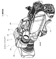
図1、図2はビューファインダー30が装着された撮像装置10の斜視図、図3はディスプレイパネル42の第1の倒伏状態を示す撮像装置10の斜視図、図4はディスプレイパネル42の表示面3402が前方を向いた起立状態を示す撮像装置10の斜視図、図5はディスプレイパネル42の表示面3402が後方を向いた起立状態を示す撮像装置10の斜視図、図6はディスプレイパネル42の第2の倒伏状態を示す撮像装置10の斜視図、図7は撮像装置10の構成を示すブロック図である。
Next, embodiments of the present invention will be described with reference to the drawings.
First, the imaging apparatus of the present embodiment will be described, and then the viewfinder attached to the imaging apparatus will be described.
1 and FIG. 2 are perspective views of the imaging apparatus 10 to which the
本実施の形態において撮像装置10は放送局などで使用される業務用のビデオカメラである。
図1に示すように、撮像装置10は、前後に延在するカメラボディ14を備え、カメラボディ14の前部にレンズ鏡筒12が装着されている。
なお、本明細書において左右は、撮像装置10を後方から見た状態でいうものとし、また、光学系の光軸方向で被写体側を前方といい、撮像素子側を後方という。
レンズ鏡筒12は、撮影光学系16を収容するものである。
撮影光学系16は、被写体像を図7に示す撮像素子14Bに導くものである。なお、撮像素子14Bは、CCD、あるいは、C−MOSセンサなど従来公知のさまざまな撮像素子が採用可能である。
In the present embodiment, the imaging device 10 is a professional video camera used in a broadcasting station or the like.
As shown in FIG. 1, the imaging apparatus 10 includes a
In the present specification, left and right refer to the state in which the imaging device 10 is viewed from the rear, the subject side is referred to as the front in the optical axis direction of the optical system, and the imaging element side is referred to as the rear.
The
The photographing
図1に示すように、カメラボディ14は、外装を構成する筐体18を有している。
筐体18は、前方に臨む前面18A、後方に臨む後面18B、左右側方に臨む左右の側面18C、18D、上方に臨む上面18E、下方に臨む下面18Fを備えている。
本実施の形態では、筐体18は、左右の側面18C、18Dの間の左右方向の幅よりも上面18Eと後面18Fとの間の上下方向の高さが大きい寸法で形成され、この高さよりも前面18Aと後面18Bとの間の前後方向の長さが大きい寸法で形成され、したがって、筐体18は前後に長い直方体状を呈している。
図2に示すように、筐体18の前部には、後述するビューファインダー30を装脱可能に装着するためのカメラ本体側取り付け部19が設けられ、カメラ本体側取り付け部19の後方に持ち運び用のハンドル20が設けられている。
図1に示すように、下面18Eには、撮像装置10を肩に載せるための上方に窪んだ肩パッド22が設けられている。肩パッド22は、弾性および柔軟性を有する部材で形成されている。
As shown in FIG. 1, the
The housing 18 includes a
In the present embodiment, the casing 18 is formed with a dimension in which the height in the vertical direction between the
As shown in FIG. 2, a camera body
As shown in FIG. 1, the
次に、図7を参照してカメラボディ14の制御系の構成について説明する。
図7に示すように、カメラボディ14は、前記の撮像素子14Bの他に、プリズム14A、信号処理部14C、制御部14D、操作部14E、表示部14F、記録再生部14G、I/F部14H、電源部14Iなどを含んで構成されている。
本実施の形態では、3色(赤、緑、青)のそれぞれに対応して3つの撮像素子14Bが設けられており、プリズム14Aは、撮影光学系16から導かれた被写体像を構成する光束を3色(赤、緑、青)に分離して、各色に対応した撮像素子14Bに導くものである。
信号処理部14Cは、各撮像素子14Bを駆動すると共に、各撮像素子14Bから供給される映像信号に対して、例えば、CDS(Correlated Double Sampling)処理を行って、S/N比を良好に保つようにするとともに、AGC(Automatic Gain Control)処理を行って、利得を制御し、さらに、A/D(Analog/Digital)変換を行って、デジタル信号とした映像データを生成するなどの一連の前処理を行い、さらに、前処理がなされた映像データを所定の圧縮方式によって圧縮(エンコード)することにより、前記の記録用の映像データを生成するものである。生成された記録用の映像データは、制御部14Dを介して記録再生部14Gに供給される。
また、信号処理部14Cは、デジタル信号に処理される前のアナログ信号の映像信号をコネクタ14Jを介して後述するビューファインダー30に供給することで撮影中の映像をビューファインダー30に表示させる。また、前記前処理がなされた映像信号をコネクタ14Jを介して外部のディスプレイ装置などに供給することで撮影中の映像を外部のディスプレイ装置に表示させる。
Next, the configuration of the control system of the
As shown in FIG. 7, the
In the present embodiment, three imaging elements 14B are provided corresponding to each of the three colors (red, green, and blue), and the prism 14A is a light beam that forms a subject image guided from the photographing
The
Further, the
記録再生部14Gは、信号処理部14Cから制御部14Dを介して供給される記録用の映像データを、記録媒体に記録し、また、前記記録媒体から再生した映像データを制御部14Dを介してビューファインダー30あるいは外部のディスプレイ装置に供給するものである。
前記記録媒体としては、例えば、磁気記録テープ、光ディスク、あるいは、ハードディスクなどの従来公知のさまざまな記録媒体が利用可能である。
I/F部14Hは、制御部14Dとビューファインダー30との間で前記映像信号の授受やその授受にまつわる制御信号などのやり取りを行うものである。
操作部14Eは、撮像装置10の動作にまつわる種々の設定を行うために操作されるスイッチやボリュームなどで構成されている。
表示部14Fは、撮像装置10の動作状態を表示するディスプレイやLEDランプなどで構成されている。
制御部14Dは、上述した信号処理部14C、I/F部14H、操作部14E、表示部14F、記録再生部14Gの制御を司るものである。
具体的には、制御部14Dは、CPU、ワーキングエリアを提供するRAM、制御プログラムなどを格納するROM、信号処理部14C、I/F部14H、操作部14E、表示部14Fとの間で制御信号やデータ信号を授受するための周辺LSIなどを含むマイクロコンピュータによって構成されており、前記CPUが前記ROMの制御プログラムを実行することによって種々の制御動作を実行する。
The recording / reproducing unit 14G records the recording video data supplied from the
As the recording medium, various conventionally known recording media such as a magnetic recording tape, an optical disk, or a hard disk can be used.
The I / F unit 14H exchanges the video signal between the control unit 14D and the
The operation unit 14E includes a switch and a volume that are operated to perform various settings related to the operation of the imaging apparatus 10.
The
The control unit 14D controls the
Specifically, the control unit 14D controls the CPU, the RAM that provides the working area, the ROM that stores the control program, the
電源部14Iは、不図示の外部電源から供給される電力に基づいて生成した電力を、撮像素子14B、信号処理部14C、I/F部14H、操作部14E、表示部14F、記録再生部14Gに供給することで、それら各部を動作させるものである。また、電源部14Iからの電力はコネクタ14Jを介してビューファインダー30に供給されることでビューファインダー30を動作させるものである。
なお、本実施の形態では、記録再生部14Gがカメラボディ14に内蔵されている場合について説明したが、記録再生部14Gがカメラボディ14の外部に設けられていてもよい。その場合には、記録再生部14Gとカメラボディ14とをケーブルで接続し、ケーブルを介して映像信号などの授受を行うようにすればよい。
The power supply unit 14I generates power generated based on power supplied from an external power source (not shown), the image sensor 14B, the
Although the case where the recording / reproducing unit 14G is built in the
次に、ビューファインダー30について説明する。
図1、図2に示すように、ビューファインダー30は、ディスプレイユニット31と、接眼ユニット36とを含んで構成されている。
ディスプレイユニット31は、本体部32と、ディスプレイ部34とを含んで構成されている。
本体部32には、ディスプレイ部34を動作させるための回路が収容されている。
ディスプレイ部34は表示面3402(図3)を備え、ディスプレイ部34は、カメラボディ14から供給される映像信号に基づいて表示面3402に映像を表示するものである。
接眼ユニット36はディスプレイ部34の表示面3402に表示される映像を拡大表示するものである。
本実施の形態では、ディスプレイ部34は映像を表示する表示装置として液晶ディスプレイ装置を含んで構成されている。
なお、表示装置は液晶ディスプレイ装置に限定されるものではなく、有機ELディスプレイ装置など従来公知のさまざまな表示装置が採用可能である。
Next, the
As shown in FIGS. 1 and 2, the
The
The
The
The
In the present embodiment, the
The display device is not limited to the liquid crystal display device, and various conventionally known display devices such as an organic EL display device can be employed.
図8は本体部32およびディスプレイ部34の斜視図、図9は図8のA矢視図、図10は図8のB矢視図、図11は図8のC矢視図である。
図8に示すように、本体部32は、ケース3202を有し、ケース3202にはカメラボディ側取り付け部19(図2)に装脱可能に装着される本体部側取り付け部3204が設けられている。
本実施の形態では、本体部側取り付け部3204は、本体部32がカメラボディ14に取り付けられた状態で後方に臨む後面に、左右方向に延在形成された係合溝3204Aを含んで構成されている。なお、本体部側取り付け部3204とカメラボディ側取り付け部19と装脱する構成には従来公知のさまざまな構造が採用可能である。
図1、図10に示すように、本体部32がカメラボディ14に取り付けられた状態で、ケース3202が前方に臨む前面に、ディスプレイ部34の動作にまつわる種々の操作を行うための操作部材3210が設けられ、ケース3202が下方に臨む下面にも図示しない操作部材が設けられている。
図10に示すように、ケース3202の前面に設けられた操作部材3210は、複数のボリューム3210A、複数の切り替えスイッチ3210B、複数の押しボタンスイッチ3210Cなどを含んでいる。
また、図5、図8乃至図10に示すように、本体部32がカメラボディ14に取り付けられた状態で、本体部32が左外側方に臨む面は、ディスプレイ部34が連結される連結面3220として形成されている。
8 is a perspective view of the
As shown in FIG. 8, the
In the present embodiment, the main body portion
As shown in FIGS. 1 and 10, an
As shown in FIG. 10, the
In addition, as shown in FIGS. 5 and 8 to 10, the surface of the
ディスプレイ部34は、図8乃至図10に示すように、支持体40と、ディスプレイパネル42と、連結機構60とを含んで構成されている。
支持体40は板状を呈し、本体部32の連結面3220上に回転可能に連結されている。この支持体40は、支軸44を中心に本体部32により揺動可能に支持され、図8において符号L1は支持体40の回転中心(支軸44の軸心)である第1の仮想軸を示し、この第1の仮想軸L1は、本体部32がカメラボディ14に取り付けられた状態で、カメラボディ14の左右方向に延在している。言い換えると、支持体40は本体部32の連結面3220に、カメラボディ14の左右方向に延在する第1の仮想軸L1が支持体40の厚さ方向を通るように配置され、かつ、第1の仮想軸L1を回転中心として揺動可能に連結されている。
なお、支軸44には摩擦抵抗が付与され、支持体40は所望の揺動角度で保持されるように構成されており、このような機構として、摩擦抵抗式のものやクリック機構式のものなど従来公知のさまざまな構造が採用可能である。
支持体40は、上下の高さよりも左右方向の幅が大きい細長形状の板材で形成されている。
As shown in FIGS. 8 to 10, the
The
The
The
図8に示すように、支持体40の長手方向の端部で該長手方向と直交する方向の両側部に軸受け部46がそれぞれ膨出形成されている。
また、図8に示すように、支持体40の長手方向と直交する方向の両側のうちの一方の側部に円弧状の軸受け壁48が設けられ、また、図10に示すように、前記両側のうちの他方の側部に係止凹部50が設けられている。
As shown in FIG. 8,
Further, as shown in FIG. 8, arc-shaped
図8乃至図10に示すように、ディスプレイパネル42は、長方形板状のケース52を有し、ケース52に前記液晶ディスプレイ装置が収容されている。
ケース52は、前面5202と、前面5202の反対側に位置する背面5204とを有している。
前面5202は、開口5206が形成された前面板5210と、開口5206の内側に位置するように設けられた表示面3402とを含んで構成されている。
図10に示すように、2つの軸受け部46の間には、断面が矩形の第1の回転軸54が挿入され、第1の回転軸54の両端の小径軸56が軸受け部46に揺動可能に結合される。
図8、図10において符号L2は第1の回転軸54の軸心であり、第1の回転軸54の回転中心である第2の仮想軸を示す。
本実施の形態では、第2の仮想軸L2は第1の仮想軸L1と直交する平面上を延在している。
図10に示すように、ケース52の2つの短辺のうちの一方の短辺は、第1の回転軸54の延在方向の中間部に対して第2の回転軸58により揺動可能に結合される。
図8、図10において符号L3は第1の回転軸54とケース52とを連結する第2の回転軸58の軸心であり、すなわち、ケース52(ディスプレイパネル42)の回転中心である第3の仮想軸を示す。
本実施の形態では、第3の仮想軸L3は第2の仮想軸L2と直交している。
As shown in FIGS. 8 to 10, the
The
The
As shown in FIG. 10, a first
8 and 10, reference numeral L <b> 2 is the axis of the first
In the present embodiment, the second virtual axis L2 extends on a plane orthogonal to the first virtual axis L1.
As shown in FIG. 10, one short side of the two short sides of the
8 and 10, the symbol L3 is the axis of the
In the present embodiment, the third virtual axis L3 is orthogonal to the second virtual axis L2.
したがって、本実施の形態では、連結機構60は、ディスプレイパネル42の短辺部分と、支持体40の長手方向の端部とを連結しており、本体部32がカメラボディ14に取り付けられた状態で第1の回転軸54は、カメラボディ14の上下方向に延在している。
また、本実施の形態では、軸受け部46、第1の回転軸54、第2の回転軸58などによって連結機構60が構成され、連結機構60は、支持体40とディスプレイパネル42とを第2の仮想軸L2の周りに揺動可能に連結し、かつ、支持体40とディスプレイパネル42とを第3の仮想軸L3の周りに揺動可能に連結している。
連結機構60は、摩擦抵抗が小径軸56に付与されることで第1の回転軸54が第2の仮想軸L2周りにおいて所望の揺動角度で保持されるように構成され、かつ、摩擦抵抗が第2の回転軸58に付与されることでディスプレイパネル42が第3の仮想軸L3周りにおいて所望の揺動角度で保持されるように構成されている。
連結機構60として、このような摩擦抵抗式のものやクリック機構式のものなど従来公知のさまざまな構造が採用可能である。
Therefore, in the present embodiment, the connecting
Further, in the present embodiment, a
The
As the
連結機構60によって、支持体40とディスプレイパネル42とは、図3に示すようにディスプレイパネル42の背面5202が支持体40に臨んだ第1の倒伏状態と、図6に示すようにディスプレイパネル42の表示面3402(前面5204)が支持体40に臨んだ第2の倒伏状態と、図4に示すように支持体40からディスプレイパネル42が起立した起立状態との間で揺動可能となるように連結されている。
第1の倒伏状態は、連結機構60によって、起立状態にあるディスプレイパネル42を第3の仮想軸L3の周りに揺動させディスプレイパネル42を第2の仮想軸L2の周りに揺動させディスプレイパネル42の背面5202を支持体40に重ね合わせることで形成される。
第2の倒伏状態は、連結機構60によって、起立状態にあるディスプレイパネル42を第3の仮想軸L3の周りに揺動させ支持体40に臨ませた状態でディスプレイパネル42を第2の仮想軸L2の周りに揺動させディスプレイパネル42の表示面3402(前面5204)を支持体40に重ね合わせることで形成される。
そして、図3に示すように、本体部32がカメラボディ14に取り付けられた状態において、ディスプレイパネル42が第1の倒伏状態となると、ディスプレイパネル42の表示面3402は、カメラボディ14の左外側方に向く。
また、図6に示すように、本体部32がカメラボディ14に取り付けられた状態において、ディスプレイパネル42が第2の倒伏状態となると、ディスプレイパネル42の背面5202は、カメラボディ14の左外側方に向く。
また、本体部32がカメラボディ14に取り付けられた状態において、ディスプレイパネル42を起立状態として第3の仮想軸L3回りにディスプレイパネル42を揺動することにより、ディスプレイパネル42の表示面3402を前方に向けた状態(図4)と、ディスプレイパネル42の表示面3402を後方に向けた状態(図5)との間で動かすことができる。
By the connecting
In the first lying down state, the
In the second lying down state, the
As shown in FIG. 3, when the
As shown in FIG. 6, when the
In the state where the
図12、図13は接眼ユニット36の斜視図、図14は接眼ユニット36の装着状態を示す平面図、図15は図14のA矢視図、図16は図14のB矢視図である。
図12、図13に示すように、接眼ユニット36は、ミラーおよび複数のレンズを含む光学系3602と、光学系を収容する筒状のハウジング3604と、ハウジング3604の長手方向の一方の端部に設けられた接眼ユニット側取り付け部3606と、ハウジング3604の長手方向の他方の端部に設けられたアイピース3608などを含んで構成されている。
接眼ユニット側取り付け部3606は、表示面3402に対応した大きさの横長の開口3610を有している。
開口3610の周囲に沿って、ディスプレイパネル42の前面板5210を押圧可能な枠部3612が延在形成されている。
また、開口3610の上部には、軸受け壁48に装脱される支軸62が設けられ、開口3610の下部には、係止凹部50に係脱する係止爪64が設けられている。
図14に示すように、接眼ユニット36のディスプレイ部34への装着状態は、第1の倒伏状態において、枠部3612(図12)が前面板5210を押圧することで形成される。
より詳細に説明すると、第1の倒伏状態において、図14に示すように支軸62が軸受け壁48に係合され、図16に示すように係止爪64が係止凹部50に係止される。これにより、図14、図16に示すように枠部3612が前面板5210を押圧し、図14乃至図16に示すように接眼ユニット36のディスプレイ部34への装着状態が形成される。
したがって、接眼ユニット36のディスプレイ部34への装脱を行なう装脱機構が、支軸62、軸受け壁48、係止爪64、係止凹部50により構成されている。また、支持体40に設けられた軸受け壁48と係止凹部50は装脱機構の一部を構成する装脱部となっている。なお、このような装脱機構として従来公知のさまざまな構造が採用可能である。
12 and 13 are perspective views of the
As shown in FIGS. 12 and 13, the
The eyepiece unit
A
A
As shown in FIG. 14, the mounting state of the
More specifically, in the first lying down state, the
Therefore, a loading / unloading mechanism for loading / unloading the
ディスプレイ部34から接眼ユニット36を取り外す際には、ディスプレイ部34に接眼ユニット36が装着された状態で、係止爪64を係止凹部50から外れる方向に操作する。
係止爪64が係止凹部50から外れたならば、支軸62を支点に接眼ユニット36を回動させ、支軸62を軸受け壁48から外す。
これにより、ディスプレイ部34から接眼ユニット36が取り外される。
When the
When the locking
As a result, the
次に、撮像装置10およびビューファインダー30の使用方法について説明する。
図1、図2に示すように、第1の倒伏状態のディスプレイ部34に接眼ユニット36を装着した場合には、撮影者はアイピース3608内を覗くことにより、拡大された表示面3402の映像を視認することができる。
この場合、ディスプレイパネル42および接眼ユニット36を第1の仮想軸L1(図8)を中心に回動させることで撮影アングルを上下方向に任意に変えることができる。
したがって、例えば、撮影者は肩にカメラボディ14の肩パッド22を載せても、カメラボディ14を抱えてもアイピース3608内を楽な姿勢で覗くことができる。
Next, how to use the imaging device 10 and the
As shown in FIGS. 1 and 2, when the
In this case, the shooting angle can be arbitrarily changed in the vertical direction by rotating the
Therefore, for example, even if the photographer places the
また、図3に示すように、第1の倒伏状態のディスプレイ部34から接眼ユニット36を取り外し、図5に示すように、ディスプレイパネル42を第2の仮想軸L2(図8)を中心に揺動させ起立状態としたのち、第3の仮想軸L3(図8)を中心に揺動させて表示面3402を後方に向けた場合、撮影者は肩にカメラボディ14の肩パッド22を載せても表示面3402は後方を向いているので、撮影者は表示面3402を直接肉眼で見ることができる。また、カメラボディ14を抱えてもディスプレイパネル42を第1の仮想軸L1を中心に回転させることができるので、撮影者は表示面3402を楽な姿勢で直接肉眼で見ることができ、したがって、表示面3402を直接肉眼で見ながら撮影アングルを上下方向に変えつつ撮影を行うことも可能となる。
したがって、撮影者はカメラボディ14を肩に載せても抱えてもディスプレイパネル42の表示面3402を楽な姿勢で直接視認しつつ撮影を行うことが可能となる。
Further, as shown in FIG. 3, the
Therefore, the photographer can take a picture while directly viewing the
また、ディスプレイ部34を、図3に示す第1の倒伏状態から第2の仮想軸L2(図8)を中心に揺動させ、図4に示す表示面3402を前方に向けた起立状態とすれば、撮影者は、撮像装置10の前方に位置した状態で、表示面3402に表示される映像を視認しつつ自らの撮影を行え、あるいは、撮影者の後方の被写体の撮影を行うことができる。
Further, the
また、図5に示すように、撮像装置10を携帯する際には、表示面3402を後方に向けた起立状態のディスプレイパネル42を第2の仮想軸L2を中心に揺動させ、図6に示すように、表示面3402を支持体40に重ね合わせた第2の倒伏状態とすることで、ディスプレイパネル42がカメラボディ14上に占有するスペースが縮小される。
Further, as shown in FIG. 5, when the imaging apparatus 10 is carried, the standing
本実施の形態によれば、ディスプレイ部34から接眼ユニット36を取り外してディスプレイパネル42の表示面3402を直接視認する場合、ディスプレイパネル42を起立状態にでき、しかも、起立状態としたディスプレイパネル42を本体部32上で回転できるので、撮影者は不自然な姿勢を強いられることがなく、ディスプレイパネル42の表示面3402を視認しやすく、自由に撮影アングルを変えることができ、使い勝手の向上を図る上で有利となる。
また、本実施の形態によれば、ディスプレイ部34を第2の倒伏状態とすれば、撮像装置10をコンパクト化でき携帯性を高める上で有利となることは無論のこと、かつ、表示面3402が支持体40に重ね合わされて外方に露出しない状態となるので、表示面3402の保護を図る上でも有利となる。
According to the present embodiment, when the
Further, according to the present embodiment, if the
また、本実施の形態では、ディスプレイパネル42は支持体40を介して第1の仮想軸L1を中心として揺動するため、起立状態にあるディスプレイパネル42は、本体部32の前端に位置する前方位置と、本体部32の後端に位置する後方位置とに選択的に位置させることができる。
そして、ディスプレイパネル42は第3の仮想軸L3を中心として揺動するため、ディスプレイパネル42は、前方位置と後方位置との双方において表示面3402を後方に向けた状態とすることができる。
したがって、撮影者が肩にカメラボディ14の肩パッド22を載せてディスプレイパネル42の表示面3402を視認する場合、ディスプレイパネル42を前方位置あるいは後方位置に動かすことで、撮影者の眼と表示面3402との間の距離を調整することができ、撮影者の視力や撮影姿勢に応じて撮影者の眼と表示面3402との間の距離を調整することができ使い勝手を高める上で有利となる。
In the present embodiment, the
Since the
Therefore, when the photographer places the
なお、本実施の形態では、撮像装置10のカメラボディ14に装脱可能に装着に装着されるビューファインダー30について説明したが、ビューファインダー30の本体部32がカメラボディ14に一体的に設けられていてもよく、そのような撮像装置10についても本発明は無論適用される。
In the present embodiment, the
10……撮像装置、14……カメラボディ、30……ビューファインダー、32……本体部、34……ディスプレイ部、3402……表示面、36……接眼ユニット、40……支持体、42……ディスプレイパネル、60……連結機構。 DESCRIPTION OF SYMBOLS 10 ... Imaging device, 14 ... Camera body, 30 ... Viewfinder, 32 ... Main part, 34 ... Display part, 3402 ... Display surface, 36 ... Eyepiece unit, 40 ... Support, 42 ... ... display panel, 60 ... connection mechanism.
Claims (11)
前記カメラボディ側で撮像する映像が表示されるディスプレイ部と、
前記ディスプレイ部に装脱可能に装着され前記ディスプレイ部で表示された映像を拡大する接眼ユニットとを備え、
前記ディスプレイ部は、前記接眼ユニットとの装脱部が設けられた板状の支持体と、ディスプレイパネルと、連結機構とを有し、
前記支持体は、前記カメラボディに装着された前記本体部に、前記カメラボディの左右方向に延在する第1の仮想軸が該支持体の厚さ方向を通るように配置され、かつ、前記第1の仮想軸を回転中心として揺動可能に連結され、
前記ディスプレイパネルは、前記映像が表示される表示面を有し、
前記連結機構は、前記支持体の端部と前記ディスプレイパネルの端部とを、前記第1の仮想軸と直交する平面上を延在する第2の仮想軸を回転中心として揺動可能に連結すると共に、前記第2の仮想軸に直交する第3の仮想軸を回転中心として揺動可能に連結し、前記ディスプレイパネルを、前記支持体に前記ディスプレイパネルの前記表示面と反対に位置する背面が重ね合わされた第1の倒伏状態と、前記支持体に前記ディスプレイパネルの表示面が重ね合わされた第2の倒伏状態と、前記支持体から前記ディスプレイパネルが起立した起立状態とする、
ことを特徴とするビューファインダー。 A main body that is detachably attached to the camera body extending forward and backward ,
A display unit on which an image captured on the camera body side is displayed;
An eyepiece unit that is detachably attached to the display unit and expands an image displayed on the display unit,
The display unit includes a plate-like support body provided with a loading / unloading unit with the eyepiece unit, a display panel, and a coupling mechanism.
The support is disposed on the main body mounted on the camera body such that a first virtual axis extending in the left-right direction of the camera body passes through the thickness direction of the support, and The first imaginary axis is pivotally connected around the rotation center ,
The display panel may have a display surface on which the image is displayed,
The connection mechanism connects the end of the support and the end of the display panel so as to be swingable about a second virtual axis extending on a plane orthogonal to the first virtual axis. And a back surface that is slidably connected with a third virtual axis orthogonal to the second virtual axis as a center of rotation, and the display panel is positioned on the support opposite to the display surface of the display panel. A first lying state in which the display panel is superimposed on the support body, a second lying state in which the display surface of the display panel is superimposed on the support body, and an upright state in which the display panel stands up from the support body ,
A viewfinder characterized by that .
ことを特徴とする請求項1記載のビューファインダー。 Wherein the connecting mechanism, the swing and the display panel and the support member, a first rotary shaft for swingably connected as a rotation about the second imaginary axis, as the center of rotation of said third imaginary axis And a second rotation shaft that can be coupled to each other.
The viewfinder according to claim 1.
前記第2の倒伏状態は、前記起立状態において前記ディスプレイパネルを前記第3の仮想軸の周りに揺動させたのち、前記ディスプレイパネルを前記第2の仮想軸の周りに揺動させて前記表示面を前記支持体に重ね合わせることにより形成される、
ことを特徴とする請求項2記載のビューファインダー。 In the first lying down state, the display panel is swung around the third virtual axis in the standing state, and then the display panel is swung around the second virtual axis. Formed on the support,
In the second lying down state, the display panel is swung around the third virtual axis in the standing state, and then the display panel is swung around the second virtual axis. Formed by superimposing a surface on the support,
The viewfinder according to claim 2, wherein
前記連結機構により前記ディスプレイパネルの端部に連結される前記支持体の端部は、前記支持体の長手方向の端部である、
ことを特徴とする請求項1記載のビューファインダー。 The support has an elongated shape having a width larger than the height,
The end of the support connected to the end of the display panel by the connection mechanism is an end in the longitudinal direction of the support .
The viewfinder according to claim 1.
前記ディスプレイパネルは、長方形を呈し、
前記連結機構は、前記ディスプレイパネルの短辺部分と、前記支持体の長手方向の端部とを連結している、
ことを特徴とする請求項1記載のビューファインダー。 The support has an elongated shape having a width larger than the height,
The display panel has a rectangular shape,
The connection mechanism connects the short side portion of the display panel and the end portion in the longitudinal direction of the support,
The viewfinder according to claim 1.
前記第1、第2の倒伏状態で、前記ディスプレイパネルと前記支持体は平行し、前記起立状態で、前記ディスプレイパネルは前記支持体に対して直交する、
ことを特徴とする請求項1記載のビューファインダー。 The display panel has a plate shape,
In the first and second lying down states, the display panel and the support are parallel, and in the standing state, the display panel is orthogonal to the support.
The viewfinder according to claim 1.
前記装脱部は前記装脱機構の一部を構成している、
ことを特徴とする請求項1記載のビューファインダー。 The eyepiece unit of instrumentation de mechanism for attaching and detaching to the display unit is provided, et al is,
The loading / unloading part constitutes a part of the loading / unloading mechanism,
The viewfinder according to claim 1.
前記カメラボディに設けられたビューファインダーとを備え、
前記ビューファインダーは、
カメラボディに装脱可能に装着される本体部と、
前記カメラボディ側で撮像する映像が表示されるディスプレイ部と、
前記ディスプレイ部に装脱可能に装着され前記ディスプレイ部で表示された映像を拡大する接眼ユニットとを備え、
前記ディスプレイ部は、前記接眼ユニットとの装脱部が設けられた板状の支持体と、ディスプレイパネルと、連結機構とを有し、
前記支持体は、前記カメラボディに装着された前記本体部に、前記カメラボディの左右方向に延在する第1の仮想軸が該支持体の厚さ方向を通るように配置され、かつ、前記第1の仮想軸を回転中心として揺動可能に連結され、
前記ディスプレイパネルは、前記映像が表示される表示面を有し、
前記連結機構は、前記支持体の端部と前記ディスプレイパネルの端部とを、前記第1の仮想軸と直交する平面上を延在する第2の仮想軸を回転中心として揺動可能に連結すると共に、前記第2の仮想軸に直交する第3の仮想軸を回転中心として揺動可能に連結し、前記ディスプレイパネルを、前記支持体に前記ディスプレイパネルの前記表示面と反対に位置する背面が重ね合わされた第1の倒伏状態と、前記支持体に前記ディスプレイパネルの表示面が重ね合わされた第2の倒伏状態と、前記支持体から前記ディスプレイパネルが起立した起立状態とする、
ことを特徴とする撮像装置。 A camera body that extends back and forth to capture images,
A viewfinder provided on the camera body,
The viewfinder is
A main body that is detachably attached to the camera body;
A display unit on which an image captured on the camera body side is displayed;
An eyepiece unit that is detachably attached to the display unit and expands an image displayed on the display unit,
The display unit includes a plate-like support body provided with a loading / unloading unit with the eyepiece unit, a display panel, and a coupling mechanism.
The support is disposed on the main body mounted on the camera body such that a first virtual axis extending in the left-right direction of the camera body passes through the thickness direction of the support, and The first imaginary axis is pivotally connected around the rotation center ,
The display panel may have a display surface on which the image is displayed,
The connection mechanism connects the end of the support and the end of the display panel so as to be swingable about a second virtual axis extending on a plane orthogonal to the first virtual axis. And a back surface that is slidably connected with a third virtual axis orthogonal to the second virtual axis as a center of rotation, and the display panel is positioned on the support opposite to the display surface of the display panel. A first lying state in which the display panel is superimposed on the support body, a second lying state in which the display surface of the display panel is superimposed on the support body, and an upright state in which the display panel stands up from the support body ,
An imaging apparatus characterized by that.
ことを特徴とする請求項8記載の撮像装置。 Wherein the connecting mechanism, the swing and the display panel and the support member, a first rotary shaft for swingably connected as a rotation about the second imaginary axis, as the center of rotation of said third imaginary axis And a second rotation shaft that can be coupled to each other.
The imaging apparatus according to claim 8.
ことを特徴とする請求項8記載の撮像装置。 In the first lying state, the display surface is directed to the left and right sides of the camera body, and in the second lying state, the back surface is directed to the left and right sides of the camera body. Is oriented in the front-back direction or up-down direction,
The imaging apparatus according to claim 8.
前記カメラボディに設けられたビューファインダーとを備え、
前記ビューファインダーは、
前記カメラボディに一体的に設けられた本体部と、
前記カメラボディ側で撮像する映像が表示されるディスプレイ部と、
前記ディスプレイ部に装脱可能に装着され前記ディスプレイ部で表示された映像を拡大する接眼ユニットとを備え、
前記ディスプレイ部は、前記接眼ユニットとの装脱部が設けられた板状の支持体と、ディスプレイパネルと、連結機構とを有し、
前記支持体は、前記本体部に、前記カメラボディの左右方向に延在する第1の仮想軸が該支持体の厚さ方向を通るように配置され、かつ、前記第1の仮想軸を回転中心として揺動可能に連結され、
前記ディスプレイパネルは、前記映像が表示される表示面を有し、
前記連結機構は、前記支持体の端部と前記ディスプレイパネルの端部とを、前記第1の仮想軸と直交する平面上を延在する第2の仮想軸を回転中心として揺動可能に連結すると共に、前記第2の仮想軸に直交する第3の仮想軸を回転中心として揺動可能に連結し、前記ディスプレイパネルを、前記支持体に前記ディスプレイパネルの前記表示面と反対に位置する背面が重ね合わされた第1の倒伏状態と、前記支持体に前記ディスプレイパネルの表示面が重ね合わされた第2の倒伏状態と、前記支持体から前記ディスプレイパネルが起立した起立状態とする、
ことを特徴とする撮像装置。 A camera body that extends back and forth to capture images,
A viewfinder provided on the camera body,
The viewfinder is
A main body provided integrally with the camera body;
A display unit on which an image captured on the camera body side is displayed;
An eyepiece unit that is detachably attached to the display unit and expands an image displayed on the display unit,
The display unit includes a plate-like support body provided with a loading / unloading unit with the eyepiece unit, a display panel, and a coupling mechanism.
The support is disposed on the main body so that a first virtual axis extending in the left-right direction of the camera body passes through the thickness direction of the support, and rotates the first virtual axis. It is pivotably connected as the center ,
The display panel may have a display surface on which the image is displayed,
The connection mechanism connects the end of the support and the end of the display panel so as to be swingable about a second virtual axis extending on a plane orthogonal to the first virtual axis. And a back surface that is slidably connected with a third virtual axis orthogonal to the second virtual axis as a center of rotation, and the display panel is positioned on the support opposite to the display surface of the display panel. A first lying state in which the display panel is superimposed on the support body, a second lying state in which the display surface of the display panel is superimposed on the support body, and an upright state in which the display panel stands up from the support body ,
An imaging apparatus characterized by that.
Priority Applications (2)
| Application Number | Priority Date | Filing Date | Title |
|---|---|---|---|
| JP2007132370A JP4315213B2 (en) | 2007-05-18 | 2007-05-18 | Viewfinder and imaging device |
| US12/120,973 US7956922B2 (en) | 2007-05-18 | 2008-05-15 | Viewfinder and image pickup apparatus |
Applications Claiming Priority (1)
| Application Number | Priority Date | Filing Date | Title |
|---|---|---|---|
| JP2007132370A JP4315213B2 (en) | 2007-05-18 | 2007-05-18 | Viewfinder and imaging device |
Publications (2)
| Publication Number | Publication Date |
|---|---|
| JP2008288920A JP2008288920A (en) | 2008-11-27 |
| JP4315213B2 true JP4315213B2 (en) | 2009-08-19 |
Family
ID=40027093
Family Applications (1)
| Application Number | Title | Priority Date | Filing Date |
|---|---|---|---|
| JP2007132370A Expired - Fee Related JP4315213B2 (en) | 2007-05-18 | 2007-05-18 | Viewfinder and imaging device |
Country Status (2)
| Country | Link |
|---|---|
| US (1) | US7956922B2 (en) |
| JP (1) | JP4315213B2 (en) |
Families Citing this family (7)
| Publication number | Priority date | Publication date | Assignee | Title |
|---|---|---|---|---|
| DE102013218222A1 (en) * | 2013-09-11 | 2015-03-12 | Arnold & Richter Cine Technik Gmbh & Co. Betriebs Kg | Viewfinder and control unit |
| JP1540708S (en) * | 2015-03-09 | 2015-12-28 | ||
| USD797177S1 (en) * | 2015-04-08 | 2017-09-12 | Blackmagic Design Pty Ltd | Electronic view finder |
| JP5848484B1 (en) * | 2015-07-24 | 2016-01-27 | 稔 稲葉 | Digital camera |
| US10732491B2 (en) | 2017-03-24 | 2020-08-04 | Canon Kabushiki Kaisha | Image pickup apparatus to which accessory is removably attached, and image pickup system |
| JP6639448B2 (en) * | 2017-03-24 | 2020-02-05 | キヤノン株式会社 | Imaging device and imaging system |
| JP1613026S (en) * | 2017-12-28 | 2018-09-10 |
Family Cites Families (15)
| Publication number | Priority date | Publication date | Assignee | Title |
|---|---|---|---|---|
| US4757388A (en) * | 1985-08-09 | 1988-07-12 | Canon Kabushiki Kaisha | Camera with electronic view finder viewable from either behind or in front of the camera |
| JPH0583608A (en) | 1991-09-20 | 1993-04-02 | Canon Inc | Finder device |
| KR0136059B1 (en) * | 1994-03-10 | 1998-04-27 | 구자홍 | Apparatus for fixing lcd view-finder to camcorder |
| KR0113218Y1 (en) * | 1994-11-25 | 1998-04-13 | 이헌조 | Handgrip unified l.c.d. for camcordr |
| US5790193A (en) * | 1995-11-22 | 1998-08-04 | Eastman Kodak Company | Accessory module for an electronic camera |
| JPH10322575A (en) | 1997-04-30 | 1998-12-04 | Samsung Electron Co Ltd | Video camera with liquid crystal monitor |
| FR2792148B1 (en) * | 1999-04-07 | 2002-12-27 | Thomson Broadcast Systems | VIDEO CAMERA WITH FLAT SCREEN VIEWFINDER |
| JP2004147233A (en) * | 2002-10-25 | 2004-05-20 | Sony Corp | Video camera |
| JP2004147232A (en) | 2002-10-25 | 2004-05-20 | Sony Corp | View finder and video camera |
| KR20050055481A (en) * | 2003-12-08 | 2005-06-13 | 삼성전자주식회사 | Camcorder having a connecting/seperating display unit |
| KR20050066305A (en) * | 2003-12-26 | 2005-06-30 | 삼성전자주식회사 | Image photographing apparatus having appearing and disappearing lens unit |
| US20060082682A1 (en) * | 2004-10-15 | 2006-04-20 | Hoodman Corporation | Camera LCD screen viewing device |
| JP4174736B2 (en) * | 2006-08-24 | 2008-11-05 | ソニー株式会社 | Imaging device and lock mechanism |
| JP2008205535A (en) * | 2007-02-16 | 2008-09-04 | Sony Corp | Viewfinder and control method thereof, and imaging apparatus |
| JP4432982B2 (en) * | 2007-02-16 | 2010-03-17 | ソニー株式会社 | Viewfinder and imaging device |
-
2007
- 2007-05-18 JP JP2007132370A patent/JP4315213B2/en not_active Expired - Fee Related
-
2008
- 2008-05-15 US US12/120,973 patent/US7956922B2/en not_active Expired - Fee Related
Also Published As
| Publication number | Publication date |
|---|---|
| US7956922B2 (en) | 2011-06-07 |
| US20080284895A1 (en) | 2008-11-20 |
| JP2008288920A (en) | 2008-11-27 |
Similar Documents
| Publication | Publication Date | Title |
|---|---|---|
| JP4432982B2 (en) | Viewfinder and imaging device | |
| JP4315213B2 (en) | Viewfinder and imaging device | |
| US6445417B1 (en) | Video still camera with a lens unit rotation device | |
| JP2005260959A (en) | Image pickup device | |
| JP2006129391A (en) | Imaging apparatus | |
| JP2002044494A (en) | Digital camera | |
| JP2003309634A5 (en) | ||
| JP2006237774A (en) | Camera system | |
| JP2002062578A (en) | Photographing holder for camera | |
| JP4307484B2 (en) | Imaging device | |
| JP2008205535A (en) | Viewfinder and control method thereof, and imaging apparatus | |
| JP4481673B2 (en) | Digital camera | |
| JPH11261858A (en) | Image pickup device | |
| JP2008205532A (en) | Viewfinder and imaging apparatus | |
| JP2807616B2 (en) | Camera-integrated recording device with monitor | |
| JP4262277B2 (en) | Imaging device | |
| JP4453550B2 (en) | Imaging device | |
| JP2006314042A (en) | Digital camera | |
| JP2008148341A (en) | Imaging apparatus | |
| JP2010026090A (en) | External type monitoring device and system of camera | |
| JP4264559B2 (en) | Shooting system and interface box | |
| JP2003110885A (en) | Camera | |
| JP2005079760A (en) | Connection device for electronic equipment | |
| JP3930471B2 (en) | Video shooting device | |
| JP2005109711A (en) | Portable camera |
Legal Events
| Date | Code | Title | Description |
|---|---|---|---|
| A977 | Report on retrieval |
Free format text: JAPANESE INTERMEDIATE CODE: A971007 Effective date: 20090218 |
|
| A131 | Notification of reasons for refusal |
Free format text: JAPANESE INTERMEDIATE CODE: A131 Effective date: 20090224 |
|
| A521 | Request for written amendment filed |
Free format text: JAPANESE INTERMEDIATE CODE: A523 Effective date: 20090331 |
|
| TRDD | Decision of grant or rejection written | ||
| A01 | Written decision to grant a patent or to grant a registration (utility model) |
Free format text: JAPANESE INTERMEDIATE CODE: A01 Effective date: 20090428 |
|
| A01 | Written decision to grant a patent or to grant a registration (utility model) |
Free format text: JAPANESE INTERMEDIATE CODE: A01 |
|
| A61 | First payment of annual fees (during grant procedure) |
Free format text: JAPANESE INTERMEDIATE CODE: A61 Effective date: 20090511 |
|
| FPAY | Renewal fee payment (event date is renewal date of database) |
Free format text: PAYMENT UNTIL: 20120529 Year of fee payment: 3 |
|
| FPAY | Renewal fee payment (event date is renewal date of database) |
Free format text: PAYMENT UNTIL: 20130529 Year of fee payment: 4 |
|
| R250 | Receipt of annual fees |
Free format text: JAPANESE INTERMEDIATE CODE: R250 |
|
| R250 | Receipt of annual fees |
Free format text: JAPANESE INTERMEDIATE CODE: R250 |
|
| LAPS | Cancellation because of no payment of annual fees |