JP4310421B2 - A tiled retroreflective sheet consisting of cube corner elements with steep slopes - Google Patents
A tiled retroreflective sheet consisting of cube corner elements with steep slopes Download PDFInfo
- Publication number
- JP4310421B2 JP4310421B2 JP50709199A JP50709199A JP4310421B2 JP 4310421 B2 JP4310421 B2 JP 4310421B2 JP 50709199 A JP50709199 A JP 50709199A JP 50709199 A JP50709199 A JP 50709199A JP 4310421 B2 JP4310421 B2 JP 4310421B2
- Authority
- JP
- Japan
- Prior art keywords
- cube corner
- retroreflective
- sheet
- angle
- array
- Prior art date
- Legal status (The legal status is an assumption and is not a legal conclusion. Google has not performed a legal analysis and makes no representation as to the accuracy of the status listed.)
- Expired - Fee Related
Links
- 238000005286 illumination Methods 0.000 claims description 33
- 239000000758 substrate Substances 0.000 claims description 8
- 239000000463 material Substances 0.000 description 34
- 230000003287 optical effect Effects 0.000 description 29
- 238000000034 method Methods 0.000 description 16
- 238000003491 array Methods 0.000 description 14
- 238000004519 manufacturing process Methods 0.000 description 12
- 238000000465 moulding Methods 0.000 description 9
- PXHVJJICTQNCMI-UHFFFAOYSA-N Nickel Chemical compound [Ni] PXHVJJICTQNCMI-UHFFFAOYSA-N 0.000 description 6
- 238000000576 coating method Methods 0.000 description 6
- 238000003754 machining Methods 0.000 description 5
- 239000004005 microsphere Substances 0.000 description 5
- 230000003014 reinforcing effect Effects 0.000 description 5
- 238000007789 sealing Methods 0.000 description 5
- 230000008859 change Effects 0.000 description 4
- 238000005520 cutting process Methods 0.000 description 4
- 230000007423 decrease Effects 0.000 description 4
- 229920000515 polycarbonate Polymers 0.000 description 4
- 239000004417 polycarbonate Substances 0.000 description 4
- 238000012545 processing Methods 0.000 description 4
- 230000004044 response Effects 0.000 description 4
- 239000000853 adhesive Substances 0.000 description 3
- 230000001070 adhesive effect Effects 0.000 description 3
- 239000003795 chemical substances by application Substances 0.000 description 3
- 238000005516 engineering process Methods 0.000 description 3
- 229910052759 nickel Inorganic materials 0.000 description 3
- 229920003229 poly(methyl methacrylate) Polymers 0.000 description 3
- 229920000642 polymer Polymers 0.000 description 3
- 229920002635 polyurethane Polymers 0.000 description 3
- 239000004814 polyurethane Substances 0.000 description 3
- -1 vinyl halide Chemical class 0.000 description 3
- 150000001252 acrylic acid derivatives Chemical class 0.000 description 2
- 229910052782 aluminium Inorganic materials 0.000 description 2
- XAGFODPZIPBFFR-UHFFFAOYSA-N aluminium Chemical compound [Al] XAGFODPZIPBFFR-UHFFFAOYSA-N 0.000 description 2
- 239000011324 bead Substances 0.000 description 2
- 230000008901 benefit Effects 0.000 description 2
- 230000005540 biological transmission Effects 0.000 description 2
- 230000015572 biosynthetic process Effects 0.000 description 2
- 239000011248 coating agent Substances 0.000 description 2
- 238000013461 design Methods 0.000 description 2
- 229910003460 diamond Inorganic materials 0.000 description 2
- 239000010432 diamond Substances 0.000 description 2
- 229920000554 ionomer Polymers 0.000 description 2
- 229910052751 metal Inorganic materials 0.000 description 2
- 239000002184 metal Substances 0.000 description 2
- 229920000728 polyester Polymers 0.000 description 2
- 229920000573 polyethylene Polymers 0.000 description 2
- 239000004926 polymethyl methacrylate Substances 0.000 description 2
- 238000000820 replica moulding Methods 0.000 description 2
- 238000012360 testing method Methods 0.000 description 2
- 229920001187 thermosetting polymer Polymers 0.000 description 2
- 238000007740 vapor deposition Methods 0.000 description 2
- 229910001369 Brass Inorganic materials 0.000 description 1
- RYGMFSIKBFXOCR-UHFFFAOYSA-N Copper Chemical compound [Cu] RYGMFSIKBFXOCR-UHFFFAOYSA-N 0.000 description 1
- 229910001335 Galvanized steel Inorganic materials 0.000 description 1
- 241001325354 Lamiinae Species 0.000 description 1
- 241000761557 Lamina Species 0.000 description 1
- VVQNEPGJFQJSBK-UHFFFAOYSA-N Methyl methacrylate Chemical compound COC(=O)C(C)=C VVQNEPGJFQJSBK-UHFFFAOYSA-N 0.000 description 1
- 229920005372 Plexiglas® Polymers 0.000 description 1
- 239000004952 Polyamide Substances 0.000 description 1
- 239000004698 Polyethylene Substances 0.000 description 1
- 229920003182 Surlyn® Polymers 0.000 description 1
- 239000006096 absorbing agent Substances 0.000 description 1
- 239000002253 acid Substances 0.000 description 1
- 229920006397 acrylic thermoplastic Polymers 0.000 description 1
- 239000000654 additive Substances 0.000 description 1
- 125000001931 aliphatic group Chemical group 0.000 description 1
- 125000003118 aryl group Chemical group 0.000 description 1
- 230000000712 assembly Effects 0.000 description 1
- 238000000429 assembly Methods 0.000 description 1
- 230000004888 barrier function Effects 0.000 description 1
- 230000001588 bifunctional effect Effects 0.000 description 1
- 239000010951 brass Substances 0.000 description 1
- 238000005266 casting Methods 0.000 description 1
- 230000015556 catabolic process Effects 0.000 description 1
- 229920006217 cellulose acetate butyrate Polymers 0.000 description 1
- 238000003486 chemical etching Methods 0.000 description 1
- 239000003086 colorant Substances 0.000 description 1
- 239000002131 composite material Substances 0.000 description 1
- 239000000356 contaminant Substances 0.000 description 1
- 229910052802 copper Inorganic materials 0.000 description 1
- 239000010949 copper Substances 0.000 description 1
- 238000006731 degradation reaction Methods 0.000 description 1
- 230000000593 degrading effect Effects 0.000 description 1
- 238000009826 distribution Methods 0.000 description 1
- 230000009977 dual effect Effects 0.000 description 1
- 239000000975 dye Substances 0.000 description 1
- 229920001971 elastomer Polymers 0.000 description 1
- 239000000806 elastomer Substances 0.000 description 1
- 238000004070 electrodeposition Methods 0.000 description 1
- 238000005323 electroforming Methods 0.000 description 1
- 238000004049 embossing Methods 0.000 description 1
- 229920001038 ethylene copolymer Polymers 0.000 description 1
- 239000012530 fluid Substances 0.000 description 1
- 239000008397 galvanized steel Substances 0.000 description 1
- 230000001788 irregular Effects 0.000 description 1
- 238000002372 labelling Methods 0.000 description 1
- 238000010030 laminating Methods 0.000 description 1
- 230000004446 light reflex Effects 0.000 description 1
- 238000005259 measurement Methods 0.000 description 1
- 150000002739 metals Chemical class 0.000 description 1
- 238000003801 milling Methods 0.000 description 1
- 239000002245 particle Substances 0.000 description 1
- 239000000049 pigment Substances 0.000 description 1
- 229920003023 plastic Polymers 0.000 description 1
- 239000004033 plastic Substances 0.000 description 1
- 229920002647 polyamide Polymers 0.000 description 1
- 229920001896 polybutyrate Polymers 0.000 description 1
- 229920006289 polycarbonate film Polymers 0.000 description 1
- 229920000139 polyethylene terephthalate Polymers 0.000 description 1
- 239000005020 polyethylene terephthalate Substances 0.000 description 1
- 229920000915 polyvinyl chloride Polymers 0.000 description 1
- 239000004800 polyvinyl chloride Substances 0.000 description 1
- 229920002620 polyvinyl fluoride Polymers 0.000 description 1
- 230000000644 propagated effect Effects 0.000 description 1
- 230000005855 radiation Effects 0.000 description 1
- 230000009467 reduction Effects 0.000 description 1
- 239000002990 reinforced plastic Substances 0.000 description 1
- 239000012779 reinforcing material Substances 0.000 description 1
- 230000010076 replication Effects 0.000 description 1
- 230000035936 sexual power Effects 0.000 description 1
- ISXSCDLOGDJUNJ-UHFFFAOYSA-N tert-butyl prop-2-enoate Chemical compound CC(C)(C)OC(=O)C=C ISXSCDLOGDJUNJ-UHFFFAOYSA-N 0.000 description 1
- 229920001169 thermoplastic Polymers 0.000 description 1
- 239000004416 thermosoftening plastic Substances 0.000 description 1
- 229920002554 vinyl polymer Polymers 0.000 description 1
- 238000003466 welding Methods 0.000 description 1
Images


Classifications
-
- G—PHYSICS
- G02—OPTICS
- G02B—OPTICAL ELEMENTS, SYSTEMS OR APPARATUS
- G02B5/00—Optical elements other than lenses
- G02B5/12—Reflex reflectors
- G02B5/122—Reflex reflectors cube corner, trihedral or triple reflector type
- G02B5/124—Reflex reflectors cube corner, trihedral or triple reflector type plural reflecting elements forming part of a unitary plate or sheet
-
- B—PERFORMING OPERATIONS; TRANSPORTING
- B29—WORKING OF PLASTICS; WORKING OF SUBSTANCES IN A PLASTIC STATE IN GENERAL
- B29D—PRODUCING PARTICULAR ARTICLES FROM PLASTICS OR FROM SUBSTANCES IN A PLASTIC STATE
- B29D11/00—Producing optical elements, e.g. lenses or prisms
- B29D11/00634—Production of filters
-
- Y—GENERAL TAGGING OF NEW TECHNOLOGICAL DEVELOPMENTS; GENERAL TAGGING OF CROSS-SECTIONAL TECHNOLOGIES SPANNING OVER SEVERAL SECTIONS OF THE IPC; TECHNICAL SUBJECTS COVERED BY FORMER USPC CROSS-REFERENCE ART COLLECTIONS [XRACs] AND DIGESTS
- Y10—TECHNICAL SUBJECTS COVERED BY FORMER USPC
- Y10S—TECHNICAL SUBJECTS COVERED BY FORMER USPC CROSS-REFERENCE ART COLLECTIONS [XRACs] AND DIGESTS
- Y10S425/00—Plastic article or earthenware shaping or treating: apparatus
- Y10S425/808—Lens mold
Landscapes
- Physics & Mathematics (AREA)
- General Physics & Mathematics (AREA)
- Optics & Photonics (AREA)
- Engineering & Computer Science (AREA)
- Health & Medical Sciences (AREA)
- Manufacturing & Machinery (AREA)
- Ophthalmology & Optometry (AREA)
- Mechanical Engineering (AREA)
- Optical Elements Other Than Lenses (AREA)
Description
発明の分野
本発明は、概して、シートの主要面に垂直の軸を中心とするシートの回転方向付けに関係なく、相対的に大きな照射角で入射する光の相当の割合を送り返す能力を有するキューブコーナ再帰反射性シートに関する。
発明の背景
再帰反射性材料は、入射光を発光源に向かって再び誘導することによって特徴づけられる。この特性は、種々の人目を引く用途で再帰反射性シートの使用の普及をもたらしてきた。再帰反射性シートは、例えば、悪い照明状態で道路標識とバリケードのような平坦で剛性の物品をより目立ちやすくするために、それら物品に利用される。再帰反射性シートは不規則または可撓性の表面にも使用される。例えば、再帰反射性シートは、波形物と突出リベットとを覆うためにシートを必要とする貨物トレーラの側面に接着することができるか、あるいはシートは道路作業者の安全ベストまたは他のこのような安全服のような可撓性の本体部分に接着することができる。
多くの人目を引くための用途は、再帰反射性シートに関する特定の性能標準によって左右される。製造業者は、市場の供給者として見なされるためには、それらの再帰反射性シートが関連の性能標準を満足する能力を有することを示さなければならない。再帰反射の説明(ASTM指示E808−93b、再帰反射の説明のための標準試験を参照)および再帰反射体の測定の両方について、標準のボディが存在する。(ASTM指示E809−94a、再帰反射体の測光特性の測定に関する標準試験参照)。
2つの既知の型式の再帰反射性シートは微小球ベースのシートとキューブコーナシートである。微小球ベースのシート(時に「ビード付き」シートと呼ばれる)は、結合層に少なくとも部分的に典型的に埋め込まれると共に入射光を再帰反射するために関連の正反射または散乱反射材料(例えば顔料粒子、メタルフレイクまたは蒸着被覆等)を有する微小球群を用いる。例示目的の実例が、米国特許第3,190,178号(McKenzie)、第4,025,159号(McGrath)および第5,066,098号(Kult)に開示されている。ビード付きの再帰反射体の対称性により、微小球ベースのシートは、シート面に垂直な軸線の周りを回転する時、相対的に均一な入射角性を示す。したがって、ビード付きシートの再帰反射性性能が、対象物の表面にシートが配置される方向付けから受ける影響は相対的に小さい。しかし、概して、微小球ベースのシートは相対的に低い再帰反射性効率を示す。ビード付きの再帰反射性シートは、典型的に、約2°の角度の観測円錐で約5%〜15%の全光再帰を示す。
キューブコーナ再帰反射性シートは、ほぼ平坦な基部面と、基部面と反対側に複数のキューブコーナ要素を備えた構造化表面とを典型的に有する本体部分を備える。各キューブコーナ要素は、単一の基準点あるいは頂点で典型的に交差する相互にほぼ垂直の3つの光学面を備える。キューブコーナ要素の基部は、光がキューブコーナ要素内に伝播される開口として働く。使用時、シートの基部面に入射する光はシートの基部面で屈折し、シート上配設するキューブコーナ要素のそれぞれの基部を通して伝播され、3つの垂直のキューブコーナ光学面の各々から反射され、また光源に向かって再び導かれる。
多くの性能標準の1つの観点は、種々の照射角でシート面に入射する光の特定の割合を送り返すために再帰反射性シートを必要とする。入射光の照射角の関数としての再帰反射性シートの全光再帰特性は、概して当業者ではシートの「入射角性」と呼ばれる。相対的に大きな照射角で入射する光の相当の割合を送り返す能力を有する再帰反射性シートは、米国特許第4,588,258(Hoopman)の同一明度曲線に開示されているような、強いかまたは幅の広い入射角性を有するものとして特徴づけることができる。
それに反して、低い入射角性を有する再帰反射性シートは、入射角が0°から逸脱するにつれて、急速にその再帰反射性輝度を失う(全光再帰は減少する)。さらに、入射角性は典型的に約360°の方向付け角度の範囲を中心に変動し(方向付け均一性)、各用途の再帰反射性シートの適切な位置合せを必要とする。再帰反射性シートの入射角性と方向付け均一性は重要な性能ファクタであるが、これは、種々の方向で悪い照明状態の中で道路標識または安全バリアのような対象物を見るドライバの能力に大きな影響を及ぼすからである。
光学軸とも呼ばれるキューブコーナ要素の対称軸は、キューブコーナ要素の3つの光学面と等しい角度を形成する軸である。キューブコーナ要素は、おおよそ光学軸に沿って要素の基部に入射する光に反応して典型的に最も高い光学効率を示す。入射角が光学軸から逸脱するにつれ、キューブコーナ再帰反射体によって再帰反射される光量は落ちる。
キューブコーナ要素は、ビードよりも際立ってより効率的な再帰反射体であるという利点を提供する。「実働面積」と「有効開口」という用語はキューブコーナ技術で使用され、要素の基部に入射する光を再帰反射するキューブコーナ要素の部分を特徴づける。キューブコーナ要素設計のための実働開口の決定に関する詳細な教示は、本発明の開示の範囲を越えるものである。キューブコーナ形状の有効開口を決定するための1つの方法が、Eckhardtの「応用光学」、第10巻、n.7、1971年7月、1559−1566ページに提示されている。米国特許第835,648号(Straubel)もまた有効開口の概念について論じている。所定の入射角では、実働面積は、屈折入射光に対して法線の面上への3つのキューブコーナ面の突出部と、同一面上への第3の反射のための像面の突出部とを位相交差することによって決定することができる。次に、用語「%実働面積」は、キューブコーナ面の突出部の合計面積で割った実働面積と規定される。再帰反射性シートの再帰反射性効率は、この%実働面積に直接比例する。再帰反射性シートで一般に使用される切頭のキューブコーナ要素の最大の理論的全光再帰は、約67%であり、一方実際にはキューブコーナ再帰反射性シートは、シール、前面損失およびキューブ面における反射損のため約35%の最大全光再帰を示す。
キューブコーナ対偶対配列について予測される全光再帰(TLR)は、%実働面積と光線強度の知識から計算することができる。光線強度は、前面損失によって、また再帰反射光線に関する3つのキューブコーナ表面の各々からの反射によって低減され得る。全光再帰は、%実働面積と光線強度の積として、または再帰反射される合計入射光の割合と規定される。直接加工されたキューブコーナ配列に関する全光再帰の説明が、米国特許第3,712,706号(Stamm)に示されている。
基本的なキューブコーナ要素の光再帰特性は、本来、性質的に非対称である。全内部反射(TIR)の消耗は、金属化されていないキューブコーナ再帰反射体のこの非対称の最も重要な原因である。反射面を鏡面反射体で被着することによって、反射パターンの非対称が相当低減される。しかし、金属化したキューブコーナ配列は、標識用途のように日中の観測には典型的に十分に白くない。反射性蒸着被覆の耐久性も不十分な可能性がある。最後に、非対称の部分は一部キューブコーナ要素の非対称の物理的形状による。Rityan、コーナキューブ反射体の光学、Soviet Journal of Optics Technology、第34巻、195ページ(1967)参照。
キューブコーナ要素から形成された再帰反射性シートは、その光再帰特性で対応する非対称を示す。実例によって、Stammへの米国特許第3,712,706号(「’706特許)は単一キューブコーナ要素の3つのローブの光再帰特性を開示している。同様に、米国特許第4,202,600号(Burke)および第4,243,618号(Van Arnam)は、キューブコーナ再帰反射性シートによって再帰反射される全光再帰が、入射光の照射角および基板上のシートの方向付け角度の関数として変化するように、異なった角度方向付けを有する複数の領域を有するキューブコーナ要素の配列を開示している。BurkeおよびVan Arnamの6つのローブの光再帰特性はキューブコーナ要素の対偶対の特性である。
再帰反射性シートの非対称を低減する1つの方法は、再帰反射性シート構造に、異なった方向付けに配設される複数の別個のキューブコーナ配列を設けることによって行われる;当業者で「タイル張り」と呼ばれる技術。BurkeとVan Arnam特許は、シートの表面に種々の異なった方向付けでタイル張りされた等辺の基部三角形を有する従来の切頭のキューブコーナ要素の配列を有する再帰反射性シートを開示している。これらの参考文献で示唆されている構造は非対称の問題を取り扱っているが、これらの参考文献に開示されたキューブコーナ形状は、キューブの小部分のみが特定の方向付けで光学的に機能するので、約40°よりも大きな照射角で全光再帰における急速な低下をこうむる。したがって、これらの参考文献による再帰反射性シートは、多くの用途のために大きな照射角で十分な全光再帰を提供しない。
入射角性のこの変化を受け入れるもう1つの方法は、改良された入射角性の特定の面を有するように再帰反射性シートを設計することである。実例によって、Hoopman特許は、対偶対のそれぞれの対称軸を互いに向けて傾けた前記対向対偶対にキューブコーナ要素を配設する再帰反射性シートを開示している。この形状によって、X軸面として、またX軸面に垂直のY軸面でも識別されるキューブコーナ要素の対称軸を含む面にほぼ一致した面内で、改良した入射角性を有する再帰反射性シートが得られる。使用時、シートは、光がシートに入射する面に上記の面が一致するように基板上に優先的に方向付けされる。実例によれば、道路標識上のシートの好適な方向付けは、X軸面を地面にほぼ平行に対偶することである。
米国特許第5,565,151号(Nilsen)は、負の方向に1.0°以上〜約7.0°以下の間で傾けるかまたは斜めにする再帰反射性キューブコーナ要素の対偶対を開示している。対偶対の1つのキューブコーナ要素の部分が取り除かれ、観測角性能を増加するより小さな要素が造られる。
名称「二重方向付け再帰反射性シート」の米国特許出願連続番号08/5887,719(Nestegard等)は、入射角性のそれらの主要面が互いにほぼ垂直であるように方向付けされたキューブコーナ配列の交互の領域を有する再帰反射性シートを開示している。
かくして、特に約40°よりも大きな照射角で360°の方向付け角度範囲にわたって明らかに有用な全光再帰を維持する再帰反射性シートに対する必要が当業者にはある。さらに、より大きな照射角で、特に約40°よりも大きな照射角で360°の方向付け角度範囲にわたって全光再帰の相対的に小さな変化を有する再帰反射性シートの必要が当業者にはある。
発明の開示
本出願に開示した好適なキューブコーナ再帰反射性シートは、約40°、より好ましくは約50°、最も好ましくは約60°の照射角について全方向付け角度でシートが明らかに有用な全光再帰を維持するように、ほぼ2つの垂直の方向付けでタイル張りされる急な斜面のキューブコーナ要素を含む。かくして、既存のキューブコーナ再帰反射性シート構造と比較した場合、方向付けに対して相対的にそれほど感度の高くないキューブコーナ再帰反射性シートが開示される。好適な再帰反射性シートは、下方の照射角で高い全光再帰を維持しつつ、大きな照射角で明らかに有用な全光再帰性能を維持する。
再帰反射性物品は、基部面と、基部面と反対側に複数の配列のキューブコーナ要素を備える構造化表面とを有する基板を備える。キューブコーナ要素の配列は、対向キューブコーナ要素対の第1の配列のと、対向キューブコーナ要素対の第2の配列とを備える。第1の配列内のキューブコーナ要素群の対称軸は、基部面に垂直な軸線から約12°〜約30°の角度で後ろ向きに傾けられる。第2の配列内のキューブコーナ要素の対称軸は、基部面に垂直な軸線から約12°〜約30°の角度によって同様に後ろ向きに傾けられる。第2の配列のキューブコーナ要素は、再帰反射性物品が約40°の照射角で約360°の方向付け角度範囲にわたって約5%の最小全光再帰を行うように、第1の配列にほぼ垂直に方向付けされる。
代替実施形態では、第1の配列内のキューブコーナ要素群の対称軸は、基部面に垂直な軸線から約12°〜約30°の角度で後ろ向きに傾けられる。第2の配列内のキューブコーナ要素の対称軸は、基部面に垂直な軸線から約12°〜約30°の角度によって同様に後ろ向きに傾けられる。第2の配列のキューブコーナ要素群は、再帰反射性物品が360°の方向付け角度範囲を中心に略均一な全光再帰を行うように、第1の配列にほぼ垂直に方向付けされる。他の実施形態では、第1と第2の配列内のキューブコーナ要素は、約15.1°〜約30°の角度で後ろ向きに傾けられる。
第1の配列と第2の配列は、再帰反射性物品の構造化表面のおおよそ等しい部分を占める。キューブコーナ要素は、頂点で交差する相互に垂直の3つの三角形の光学面と、三角形の基部とを備える略三面体構造である。切頭のキューブコーナ要素の三角形の基部は物品の基部面とほぼ同一平面である。代わりに、キューブコーナ要素は、「完全なキューブ」、例えば頂点で交差する2つの四角形の光学面と第3の光学面とを含む相互に垂直の3つの光学面と、四角形の基部とを備える略多角形構造であり得る。
配列内のキューブコーナ要素の対称軸は、基部面に垂直な軸線から約14°〜約20°の角度で後ろ向きに傾けられることがより好ましい。第1と第2の配列のキューブコーナ要素の対称軸は、同一量または異なった量を傾けることができる。第2の配列は、好ましくは第1の配列に関して約85°〜約95°の角度で、最も好ましくは約90°で方向付けされる。
再帰反射性物品は、物品の基部面に垂直な軸線に沿って物品に入射する光に応答して約100%の最大の理論的全光再帰を示す。再帰反射性物品は、約40°の照射角で、より好ましくは約50°の照射角で、最も好ましくは約60°の照射角で、約360°の方向付け角度範囲にわたって、好ましくは約5%、より好ましくは10%、の最小全光再帰の能力を有することが好ましい。
キューブコーナ要素の対向対は互いに物理的に隣接してもよいし、隣接しなくてもよく、また同一または異なった再帰反射パターンを有することができる。1つの実施形態では、キューブコーナ要素の対向対は、ほぼ同一であるが互いに関して180°回転された要素のような、鏡像の再帰反射パターンを形成する対偶対である。再帰反射パターンと反射パターンは、同一明度等高線として典型的に例示される反射光の構成を指す。
基板とキューブコーナ要素は、1.3〜1.7の屈折率を有する光伝達可能な材料から一体品として形成されることが好ましい。1つの実施形態では、再帰反射性物品の本体層は約7x10⁸パスカルよりも小さい弾性率を有する光伝達可能な重合体材料を含み、またキューブコーナ要素は約16x108パスカルよりも大きな弾性率を有する光伝達可能な材料から形成される。キューブコーナ要素は、完全な直交性からの小さな偏差を組み込み、これによって再帰反射光の射出円錐の配光を変更することができる。
キューブコーナ要素の第1と第2の配列は、鏡面反射性物質で被着することができる。シール媒体は、キューブコーナ要素の第1と第2の配列に隣接して配設することができる。シール媒体は、複数のセルを規定する交差結合ネットワークによって構造化表面に結合することが好ましく、前記複数のセル内にキューブコーナ要素が気密封止される。シール媒体は、キューブコーナ要素が全内部反射の原理に従って再帰反射するように構造化表面との空気界面を維持する。
再帰反射性シートを形成する際の使用に適切な好適な型組立体および成形を用いて再帰反射性物品を製造する方法も開示される。型組立体は、基部面と、基部面の反対側に成形面とを有する基板を含む。成形表面は、おおよそ等しい割合で第1と第2の配列のキューブコーナ要素の対向対を含む。配列内のキューブコーナ要素の対称軸は、基部面に垂直な軸線から約15.1°〜約30°の角度で後ろ向きに傾けられることが好ましい。第2の配列のキューブコーナ要素は第1の配列にほぼ垂直に方向付けされる。代替実施形態では、第1と第2の配列のキューブコーナ要素の対向対は約15.1°〜約20°の角度によって傾けられる。再帰反射性物品を製造する方法は型の複製を形成する段階を含む。型の複製は、雌型像を有する成形面を含む。再帰反射性物品は複製の成形面に形成される。
【図面の簡単な説明】
図1Aは、本発明の好適な実施形態による再帰反射性シートの一部の平面図である。
図1Bは、ラインI−Iに沿って見た図1のシートの構造化した表面の部分側面図である。
図2は、タイルを張る前の図1のキューブコーナシートの単一配列に関する再帰反射光の同一明度等高線の両極プロットである。
図3は、図1のキューブコーナシートに関する再帰反射光の同一明度等高線の両極プロットである。
図4は、再帰反射性シートを形成するための型の平面図である。
図5は、本発明の実施形態による再帰反射性シートを形成するための図4の型の平面図である。
図6は、図5の型から形成されるキューブコーナシートに関する再帰反射光の同一明度等高線の両極プロットである。
図7は、概して直交の複数配列で配設された図5の型から形成されるキューブコーナシートに関する再帰反射光の同一明度等高線の両極プロットである。
図8は、キューブコーナ要素の代替実施形態の斜視図である。
図9は、図8のキューブコーナ要素の平面図である。
図10は、図8の薄層を利用して再帰反射性シートを形成するための型の側面図である。
図11は、図10の型から形成される14°に傾けたキューブコーナ要素に関する再帰反射光の同一明度等高線の両極プロットである。
図12は、図10の型から形成されると共に概して直交の複数配列で配設された、14°に傾けたキューブコーナ要素に関する再帰反射光の同一明度等高線の両極プロットである。
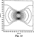
図13は、図10の型から形成される20°に傾けたキューブコーナ要素に関する再帰反射光の同一明度等高線の両極プロットである。
図14は、図10の型から形成されると共に概して直交の複数配列で配設された、20°に傾けたキューブコーナ要素に関する再帰反射光の同一明度等高線の両極プロットである。
好適な実施形態の詳細な説明
本出願に開示したキューブコーナ再帰反射性シートは、シートの主要面に対して垂直の軸を中心とするシートの全回転方向付けにおいて、相対的に大きな照射角で入射する光の相当の割合を送り返す能力を有する。再帰反射性シートは、対向キューブコーナ要素対の第1の配列と、対向キューブコーナ要素対の第2の配列とを備える。配列内のキューブコーナ要素群の対称軸は、基部面に垂直な軸線から約12°〜約30°の角度で後ろ向きに傾けられる。第1の配列のキューブコーナ要素群は第2の配列にほぼ直角に方向付けされる。
また再帰反射性物品も、すなわち40°までの、より好ましくは50°または60°までの照射角について著しく有用な全光再帰性能を全方向付け角で維持する好ましくは再帰反射性シートも開示される。構造化されたシート表面は、上記の光学的目的を達成するために好ましくは2つの直角軸に沿ってタイル張りされた2つの領域のキューブコーナ要素配列を必要とするだけであり、これによってこのようなシートの拡大生産に必要とされる努力と出費が著しく低減される。各領域は光学的に対向するキューブコーナ再帰反射性要素の配列を含み、この配列内で、シートの基部面に垂直な軸線から後方または負の方向に約12°〜約30°、より好ましくは約14°〜約20°の角度で、光学軸は斜めにされるかまたは傾けられる。
本発明の好適な実施形態を説明する場合、特定の用語が明確さのために使用される。しかし、本発明はそのように選択された特定の用語に限定されない。そのように選択された用語が、同様に機能するすべての技術的等価物を含むと理解すべきである。さらに、本出願はキューブコーナ要素形状の複数の実施形態を開示する一方、完全な立方体および切頭の立方体のような多種多様なキューブコーナ形状も使用できる。配列内の隣接した切頭キューブコーナ要素の基部縁部は典型的に同一平面である。配列内の隣接した完全キューブコーナ要素の基部縁部すべてが同一平面にあるとは限らない。当業者は、斜めの度合いの変更およびキューブ寸法の変更を本発明の開示の範囲内で行うことができることを理解するであろう。ほぼ同一の光学的結果を生み出すために計算されるキューブ形状の小さな変更も本出願の範囲内で考慮されるべきである。
再帰反射性要素の対向する対は、必ずしも同一ではないが対向する再帰反射パターンを形成する2つのキューブコーナ要素を指す。キューブコーナ要素は互いに必ずしも物理的に隣接していない。対向する対は、再帰反射性物品上で物理的に分離することが可能である。概して対偶対は、ほぼ同一であるが互いに関して180°回転された要素のような、鏡像の再帰反射パターンを形成するキューブコーナ要素の対向する対を指す。対偶対は互いに典型的に物理的に隣接している。
第1の領域のキューブコーナの配列が、約75°〜約105°、より好ましくは約85°〜約95°、より好ましくは90°、第2の面のキューブコーナの列に対して方向付けされるように、シートの構造化された表面にタイルを張ることによって、シートは、70°までの照射角について全方向付け角度で認識できる全光再帰(TLR)を維持する。360°の範囲の方向付け角度を中心とする略均一な全光再帰は、約40°、より好ましくは約50°まで、最も好ましくは約60°の照射角で、約5%の最小全光再帰、より好ましくは約10%の最小を指す。さらに、キューブコーナ要素の光学軸が好適な角度範囲内斜めにされるそのキューブコーナ要素によって構造化表面が構成される場合、シートは、相対的に大きな照射角でも、360°の方向付け角度範囲にわたって相対的に小さな理論的な全光再帰の変化を示す。かくして、大きな照射角で高水準のTLRを維持しつつ、シートは既存の再帰反射性シートよりも方向付けに対して感度は低い。概して直交した2つの領域内にキューブコーナ要素を配設するために、種々の方法が利用可能である。
本出願と同一日付に出願された関連米国特許出願は以下のものを含む:キューブコーナシート型とその製造方法(代理人整理番号第51946USA9A号);再帰反射性キューブコーナシート型およびそれによって形成されるシート(代理人整理番号第53305USA5A号);再帰反射性キューブコーナシート型およびその製造方法(代理人整理番号第53318USA8A号);再帰反射性キューブコーナシート型およびその製造方法(代理人整理番号第51952USA6A号);二重方向付けの再帰反射性シート(代理人整理番号第52303USA8B号)。
図1Aは、好適な再帰反射性シート20の構造化表面の一部の拡大図である。構造化表面は、急な斜面のキューブコーナ要素22の2つの概して直交の配列を備える複数の交互の領域26、28を含む。以下に説明するように完全なキューブコーナ要素も使用することができるが、図1Aに示したキューブコーナ要素22は一般に当業者では切頭キューブコーナ要素と呼ばれる。図示したように、キューブコーナ要素22は、光学的に対向する対偶対としてシートの一方の側の領域26、28に配設される。各キューブコーナ要素22は、3つの露光した平坦面24を有する三面体プリズムの形状を有する。キューブコーナ要素面24の間の二面角は、配列内の各キューブコーナ要素について典型的に同じであり、また約90°である。しかし、Appledorn等への米国特許第4,775,219号に示されているように、上記角度は90°からわずかに逸脱することができる。
シート20の構造化表面はキューブコーナ配列の26、28が約90度方向付け配設した複数の交互の領域を備える。好ましくは、シート20は、第1の方向付けで配設されたキューブコーナ要素22の配列を含む第1の領域26と、第2の方向付けで配設されたキューブコーナ要素の第2の領域28とを繰り返しパターンで含む。再帰反射性シートにストリップタイル張りするための適切な方法が、名称「二重方向付け再帰反射性シート」の米国特許通し番号第08/587,719号(Nestegard等)に開示されている。代わりに、シート20は、第2の領域28に略直角の第1の領域26を設ける多種多様なタイル張り構成によって形成することができる。好ましくは、変形またはさもなければ光学的に機能しないキューブコーナ要素の数が、タイル張り構成によって最少にされる。第1の領域26は、相互に交差する3組の条溝によって形成されたキューブコーナ要素22の配列を含むが、再帰反射性キューブコーナシート成形とその製造方法(代理人整理番号第51952USA6A号)に開示されているように、キューブコーナ要素を2つの条溝の組によって形成することができる。
配列内の個々のキューブコーナ要素22は、72.6°、72.60°および34.80°の基部三角形の開先角度を規定する。さらに、キューブコーナ要素は約10ミクロン〜約1000ミクロンの高さを有する。第2の領域28はシートの長手方向に沿って第1の領域26にほぼ平行に延在し、また第1の領域26に配設された配列とほぼ同一のキューブコーナ要素22の配列を含むが、第2の領域の配列は第1の領域26の配列に関して約90°の方向付けで配設される。
図1Bに最もよく示されているように、対向するキューブコーナ要素22の対称軸50は、シートの基部面54に垂直な軸線52から約12°〜約30°、より好ましくは約14°〜約20°の角度で、後方または負の方向に斜めにされるか、または傾けられる。斜めの度合いによって、入射角性の1つの主要面を有するキューブコーナ要素が提供される。軸は、米国特許第5,565,151号(Nilsen)に述べられているように、一般に当業者で「後方」または「負」の方向と呼ばれる方向に斜めにされる。これは、米国特許第4,588,258号(Hoopman)に開示されているような「前方」または「正」の方向に斜めにする方法とは区別すべきである。
後方に斜めにしたキューブコーナ要素は、キューブコーナ要素基部三角形の1つのみの開先角度が60°よりも小さいと特徴づけることもできる。他の2つの開先角度は少なくとも60°である。それに反して、前方に斜めにしたキューブコーナ要素は、基部三角形の2つの開先角度が60°よりも小さく、また単一の基部三角形の開先角度が60°よりも大きいと特徴づけることができる。ここに説明した特定の形状が好適な実施形態に関することが理解される。当業者は、斜めの度合いの変更およびキューブ寸法の変更を本発明の開示の範囲内で行うことができることを理解するであろう。
シート20は、約7x10⁸パスカルよりも小さい弾性率を有する光伝達可能な材料から形成された光伝達可能な重合体材料を含む別の本体層56を含むことができる。次に、キューブコーナ要素22は約16x108パスカルよりも大きな弾性率を有する異なった光伝達可能な材料から形成することができる。キューブコーナ要素22は好ましくは熱可塑性または熱硬化性の重合体から構成される。重合体の本体層56は好ましくは熱形成可能な重合体から構成される。本体層は、イオノマーエチレン重合体、可塑性にしたビニールハロゲン化物重合体、酸基のエチレン共重合体、脂肪族のポリウレタン、芳香族のポリウレタン、他の光透過のエラストマ、およびそれらの組合せから成る群から選択することができる。キューブコーナ要素22は単官能基、二重官能基および多官能基のアクリル酸塩またはその組合せから成る群から選択することができる。鏡面反射体は、再帰反射性シート20の全面にまたはその所定の領域に沿って取り付けることができる。
図2は、図1Aの再帰反射性シートの領域26に例示したような切頭のキューブコーナ要素の配列の全光再帰特性を示した同一明度等高線である。1.59の屈折率を有する材料から形成された切頭のキューブコーナ要素は、17°後ろ向きに斜めにされた。第1の領域26の急な斜面のキューブコーナ要素22は入射角性の1つの主要面を設ける。
本出願で用いられているように、同一明度等高線はキューブコーナ要素から得られる全光再帰をプロットする。同心の同一明度曲線は、予測される全光再帰を、種々の組合せの照射角と方向付け角度でキューブコーナ要素の基部面に入射する光の割合として表している。プロットの中心からの径方向の動きが、増加する照射角を表す一方、周囲の動きは光源に関してのキューブコーナ要素の方向付けの変化を表す。最大の再反射はグラフ上の中央点によって表され、また全光再帰で測定した最大値に関して5%の再反射低減を表す同心の同一明度等高線がプロットされている。
図3は、後ろ向きに17°斜めにし、図1に示した実施形態に従ってタイル張りし、また1.59の屈折率を有する材料から形成された切頭のキューブコーナ要素22を備えた構造化表面を有する再帰反射性シート20の全光再帰特性を示す同一明度等高線である。
表1は、このような再帰反射性シートについて図3にグラフで示したデータを含む。表1の回転方向付けデータは、パターンが90°毎に繰り返すので、完全な360°よりもむしろ0〜90°に限定される。表1の全光再帰データは、シール、反射コーティング等による損失を含まない。表1のゼロ度方向付けは正のy軸58に対応する。

開示された実施形態では、キューブコーナ要素80aと80bの形状と寸法はほぼ同一であるが、互いに関して180°方向付けして配設される。キューブコーナ要素80aは相互に垂直の3つの光学面を有する:2つの光学面は面62と66によって形成され、第3の光学面86は第3の条溝46の1つの面に対応している。面62、66、86の底部縁部は開先角度β1、β2、β3を有する基部三角形を規定する。光学面62、66、86はキューブコーナ要素頂点88で相互交差する。代わりに、面62、66、86は必ずしも頂点で交差する必要はない。むしろ、再帰反射性シートを通して光の伝達を許容するプラトまたは平坦領域を形成することができる。キューブコーナ要素80bは相互に垂直の3つの光学面:表面68と72によって形成される2つの光学面と:第3の条溝46の対向側に対応する第3の光学面82とを有する。面68、72、82の底部縁部は、開先角度β1、β2、β3を有する基部三角形を規定する。光学面68、72、82はキューブコーナ要素頂点84で相互交差する。
ここに説明した実施形態では、基部角度β1は33.06°であり、基部角度β2は73.47°であり、また基部角度β3は73.47°である。等辺でない基部三角形を有するキューブコーナ要素は、一般に当業者では「斜めにした」キューブコーナ要素と呼ばれる。後方または前方にキューブコーナ要素を斜めにすることによって、入射角性が強化される。後方の方向にキューブコーナを斜めにすることによって、光学面62、66が伸長され、また基部角度β1が低減される。さらに、後方の方向にキューブコーナ要素80を斜めにすることによって、特に約12°よりも大きく斜めにするために、共通の縁部64と70にほぼ平行の面におけるキューブコーナ要素80の入射角性の性能が改良される。以下に説明するように、キューブコーナ要素80の光学的により実働的な部分は、選択された薄層に沿って概して集中される。この特性は、大きな照射角でシート上に入射する光を再帰反射するように設計された再帰反射性シート用途に有用である。代わりに、基部角度β1、β2、β3は、国際特許96/42024(Smith等)に開示されているように、すべて異なることが可能である(不等辺三角形)。さらに、入射角性の最善の面は国際特許96/42025(Smith等)に開示されているように、必ずしも斜面の方向にはない。
キューブコーナ要素は、約0°〜約45°までの照射角でキューブコーナ要素の光学的により実働的な部分89を例示するために陰影が付けられている。キューブコーナ要素(キューブコーナ要素セグメント)の光学的により実働的な部分89は第3の条溝46に隣接して集中され、一方キューブコーナ要素の光学的により非実働的な91は第3の条溝46から変位される。相互に垂直の3つの光学面を有する単一薄層上のキューブコーナ要素の部分は、キューブコーナ要素セグメントと呼ばれる。典型的に取り外されるキューブコーナ要素の部分は、相互に垂直の3つの光学面を持たず、したがってキューブコーナ要素セグメントではない。光学的により実働的なキューブコーナ要素セグメントの密度は、光学的性質を強化するために高くされる。
光学的により実働的な部分89は、角度β2、β3の近くに配置された光学的により非実働的な領域87を含むことができる。図4に示したキューブコーナ要素80a、80bの相対的に小さな部分は、光学的に実働的である。照射角がゼロに向かって減るにつれ、光学的により実働的な部分89の面積およびその領域の有効開口が減少する。ある点で、有効開口は隙間になり、主にキューブコーナ要素の光学軸を収容する面内の再帰反射性物品を離れる光を隙間に垂直に回折させる。隙間開口内の回折は主に1つの面の反射光を導き、ASTM E808−94に述べられているように、再帰反射光の発散特性の均一性を悪化させる。
図5は、複数の薄層(90cと90f)を図4に示した組立体から取り除くことによって形成される複数の光学的に対向するキューブコーナ要素セグメントの平面図を示している。薄層すべての厚さは同一であってもよいし、同一でなくてもよい。代替実施形態では、薄層90c、90fは隣接した薄層の1つ、例えば90bと90eにそれぞれ近接することができる。次に、90cと90fに対応するこのような近接した薄層の部分は、機械加工によって取り除くことができる。
1つの好適な実施形態では、図5に示した複数のキューブコーナ要素セグメントは、それらのそれぞれの動作面上に配設されたキューブコーナ要素セグメントの光学的により非実働的な部分を有するそれらの薄層を組立体から取り除くことによって得られる。組立体90c、90fから取り除かれた薄層は、本出願では犠牲的薄層と呼ぶ。犠牲的薄層は組立体から取り外され、また残りの薄層は適切な取付け具で再び組み立てられて、複数のキューブコーナ要素セグメントを備える構造化表面を提供し、前記要素セグメントは、元の組立体の複数の薄層の動作面に形成された完全成形のキューブコーナ要素の光学的により実働的な部分に一致する。キューブコーナ要素セグメントの光学的により非実働的な部分は取り除かれるので、この型の複製として形成される再帰反射体は、広範囲の照射角にわたって元の組立体の表面の複製として形成される再帰反射体よりもはるかに高い再帰反射効率を示すことができる。薄層90c、90fは第3の条溝組46を形成する前に組立体から選択的に取り除くことができる。図5の型からの再帰反射性シートの形成について以下に説明する。
図4と図5の光学的に実働的な部分89は複数のキューブコーナ要素の対偶対を例示している。薄層90は種々の構造で配設できることが理解されよう。例えば、薄層90b、90e、90hは第1の副配列内に一緒にまとめることができ、また薄層90a、90d、90gは第1の副配列から物理的に分離して第2の副配列内に一緒にまとめることができる。薄層90b、90e、90h上のキューブコーナ要素は、物理的に隣接することなく、キューブコーナ要素90a、90d、90gに光学的に対向することができる。上述のように構成される再帰反射性シートは好ましくは4つの副配列を含むことが好ましい。
図6は、1.59の屈折率を有する材料から形成され、後ろ向きに18°で斜めにした図4と図5によるキューブコーナ要素を備えた構造化表面を有する再帰反射性シートの全光再帰特性を示す同一明度等高線である。再び、急な斜面の好適なキューブコーナ要素によって、入射角性の1つの主要面が設けられる。
図7は、後ろ向きに18°斜めにし、図1に示した実施形態に従ってタイル張りし、また1.59の屈折率を有する材料から形成された図5のキューブコーナ要素セグメントを備えた構造化表面を有する再帰反射性シートの全光再帰特性を示す同一明度等高線である。
以下の表2は、表1と同じフォーマットで作成され、図7のグラフで示したデータを含む。表2の回転方向付けデータは、パターンが90°毎に繰り返すので、完全な360°よりもむしろ0〜90°に限定される。表2の全光再帰データは、シール、反射コーティング等による損失を含まない。表2のゼロ度方向付けは正のy軸58に対応する。
説明目的のために、デカルト座標系を薄層100に重ね合わせることができる。第1の基準面124は第1の主要面112と第2の主要面114の間でセンタリングされる。x−z面と呼ぶ第1の基準面124はその法線ベクトルとしてy軸を有する。x−y面と呼ぶ第2の基準面126は、薄層100の動作面とほぼ同一平面に延在し、またその法線ベクトルとしてz軸を有する。y−z面と呼ぶ第3の基準面128は、第1の端面120と第2の端面122との間でセンタリングされ、またその法線ベクトルとしてx軸を有する。好適な実施形態の幾何的な特性は、ここに説明したデカルト基準面以外の座標系を用いて、あるいは薄層の構造を参考にして説明できることが理解される。
薄層100は、図示した角度δ1で配設された平行に隣接した複数のV字形状の条溝130を備える第1の条溝の組を収容する。少なくとも2つの隣接した条溝130は薄層100の中に形成され、各条溝は、条溝頂点133で交差する第1と第2の条溝面132、134を有する。薄層の縁部で、条溝形成操作によって単一の条溝面132を形成することができる。隣接した条溝の条溝面132と134が基準縁部136に沿ってほぼ直交して交差することが重要である。好ましくは、このパターンは複数の薄層100の動作面全体にわたって繰り返される。
条溝130は、フライス削り、ルーリング、溝切りおよびフライカッティングのような精密加工技術を含む任意の種々の適切な材料除去技術を用いて、複数の薄層の動作面の部分を取り除くことによって形成される。さらに、化学エッチングまたはレーザ除去技術もまた使用することができる。1つの実施形態では、第1の条溝の組の条溝130は高精密加工作業によって形成され、この作業では、90°の開先角度を有するダイヤモンド切削工具は、基部面180にほぼ平行である軸に沿って複数の薄層100の動作面に交差して、繰り返し横断運動される。切削工具は、工具が複数の薄層100に交差して変動する深さで切削するように、基部面180に平行でない軸に沿って交互に運動させることができる。複数の薄層を運動させる一方で、加工工具を静止保持できることが理解される;複数の薄層100と加工工具との間の相対運動を有する任意の技術が意図される。かくして、平面図では、基準縁部136は、複数の薄層100のそれぞれの第1の基準面124に対して垂直に現れる。
平行の隣接した複数のV字形状の条溝138を備える第2の条溝の組は、複数の薄層100の動作面に形成され、薄層は角度δ2で配設される。少なくとも2つの隣接した条溝138は複数の薄層100の動作面に形成され、各条溝138は、条溝頂点141で交差する第3と第4の条溝面140、142を有する。薄層の縁部で、条溝形成操作によって単一の条溝面140を形成することができる。隣接した条溝の条溝面140と142は基準縁部144に沿ってほぼ直交して交差することが重要である。好ましくは、このパターンは複数の薄層100の動作面全体にわたって繰り返される。
好ましくは、条溝138は、第1の条溝の組の条溝130と同一の深さで複数の薄層100の動作面に形成される。さらに、第2の条溝の組の条溝138は、条溝頂点141と基準縁部144が第1の条溝の組の条溝130のそれぞれの条溝頂点133と基準縁部136とほぼ同一平面であるように形成されることが好ましい。
好ましくは各薄層100に少なくとも1つの条溝146を含む第3の条溝の組が形成される。第3の条溝146は、第1の基準面124に平行にある軸に沿ってそれぞれの条溝頂点152で交差する第5と第6の条溝面148、150を規定する。第5の条溝面148が第1の条溝面132と第2の条溝面134にほぼ直角であるように、第3の条溝146が形成されることが重要である。第5の条溝面148の形成によって、複数のキューブコーナ要素160が造られる。
各キューブコーナ要素160は第1の条溝面132と、第2の条溝面134と、第5の条溝面148の部分によって規定され、これらはある点で相互に交差してキューブコーナの先端または頂点162を規定する。同様に、第6の条溝面150は第3の条溝面140と第2の条溝面142とにほぼ直角である。6番目の条溝表面150の形成が薄層100の動作面の中また複数のキューブコーナ要素170をもたらす。各キューブコーナ要素170は第3の条溝面140と、第4の条溝面142と、第6の条溝面150の部分によって規定され、これらはある点で相互に交差してキューブコーナの先端または頂点172を規定する。好ましくは、第5の条溝面148と第6の条溝面150の両方は薄層100の動作面の複数のキューブコーナ要素を形成する。しかし、第5の条溝面148または第6の条溝面150のみによってキューブコーナ要素が形成されるように、第3の条溝146を交互に形成することができる。さらに、頂点162、172は必要ではなくなる。ある用途では、平坦な領域をキューブコーナ要素の中に形成してシート内の光伝達を可能にすることができる。
好ましくは、条溝146も高精密加工作業によって形成される。開示された実施形態では、約46.55°(約12°の傾きに対応)〜約10.52°(約30°の傾きに対応)、より好ましくは約42.52°(約14°の傾きに対応)〜約30.52°(約20°の傾きに対応)の半開先角度を有するダイヤモンド切削工具は、ほぼ第1の基準面124によって収容されると共に基部面180に平行である軸に沿って各薄層100の動作面に交差して移動する。急な斜面のキューブコーナ要素を達成するために、条溝146は、第1と第2の条溝の組130、138の条溝の頂点133、141よりもそれぞれ深い。
薄層100の動作面に形成されたキューブコーナ要素の形状は、形状が100%に近い最大有効開口を示すので、「完全」または「高効率」キューブコーナ要素形状として特徴づけることができる。かくして、動作面の複製として形成される再帰反射体は、ほぼキューブコーナ要素の対称軸に沿って再帰反射体に入射する光に応答して高い光学効率を示す。さらに、キューブコーナ要素160と170は対向方向付けで配設され、また第1の基準面124に関して対称であり、また大きな照射角で再帰反射体に入射する光に応答して対称な再帰反射性性能を示す。しかし、キューブコーナ要素が基準面を中心に対称である必要はない。
好適な薄層100は、機械加工可能なプラスチック(例えばポリエチレンテレフタル酸塩、ポリメタクリル酸メチルおよびポリカーボネート)または金属(例えば黄銅、ニッケル、銅またはアルミニウム)のような、精度公差を保持する能力のある寸法的に安定した材料から形成される。薄層の物理的寸法は主として加工上の制限によって制約される。好ましくは薄層の厚さは少なくとも0.1mmであり、高さは5.0〜100.0mmの間にあり、また幅は10〜500mmの間にある。しかし、これらの寸法は例示目的のために設けられ、また限定することを意図するものではない。主要面112、114の間の平坦な界面は、負の複写の品質の悪化をもたらすと思われる隣接した薄層の間の間隔を最小にするために、またはみ出しが薄層の間の間隔内に移動するのを最小にするために、加工段階の間は隣接した薄層の間に維持され、また位置合わせの問題と薄層の取扱いによる損傷とを最小にするべく、加工段階で形成される引き続く型内に維持される。
再帰反射性シートのような再帰反射性物品の製造では、複数の薄層の構造化表面は、電気鋳造技術または他の従来の複製技術を用いて複製することができるマスター型として使用される。複数の薄層はほぼ同一のキューブコーナ要素を含むことができるか、または種々の寸法、形状または方向付けのキューブコーナ要素を含むことができる。当業者で「スタンパ」と呼ばれる複製の構造化表面は、キューブコーナ要素の負の像を含んでいる。この複製は、再帰反射体を形成するための型として使用することができる。しかし、より一般的には、多数の正または負の複製を組み立て、再帰反射性シートの形成に有用な十分に大きな型が形成される。このような再帰反射性シートは、例えば上述のようなキューブコーナ要素の配列によって予備成形したシートを打ち出すことによって、または流体材料を型内に鋳込むことによって、一体材料として製造することができる。日本国特許8−309851と米国特許第4,601,861号(Pricone)参照。代わりに、再帰反射性シートは、PCT出願国際特許第95/11464および米国特許第3,648,348号に教示されているように、キューブコーナ要素を予備成形されたフィルムに対して鋳造することによって、あるいは予備成形したフィルムを予備成形したキューブコーナ要素に張り合わせることによって、層状製品として製造することができる。実例によって、マスター型の上にニッケルを電着して形成されるニッケル鋳型を用いて、本発明の有効なシートを造ることができる。電気鋳造鋳型は、約1.59の屈折率を有する約500μmの厚さのポリカーボネートフィルム上に鋳型のパターンをエンボス加工するためのスタンパとして使用することができる。鋳型はプレス内で使用することができ、プレスは約175〜200℃の温度で実行される。
本発明による反射性シートを造るために有用な材料は、寸法的に安定し、耐久性であり、耐候性であり、また所望の構造に容易に成形可能な材料である。適切な材料の実例は、Rohm and Haasのプレキシグラス樹指;約1.6の屈折率を有する好ましくは放射加硫された熱硬化性のアクリル酸塩とエポキシアクリル酸塩、ポリカーボネート;(名称「SURLYN」で市販されている)ポリエチレンベースのイオノマー;ポリエステル;セルロースアセテートブチレートのような、概して約1.5の屈折率を有するアクリルを含む。概して、典型的に熱と圧力の下で成形可能な光学的に透過の材料を使用することができる。他の適切な材料がSmith等への米国特許第5,450,235号に開示されている。必要に応じて、シートは着色剤、染料、紫外線吸収剤または他の添加剤を含むことができる。
ある状況では再帰反射性シートに補強層を設けることが望ましい。特に、補強層は全内部反射の原理に従って光を反射する再帰反射性シートに有用である。適切な補強層は、再帰反射性シートに効率的に係合できる着色材料を含む任意の透明または不透明の材料から造ることができる。適切な補強材料は、アルミニウムシート、亜鉛めっき鋼、ポリメタクリル酸メチルのような重合体材料、ポリエステル、ポリアミド、ポリフッ化ビニル、ポリカーボネート、ポリ塩化ビニル、ポリウレタン、およびこれらおよび他の材料から造られる多種多様な薄層を含む。
補強層またはシートは、格子パターンまたは反射要素に適切な他の任意の構造でシールすることができる。シールは、超音波溶接、接着剤を含むいくつかの方法によって、または反射要素の配列上の別個の位置のヒートシール(例えば米国特許第3,924,928号参照)によって行うことができる。シールは、汚れおよび/または水分のような汚染物質の進入を阻止し、またキューブコーナ要素の反射面に隣接して空隙を維持するために望ましい。
複合体に追加の強度または強靭さが必要とされるならば、ポリカーボネート、ポリブチレートまたは強化プラスチックの補強シートを使用することができる。得られる再帰反射性材料の可撓性の程度に応じて、材料を細片または他の適切な構造体の中に転造または組み込むことができる。また再帰反射性材料は、接着剤を塗布するかまたは他の固定手段を用いる追加段階なしに、任意の基板に利用するために前記再帰反射性材料を有用にする接着剤および解放シートで補強することもできる。
キューブコーナ要素は、米国特許第4,775,219号によって教示されているように、物品によって再帰反射される光を所望のパターンまたは発散形態に分布させるように、個々に適応させることができる。典型的に、導入される条溝の半角誤差は±20円弧分よりも小さく、また±5円弧分よりも小さいことがしばしばである。
図11は、1.59の屈折率を有する材料から形成され、後ろ向きに14°斜めにした(条溝146は42.52°の開先角度を有する)図8−10による完全なキューブコーナ要素を備えた構造化表面を有する再帰反射性シートの全光再帰特性を示す同一明度等高線である。図8−10の急な斜面の完全なキューブコーナ要素によって、入射角性の1つの主要面が設けられる。
図12は、後ろ向きに14°斜めにし、図1の実施形態に従ってタイル張りし、また1.59の屈折率を有する材料から形成された図8−10の完全なキューブコーナ要素を備えた構造化表面を有する再帰反射性シートの全光再帰特性を示す同一明度等高線である。表3は図12にグラフで示した全光再帰データを含む。表3の回転方向付けデータは、パターンが90°毎に繰り返すので、完全な360°よりもむしろ0〜90°に限定される。
表3の全光再帰データは、シール、反射コーティング等による損失を含まない。表3のゼロ度方向付けは正のy軸58に対応する。
参照したすべての特許および特許出願は、発明の背景に開示されたそれらを含み、参考として本出願に組み込まれている。本発明について、その複数の実施形態を参考にして説明してきた。当業者には、本発明の範囲から逸脱することなしに、説明した実施形態について多くの変更を行うことができることが明白であろう。したがって、本発明の範囲は説明した好適な構造と方法とに限定されるべきでなく、むしろ以下の請求項の広範な範囲によって限定されるべきである。Field of Invention
The present invention generally provides a cube corner retroreflection having the ability to send back a significant percentage of light incident at a relatively large illumination angle, regardless of the rotational orientation of the sheet about an axis perpendicular to the major surface of the sheet. Related to sex sheets.
Background of the Invention
Retroreflective materials are characterized by redirecting incident light back toward the light source. This property has led to the widespread use of retroreflective sheets in a variety of eye-catching applications. Retroreflective sheets are used on flat and rigid articles such as road signs and barricades, for example, in poor lighting conditions to make them more noticeable. Retroreflective sheets are also used for irregular or flexible surfaces. For example, a retroreflective sheet can be glued to the side of a cargo trailer that requires a sheet to cover corrugations and protruding rivets, or the sheet can be a road worker's safety vest or other such It can be glued to a flexible body part such as a safety garment.
Many eye-catching applications depend on specific performance standards for retroreflective sheets. Manufacturers must show that their retroreflective sheets have the ability to meet relevant performance standards in order to be considered as market suppliers. There is a standard body for both the retroreflective description (see ASTM instruction E808-93b, standard test for retroreflective description) and the measurement of retroreflectors. (See ASTM instruction E809-94a, standard test for measuring photometric properties of retroreflectors).
Two known types of retroreflective sheets are microsphere-based sheets and cube corner sheets. Microsphere-based sheets (sometimes referred to as “beaded” sheets) are typically at least partially embedded in a tie layer and associated specular or scattering reflective materials (eg, pigment particles) to retroreflect incident light. A group of microspheres having a metal flake or vapor deposition coating). Illustrative examples are disclosed in US Pat. Nos. 3,190,178 (McKenzie), 4,025,159 (McGrath), and 5,066,098 (Kult). Due to the symmetry of the beaded retroreflector, the microsphere-based sheet exhibits a relatively uniform angle of incidence when rotated about an axis perpendicular to the sheet surface. Therefore, the retroreflective performance of the beaded sheet is relatively less affected by the orientation of the sheet on the surface of the object. In general, however, microsphere-based sheets exhibit relatively low retroreflective efficiency. A retroreflective sheet with a bead typically exhibits a total light recursion of about 5% to 15% with an observation cone at an angle of about 2 °.
A cube corner retroreflective sheet comprises a body portion that typically has a substantially flat base surface and a structured surface with a plurality of cube corner elements opposite the base surface. Each cube corner element comprises three substantially perpendicular optical surfaces that typically intersect at a single reference point or vertex. The base of the cube corner element serves as an aperture through which light is propagated into the cube corner element. In use, light incident on the base surface of the sheet is refracted at the base surface of the sheet, propagates through each base of cube corner elements disposed on the sheet, and is reflected from each of the three vertical cube corner optical surfaces; It is guided again toward the light source.
One aspect of many performance standards requires a retroreflective sheet to send back a specific percentage of light incident on the sheet surface at various illumination angles. The total light retroreflective property of a retroreflective sheet as a function of the illumination angle of incident light is generally referred to by those skilled in the art as the “incidence angle” of the sheet. Is a retroreflective sheet capable of sending back a significant percentage of light incident at a relatively large illumination angle, as strong as disclosed in the same brightness curve of US Pat. No. 4,588,258 (Hoopman)? Alternatively, it can be characterized as having a wide incident angle.
On the other hand, retroreflective sheets with a low incidence angle lose their retroreflective brightness rapidly as the angle of incidence deviates from 0 ° (all light recursion decreases). In addition, the angle of incidence typically varies around a range of orientation angles of about 360 ° (orientation uniformity) and requires proper alignment of the retroreflective sheet for each application. The angle of incidence and orientation uniformity of the retroreflective sheet are important performance factors, which means the driver's ability to see objects such as road signs or safety barriers in bad lighting conditions in various directions This is because it greatly affects
The symmetry axis of the cube corner element, also called the optical axis, is the axis that forms an angle equal to the three optical surfaces of the cube corner element. Cube corner elements typically exhibit the highest optical efficiency in response to light incident on the base of the element approximately along the optical axis. As the incident angle deviates from the optical axis, the amount of light retroreflected by the cube corner retroreflector decreases.
Cube corner elements offer the advantage of being a significantly more efficient retroreflector than beads. The terms “active area” and “effective aperture” are used in cube corner technology to characterize the portion of a cube corner element that retroreflects light incident on the base of the element. Detailed teachings regarding the determination of the working aperture for cube corner element design are beyond the scope of the present disclosure. One method for determining the effective aperture of a cube corner shape is described by Eckhardt, “Applied Optics”,
The predicted total light recursion (TLR) for a cube corner versus even pair array can be calculated from knowledge of% active area and light intensity. The light intensity can be reduced by front loss and by reflection from each of the three cube corner surfaces for retroreflected light. Total light recursion is defined as the product of% active area and light intensity or as the percentage of total incident light that is retroreflected. A description of all-optical recursion for directly processed cube corner arrays is given in US Pat. No. 3,712,706 (Stamma).
The light recurrence characteristics of basic cube corner elements are inherently asymmetric in nature. Total internal reflection (TIR) depletion is the most important cause of this asymmetry in non-metallized cube corner retroreflectors. By applying the reflecting surface with a specular reflector, the asymmetry of the reflecting pattern is considerably reduced. However, metallized cube corner arrays are typically not white enough for daytime observations, such as labeling applications. The durability of the reflective vapor deposition coating may also be insufficient. Finally, the asymmetric part is due in part to the asymmetric physical shape of the cube corner elements. See Rityan, Corner Cube Reflector Optics, Soviet Journal of Optics Technology, 34, 195 (1967).
Retroreflective sheets formed from cube corner elements exhibit a corresponding asymmetry in their light retroreflective properties. By way of example, U.S. Pat. No. 3,712,706 to Stamm ("the '706 patent") discloses the optical recurrence characteristics of the three lobes of a single cube corner element. Similarly, U.S. Pat. No. 4,600 (Burke) and No. 4,243,618 (Van Arnam) show that the total light recursion retroreflected by a cube corner retroreflective sheet is the illumination angle of the incident light and the orientation angle of the sheet on the substrate. An array of cube corner elements having a plurality of regions with different angular orientations is disclosed as varying as a function of Burke and Van Arnam's six lobe optical recursion characteristics It is a characteristic.
One way to reduce the asymmetry of the retroreflective sheeting is done by providing the retroreflective sheeting structure with a plurality of separate cube corner arrays arranged in different orientations; "Technology called." The Burke and Van Arnam patents disclose a retroreflective sheet having an array of conventional truncated cube corner elements having equilateral base triangles tiled in various different orientations on the surface of the sheet. Although the structures suggested in these references deal with asymmetry problems, the cube corner shapes disclosed in these references only allow a small part of the cube to function optically in a specific orientation. Suffers a rapid drop in all-light recursion at an illumination angle greater than about 40 °. Thus, the retroreflective sheets according to these references do not provide sufficient all-light recursion at large illumination angles for many applications.
Another way to accept this change in incidence angle is to design the retroreflective sheet to have a specific surface with improved incidence angle. By way of illustration, the Hoopman patent discloses a retroreflective sheet in which cube corner elements are disposed in the opposing pair of pairs, with the respective symmetry axes of the pair of pairs tilted toward each other. This shape allows retroreflectivity with improved incidence angle in a plane substantially coincident with the plane containing the symmetry axis of the cube corner element, which is also identified as the X-axis plane and also in the Y-axis plane perpendicular to the X-axis plane. A sheet is obtained. In use, the sheet is preferentially oriented on the substrate such that the above surface coincides with the surface on which light is incident on the sheet. By way of illustration, the preferred orientation of the sheet on the road sign is to have the X-axis plane paired almost parallel to the ground.
US Pat. No. 5,565,151 (Nilsen) discloses a pair of retroreflective cube corner elements that are tilted or slanted in the negative direction between greater than 1.0 ° and less than about 7.0 °. is doing. The portion of one cube corner element of the even pair is removed, creating a smaller element that increases the viewing angle performance.
US Patent Application Serial No. 08 / 5887,719 (Nestgard et al.), Entitled “Double Oriented Retroreflective Sheet”, is a cube corner oriented so that their major surfaces of incidence angle are substantially perpendicular to each other. A retroreflective sheet having alternating regions of arrangement is disclosed.
Thus, there is a need in the art for a retroreflective sheet that maintains an all-light recursion that is clearly useful over a 360 ° orientation angle range, particularly with illumination angles greater than about 40 °. Furthermore, there is a need in the art for a retroreflective sheet having a relatively small change in total light recursion over a 360 ° orientation angle range with larger illumination angles, particularly greater than about 40 °.
Disclosure of the invention
The preferred cube corner retroreflective sheet disclosed in this application is an all-optical recursion where the sheet is clearly useful at all orientation angles for illumination angles of about 40 °, more preferably about 50 °, and most preferably about 60 °. To maintain steep beveled cube corner elements that are tiled in approximately two vertical orientations. Thus, a cube corner retroreflective sheet is disclosed that is relatively insensitive to orientation when compared to existing cube corner retroreflective sheet structures. A suitable retroreflective sheet maintains a clear all useful light reflex performance at large illumination angles while maintaining high all light recursion at lower illumination angles.
The retroreflective article comprises a substrate having a base surface and a structured surface comprising a plurality of arrays of cube corner elements opposite the base surface. The array of cube corner elements comprises a first array of opposing cube corner element pairs and a second array of opposing cube corner element pairs. The symmetry axis of the cube corner elements in the first array is tilted backwards at an angle of about 12 ° to about 30 ° from an axis perpendicular to the base plane. The symmetry axis of the cube corner elements in the second array is also tilted backwards by an angle of about 12 ° to about 30 ° from an axis perpendicular to the base plane. The second array of cube corner elements is approximately in the first array such that the retroreflective article performs a minimum total light recursion of about 5% over an orientation angle range of about 360 ° at an illumination angle of about 40 °. Oriented vertically.
In an alternative embodiment, the symmetry axis of the cube corner elements in the first array is tilted backwards at an angle of about 12 ° to about 30 ° from an axis perpendicular to the base surface. The symmetry axis of the cube corner elements in the second array is also tilted backwards by an angle of about 12 ° to about 30 ° from an axis perpendicular to the base plane. The second array of cube corner elements is oriented substantially perpendicular to the first array such that the retroreflective article performs a substantially uniform all-light recursion around a 360 ° orientation angle range. In other embodiments, the cube corner elements in the first and second arrays are tilted backwards at an angle of about 15.1 ° to about 30 °.
The first array and the second array occupy approximately equal portions of the structured surface of the retroreflective article. The cube corner element is a substantially trihedral structure including three mutually perpendicular triangular optical surfaces intersecting at a vertex and a triangular base. The triangular base of the truncated cube corner element is substantially flush with the base surface of the article. Instead, the cube corner element comprises a “perfect cube”, for example, three mutually perpendicular optical surfaces including two rectangular optical surfaces and a third optical surface that intersect at a vertex, and a rectangular base. It can be a substantially polygonal structure.
More preferably, the axis of symmetry of the cube corner elements in the array is tilted back at an angle of about 14 ° to about 20 ° from an axis perpendicular to the base plane. The symmetry axes of the cube corner elements in the first and second arrangements can be tilted the same amount or different amounts. The second array is preferably oriented at an angle of about 85 ° to about 95 °, and most preferably about 90 ° with respect to the first array.
The retroreflective article exhibits a maximum theoretical total light recursion of about 100% in response to light incident on the article along an axis perpendicular to the base surface of the article. The retroreflective article is at an illumination angle of about 40 °, more preferably at an illumination angle of about 50 °, most preferably at an illumination angle of about 60 °, and over an orientation angle range of about 360 °, preferably about 5 °. It is preferred to have a minimum total light recursion capability of%, more preferably 10%.
Opposed pairs of cube corner elements may or may not be physically adjacent to each other and may have the same or different retroreflective patterns. In one embodiment, the opposing pairs of cube corner elements are even pairs that form mirror image retroreflective patterns, such as elements that are substantially identical but rotated 180 ° with respect to each other. The retroreflective pattern and the reflective pattern refer to a configuration of reflected light typically exemplified as the same brightness contour.
The substrate and the cube corner element are preferably formed as a single piece from a light-transmittable material having a refractive index of 1.3 to 1.7. In one embodiment, the body layer of the retroreflective article is about 7x10. 8 A light-transmittable polymeric material having a modulus of elasticity less than Pascal, and a cube corner element of about 16 × 10 8 It is formed from a material capable of transmitting light having a larger elastic modulus than Pascal. The cube corner element incorporates a small deviation from perfect orthogonality, which can change the light distribution of the exit cone of retroreflected light.
The first and second arrays of cube corner elements can be deposited with a specular reflective material. The sealing medium can be disposed adjacent to the first and second arrays of cube corner elements. The sealing medium is preferably coupled to the structured surface by a cross-coupled network defining a plurality of cells, and the cube corner elements are hermetically sealed within the plurality of cells. The sealing medium maintains the air interface with the structured surface so that the cube corner elements are retroreflected according to the principle of total internal reflection.
Also disclosed is a method of making a retroreflective article using a suitable mold assembly and molding suitable for use in forming the retroreflective sheet. The mold assembly includes a substrate having a base surface and a molding surface opposite the base surface. The molding surface includes opposed pairs of first and second arrays of cube corner elements in approximately equal proportions. The symmetry axis of the cube corner elements in the array is preferably tilted backwards at an angle of about 15.1 ° to about 30 ° from an axis perpendicular to the base plane. The second array of cube corner elements is oriented substantially perpendicular to the first array. In an alternative embodiment, the opposing pairs of first and second arrays of cube corner elements are tilted by an angle of about 15.1 ° to about 20 °. A method for making a retroreflective article includes forming a replica of a mold. The replica of the mold includes a molding surface having a female mold image. The retroreflective article is formed on the replica molding surface.
[Brief description of the drawings]
FIG. 1A is a plan view of a portion of a retroreflective sheet according to a preferred embodiment of the present invention.
FIG. 1B is a partial side view of the structured surface of the sheet of FIG. 1 taken along line II.
FIG. 2 is a bipolar plot of identical lightness contours of retroreflected light for a single array of cube corner sheets of FIG. 1 prior to tiling.
FIG. 3 is a bipolar plot of the same brightness contours of retroreflected light for the cube corner sheet of FIG.
FIG. 4 is a plan view of a mold for forming a retroreflective sheet.
FIG. 5 is a plan view of the mold of FIG. 4 for forming a retroreflective sheet according to an embodiment of the present invention.
FIG. 6 is a bipolar plot of the same brightness contours of retroreflected light for a cube corner sheet formed from the mold of FIG.
FIG. 7 is a bipolar plot of identical brightness contours of retroreflected light for cube corner sheets formed from the mold of FIG. 5 arranged in a generally orthogonal array.
FIG. 8 is a perspective view of an alternative embodiment of a cube corner element.
FIG. 9 is a plan view of the cube corner element of FIG.
FIG. 10 is a side view of a mold for forming a retroreflective sheet using the thin layer of FIG.
FIG. 11 is a bipolar plot of the same brightness contours of retroreflected light for a cube corner element tilted at 14 ° formed from the mold of FIG.
FIG. 12 is a bipolar plot of the same brightness contours of retroreflected light for cube corner elements tilted at 14 ° formed from the mold of FIG. 10 and arranged in a generally orthogonal array.
FIG. 13 is a bipolar plot of the same brightness contours of retroreflected light for a cube corner element tilted by 20 ° formed from the mold of FIG.
14 is a bipolar plot of the same lightness contours of retroreflected light for cube corner elements tilted at 20 ° formed from the mold of FIG. 10 and arranged in a generally orthogonal array.
Detailed Description of the Preferred Embodiment
The cube-corner retroreflective sheet disclosed in this application provides a substantial proportion of light incident at a relatively large illumination angle in the full rotation orientation of the sheet about an axis perpendicular to the principal plane of the sheet. Has the ability to send back. The retroreflective sheet comprises a first array of opposing cube corner element pairs and a second array of opposing cube corner element pairs. The symmetry axis of the cube corner elements in the array is tilted backwards at an angle of about 12 ° to about 30 ° from an axis perpendicular to the base plane. The first array of cube corner elements is oriented substantially perpendicular to the second array.
Also disclosed are retroreflective articles, i.e., preferably retroreflective sheets that maintain all-light retroreflective performance at an omnidirectional angle that is significantly useful for illumination angles up to 40 °, more preferably up to 50 ° or 60 °. The The structured sheet surface only requires a two area cube corner element array, preferably tiled along two perpendicular axes, to achieve the optical objectives described above. The effort and expense required to expand the production of such sheets is significantly reduced. Each region includes an array of optically opposed cube corner retroreflective elements within which about 12 ° to about 30 °, or more preferably, backward or negative from an axis normal to the base surface of the sheet. At an angle of about 14 ° to about 20 °, the optic axis is tilted or tilted.
In describing preferred embodiments of the present invention, specific terminology is used for the sake of clarity. However, the present invention is not limited to the specific terms so selected. It is to be understood that the term so selected includes all technical equivalents that function similarly. Further, while the present application discloses multiple embodiments of cube corner element shapes, a wide variety of cube corner shapes such as full cubes and truncated cubes can also be used. The base edges of adjacent truncated cube corner elements in the array are typically coplanar. Not all base edges of adjacent full cube corner elements in the array are coplanar. Those skilled in the art will appreciate that changing the degree of skew and changing the cube dimensions can be made within the scope of the present disclosure. Small changes in cube shape calculated to produce nearly identical optical results should also be considered within the scope of this application.
Opposing pairs of retroreflective elements refer to two cube corner elements that form an opposing retroreflective pattern, although not necessarily identical. Cube corner elements are not necessarily physically adjacent to each other. Opposing pairs can be physically separated on the retroreflective article. In general, an even pair refers to an opposing pair of cube corner elements that form a mirror image of a retroreflective pattern, such as elements that are substantially identical but rotated 180 ° relative to each other. Pairs are typically physically adjacent to each other.
The orientation of the cube corners in the first region is from about 75 ° to about 105 °, more preferably from about 85 ° to about 95 °, more preferably 90 °, oriented relative to the second corner cube corner row. As is done, by tiling the structured surface of the sheet, the sheet maintains a total light recursion (TLR) that can be recognized at all orientation angles for illumination angles up to 70 °. A substantially uniform total light recursion centered around an orientation angle in the range of 360 ° is about 5% minimum total light at an illumination angle of about 40 °, more preferably up to about 50 °, most preferably about 60 °. Refers to recursion, more preferably a minimum of about 10%. Furthermore, if the structured surface is constituted by a cube corner element whose optic axis is slanted within a preferred angular range, the sheet will have a 360 ° orientation angle range even at relatively large illumination angles. A relatively small theoretical all-optical recursion change over time. Thus, the sheet is less sensitive to orientation than existing retroreflective sheets while maintaining a high level of TLR at a large illumination angle. Various methods are available for arranging cube corner elements in two generally orthogonal regions.
Related U.S. patent applications filed on the same date as this application include the following: cube corner sheet mold and method of manufacture thereof (Attorney Docket No. 51946 USA9A); retroreflective cube corner sheet mold and formed thereby Sheet (agent number 53305USA5A); retroreflective cube corner sheet type and manufacturing method thereof (agent number 53318USA8A); retroreflective cube corner sheet type and manufacturing method (agent number no. 51952 USA6A); a double-oriented retroreflective sheet (attorney docket number 52303 USA8B).
FIG. 1A is an enlarged view of a portion of the structured surface of a
The structured surface of the
The individual
As best shown in FIG. 1B, the axis of
A cube corner element that is slanted back can also be characterized as having a groove angle of only one of the cube corner element base triangles less than 60 °. The other two groove angles are at least 60 °. On the other hand, a cube corner element tilted forward may be characterized as having two groove angles of the base triangle smaller than 60 ° and a groove angle of a single base triangle larger than 60 °. it can. It will be appreciated that the specific shapes described herein relate to the preferred embodiment. Those skilled in the art will appreciate that changing the degree of skew and changing the cube dimensions can be made within the scope of the present disclosure.
FIG. 2 is an identical lightness contour showing the all-light recursive properties of an array of truncated cube corner elements as illustrated in
As used in this application, the same brightness contour plots the total light recursion obtained from the cube corner elements. Concentric identical brightness curves represent the predicted total light recursion as the percentage of light incident on the base surface of the cube corner element at various combinations of illumination and orientation angles. Radial motion from the center of the plot represents increasing illumination angles, while ambient motion represents changes in the orientation of cube corner elements with respect to the light source. The maximum re-reflection is represented by the center point on the graph, and concentric identical brightness contours are plotted representing a 5% re-reflection reduction with respect to the maximum value measured with all-light recursion.
FIG. 3 shows a structured surface with a truncated
Table 1 contains the data graphically represented in FIG. 3 for such a retroreflective sheet. The rotation orientation data in Table 1 is limited to 0-90 ° rather than full 360 ° because the pattern repeats every 90 °. The all-optical recursion data in Table 1 does not include losses due to seals, reflective coatings, and the like. The zero degree orientation in Table 1 corresponds to the positive y-
In the disclosed embodiment, the
In the embodiment described here, the base angle β 1 Is 33.06 ° and the base angle β 2 Is 73.47 ° and the base angle β Three Is 73.47 °. Cube corner elements having base triangles that are not equilateral are generally referred to by those skilled in the art as "tilted" cube corner elements. Incident angle is enhanced by tilting the cube corner elements backwards or forwards. By tilting the cube corner in the backward direction, the
The cube corner elements are shaded to illustrate an optically more
The optically more
FIG. 5 shows a plan view of a plurality of optically opposed cube corner element segments formed by removing a plurality of thin layers (90c and 90f) from the assembly shown in FIG. The thickness of all the thin layers may or may not be the same. In an alternative embodiment, the
In one preferred embodiment, the plurality of cube corner element segments shown in FIG. 5 are those having optically less active portions of cube corner element segments disposed on their respective operational surfaces. It is obtained by removing the thin layer from the assembly. The thin layers removed from the
The optically
FIG. 6 shows an all-optical recursion of a retroreflective sheeting having a structured surface with cube corner elements according to FIGS. 4 and 5 formed from a material having a refractive index of 1.59 and inclined at 18 ° backwards. It is the same brightness contour which shows a characteristic. Again, one major surface of incidence angle is provided by a suitable cube corner element with a steep slope.
FIG. 7 is a structured surface comprising the cube corner element segments of FIG. 5 tilted back 18 °, tiled according to the embodiment shown in FIG. 1 and formed from a material having a refractive index of 1.59. It is the same brightness contour line which shows the all-light retroreflective characteristic of the retroreflection sheet | seat which has.
Table 2 below is created in the same format as Table 1 and includes the data shown in the graph of FIG. The rotation orientation data in Table 2 is limited to 0-90 ° rather than full 360 ° because the pattern repeats every 90 °. The all-optical recursion data in Table 2 does not include losses due to seals, reflective coatings, and the like. The zero degree orientation in Table 2 corresponds to the positive y-
For illustrative purposes, a Cartesian coordinate system can be superimposed on the
The
The
A second set of grooves comprising a plurality of parallel adjacent V-shaped
Preferably, the
Preferably, each
Each
Preferably, the
The shape of the cube corner element formed on the working surface of the
Suitable
In the manufacture of retroreflective articles such as retroreflective sheets, multiple thin layer structured surfaces are used as a master mold that can be replicated using electroforming techniques or other conventional replication techniques. The plurality of thin layers can include approximately the same cube corner elements, or can include cube corner elements of various sizes, shapes, or orientations. A replicated structured surface, referred to in the art as a “stamper”, contains a negative image of the cube corner elements. This replica can be used as a mold to form a retroreflector. More generally, however, large numbers of positive or negative replicas are assembled to form a sufficiently large mold that is useful for forming retroreflective sheets. Such retroreflective sheets can be manufactured as a unitary material, for example by stamping a preformed sheet with an array of cube corner elements as described above, or by casting a fluid material into a mold. See Japanese Patent No. 8-309851 and US Pat. No. 4,601,861 (Pricone). Instead, the retroreflective sheet may be cast into a cube corner element against a preformed film as taught in PCT Application No. 95/11464 and US Pat. No. 3,648,348. Or by laminating a pre-formed film to a pre-formed cube corner element. By way of illustration, an effective sheet of the present invention can be made using a nickel mold formed by electrodeposition of nickel on a master mold. The electroformed mold can be used as a stamper for embossing a mold pattern on a polycarbonate film about 500 μm thick having a refractive index of about 1.59. The mold can be used in a press, and the press is performed at a temperature of about 175-200 ° C.
Materials useful for making the reflective sheet according to the present invention are materials that are dimensionally stable, durable, weatherproof, and easily moldable to the desired structure. Examples of suitable materials are Rohm and Haas plexiglass fingers; preferably radiation vulcanized thermoset acrylates and epoxyacrylates having a refractive index of about 1.6; polycarbonate; (named “SURLYN Polyethylene based ionomers; polyesters; acrylics having a refractive index generally of about 1.5, such as cellulose acetate butyrate. In general, optically transmissive materials that are typically moldable under heat and pressure can be used. Other suitable materials are disclosed in US Pat. No. 5,450,235 to Smith et al. If desired, the sheet can contain colorants, dyes, UV absorbers or other additives.
In some situations, it is desirable to provide a reinforcing layer on the retroreflective sheet. In particular, the reinforcing layer is useful for retroreflective sheets that reflect light according to the principle of total internal reflection. Suitable reinforcing layers can be made from any transparent or opaque material including colored materials that can efficiently engage the retroreflective sheet. Suitable reinforcing materials include aluminum sheets, galvanized steel, polymeric materials such as polymethylmethacrylate, polyesters, polyamides, polyvinyl fluoride, polycarbonates, polyvinyl chloride, polyurethane, and many other types made from these and other materials. Includes various thin layers.
The reinforcing layer or sheet can be sealed with a grid pattern or any other structure suitable for the reflective element. Sealing can be done by several methods including ultrasonic welding, adhesive, or by heat sealing at discrete locations on the array of reflective elements (see, eg, US Pat. No. 3,924,928). The seal is desirable to prevent entry of contaminants such as dirt and / or moisture and to maintain a gap adjacent to the reflective surface of the cube corner element.
If additional strength or toughness is required for the composite, a reinforcing sheet of polycarbonate, polybutyrate or reinforced plastic can be used. Depending on the degree of flexibility of the resulting retroreflective material, the material can be rolled or incorporated into strips or other suitable structures. The retroreflective material is also reinforced with an adhesive and release sheet that makes the retroreflective material useful for use on any substrate, without the additional step of applying adhesive or using other securing means. You can also.
Cube corner elements can be individually adapted to distribute the light retroreflected by the article in a desired pattern or divergent form, as taught by US Pat. No. 4,775,219. Typically, the half-angle error of the introduced groove is less than ± 20 arcs and often less than ± 5 arcs.
FIG. 11 is a complete cube corner element according to FIGS. 8-10 made of a material having a refractive index of 1.59 and inclined backwards 14 ° (groove 146 has a groove angle of 42.52 °). Is the same lightness contour line showing the all-light retroreflective properties of a retroreflective sheet having a structured surface with. The complete cube corner element of the steep slope of FIGS. 8-10 provides one major surface of incidence angle.
FIG. 12 is structured with the complete cube corner element of FIGS. 8-10 tilted back 14 °, tiled according to the embodiment of FIG. 1 and formed from a material having a refractive index of 1.59. It is the same lightness contour line which shows the all-light recurrence characteristic of the retroreflective sheet | seat which has a surface. Table 3 contains the all-optical recursion data shown graphically in FIG. The rotation orientation data in Table 3 is limited to 0-90 ° rather than full 360 ° because the pattern repeats every 90 °.
All light recursion data in Table 3 does not include losses due to seals, reflective coatings, and the like. The zero degree orientation in Table 3 corresponds to the
All patents and patent applications referred to, including those disclosed in the background of the invention, are incorporated herein by reference. The present invention has been described with reference to several embodiments thereof. It will be apparent to those skilled in the art that many changes can be made in the embodiments described without departing from the scope of the invention. Accordingly, the scope of the invention should not be limited to the preferred structures and methods described, but rather should be limited by the broad scope of the following claims.
Claims (1)
複数の対向キューブコーナ要素対を第1の方向付けで含む第1の配列であって、該第1の配列内のキューブコーナ要素群の対称軸(50)が、前記基部面(54)に垂直な軸線に対して約12°〜約30°の角度で後ろ向きに傾けられてなる第1の配列と、
複数の対向キューブコーナ要素対を第2の方向付けで含む第2の配列であって、該第2の配列内のキューブコーナ要素群の対称軸(50)が、前記基部面(54)に垂直な軸線に対して約12°〜約30°の角度で後ろ向きに傾けられてなる第2の配列とを有し、
前記キューブコーナ要素の前記第2の配列の前記第2の方向付けが前記第1の配列の前記第1の方向付けに対しほぼ垂直になっており、それにより再帰反射性物品が、約40°の照射角で約360°の範囲の回転方向付け角度にわたって最小で約5%の全光再帰を行うようになっていること、
を特徴とする再帰反射性物品。A recursion comprising a substrate having a base surface (54) and a structured surface opposite the base surface, the structured surface comprising cube corner elements (22) comprising a plurality of rows In the reflective article (20),
A first array including a plurality of opposing cube corner element pair at the first orientation, the axis of symmetry of the cube corner element group in the array of the first (50), said base surface (54) a first sequence comprising inclined rearwardly at an angle of about 12 ° ~ about 30 ° relative to an axis perpendicular to,
A second array including a plurality of opposing cube corner element pair in a second orientation, the axis of symmetry of the cube corner element group in the array of said second (50), said base surface (54) and a second array formed by inclined rearwardly at an angle of about 12 ° ~ about 30 ° relative to an axis perpendicular to,
Wherein and the second orientation of the second array of cube corner elements become substantially perpendicular to the first orientation of the first sequence, is thereby retroreflective article about A minimum of about 5% total light recursion over a rotational orientation angle in the range of about 360 ° with a 40 ° illumination angle,
Retroreflective article characterized by
Applications Claiming Priority (3)
| Application Number | Priority Date | Filing Date | Title |
|---|---|---|---|
| US08/887,389 US5898523A (en) | 1997-07-02 | 1997-07-02 | Tiled retroreflective sheeting composed of highly canted cube corner elements |
| US08/887,389 | 1997-07-02 | ||
| PCT/US1997/021448 WO1999001786A1 (en) | 1997-07-02 | 1997-11-24 | Tiled retroreflective sheeting composed of highly canted cube corner elements |
Publications (3)
| Publication Number | Publication Date |
|---|---|
| JP2002508086A JP2002508086A (en) | 2002-03-12 |
| JP2002508086A5 JP2002508086A5 (en) | 2005-09-08 |
| JP4310421B2 true JP4310421B2 (en) | 2009-08-12 |
Family
ID=25391037
Family Applications (1)
| Application Number | Title | Priority Date | Filing Date |
|---|---|---|---|
| JP50709199A Expired - Fee Related JP4310421B2 (en) | 1997-07-02 | 1997-11-24 | A tiled retroreflective sheet consisting of cube corner elements with steep slopes |
Country Status (8)
| Country | Link |
|---|---|
| US (1) | US5898523A (en) |
| EP (1) | EP0991963B1 (en) |
| JP (1) | JP4310421B2 (en) |
| KR (1) | KR100493746B1 (en) |
| CN (1) | CN1132023C (en) |
| AU (1) | AU5509898A (en) |
| CA (1) | CA2294805A1 (en) |
| WO (1) | WO1999001786A1 (en) |
Families Citing this family (43)
| Publication number | Priority date | Publication date | Assignee | Title |
|---|---|---|---|---|
| DE69732025T2 (en) * | 1996-10-18 | 2005-11-03 | Nippon Carbide Kogyo K.K. | DICE BAGS RETRO REFLECTOR FOIL WITH TETRAEDER ELEMENTS |
| US6253442B1 (en) * | 1997-07-02 | 2001-07-03 | 3M Innovative Properties Company | Retroreflective cube corner sheeting mold and method for making the same |
| KR100573526B1 (en) | 1997-07-02 | 2006-04-26 | 미네소타 마이닝 앤드 매뉴팩춰링 캄파니 | Cube corner sheeting mold and method of making the same |
| US5981032A (en) | 1997-07-02 | 1999-11-09 | 3M Innovative Properties Company | Retroreflective cube corner sheeting mold and sheeting formed therefrom |
| WO1999001273A1 (en) | 1997-07-02 | 1999-01-14 | Minnesota Mining And Manufacturing Company | Retroreflective cube corner sheeting, molds therefore, and methods of making the same |
| JP3580999B2 (en) | 1997-11-17 | 2004-10-27 | 日本カーバイド工業株式会社 | Triangular pyramidal cube corner retroreflective sheet |
| US6036322A (en) * | 1997-12-01 | 2000-03-14 | Reflexite Corporation | Multi-orientation retroreflective structure |
| US6540367B1 (en) * | 1999-04-07 | 2003-04-01 | 3M Innovative Properties Company | Structured surface articles containing geometric structures with compound faces and methods for making same |
| JP3975039B2 (en) | 1999-12-13 | 2007-09-12 | 日本カーバイド工業株式会社 | Triangular pyramid cube corner retroreflective element |
| WO2001057560A1 (en) * | 2000-01-31 | 2001-08-09 | Nippon Carbide Kogyo Kabushiki Kaisha | Triangular pyramidal cube corner retroreflection element |
| US6551014B2 (en) | 2000-02-24 | 2003-04-22 | 3M Innovative Properties Company | Raised pavement marker with improved lens |
| JP3468418B2 (en) * | 2000-03-15 | 2003-11-17 | 日本カーバイド工業株式会社 | Triangular pyramidal cube corner retroreflective sheet |
| JP4028155B2 (en) * | 2000-04-11 | 2007-12-26 | 日本カーバイド工業株式会社 | Fluorescent retroreflective sheet |
| ATE403912T1 (en) * | 2001-06-19 | 2008-08-15 | Nippon Carbide Kogyo Kk | RETROREFLECTIVE PRODUCT IN WHICH AN INTEGRATED CIRCUIT IS SEALED |
| JP4225897B2 (en) * | 2001-08-09 | 2009-02-18 | 日本カーバイド工業株式会社 | Retroreflective device |
| US7156527B2 (en) | 2003-03-06 | 2007-01-02 | 3M Innovative Properties Company | Lamina comprising cube corner elements and retroreflective sheeting |
| KR20120007555A (en) * | 2003-03-06 | 2012-01-20 | 쓰리엠 이노베이티브 프로퍼티즈 캄파니 | Lamina comprising cube corner elements and retroreflective sheeting |
| US6884371B2 (en) | 2003-03-06 | 2005-04-26 | 3M Innovative Properties Company | Method of making retroreflective sheeting and articles |
| US7174619B2 (en) * | 2003-03-06 | 2007-02-13 | 3M Innovative Properties Company | Methods of making microstructured lamina and apparatus |
| DE10324439B4 (en) * | 2003-05-28 | 2008-01-31 | Lasertec Gmbh | Method and device for producing a die |
| US7074463B2 (en) * | 2003-09-12 | 2006-07-11 | 3M Innovative Properties Company | Durable optical element |
| EP1664860A1 (en) * | 2003-09-12 | 2006-06-07 | 3M Innovative Properties Company | Durable optical element |
| US7289202B2 (en) * | 2004-09-10 | 2007-10-30 | 3M Innovative Properties Company | Methods for testing durable optical elements |
| US7282272B2 (en) * | 2003-09-12 | 2007-10-16 | 3M Innovative Properties Company | Polymerizable compositions comprising nanoparticles |
| JP4139395B2 (en) | 2005-02-17 | 2008-08-27 | シャープ株式会社 | Reflective display device |
| US7326448B2 (en) * | 2005-02-17 | 2008-02-05 | 3M Innovative Properties Company | Polymerizable oligomeric urethane compositions comprising nanoparticles |
| KR20070103033A (en) * | 2005-02-17 | 2007-10-22 | 쓰리엠 이노베이티브 프로퍼티즈 컴파니 | Brightness enhancement film comprising polymerized organic phase having low glass transition temperature |
| WO2006099168A2 (en) * | 2005-03-11 | 2006-09-21 | 3M Innovative Properties Company | Polymerizable compositions comprising nanoparticles |
| US20060204676A1 (en) * | 2005-03-11 | 2006-09-14 | Jones Clinton L | Polymerizable composition comprising low molecular weight organic component |
| US7400445B2 (en) * | 2005-05-31 | 2008-07-15 | 3M Innovative Properties Company | Optical filters for accelerated weathering devices |
| CA2636782C (en) * | 2005-11-30 | 2013-10-01 | Nippon Carbide Kogyo Kabushiki Kaisha | Retroreflective article |
| US8201953B2 (en) * | 2006-06-06 | 2012-06-19 | Nippon Carbide Kogyo Kabushiki Kaisha | Cube corner type retroreflection article |
| EP2056132B1 (en) * | 2006-08-22 | 2012-11-21 | Nippon Carbide Kogyo Kabushiki Kaisha | Triangular pyramid type cubic corner retroreflection article, and its manufacturing method |
| WO2009122713A1 (en) | 2008-03-31 | 2009-10-08 | 日本カーバイド工業株式会社 | Multi-directional cube corner retroreflective object |
| EP2442007A4 (en) * | 2009-06-11 | 2017-09-20 | Zeon Corporation | Surface light source device, lighting equipment, backlight device |
| WO2014104781A1 (en) * | 2012-12-28 | 2014-07-03 | 미래나노텍 주식회사 | Retro reflection sheet using cube corner having modified structure |
| CN105103012B (en) | 2013-03-15 | 2017-11-14 | 3M创新有限公司 | Micro-tiled formula prism cube corner article |
| US20160011346A1 (en) | 2014-07-14 | 2016-01-14 | Sergiy Vasylyev | High incidence angle retroreflective sheeting |
| EP3351371B1 (en) | 2014-11-20 | 2024-02-28 | Avery Dennison Corporation | Method for making tiled articles |
| CN109154769B (en) * | 2016-03-11 | 2021-12-21 | 米拉维兹公司 | Customized reflection profile features for retroreflective display system optimization |
| US10444615B2 (en) * | 2017-08-29 | 2019-10-15 | Avery Dennison Corporation | Retroreflective sheeting for projector-based display system |
| WO2020167853A1 (en) * | 2019-02-11 | 2020-08-20 | Fiberlok Technologies | Light retroreflective graphic textile |
| WO2022046134A1 (en) | 2020-08-27 | 2022-03-03 | Aura Optical System, LP | Microprismatic retroreflective mold, sheet, and article and methods of manufacture thereof |
Family Cites Families (54)
| Publication number | Priority date | Publication date | Assignee | Title |
|---|---|---|---|---|
| US29396A (en) * | 1860-07-31 | Apparatus eob cleaning windows | ||
| US2380447A (en) * | 1945-07-31 | Optical reflecting material | ||
| US835648A (en) * | 1906-03-13 | 1906-11-13 | Zeiss Carl Fa | Reflector. |
| US1591572A (en) * | 1925-02-05 | 1926-07-06 | Jonathan C Stimson | Process and apparatus for making central triple reflectors |
| GB441319A (en) * | 1933-12-21 | 1936-01-16 | Gustave Leray | Improvements in or relating to light reflectors |
| GB463304A (en) * | 1934-09-20 | 1937-03-22 | Marc Aurele Marie Jacques Gall | Improvements in or relating to reflectors |
| FR1289029A (en) * | 1961-04-17 | 1962-03-30 | Improvement in obtaining molded parts with optical surfaces | |
| US3190178A (en) * | 1961-06-29 | 1965-06-22 | Minnesota Mining & Mfg | Reflex-reflecting sheeting |
| US3417959A (en) * | 1966-11-14 | 1968-12-24 | Minnesota Mining & Mfg | Die for forming retro-reflective article |
| US3922065A (en) * | 1968-05-31 | 1975-11-25 | Minnesota Mining & Mfg | Cube-corner retro-reflective article |
| DE1917292A1 (en) * | 1969-04-03 | 1970-10-15 | Hans Hillesheim | Reflective prism-former manufacture |
| US3684348A (en) * | 1970-09-29 | 1972-08-15 | Rowland Dev Corp | Retroreflective material |
| US3712706A (en) * | 1971-01-04 | 1973-01-23 | American Cyanamid Co | Retroreflective surface |
| US3873184A (en) * | 1973-02-16 | 1975-03-25 | Amerace Esna Corp | Reflector with interspersed angled reflex elements |
| US3926402A (en) * | 1973-04-24 | 1975-12-16 | Amerace Corp | Pin having nonaligned cube axis and pin axis and bundle of such pins |
| USRE29396E (en) | 1975-02-18 | 1977-09-13 | Amerace Corporation | Pin having nonaligned cube axis and pin axis and bundle of such pins |
| US3924928A (en) * | 1975-03-12 | 1975-12-09 | Robert C Trimble | Attachment for reflectors for spoke wheels |
| US4025159A (en) * | 1976-02-17 | 1977-05-24 | Minnesota Mining And Manufacturing Company | Cellular retroreflective sheeting |
| US4066236A (en) * | 1976-06-25 | 1978-01-03 | Beatrice Foods Co. | Cube corner type retroreflector bodies and molds made therewith |
| US4066331A (en) * | 1976-06-25 | 1978-01-03 | Beatrice Foods Co. | Cube corner type retroreflectors with improved cube corner unit relationships |
| US4095773A (en) * | 1976-11-18 | 1978-06-20 | Beatrice Foods Co. | Subassemblies for cube corner type retroreflector molds |
| US4202600A (en) * | 1978-04-24 | 1980-05-13 | Avery International Corporation | Diced retroreflective sheeting |
| US4243618A (en) * | 1978-10-23 | 1981-01-06 | Avery International Corporation | Method for forming retroreflective sheeting |
| US4601861A (en) * | 1982-09-30 | 1986-07-22 | Amerace Corporation | Methods and apparatus for embossing a precision optical pattern in a resinous sheet or laminate |
| US4588258A (en) * | 1983-09-12 | 1986-05-13 | Minnesota Mining And Manufacturing Company | Cube-corner retroreflective articles having wide angularity in multiple viewing planes |
| US4775219A (en) * | 1986-11-21 | 1988-10-04 | Minnesota Mining & Manufacturing Company | Cube-corner retroreflective articles having tailored divergence profiles |
| US5066098A (en) * | 1987-05-15 | 1991-11-19 | Minnesota Mining And Manufacturing Company | Cellular encapsulated-lens high whiteness retroreflective sheeting with flexible cover sheet |
| US5171624A (en) * | 1990-06-01 | 1992-12-15 | Reflexite Corporation | Retroreflective microprismatic material and method of making same |
| US5138488A (en) * | 1990-09-10 | 1992-08-11 | Minnesota Mining And Manufacturing Company | Retroreflective material with improved angularity |
| US5182663A (en) * | 1991-08-30 | 1993-01-26 | Raychem Corporation | Liquid crystal display having improved retroreflector |
| US5300263A (en) * | 1992-10-28 | 1994-04-05 | Minnesota Mining And Manufacturing Company | Method of making a microlens array and mold |
| DE4410994C2 (en) * | 1992-10-30 | 1996-01-25 | Gubela Sen Hans Erich | Body or component of a strand-shaped triple reflector and tool element for molding triple reflectors |
| DE4236799C2 (en) * | 1992-10-30 | 1994-09-08 | Gubela Sen Hans Erich | Process for producing an impression tool with a cube-shaped surface for producing high-performance triple reflectors |
| DE4240680C2 (en) * | 1992-12-03 | 1996-12-19 | Gubela Sen Hans Erich | Reflector surface consisting of a large number of microtrips |
| DE9217179U1 (en) * | 1992-12-16 | 1993-04-22 | Gubela Sen., Hans-Erich, 77871 Renchen | Micro double triple surfaces |
| WO1994018581A1 (en) * | 1993-01-30 | 1994-08-18 | Kernforschungszentrum Karlsruhe Gmbh | Shaping tool, process for producing it and triple mirror |
| US5585164A (en) * | 1993-10-20 | 1996-12-17 | Minnesota Mining And Manufacturing Company | Dual groove set retroreflective cube corner article and method of manufacture |
| JP3590061B2 (en) * | 1993-10-20 | 2004-11-17 | ミネソタ マイニング アンド マニュファクチャリング カンパニー | Retroreflective corner cube article and method of making the same |
| WO1995011465A2 (en) * | 1993-10-20 | 1995-04-27 | Minnesota Mining And Manufacturing Company | Asymetric cube corner article and method of manufacture |
| US5450235A (en) * | 1993-10-20 | 1995-09-12 | Minnesota Mining And Manufacturing Company | Flexible cube-corner retroreflective sheeting |
| KR100437958B1 (en) * | 1993-10-20 | 2004-08-25 | 미네소타 마이닝 앤드 매뉴팩춰링 캄파니 | Ultra-flexible retroreflective cube corner composite sheetings and methods of manufacture |
| US5600484A (en) * | 1993-10-20 | 1997-02-04 | Minnesota Mining And Manufacturing Company | Machining techniques for retroreflective cube corner article and method of manufacture |
| DE4429683C1 (en) * | 1994-08-22 | 1996-03-21 | Gubela Sen Hans Erich | Strip formed triple optical reflector and machining process |
| EP0787311B1 (en) * | 1994-09-28 | 1999-05-12 | Reflexite Corporation | Retroreflective tilted prism structure |
| US5565151A (en) * | 1994-09-28 | 1996-10-15 | Reflexite Corporation | Retroreflective prism structure with windows formed thereon |
| WO1996030786A1 (en) * | 1995-03-27 | 1996-10-03 | Reflexite Corporation | Retroreflective prism arrays with uniform light distribution |
| JPH08309851A (en) * | 1995-05-17 | 1996-11-26 | Idemitsu Petrochem Co Ltd | Method and apparatus for producing planar thermoplastic resin having embossed pattern |
| US5812315A (en) * | 1995-06-09 | 1998-09-22 | Minnesota Mining And Manufacturing Company | Cube corner articles exhibiting improved entrance angularity in one or more planes |
| US6120280A (en) * | 1995-07-28 | 2000-09-19 | Nippon Carbide Kogyo Kabushiki Kaisha | Microprism master mold |
| JP3356290B2 (en) * | 1995-07-28 | 2002-12-16 | 日本カーバイド工業株式会社 | Manufacturing method of microprism matrix |
| US5706132A (en) * | 1996-01-19 | 1998-01-06 | Minnesota Mining And Manufacturing Company | Dual orientation retroreflective sheeting |
| EP0876247B1 (en) * | 1996-01-26 | 2000-12-06 | Minnesota Mining And Manufacturing Company | Stacked laminate mold and method of making |
| US6015214A (en) * | 1996-05-30 | 2000-01-18 | Stimsonite Corporation | Retroreflective articles having microcubes, and tools and methods for forming microcubes |
| DE29701903U1 (en) * | 1997-02-04 | 1997-03-27 | IMOS Gubela GmbH, 77871 Renchen | Metrology retro reflector |
-
1997
- 1997-07-02 US US08/887,389 patent/US5898523A/en not_active Expired - Lifetime
- 1997-11-24 EP EP97951464A patent/EP0991963B1/en not_active Expired - Lifetime
- 1997-11-24 CN CN97182275A patent/CN1132023C/en not_active Expired - Fee Related
- 1997-11-24 KR KR10-1999-7012548A patent/KR100493746B1/en not_active IP Right Cessation
- 1997-11-24 JP JP50709199A patent/JP4310421B2/en not_active Expired - Fee Related
- 1997-11-24 WO PCT/US1997/021448 patent/WO1999001786A1/en active IP Right Grant
- 1997-11-24 AU AU55098/98A patent/AU5509898A/en not_active Abandoned
- 1997-11-24 CA CA002294805A patent/CA2294805A1/en not_active Abandoned
Also Published As
| Publication number | Publication date |
|---|---|
| JP2002508086A (en) | 2002-03-12 |
| CN1260048A (en) | 2000-07-12 |
| US5898523A (en) | 1999-04-27 |
| CA2294805A1 (en) | 1999-01-14 |
| AU5509898A (en) | 1999-01-25 |
| EP0991963A1 (en) | 2000-04-12 |
| WO1999001786A1 (en) | 1999-01-14 |
| KR100493746B1 (en) | 2005-06-10 |
| KR20010014382A (en) | 2001-02-26 |
| EP0991963B1 (en) | 2012-12-26 |
| CN1132023C (en) | 2003-12-24 |
Similar Documents
| Publication | Publication Date | Title |
|---|---|---|
| JP4310421B2 (en) | A tiled retroreflective sheet consisting of cube corner elements with steep slopes | |
| JP3677042B2 (en) | Retroreflective corner cube article and method of making the same | |
| US6277470B1 (en) | Method of forming cube corner geometric structures in a substrate using both replicating and machining processes | |
| US7261424B2 (en) | Retroreflective sheeting having high retroreflectance at low observation angles | |
| JP4235750B2 (en) | Thin plate used for mold for molding retroreflective cube corner product, mold assembly including the thin plate, and retroreflective sheet manufactured from the mold assembly | |
| US7156527B2 (en) | Lamina comprising cube corner elements and retroreflective sheeting | |
| US6533887B1 (en) | Retroreflective cube corner sheeting, molds therefore, and methods of making the same | |
| US6253442B1 (en) | Retroreflective cube corner sheeting mold and method for making the same | |
| JP2002509495A (en) | Retroreflective cube corner sheet mold, sheet forming the mold, and method of manufacturing the sheet | |
| JP3590065B2 (en) | Retroreflective corner cube article and method of making the same |
Legal Events
| Date | Code | Title | Description |
|---|---|---|---|
| A521 | Request for written amendment filed |
Free format text: JAPANESE INTERMEDIATE CODE: A523 Effective date: 20041124 |
|
| A621 | Written request for application examination |
Free format text: JAPANESE INTERMEDIATE CODE: A621 Effective date: 20041124 |
|
| A131 | Notification of reasons for refusal |
Free format text: JAPANESE INTERMEDIATE CODE: A131 Effective date: 20071218 |
|
| A601 | Written request for extension of time |
Free format text: JAPANESE INTERMEDIATE CODE: A601 Effective date: 20080314 |
|
| A602 | Written permission of extension of time |
Free format text: JAPANESE INTERMEDIATE CODE: A602 Effective date: 20080428 |
|
| A521 | Request for written amendment filed |
Free format text: JAPANESE INTERMEDIATE CODE: A523 Effective date: 20080616 |
|
| TRDD | Decision of grant or rejection written | ||
| A01 | Written decision to grant a patent or to grant a registration (utility model) |
Free format text: JAPANESE INTERMEDIATE CODE: A01 Effective date: 20090317 |
|
| A01 | Written decision to grant a patent or to grant a registration (utility model) |
Free format text: JAPANESE INTERMEDIATE CODE: A01 |
|
| A61 | First payment of annual fees (during grant procedure) |
Free format text: JAPANESE INTERMEDIATE CODE: A61 Effective date: 20090416 |
|
| A72 | Notification of change in name of applicant |
Free format text: JAPANESE INTERMEDIATE CODE: A721 Effective date: 20090416 |
|
| FPAY | Renewal fee payment (event date is renewal date of database) |
Free format text: PAYMENT UNTIL: 20120522 Year of fee payment: 3 |
|
| R150 | Certificate of patent or registration of utility model |
Free format text: JAPANESE INTERMEDIATE CODE: R150 |
|
| FPAY | Renewal fee payment (event date is renewal date of database) |
Free format text: PAYMENT UNTIL: 20130522 Year of fee payment: 4 |
|
| FPAY | Renewal fee payment (event date is renewal date of database) |
Free format text: PAYMENT UNTIL: 20130522 Year of fee payment: 4 |
|
| R250 | Receipt of annual fees |
Free format text: JAPANESE INTERMEDIATE CODE: R250 |
|
| R250 | Receipt of annual fees |
Free format text: JAPANESE INTERMEDIATE CODE: R250 |
|
| R250 | Receipt of annual fees |
Free format text: JAPANESE INTERMEDIATE CODE: R250 |
|
| R250 | Receipt of annual fees |
Free format text: JAPANESE INTERMEDIATE CODE: R250 |
|
| LAPS | Cancellation because of no payment of annual fees |