JP4310023B2 - Reduced image creation method and apparatus, and storage medium - Google Patents
Reduced image creation method and apparatus, and storage medium Download PDFInfo
- Publication number
- JP4310023B2 JP4310023B2 JP2000135780A JP2000135780A JP4310023B2 JP 4310023 B2 JP4310023 B2 JP 4310023B2 JP 2000135780 A JP2000135780 A JP 2000135780A JP 2000135780 A JP2000135780 A JP 2000135780A JP 4310023 B2 JP4310023 B2 JP 4310023B2
- Authority
- JP
- Japan
- Prior art keywords
- image
- character string
- partial
- images
- dividing
- Prior art date
- Legal status (The legal status is an assumption and is not a legal conclusion. Google has not performed a legal analysis and makes no representation as to the accuracy of the status listed.)
- Expired - Fee Related
Links
- 238000000034 method Methods 0.000 title claims description 8
- 238000000605 extraction Methods 0.000 claims description 28
- 239000002131 composite material Substances 0.000 claims description 19
- 239000000284 extract Substances 0.000 claims description 10
- 230000006870 function Effects 0.000 description 80
- 238000010586 diagram Methods 0.000 description 23
- 239000000203 mixture Substances 0.000 description 6
- 230000000694 effects Effects 0.000 description 2
- 238000005516 engineering process Methods 0.000 description 1
- 230000012447 hatching Effects 0.000 description 1
Images


Classifications
-
- G—PHYSICS
- G06—COMPUTING; CALCULATING OR COUNTING
- G06F—ELECTRIC DIGITAL DATA PROCESSING
- G06F16/00—Information retrieval; Database structures therefor; File system structures therefor
- G06F16/50—Information retrieval; Database structures therefor; File system structures therefor of still image data
- G06F16/51—Indexing; Data structures therefor; Storage structures
Landscapes
- Engineering & Computer Science (AREA)
- Theoretical Computer Science (AREA)
- General Physics & Mathematics (AREA)
- Databases & Information Systems (AREA)
- Physics & Mathematics (AREA)
- General Engineering & Computer Science (AREA)
- Data Mining & Analysis (AREA)
- Software Systems (AREA)
- Processing Or Creating Images (AREA)
- Editing Of Facsimile Originals (AREA)
- User Interface Of Digital Computer (AREA)
- Image Processing (AREA)
- Character Discrimination (AREA)
- Information Retrieval, Db Structures And Fs Structures Therefor (AREA)
Description
【0001】
【発明の属する技術分野】
本発明は、所定の管理情報と関連付けて記憶された文書のイメージデータの検索、表示、印刷などを行なう電子ファイリング装置に好適な縮小画像作成方法及び装置に関するものである。
【0002】
【従来の技術】
近年、文書をスキャナ等で読み込むなどして作成した文書のイメージデータに文書管理情報を関連付けて記憶し、これらの情報に対して検索、表示、印刷等を行う電子ファイリング装置が発表されている。このような電子ファイリング装置では、従来、文書管理情報として、文書名、ページ数、登録日、キーワードなどを登録し、文書の一覧や検索結果リストなどを表示する場合には、文書を識別するための情報として、これらの文書管理情報を表示している。
【0003】
しかし、このような文書管理情報のみでは、その文書の概要を識別するのは困難である。そのため、文書の縮小画像を作成、登録し、それを文書の一覧や検索結果リストなどにおいて表示することができる電子ファイリング装置も提案されている。
【0004】
図10は、文書一覧や検索結果リストにおいて縮小画像を表示する、一般的な電子ファイリング装置の機能構成例を示す図である。このような電子ファイリング装置は、例えば、図10に示すように、文書読み込み機能部1000、縮小画像作成機能部1001、文書記憶機能部1002、表示制御機能部1003とを備えている。これらのうち、文書読み込み機能部1000は、不図示のスキャナ装置などから文書のイメージデータを読み込む。また、縮小画像作成機能部1001は、文書読み込み機能部1000により読み込まれた文書のイメージデータから、ドットの間引き等により、適当な大きさに縮小したイメージデータを作成する。文書記憶機能部1002は、文書読み込み機能部1000により読み込まれた文書のイメージデータと、縮小画像作成機能部1001により作成された文書の縮小画像データとを関連付けて記憶する。そして、表示制御機能部1003は、文書記憶機能部1002に記憶されている文書のイメージデータや縮小画像の表示の制御を行い、例えば、図11に示すような縮小画像による文書の一覧表示を行う。
【0005】
【発明が解決しようとする課題】
しかしながら、上記従来の電子ファイリング装置では、文書の一覧や検索結果リストなどの表示において、文書の縮小画像から文書の概要を識別することはできるものの、識別できるのは文書全体のレイアウトぐらいであり、文書に記されている文字を判読することはできない。このため、レイアウトが似ている文書や、大きな文字や図形などがなく、特徴の少ないレイアウトの文書などを、上記縮小画像から識別することは非常に困難であるという問題がある。例えば図12に示される特許明細書の縮小表示例が良い例である。
【0006】
この例は、ある特許公開公報の2ページ分を縮小画像表示したもので、左右に示された両ページとも何について書かれているのか全く分からない。
【0007】
本発明は、上述の課題に鑑みてなされたものであり、その目的とするところは、文書の一覧や検索結果リストなどの表示において、レイアウトが似ている文書や、あまり特徴のないレイアウトの文書でも容易に内容を識別できる縮小画像を作成することにある。
【0008】
【課題を解決するための手段】
上記の目的を達成するための本発明の縮小画像作成装置は、例えば以下の構成を備える。すなわち、画像を複数の均等なイメージブロックに分割する分割手段と、前記分割手段で分割された複数のイメージブロックのそれぞれから該イメージブロックの所定の割合の部分画像を抽出する抽出手段と、前記抽出手段で抽出された複数の部分画像を合成して、前記画像よりも小さい合成画像を生成する生成手段と、前記生成手段で生成された合成画像を表示装置に表示するよう制御する表示制御手段とを備える。
【0009】
また、上記の目的を達成するために本発明による他の構成の縮小画像作成装置は例えば以下の構成を備える。
【0010】
画像から文字を認識して文字列を出力する文字認識手段と、前記文字列を複数の均等な文字列ブロックに分割する分割手段と、 前記分割手段によって分割された文字列ブロックのそれぞれから該イメージブロックの所定の割合の部分文字列を抽出する抽出手段と、前記抽出手段で抽出された複数の部分文字列を合成し、該合成された文字列を画像に変換し、前記画像よりも小さい合成画像を生成する生成手段と、前記生成手段で生成された合成画像を表示装置に表示するよう制御する表示制御手段とを備える。
【0011】
【発明の実施の形態】
以下に、添付の図面を参照して、本発明の3つの実施形態を説明する。
【0012】
(第1の実施形態)
図1は本実施形態に係る電子ファイリング装置の装置構成の概略を示すブロック図である。101はCPUであり、ROM102、RAM103に格納された制御プログラムに基づいて当該電子ファイリング装置における各種制御を実行する。102はROMであり、CPU101によって実行される制御プログラムや各種データを格納する。103はRAMであり、CPU101によって実行される制御プログラムを格納する領域や、CPU101の作業領域を提供する。
【0013】
104は入力装置であり、キーボードやポインティングデバイスを備える。105はディスプレイであり、CPU101の制御の下で各種表示を行う。106は外部記憶装置であり、画像データを格納したり、各種アプリケーションプログラムを格納する。107はスキャナであり、原稿画像を光学的に読み取って、CPU101によって処理が可能なディジタルデータへ変換する。
【0014】
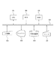
図2は、本実施形態に係る電子ファイリング装置の機能構成を示すブロック図である。図2おいて、1はイメージ分割処理機能部、2は部分画像抽出処理機能部、3は縮小画像合成処理機能部、4は文書登録機能部、5はファイル装置、6は表示制御機能部、7は選択機能部、8は入力装置、9は出力装置、10は文書読み込み機能部である。なお、各機能部は、外部記憶装置106からRAM103にロードされた制御プログラムをCPU101が実行し、スキャナ107や外部記憶装置106等を制御することにより実現される。
【0015】
図3は本実施形態による電子ファイリング装置の動作を説明するフローチャートである。以下、図2及び図3を参照して本実施形態の動作を説明する。
【0016】
まず、文書読み込み機能部10は、処理の対象となる文書イメージデータを、入力装置8(スキャナ107や外部記憶装置106等)から入力し、メモリ(RAM103)に格納する(ステップS11)。この文書イメージデータは、リアルタイムにスキャナ107により読み込まれた解像度400dpiのデータ、あるいは、予め読み込まれ、外部記憶装置106に格納されたデータのいずれであってもよい。
【0017】
イメージ分割処理機能部1は、RAM103に格納された文書イメージデータを、所定の分割数で均等割りすることにより、複数のイメージブロックに分割する(ステップS12)。
【0018】
本実施形態では、図4に示すようにA4サイズの画像20(特許公開公報の1ページ)を均等4分割している。図4は、RAM103に格納された文書イメージデータを示す概念図である。分割されたブロックをイメージブロックA,B,C,D(21から24)とする。これは、イメージ上の均等配置の4ヶ所より特徴を抜き出す為の分割である。
【0019】
部分画像抽出処理機能部2は、イメージ分割処理機能部1で分割した各イメージブロックから所定量(所定の大きさ)の部分画像を抽出する(ステップS13)。なお、その抽出量は、ディスプレイ105上の縮小画像の大きさと紙面上のオリジナルの画像大きさとの比で決まる。通常、縮小画像一覧表示では複数の縮小画像を表示する。例えば、17インチディスプレイ上において、約5cmとすると、8枚の縮小画像が表示可能になる。A4サイズに相当する画像は、幅が約20cmなので、一次元での縮小率は1/4に設定してある。すなわち、面積で1/16になる。従って、図4に示した各イメージブロックから1/16の面積だけをぬきだせば、4つのイメージブロックをあわせても、ディスプレイ上幅約5cmになる。
【0020】
従って、本実施形態では、図5に示されるように、各イメージブロックを16個の部分画像に均等に分割し、各イメージブロックから一つずつ部分画像を抜き取る。本実施形態では、選択機能部7が各イメージブロックの先頭の部分画像を選択するように設定されている。従って、図5の斜線が施された4ヶ所の部分画像(501〜504)が抽出されることになる。
【0021】
縮小画像合成処理機能部3は、部分画像抽出処理機能部2により抽出された部分画像を図6に示すように、縦にならべて一枚の縮小画像を構成し、メモリ(RAM103)へ格納する(ステップS14)。すなわち、上からイメージブロックA21よりの抽出部分画像601、イメージブロックB22よりの抽出部分画像602、イメージブロックC23よりの抽出部分画像603、イメージブロックD24よりの抽出部分画像604で構成される。そして、さらにこのように構成された合成画像を文字が判読できる範囲で縮小する。
【0022】
通常CRTの解像度は100dpi位なので、CRT上の1文字を認識できる大きさの限度は、1文字幅で約2mm位である。本実施形態で用いた原稿は特許公開公報であり、紙面上1文字の大きさが約2mm位である。本例では、解像度400dpiのスキャナ107でスキャンした画像なので、1/4に画像縮小をおこなう。そして、表示制御機能部6を介して、ディスプレイ105の画面上のウインドウ701に図7のように縮小画像(702,703)として表示する(ステップS15)。なお、図7では、上述した処理によって得られた縮小画像を表示している。
【0023】
そして、文書登録機能部4は、文書読み込み機能部10で読み込んだ文書のイメージデータと、縮小画像合成処理機能部3で処理された縮小画像とを関連付けてファイル装置5に登録する(ステップS16)。ファイル装置5は、文書のイメージデータとキーワードなどの文書管理情報とを関連付けてデータベースとして記憶する。また、表示制御機能部6は、ファイル装置5にて記憶した文字領域のイメージデータの出力装置9(ディスプレイ105など)への表示を制御する。尚、本実施形態ではディスプレイにCRTを用いているが、ディスプレイであればCRTに限らずLCDでもよい。
【0024】
以上説明したように、本実施形態によれば、1ページ中の複数領域より抽出された画像を、判読可能な範囲で縮小して提示するので、操作者は提示された文書の内容を容易に判断することが可能となる。すなわち、レイアウトが似ている文書や、あまり特徴のないレイアウトの文書でもその縮小面像だけで、一部ではあるが、文書全体にわたってその文字が認識できるため、容易に文書を識別できるようになる。
【0025】
なお、通常、文書には余白があり、上記の特許明細書の場合は、縦方向の上下に約1/16の大きさの余白が設定されている。これに対し、上述の実施形態で示した選択機能部7には一律に各イメージブロックの先頭部分を選択するように設定してある。このため、出来上がった縮小画像合成のイメージブロックA21とイメージブロックC23の部分には、図6の601、603に示されるように余白部分が抽出されてしまい、内容を表す情報量が減少して効果が半減してしまう(イメージブロックA21とイメージブロックC23の部分からは特徴が抜き出されていない)。
【0026】
従って、選択機能部7の設定値をイメージブロックA21とイメージブロックC23では先頭から2番目の部分画像を抽出し、イメージブロックB22とイメージブロックD24からは先頭の部分画像を抽出するように設定してもよい。このように設定すると、図8に示す斜線部分(801〜804)が抽出される対象になる。この結果、合成される縮小画像は図9に示すように、図8の部分画像801が抽出部分画像901、図8の部分画像802が抽出部分画像902、図8の部分画像803が抽出部分画像903、図8の部分画像804が抽出部分画像904となり、図6と比較して情報量を増加させることができる。
【0027】
(第2の実施形態)
以下に、添付の図面を参照して、本発明に係る第2の実施形態を詳細に説明する。
【0028】
装置構成の概略は、第1の実施例に説明した図1と同様の構成である。
【0029】
図13は、本実施形態に係る電子ファイリング装置の機能構成を示すブロック図である。図13において、1300は文字認識処理機能部,1301は全体文字列分割処理機能部、1302は部分文字列抽出処理機能部、1303は縮小画像合成処理機能部、1304は文書登録機能部、1305はファイル装置、1306は表示制御機能部、1307は選択機能部、1308は入力装置、1309は出力装置、1310は文書読み込み機能部を示す。なお、各機能部は、外部記憶装置106からRAM103にロードされた制御プログラムをCPU101が実行し、スキャナ107や外部記憶装置106等を制御することにより実現される。
【0030】
図14は本実施形態による電子ファイリング装置の動作を説明するフローチャートである。以下、図13及び図14を参照して本実施形態の動作を説明する。
【0031】
まず、文書読み込み機能部1310は、処理の対象となる文書イメージデータを、入力装置1308(スキャナ107や外部記憶装置106等)から入力し、メモリ(RAM103)に格納する(ステップS41)。この文書イメージデータは、リアルタイムにスキャナ107により読み込まれた解像度400dpiのデータ、あるいは、予め読み込まれ、外部記憶装置106に格納されたデータのいずれであってもよい。文字認識処理機能部1300はメモリ(RAM103)よりイメージを読み込み,認識した文字を出力する。本実施例の文字認識処理機能部1300は、2つ以上のスペースが連続する場合は、1つのスペースのみを出力し,行替え制御文字もスペース1つのみを出力する。したがって、文字認識処理機能部の出力はスペースを含まない連続文字の集合である文字列をスペースで結合したものである。言い換えれば出力は1ページ全体の文字列である(ステップ40)。
【0032】
イメージ処理機能部1301は、RAM103に格納された文字列を、所定の分割数で均等割りすることにより、複数の文字列ブロックに分割する(ステップS42)。
【0033】
本実施形態では、図15に示すようにA4サイズの画像420(特許公開公報の1ページ分の文字情報)を均等4分割している。図15は、RAM103に格納された部分文字列の分割と、部分文字列の抽出を説明する図である。分割されたブロックを文字列ブロックA,B,C,D(121から124)とする。これは、イメージ上の均等配置の4ヶ所より特徴を抜き出す為の分割である。部分文字列抽出処理機能部1302は、文字列分割処理機能部1301で分割した各文字列ブロックから所定量(所定の大きさ)の部分文字列を抽出する(ステップS43)。なお、抽出後の手順は、第1の実施形態で説明したのでここでは省略するが、ステップS44で抽出された部分文字列を合成し、ステップS45で合成画像を表示し、ステップS46で合成画像を登録する手順となる。
【0034】
図16の1602に、上述した処理によって得られた縮小画像を表示している。
【0035】
なお、上記において、選択機能部1307による抽出部分文字列の選択はマニュアルで設定することを前提とした。本実施形態では、フォントの種類,フォントサイズ,文字間,スペースが2ヶ以上あったら1ヶにするかしないか、行替え制御コード(CRLF:キャリッジリターン ラインフィード)をぬくか抜かないか、あるいは行間英文ワードラップのOn/OFF等はすべて固定とした。しかし、選択機能部1307のおのおのの設定を固定するか非固定にするかの選択が出来る様にする事は十分可能である。固定の場合は各々の任意設定をマニュアルで出来るのは当然であるが,非固定の場合には、処理対象の画像情報に応じて自動的に決定することも可能である。例えば、OSの標準文字サイズを拾って自動的に最適文字数を決定したり,逆に、文字数を指定してフォントサイズを調整したりする事も十分可能である。各文字列ブロックの分割数や部分文字列の文字数の取り方は手動で任意に取っても発明の範囲である。
【0036】
また、縮小画像に用いる部分文字列の位置を選択できるようにすることで、効果的に文書情報が得られるようになる。
【0037】
以上説明したように、本実施形態によれば、1ページ中の全体文字列を複数領域より抽出された部分的な文字列を、合成して縮小画像とするため,判読可能な範囲で文字が表示されるので、操作者は提示された文書の内容を容易に判断することが可能となる。すなわち、レイアウトが似ている文書や、あまり特徴のないレイアウトの文書でもその縮小面像だけで、一部ではあるが、縮小画像 全体にわたってその文字が認識できるため、容易に文書を識別できるようになる。
【0038】
更に、図16の1601に示すような、余白、改行によるスペース等を、図16の1602に示す図のように回避することが可能となり、情報量の多い縮小画像を提供することができる。
【0039】
(第3の実施形態)
以下に、添付の図面を参照して、本発明に係る好適な第3の実施形態を詳細に説明する。
【0040】
装置構成の概略は、第1の実施例に記載した図1と同様の構成である。
【0041】
図17は、本実施形態に係る電子ファイリング装置の機能構成を示すブロック図である。図17において、1700はアプリケーションデータ文字列抽出処理機能部,1701は全体文字列分割処理機能部、1702は部分文字列抽出処理機能部、1703は縮小画像合成処理機能部、1704は文書登録機能部、1705はファイル装置、1706は表示制御機能部、1707は選択機能部、1708は入力装置、1709は出力装置、1710はアプリケーションデータ読み込み機能部を示す。なお、各機能部は、外部記憶装置106からRAM103にロードされた制御プログラムをCPU101が実行し、外部記憶装置106を制御することにより実現される。
【0042】
図18は本実施形態による電子ファイリング装置の動作を説明するフローチャートである。以下、図17及び図18を参照して本実施形態の動作を説明する。
【0043】
アプリケーションデータ読み込み機能部1710は、INSOコーポレーション社の Outside In Viewer TechnologyというSoftwareモジュール等で構成されていて、アプリケーションソフトウェア( 例えばMicrosoft社によるMicrosoft Word)によって作成されたアプリケーションデータ(*.doc)を、入力装置1308(外部記憶装置106等)から入力し、メモリ(RAM103)に格納する(ステップS51)。尚、このSoftwareモジュールはすべてのアプリケーションデータを読み込めるわけではなく、あらかじめ読み込みたいアプリケーションに対応したフィルターをオプションインストールしておくことにより、それに対応したアプリケーションのアプリケーションデータを読み込むことが出来、アプリケーションデータの表示を行ったり、アプリケーションデータに含まれる文字を出力することが出来る。
【0044】
アプリケーションデータ文字列抽出処理機能部1700はメモリ(RAM103)よりアプリケーションデータ内の文字を読み込み,単語に変換する。本実施形態では2つ以上のスペースが連続する場合は1つのスペースに置き換えて出力し,行替え制御文字がある場合も1つのスペースに置き換える。したがって アプリケーションデータ文字列抽出処理機能部1700の出力は連続した文字列をスペースで結合したものである。本実施形態では先頭ページだけの文字列抽出処理を行うので、言い換えれば、出力は先頭ページ全体の文字列の集合である。その出力は図15の420となる(ステップS50)。
【0045】
全体文字列分割処理機能部1701は、RAM103に格納されたアプリケーションデータを、所定の分割数で均等割りすることにより、複数のイメージブロックに分割する(ステップS52)。
【0046】
本実施形態では図15に示すように印刷時A4サイズが適当な量の全体文字列420(特許公開公報の1ページ分の文字情報)を均等4分割している。分割されたブロックを文字列ブロックA,B,C,D(121から124)とする。これは、全体文字列上の均等配置の4ヶ所より特徴を抜き出す為の分割である。
【0047】
部分文字列抽出処理機能部1702は、全体文字列分割処理機能部1701で分割した各文字列ブロックから所定量(所定の文字だけ)の部分文字列を抽出する(ステップS53)。なお、抽出後の手順は、第1の実施形態で説明したのでここでは省略するが、ステップS54で抽出された部分文字列を合成し、ステップS55で合成画像を表示し、ステップS56で合成画像を登録する手順となる。
【0048】
図16の1602に、上述した処理によって得られた縮小画像を表示している。
【0049】
なお、上記において、選択機能部1707による抽出部分画像の選択はマニュアルで設定することを前提としたが自動でも構わない。詳細は第2の実施形態で説明したので省略する。
【0050】
また、上記実施形態では縮小画像合成処理機能部1703として合成文字列を画像に変換して画像として出力した例を示したが、合成文字列をそのまま表示制御機能部1706に文字として出力しても同様の効果は得られる。
【0051】
ここで、このようにして登録した文書のイメージデータと縮小画像を用いて、文書イメージを選択して表示する例を簡単に説明する。
【0052】
まず、文書イメージを選択するために、ユーザは、縮小画像の一覧の表示を入力装置104から指示する。この指示に基づき、CPU101は、外部記憶装置106に記憶されている縮小画像を順次読み出し、ディスプレイ105に一覧表示する。例えば、図7に示すように、ディスプレイ105上に縮小画像一覧ウインドウ701が表示され、このウインドウ内に縮小画像の一覧が表示される。ウインドウ701内に表示された縮小画像は、分割された位置が明確にわかるように、分割位置が画像とは異なる色の実線で表示される(704)。但し、実線が明確にわかる必要がないときは、この限りではない。
【0053】
ユーザは、一覧表示された縮小画像から1つの縮小画像の選択を、入力装置104から指示する。この指示に基づき、CPU101は、指示された縮小画像に対する文書イメージを、外部記憶装置から読み出し、ディスプレイ105上に、文書イメージ表示ウインドウを設定し、このウインドウ内に読み出した文書イメージを表示する。
【0054】
以上3つの実施形態によれば、例えば、図6や図9に示すように、所定の管理情報と関連付けて記憶された文書のイメージデータの検索、表示、印刷などを行なう電子ファイリング装置に好適な縮小画像の作成に関する内容であることが容易につかめる。
【0055】
本発明によれば、文書の一覧や検索結果リストなどの表示において、レイアウトが似ている文書や、あまり特徴のないレイアウトの文書でも容易に内容を識別できる縮小画像を作成できる。
【0056】
上記3つの実施形態において,1ページの文書に、1つの縮小画像を対応付けたが、複数ページからなる文書おいて、選択された1ページ(例えば、特許公開公報におけるフロントページ)において縮小画像を生成し、複数ページからなる文書と対応付けてもよい。
【0057】
なお、上記において、図2の選択機能部7、図13の選択機能部1307、図17の選択機能部1707による抽出部分画像の選択はマニュアルで設定することを前提としたが、処理対象の画像情報に応じて自動的に決定するようにもできる。例えば、図8のごとく分割されて得られた各部分画像について黒画素の量が所定値を越えるか否かを判定し、所定値を越える部分画像を採用するようにすればよい。
【0058】
なお、本実施形態に係る電子ファイリング装置には、上記以外にも、図2、図13、図17に示すファイル装置5、1305、1705に記憶された文書の情報に対して、検索、印刷などの機能を実現するための種々の構成要素が設けられているが、ここでは、それらの説明を省略する。
【0059】
また、上記実施形態では縮小画像として図6や図9に示す画像を表示するが、各ページのレイアウトに興味がある場合のために、操作者の指示により通常の縮小画像を表示する機能を合わせ持つようにしてもよいことはいうまでもない。
【0060】
本発明は、複数の機器(例えばホストコンピュータ、インタフェイス機器、リーダ、プリンタなど)から構成されるシステムに適用しても、一つの機器からなる装置(例えば、複写機、ファクシミリ装置など)に適用してもよい。
【0061】
また、本発明の目的は、前述した実施形態の機能を実現するソフトウェアのプログラムコードを記録した記憶媒体(または記録媒体)を、システムあるいは装置に供給し、そのシステムあるいは装置のコンピュータ(またはCPUやMPU)が記憶媒体に格納されたプログラムコードを読み出し実行することによっても、達成されることは言うまでもない。この場合、記憶媒体から読み出されたプログラムコード自体が前述した実施形態の機能を実現することになり、そのプログラムコードを記憶した記憶媒体は本発明を構成することになる。また、コンピュータが読み出したプログラムコードを実行することにより、前述した実施形態の機能が実現されるだけでなく、そのプログラムコードの指示に基づき、コンピュータ上で稼働しているオペレーティングシステム(OS)などが実際の処理の一部または全部を行い、その処理によって前述した実施形態の機能が実現される場合も含まれることは言うまでもない。
【0062】
さらに、記憶媒体から読み出されたプログラムコードが、コンピュータに挿入された機能拡張カードやコンピュータに接続された機能拡張ユニットに備わるメモリに書込まれた後、そのプログラムコードの指示に基づき、その機能拡張カードや機能拡張ユニットに備わるCPUなどが実際の処理の一部または全部を行い、その処理によって前述した実施形態の機能が実現される場合も含まれることは言うまでもない。
【0063】
【発明の効果】
以上説明したように、本発明によれば、文書の一覧や検索結果リストなどの表示において、レイアウトが似ている文書や、あまり特徴のないレイアウトの文書でも容易に内容を識別できる縮小画像を作成できる。
【図面の簡単な説明】
【図1】本実施形態に係る電子ファイリング装置の装置構成の概略を示すブロック図である。
【図2】本実施形態に係る電子ファイリング装置の機能構成を示すブロック図である。
【図3】本実施形態による電子ファイリング装置の動作を説明するフローチャートである。
【図4】文書イメージデータを示す概念図である。
【図5】本実施形態による部分画像への分割と、部分画像の抽出を説明する図である。
【図6】図5に示した抽出部分画像を用いて縮小画像を合成した状態を説明する図である。
【図7】本実施形態による縮小画像の表示形態を示す図である。
【図8】変形例による部分画像への分割と、部分画像の抽出を説明する図である。
【図9】図8に示した抽出部分画像を用いて縮小画像を合成した状態を説明する図である。
【図10】文書一覧や検索結果リストにおいて縮小画像を表示する、一般的な電子ファイリング装置の機能構成例を示す図である。
【図11】一般的な電子ファイリング装置における縮小画像による文書の一覧表示例を示す図である。
【図12】一般的な電子ファイリング装置における縮小画像による文書の一覧表示例を示す図である。
【図13】第2の実施形態に係る電子ファイリング装置の機能構成を示すブロック図である。
【図14】第2の実施形態による電子ファイリング装置の動作を説明するフローチャートである。
【図15】第2、第3の実施形態による部分文字列への分割と、部分文字列の抽出を説明する図である。
【図16】図5と図15に示した抽出部分画像あるいは部分文字列を用いて縮小画像を合成した状態を説明する図である。
【図17】第3の実施形態に係る電子ファイリング装置の機能構成を示すブロック図である。
【図18】第3の実施形態による電子ファイリング装置の動作を説明するフローチャートである。
【符号の説明】
101 CPU
102 ROM
103 RAM
104 入力装置
105 ディスプレイ
106 外部記憶装置
107 スキャナ[0001]
BACKGROUND OF THE INVENTION
The present invention relates to a reduced image creation method and apparatus suitable for an electronic filing apparatus that searches, displays, and prints image data of a document stored in association with predetermined management information.
[0002]
[Prior art]
2. Description of the Related Art Recently, electronic filing devices have been announced that store document management information in association with image data of a document created by reading the document with a scanner or the like, and search, display, print, and the like on the information. In such an electronic filing device, conventionally, as document management information, a document name, the number of pages, a registration date, a keyword, and the like are registered, and when a document list or a search result list is displayed, the document is identified. The document management information is displayed as the information.
[0003]
However, it is difficult to identify the outline of the document only with such document management information. Therefore, an electronic filing device has also been proposed that can create and register a reduced image of a document and display it in a document list or a search result list.
[0004]
FIG. 10 is a diagram illustrating a functional configuration example of a general electronic filing apparatus that displays a reduced image in a document list or a search result list. Such an electronic filing device includes, for example, a document
[0005]
[Problems to be solved by the invention]
However, in the above-described conventional electronic filing device, in the display of a list of documents or a search result list, the outline of the document can be identified from the reduced image of the document, but it is possible to identify only the layout of the entire document, The characters written in the document cannot be read. For this reason, there is a problem that it is very difficult to identify a document having a similar layout, a document having no large character or figure, and a layout with few features from the reduced image. For example, a reduced display example of the patent specification shown in FIG. 12 is a good example.
[0006]
In this example, two pages of a patent publication are displayed in a reduced image, and it is completely unknown what is written on both the left and right pages.
[0007]
The present invention has been made in view of the above-described problems, and the object of the present invention is to display a document with a similar layout or a document with a less characteristic layout in displaying a list of documents or a search result list. However, it is to create a reduced image whose contents can be easily identified.
[0008]
[Means for Solving the Problems]
In order to achieve the above object, a reduced image creating apparatus of the present invention has the following configuration, for example. I.e. multiple images Even A dividing unit that divides the image block, and a plurality of image blocks divided by the dividing unit; A certain percentage Extracting means for extracting a partial image, generating means for generating a composite image smaller than the image by combining a plurality of partial images extracted by the extracting means, and a composite image generated by the generating means To display on the display device Display control means for controlling.
[0009]
In order to achieve the above object, a reduced image creating apparatus having another configuration according to the present invention has the following configuration, for example.
[0010]
Character recognition means for recognizing a character from an image and outputting a character string; Even A dividing means for dividing into character string blocks, and a character string block divided by the dividing means. A predetermined percentage of the image block Extracting means for extracting a partial character string, and generating means for combining a plurality of partial character strings extracted by the extracting means, converting the combined character string into an image, and generating a composite image smaller than the image And a composite image generated by the generating means To display on the display device Display control means for controlling.
[0011]
DETAILED DESCRIPTION OF THE INVENTION
Hereinafter, three embodiments of the present invention will be described with reference to the accompanying drawings.
[0012]
(First embodiment)
FIG. 1 is a block diagram showing an outline of a device configuration of an electronic filing device according to this embodiment.
[0013]
An
[0014]
FIG. 2 is a block diagram illustrating a functional configuration of the electronic filing device according to the present embodiment. In FIG. 2, 1 is an image division processing function unit, 2 is a partial image extraction processing function unit, 3 is a reduced image composition processing function unit, 4 is a document registration function unit, 5 is a file device, 6 is a display control function unit, 7 is a selection function unit, 8 is an input device, 9 is an output device, and 10 is a document reading function unit. Each functional unit is realized by the
[0015]
FIG. 3 is a flowchart for explaining the operation of the electronic filing device according to the present embodiment. The operation of this embodiment will be described below with reference to FIGS.
[0016]
First, the document
[0017]
The image division
[0018]
In this embodiment, as shown in FIG. 4, an A4 size image 20 (one page of the patent publication) is equally divided into four. FIG. 4 is a conceptual diagram showing document image data stored in the
[0019]
The partial image extraction
[0020]
Therefore, in this embodiment, as shown in FIG. 5, each image block is equally divided into 16 partial images, and one partial image is extracted from each image block. In the present embodiment, the selection function unit 7 is set to select the top partial image of each image block. Therefore, the four partial images (501 to 504) indicated by hatching in FIG. 5 are extracted.
[0021]
The reduced image composition
[0022]
Usually, since the resolution of CRT is about 100 dpi, the limit of the size capable of recognizing one character on CRT is about 2 mm in width of one character. The document used in the present embodiment is a patent publication, and the size of one character on the paper is about 2 mm. In this example, since the image is scanned by the
[0023]
Then, the document registration function unit 4 registers the image data of the document read by the document
[0024]
As described above, according to the present embodiment, an image extracted from a plurality of areas in one page is presented in a reduced range within a legible range, so that the operator can easily display the contents of the presented document. It becomes possible to judge. In other words, even a document with a similar layout or a document with a less characteristic layout can be easily identified because the characters can be recognized throughout the entire document, although only a part of the reduced plane image. .
[0025]
Normally, a document has a margin, and in the case of the above-mentioned patent specification, a margin of about 1/16 size is set vertically in the vertical direction. On the other hand, the selection function unit 7 shown in the above-described embodiment is set so that the head portion of each image block is uniformly selected. For this reason, blank portions are extracted as shown in 601 and 603 in FIG. 6 in the portions of the image block A21 and the image block C23 of the reduced image composition thus completed, and the amount of information representing the content is reduced, which is effective. (The feature is not extracted from the image block A21 and the image block C23).
[0026]
Accordingly, the setting value of the selection function unit 7 is set so that the second partial image from the top is extracted in the image block A21 and the image block C23, and the first partial image is extracted from the image block B22 and the image block D24. Also good. With this setting, the hatched portions (801 to 804) shown in FIG. 8 are extracted. As a result, as shown in FIG. 9, the reduced image to be synthesized includes the
[0027]
(Second embodiment)
Hereinafter, a second embodiment according to the present invention will be described in detail with reference to the accompanying drawings.
[0028]
The outline of the apparatus configuration is the same as that of FIG. 1 described in the first embodiment.
[0029]
FIG. 13 is a block diagram showing a functional configuration of the electronic filing device according to the present embodiment. In FIG. 13, 1300 is a character recognition processing function unit, 1301 is an entire character string division processing function unit, 1302 is a partial character string extraction processing function unit, 1303 is a reduced image composition processing function unit, 1304 is a document registration function unit, and 1305 is A file device, 1306 is a display control function unit, 1307 is a selection function unit, 1308 is an input device, 1309 is an output device, and 1310 is a document reading function unit. Each functional unit is realized by the
[0030]
FIG. 14 is a flowchart for explaining the operation of the electronic filing device according to the present embodiment. The operation of this embodiment will be described below with reference to FIGS.
[0031]
First, the document
[0032]
The image
[0033]
In this embodiment, as shown in FIG. 15, an A4 size image 420 (character information for one page of the patent publication) is equally divided into four. FIG. 15 is a diagram for explaining the division of the partial character string stored in the
[0034]
A reduced image obtained by the above-described processing is displayed at 1602 in FIG.
[0035]
In the above description, it is assumed that selection of the extracted partial character string by the
[0036]
Also, by making it possible to select the position of the partial character string used for the reduced image, the document information can be obtained effectively.
[0037]
As described above, according to the present embodiment, since a partial character string obtained by extracting the entire character string in one page from a plurality of regions is combined into a reduced image, characters can be read within a legible range. Since it is displayed, the operator can easily determine the contents of the presented document. In other words, even a document with a similar layout or a document with a less characteristic layout can be recognized easily because the characters can be recognized over the entire reduced image, although only a part of the reduced surface image. Become.
[0038]
Furthermore, it is possible to avoid blanks, spaces due to line breaks, and the like as shown in 1601 of FIG. 16 as shown in the diagram of 1602 of FIG. 16, and a reduced image with a large amount of information can be provided.
[0039]
(Third embodiment)
A preferred third embodiment according to the present invention will be described below in detail with reference to the accompanying drawings.
[0040]
The outline of the apparatus configuration is the same as that of FIG. 1 described in the first embodiment.
[0041]
FIG. 17 is a block diagram illustrating a functional configuration of the electronic filing device according to the present embodiment. In FIG. 17, 1700 is an application data character string extraction processing function unit, 1701 is an entire character string division processing function unit, 1702 is a partial character string extraction processing function unit, 1703 is a reduced image composition processing function unit, and 1704 is a document registration function unit. 1705, a file device, 1706, a display control function unit, 1707, a selection function unit, 1708, an input device, 1709, an output device, and 1710, an application data reading function unit. Each functional unit is realized by the
[0042]
FIG. 18 is a flowchart for explaining the operation of the electronic filing device according to the present embodiment. Hereinafter, the operation of the present embodiment will be described with reference to FIGS. 17 and 18.
[0043]
The application data reading
[0044]
The application data character string extraction
[0045]
The entire character string division
[0046]
In this embodiment, as shown in FIG. 15, the entire character string 420 (character information for one page of the patent publication) having an appropriate A4 size at the time of printing is equally divided into four. Let the divided blocks be character string blocks A, B, C, and D (121 to 124). This is a division for extracting features from four equally arranged locations on the entire character string.
[0047]
The partial character string extraction
[0048]
A reduced image obtained by the above-described processing is displayed at 1602 in FIG.
[0049]
In the above description, the selection of the extracted partial image by the
[0050]
In the above-described embodiment, an example in which the combined character string is converted into an image and output as an image as the reduced image combining
[0051]
Here, an example of selecting and displaying a document image using the image data and reduced image of the document registered in this way will be briefly described.
[0052]
First, in order to select a document image, the user instructs display of a list of reduced images from the
[0053]
The user instructs the
[0054]
According to the above three embodiments, for example, as shown in FIG. 6 and FIG. 9, it is suitable for an electronic filing device that searches, displays, prints, etc. image data of a document stored in association with predetermined management information. It can be easily grasped that the content relates to creation of a reduced image.
[0055]
According to the present invention, when displaying a list of documents, a search result list, or the like, it is possible to create a reduced image that can easily identify the contents of a document having a similar layout or a document having a layout with little features.
[0056]
In the above three embodiments, one reduced image is associated with one page document. However, in a document consisting of a plurality of pages, the reduced image is displayed on one selected page (for example, the front page in the patent publication). It may be generated and associated with a document consisting of a plurality of pages.
[0057]
In the above description, selection of the extracted partial image by the selection function unit 7 in FIG. 2, the
[0058]
In addition to the above, the electronic filing apparatus according to the present embodiment can search, print, etc. for document information stored in the
[0059]
In the above embodiment, the images shown in FIG. 6 and FIG. 9 are displayed as reduced images. However, in the case where the user is interested in the layout of each page, a function for displaying a normal reduced image in accordance with an instruction from the operator is added. It goes without saying that you may have it.
[0060]
Even if the present invention is applied to a system composed of a plurality of devices (for example, a host computer, an interface device, a reader, a printer, etc.), it can be applied to an apparatus composed of a single device (for example, a copier, a facsimile machine, etc.). May be.
[0061]
Another object of the present invention is to supply a storage medium (or recording medium) in which a program code of software that realizes the functions of the above-described embodiments is recorded to a system or apparatus, and the computer (or CPU or CPU) of the system or apparatus. Needless to say, this can also be achieved by the MPU) reading and executing the program code stored in the storage medium. In this case, the program code itself read from the storage medium realizes the functions of the above-described embodiments, and the storage medium storing the program code constitutes the present invention. Further, by executing the program code read by the computer, not only the functions of the above-described embodiments are realized, but also an operating system (OS) running on the computer based on the instruction of the program code. It goes without saying that a case where the function of the above-described embodiment is realized by performing part or all of the actual processing and the processing is included.
[0062]
Furthermore, after the program code read from the storage medium is written into a memory provided in a function expansion card inserted into the computer or a function expansion unit connected to the computer, the function is determined based on the instruction of the program code. It goes without saying that the CPU or the like provided in the expansion card or the function expansion unit performs part or all of the actual processing and the functions of the above-described embodiments are realized by the processing.
[0063]
【The invention's effect】
As described above, according to the present invention, when displaying a list of documents, a search result list, or the like, a reduced image that can easily identify the contents of a document having a similar layout or a document having a layout with less features is created. it can.
[Brief description of the drawings]
FIG. 1 is a block diagram showing an outline of a device configuration of an electronic filing device according to an embodiment.
FIG. 2 is a block diagram showing a functional configuration of the electronic filing device according to the present embodiment.
FIG. 3 is a flowchart illustrating an operation of the electronic filing device according to the present embodiment.
FIG. 4 is a conceptual diagram showing document image data.
FIG. 5 is a diagram illustrating division into partial images and extraction of partial images according to the present embodiment.
6 is a diagram for explaining a state in which reduced images are synthesized using the extracted partial images shown in FIG. 5. FIG.
FIG. 7 is a diagram illustrating a display form of a reduced image according to the present embodiment.
FIG. 8 is a diagram illustrating division into partial images and extraction of partial images according to a modified example.
FIG. 9 is a diagram illustrating a state in which reduced images are synthesized using the extracted partial images illustrated in FIG.
FIG. 10 is a diagram illustrating a functional configuration example of a general electronic filing apparatus that displays a reduced image in a document list or a search result list.
FIG. 11 is a diagram illustrating a document list display example using reduced images in a general electronic filing device.
FIG. 12 is a diagram illustrating a document list display example using reduced images in a general electronic filing device.
FIG. 13 is a block diagram showing a functional configuration of an electronic filing device according to a second embodiment.
FIG. 14 is a flowchart for explaining the operation of the electronic filing device according to the second embodiment;
FIG. 15 is a diagram illustrating division into partial character strings and extraction of partial character strings according to the second and third embodiments.
16 is a diagram for explaining a state in which reduced images are synthesized using the extracted partial images or partial character strings shown in FIGS. 5 and 15. FIG.
FIG. 17 is a block diagram showing a functional configuration of an electronic filing device according to a third embodiment.
FIG. 18 is a flowchart illustrating the operation of the electronic filing device according to the third embodiment.
[Explanation of symbols]
101 CPU
102 ROM
103 RAM
104 Input device
105 display
106 External storage device
107 Scanner
Claims (19)
前記分割手段で分割された複数のイメージブロックのそれぞれから該イメージブロックの所定の割合の部分画像を抽出する抽出手段と、
前記抽出手段で抽出された複数の部分画像を合成して、前記画像よりも小さい合成画像を生成する生成手段と、
前記生成手段で生成された合成画像を表示装置に表示するよう制御する表示制御手段とを備えることを特徴とする縮小画像作成装置。A dividing means for dividing the image into a plurality of equal image blocks;
Extraction means for extracting a partial image of a predetermined ratio of the image block from each of the plurality of image blocks divided by the dividing means;
Generating means for combining a plurality of partial images extracted by the extracting means to generate a composite image smaller than the image;
Reduced image creating apparatus characterized by comprising a display control means for controlling so as to display the composite image generated by the generating unit on a display device.
前記抽出手段は、各イメージブロックそれぞれに設定された位置の部分画像を抽出することを特徴とする請求項1に記載の縮小画像作成装置。The dividing unit divides the image block into a plurality of equal partial images,
The reduced image creating apparatus according to claim 1, wherein the extracting unit extracts a partial image at a position set for each image block.
アプリケーションデータを読み込み、前記アプリケーションデータを抽出するアプリケーションデータ文字列抽出手段を更に有することを特徴とする請求項1に記載の縮小画像作成装置。The extraction means includes
The reduced image creation apparatus according to claim 1, further comprising an application data character string extraction unit that reads application data and extracts the application data.
前記分割工程で分割された複数のイメージブロックのそれぞれから該イメージブロックの所定の割合の部分画像を抽出手段が抽出する抽出工程と、
前記抽出工程で抽出された複数の部分画像を合成して、前記画像よりも小さい合成画像を生成手段が生成する生成工程と、
前記生成工程で生成された合成画像を表示装置に表示するよう表示制御手段が制御する表示制御工程と
を備えることを特徴とする縮小画像作成方法。A dividing step in which the dividing means divides the image into a plurality of equal image blocks;
An extraction step in which the extraction unit extracts a partial image of a predetermined ratio of the image block from each of the plurality of image blocks divided in the division step;
A generation step in which a plurality of partial images extracted in the extraction step are combined, and a generation unit generates a composite image smaller than the image,
And a display control step in which the display control means controls the composite image generated in the generation step to be displayed on a display device.
前記文字列を複数の均等な文字列ブロックに分割する分割手段と、
前記分割手段によって分割された文字列ブロックのそれぞれから該イメージブロックの所定の割合の部分文字列を抽出する抽出手段と、
前記抽出手段で抽出された複数の部分文字列を合成し、該合成された文字列を画像に変換し、前記画像よりも小さい合成画像を生成する生成手段と、
前記生成手段で生成された合成画像を表示装置に表示するよう制御する表示制御手段とを備えることを特徴とする縮小画像作成装置。Character recognition means for recognizing characters from an image and outputting a character string;
Dividing means for dividing the character string into a plurality of equal character string blocks;
Extraction means for extracting a partial character string of a predetermined ratio of the image block from each of the character string blocks divided by the dividing means;
Generating means for combining a plurality of partial character strings extracted by the extracting means, converting the combined character string into an image, and generating a composite image smaller than the image;
Reduced image creating apparatus characterized by comprising a display control means for controlling so as to display the composite image generated by the generating unit on a display device.
アプリケーションデータを読み込み、前記アプリケーションデータに含まれる文字列を抽出するアプリケーションデータ文字列抽出手段を更に有することを特徴とする請求項11に記載の縮小画像作成装置。The extraction means includes
12. The reduced image creating apparatus according to claim 11 , further comprising application data character string extraction means for reading application data and extracting a character string included in the application data.
前記文字列を複数の均等な文字列ブロックに分割手段が1分割する分割工程と、
前記分割工程で分割された文字列ブロックのそれぞれから該イメージブロックの所定の割合の部分文字列を抽出手段が抽出する抽出工程と、
前記抽出工程で抽出された複数の部分文字列を合成し、該合成された文字列を画像に変換し、前記画像よりも小さい合成画像を生成手段が生成する生成工程と、
前記生成工程で生成された合成画像を表示装置に表示するよう表示制御手段が制御する表示制御工程と
を備えることを特徴とする縮小画像作成方法。A character recognition step of recognizing characters from the image and outputting one character string from the character recognition means ;
A dividing step in which the dividing unit divides the character string into a plurality of equal character string blocks;
An extracting step in which the extracting means extracts a partial character string of a predetermined ratio of the image block from each of the character string blocks divided in the dividing step;
A generating step in which a plurality of partial character strings extracted in the extracting step are combined, the combined character string is converted into an image, and a generating unit generates a combined image smaller than the image;
And a display control step in which the display control means controls the composite image generated in the generation step to be displayed on a display device .
Priority Applications (3)
| Application Number | Priority Date | Filing Date | Title |
|---|---|---|---|
| JP2000135780A JP4310023B2 (en) | 1999-06-17 | 2000-05-09 | Reduced image creation method and apparatus, and storage medium |
| US09/593,775 US6996293B1 (en) | 1999-06-17 | 2000-06-14 | Reduced image forming method and apparatus |
| EP00305100.0A EP1061460B1 (en) | 1999-06-17 | 2000-06-16 | Partial image forming method and apparatus for filing documents |
Applications Claiming Priority (3)
| Application Number | Priority Date | Filing Date | Title |
|---|---|---|---|
| JP17157699 | 1999-06-17 | ||
| JP11-171576 | 1999-06-17 | ||
| JP2000135780A JP4310023B2 (en) | 1999-06-17 | 2000-05-09 | Reduced image creation method and apparatus, and storage medium |
Publications (3)
| Publication Number | Publication Date |
|---|---|
| JP2001061060A JP2001061060A (en) | 2001-03-06 |
| JP2001061060A5 JP2001061060A5 (en) | 2007-06-14 |
| JP4310023B2 true JP4310023B2 (en) | 2009-08-05 |
Family
ID=26494264
Family Applications (1)
| Application Number | Title | Priority Date | Filing Date |
|---|---|---|---|
| JP2000135780A Expired - Fee Related JP4310023B2 (en) | 1999-06-17 | 2000-05-09 | Reduced image creation method and apparatus, and storage medium |
Country Status (3)
| Country | Link |
|---|---|
| US (1) | US6996293B1 (en) |
| EP (1) | EP1061460B1 (en) |
| JP (1) | JP4310023B2 (en) |
Families Citing this family (8)
| Publication number | Priority date | Publication date | Assignee | Title |
|---|---|---|---|---|
| JP2008252289A (en) | 2007-03-29 | 2008-10-16 | Brother Ind Ltd | Image forming system, data processing apparatus, program, and image forming apparatus |
| JP5152031B2 (en) * | 2008-03-24 | 2013-02-27 | ブラザー工業株式会社 | Image processing apparatus and computer program |
| JP5736638B2 (en) * | 2008-10-20 | 2015-06-17 | 株式会社リコー | Image processing device |
| JP2011070601A (en) * | 2009-09-28 | 2011-04-07 | Fujitsu Ltd | Device, and method for managing image, and computer program |
| JP5594269B2 (en) | 2011-09-29 | 2014-09-24 | コニカミノルタ株式会社 | File name creation device, image forming device, and file name creation program |
| US8773733B2 (en) * | 2012-05-23 | 2014-07-08 | Eastman Kodak Company | Image capture device for extracting textual information |
| JP2013085276A (en) * | 2012-12-11 | 2013-05-09 | Pfu Ltd | Image processing device and image processing method |
| JP6609955B2 (en) * | 2015-03-27 | 2019-11-27 | 日本電気株式会社 | Image processing apparatus, image processing method, and program |
Family Cites Families (21)
| Publication number | Priority date | Publication date | Assignee | Title |
|---|---|---|---|---|
| GB2030823B (en) * | 1978-10-02 | 1982-11-03 | Ibm | Image data manipulation apparatus |
| JPS60134357A (en) * | 1983-12-21 | 1985-07-17 | Hitachi Ltd | Image file registration/search method |
| JPH063608B2 (en) * | 1984-06-30 | 1994-01-12 | 株式会社東芝 | Document image editing device |
| US4850026A (en) * | 1987-10-13 | 1989-07-18 | Telecommunications Laboratories Dir. Gen'l Of Telecom. Ministry Of Communications | Chinese multifont recognition system based on accumulable stroke features |
| EP0385009A1 (en) * | 1989-03-03 | 1990-09-05 | Hewlett-Packard Limited | Apparatus and method for use in image processing |
| JP2722803B2 (en) * | 1990-10-01 | 1998-03-09 | 松下電器産業株式会社 | Document creation device |
| GB9103080D0 (en) * | 1991-02-14 | 1991-04-03 | British And Foreign Bible The | Analysing textual documents |
| JP2579397B2 (en) * | 1991-12-18 | 1997-02-05 | インターナショナル・ビジネス・マシーンズ・コーポレイション | Method and apparatus for creating layout model of document image |
| JP3253356B2 (en) * | 1992-07-06 | 2002-02-04 | 株式会社リコー | Document image area identification method |
| JP3338107B2 (en) * | 1993-02-22 | 2002-10-28 | 富士写真フイルム株式会社 | Image processing device for micro film reader |
| US5424853A (en) * | 1993-04-19 | 1995-06-13 | Sharp Kabushiki Kaisha | Image processing apparatus |
| JP3443146B2 (en) * | 1993-11-15 | 2003-09-02 | 株式会社リコー | Image combining method and image recording device |
| US5517587A (en) * | 1994-09-23 | 1996-05-14 | International Business Machines Corporation | Positioning method and apparatus for line scanned images |
| JPH08214201A (en) * | 1994-11-28 | 1996-08-20 | Canon Inc | Image pickup device |
| US5717940A (en) | 1995-04-28 | 1998-02-10 | Ricoh Company, Ltd. | Method of selecting a target document using features of an example page |
| JP3504054B2 (en) * | 1995-07-17 | 2004-03-08 | 株式会社東芝 | Document processing apparatus and document processing method |
| US5682441A (en) | 1995-11-08 | 1997-10-28 | Storm Technology, Inc. | Method and format for storing and selectively retrieving image data |
| US6167410A (en) * | 1997-01-30 | 2000-12-26 | Casio Computer Co., Ltd. | Document processing apparatus for adding predetermined design types to an original document |
| SG71018A1 (en) * | 1997-03-01 | 2000-03-21 | Inst Of Systems Science Nat Un | Robust identification code recognition system |
| US6356314B1 (en) * | 1997-03-10 | 2002-03-12 | Komatsu Ltd. | Image synthesizing device and image conversion device for synthesizing and displaying an NTSC or other interlaced image in any region of a VCA or other non-interlaced image |
| US6301386B1 (en) * | 1998-12-09 | 2001-10-09 | Ncr Corporation | Methods and apparatus for gray image based text identification |
-
2000
- 2000-05-09 JP JP2000135780A patent/JP4310023B2/en not_active Expired - Fee Related
- 2000-06-14 US US09/593,775 patent/US6996293B1/en not_active Expired - Fee Related
- 2000-06-16 EP EP00305100.0A patent/EP1061460B1/en not_active Expired - Lifetime
Also Published As
| Publication number | Publication date |
|---|---|
| US6996293B1 (en) | 2006-02-07 |
| EP1061460A2 (en) | 2000-12-20 |
| EP1061460B1 (en) | 2013-08-14 |
| EP1061460A3 (en) | 2003-04-23 |
| JP2001061060A (en) | 2001-03-06 |
Similar Documents
| Publication | Publication Date | Title |
|---|---|---|
| EP0703524B1 (en) | Variable data fields in a page description language | |
| JP4995057B2 (en) | Drawing apparatus, printing apparatus, drawing method, and program | |
| US8134739B2 (en) | Information processing device for outputting reduced-size pages | |
| US20080186537A1 (en) | Information processing apparatus and method for controlling the same | |
| US20030202716A1 (en) | Image processing apparatus, method, and system | |
| US10303409B2 (en) | Information processing apparatus, information processing method, and storage medium | |
| US20070127085A1 (en) | Printing system, printing method and program thereof | |
| JP4310023B2 (en) | Reduced image creation method and apparatus, and storage medium | |
| US8331736B2 (en) | Image processing device and method therefor | |
| JP2662305B2 (en) | Figure selection method | |
| JP2004214991A (en) | Document image data management system, its program, its apparatus, and its method | |
| US8004712B2 (en) | Image processing apparatus and method | |
| JP7314627B2 (en) | CONTROL DEVICE, IMAGE FORMING APPARATUS, CONTROL METHOD AND CONTROL PROGRAM | |
| JP4433963B2 (en) | Print data generation apparatus and print data generation method | |
| JPH05108793A (en) | Document edition device | |
| JP2001202362A (en) | Character editing processor | |
| US20020186396A1 (en) | Image processing apparatus, image processing system and image processing program storage medium | |
| JPH0877376A (en) | Image processing method and device therefor | |
| JPH07262317A (en) | Document processor | |
| JP4323885B2 (en) | Printing apparatus, printing control method, storage medium, and program | |
| JPH0493275A (en) | Image filing device | |
| JP2005167522A (en) | Printing system | |
| JP2001086320A (en) | Method for information processing and information processor | |
| JP3927766B2 (en) | Image processing apparatus and method | |
| JP3313906B2 (en) | Print media saving method in electronic editing system |
Legal Events
| Date | Code | Title | Description |
|---|---|---|---|
| A521 | Request for written amendment filed |
Free format text: JAPANESE INTERMEDIATE CODE: A523 Effective date: 20070423 |
|
| A621 | Written request for application examination |
Free format text: JAPANESE INTERMEDIATE CODE: A621 Effective date: 20070423 |
|
| A977 | Report on retrieval |
Free format text: JAPANESE INTERMEDIATE CODE: A971007 Effective date: 20080812 |
|
| A131 | Notification of reasons for refusal |
Free format text: JAPANESE INTERMEDIATE CODE: A131 Effective date: 20080826 |
|
| A521 | Request for written amendment filed |
Free format text: JAPANESE INTERMEDIATE CODE: A523 Effective date: 20081023 |
|
| TRDD | Decision of grant or rejection written | ||
| A01 | Written decision to grant a patent or to grant a registration (utility model) |
Free format text: JAPANESE INTERMEDIATE CODE: A01 Effective date: 20090428 |
|
| A01 | Written decision to grant a patent or to grant a registration (utility model) |
Free format text: JAPANESE INTERMEDIATE CODE: A01 |
|
| A61 | First payment of annual fees (during grant procedure) |
Free format text: JAPANESE INTERMEDIATE CODE: A61 Effective date: 20090511 |
|
| R150 | Certificate of patent or registration of utility model |
Free format text: JAPANESE INTERMEDIATE CODE: R150 |
|
| FPAY | Renewal fee payment (event date is renewal date of database) |
Free format text: PAYMENT UNTIL: 20120515 Year of fee payment: 3 |
|
| FPAY | Renewal fee payment (event date is renewal date of database) |
Free format text: PAYMENT UNTIL: 20120515 Year of fee payment: 3 |
|
| FPAY | Renewal fee payment (event date is renewal date of database) |
Free format text: PAYMENT UNTIL: 20130515 Year of fee payment: 4 |
|
| FPAY | Renewal fee payment (event date is renewal date of database) |
Free format text: PAYMENT UNTIL: 20140515 Year of fee payment: 5 |
|
| LAPS | Cancellation because of no payment of annual fees |