JP4309332B2 - Projection display - Google Patents
Projection display Download PDFInfo
- Publication number
- JP4309332B2 JP4309332B2 JP2004344866A JP2004344866A JP4309332B2 JP 4309332 B2 JP4309332 B2 JP 4309332B2 JP 2004344866 A JP2004344866 A JP 2004344866A JP 2004344866 A JP2004344866 A JP 2004344866A JP 4309332 B2 JP4309332 B2 JP 4309332B2
- Authority
- JP
- Japan
- Prior art keywords
- state
- lens group
- lens
- fly
- refractive power
- Prior art date
- Legal status (The legal status is an assumption and is not a legal conclusion. Google has not performed a legal analysis and makes no representation as to the accuracy of the status listed.)
- Expired - Fee Related
Links
- 230000003287 optical effect Effects 0.000 claims description 91
- 238000005286 illumination Methods 0.000 claims description 56
- 230000014509 gene expression Effects 0.000 claims description 31
- 230000004907 flux Effects 0.000 claims description 9
- 230000001678 irradiating effect Effects 0.000 claims 1
- 238000010586 diagram Methods 0.000 description 21
- 230000004075 alteration Effects 0.000 description 14
- 210000003644 lens cell Anatomy 0.000 description 8
- 238000000926 separation method Methods 0.000 description 7
- 238000000034 method Methods 0.000 description 4
- 238000005452 bending Methods 0.000 description 2
- 239000012141 concentrate Substances 0.000 description 2
- 238000003384 imaging method Methods 0.000 description 2
- 239000004973 liquid crystal related substance Substances 0.000 description 2
- 239000000463 material Substances 0.000 description 2
- 125000006850 spacer group Chemical group 0.000 description 2
- 230000015572 biosynthetic process Effects 0.000 description 1
- 210000004027 cell Anatomy 0.000 description 1
- 230000000052 comparative effect Effects 0.000 description 1
- 238000011156 evaluation Methods 0.000 description 1
- 229910052736 halogen Inorganic materials 0.000 description 1
- 150000002367 halogens Chemical class 0.000 description 1
- 229910001507 metal halide Inorganic materials 0.000 description 1
- 150000005309 metal halides Chemical class 0.000 description 1
- 230000002093 peripheral effect Effects 0.000 description 1
- 238000003786 synthesis reaction Methods 0.000 description 1
Images


Classifications
-
- H—ELECTRICITY
- H04—ELECTRIC COMMUNICATION TECHNIQUE
- H04N—PICTORIAL COMMUNICATION, e.g. TELEVISION
- H04N5/00—Details of television systems
- H04N5/74—Projection arrangements for image reproduction, e.g. using eidophor
-
- G—PHYSICS
- G03—PHOTOGRAPHY; CINEMATOGRAPHY; ANALOGOUS TECHNIQUES USING WAVES OTHER THAN OPTICAL WAVES; ELECTROGRAPHY; HOLOGRAPHY
- G03B—APPARATUS OR ARRANGEMENTS FOR TAKING PHOTOGRAPHS OR FOR PROJECTING OR VIEWING THEM; APPARATUS OR ARRANGEMENTS EMPLOYING ANALOGOUS TECHNIQUES USING WAVES OTHER THAN OPTICAL WAVES; ACCESSORIES THEREFOR
- G03B21/00—Projectors or projection-type viewers; Accessories therefor
- G03B21/005—Projectors using an electronic spatial light modulator but not peculiar thereto
Description
本発明は、フライアイレンズを含む照明光学装置およびそれを用いた投射型表示装置に関するものである。 The present invention relates to an illumination optical device including a fly-eye lens and a projection display device using the same.
たとえば、液晶表示装置を備えた投射型表示装置(プロジェクタ)等に適用される照明光学装置は、一対のフライアイレンズを含んで構成される。
一対のフライアイレンズを含む照明光学装置では、光源による照明光を一対のフライアイレンズにより光量分布を均一化して、たとえば空間光変調素子としての液晶表示パネル等の被照射面に照射する。
For example, an illumination optical device applied to a projection display device (projector) provided with a liquid crystal display device includes a pair of fly-eye lenses.
In an illumination optical device including a pair of fly-eye lenses, the illumination light from the light source is made uniform with a pair of fly-eye lenses to irradiate a surface to be irradiated such as a liquid crystal display panel as a spatial light modulator.
この種の照明光学装置として、たとえば照射光の方向を変えるミラーを含む装置が提案されている(たとえば特許文献1参照)。 As this type of illumination optical device, for example, a device including a mirror that changes the direction of irradiation light has been proposed (see, for example, Patent Document 1).
ところで、反射型表示素子を用いた投射型表示装置には様々なサイズの画像表示素子があり、また画像表示素子の大きさに合わせて様々な光路長をもつTIRプリズムや色分離合成プリズムが使用されている。
この場合、画像表示素子やプリズムの変更に合わせて照明光学系を開発するにあたり、光学素子の配置が異なるなるため、照明光学装置の筐体を個別に開発していた。そのため金型投資が膨大なり開発コストを圧迫していた。
By the way, projection display devices using reflective display elements have image display elements of various sizes, and TIR prisms and color separation / synthesis prisms having various optical path lengths according to the size of the image display elements are used. Has been.
In this case, when the illumination optical system is developed in accordance with the change of the image display element and the prism, the arrangement of the optical elements is different. Therefore, the housing of the illumination optical device has been individually developed. For this reason, investment in molds has become enormous, putting pressure on development costs.
このような課題を解決する目的として、以下に示すような投射型表示装置の設計方法が知られている。
この投射型表示装置の設計方法は、光源と、映像表示素子と、照明光学系と、投射レンズと、光学ユニット構造体を有する投射型画像表示装置において、光学ユニット構造体は光源から画像表示素子までの所定の距離を略等しく保ちながら同アスペクト比で表示サイズが異なる少なくとも2種類の画像像表示素子から選択される1種類を装着し、照明光学系は複数の光学素子のうち少なくとも1つの光学素子を、装着した画像表示素子に対応させて、画像表示素子上の照明光学系による照射領域が画像表示の表示サイズに略合致する所定の位置に装着する。
As a purpose for solving such a problem, a method for designing a projection display device as described below is known.
In this projection display device design method, a light source, an image display element, an illumination optical system, a projection lens, and a projection type image display apparatus having an optical unit structure, the optical unit structure is changed from the light source to the image display element. 1 type selected from at least two types of image image display elements having different display sizes with the same aspect ratio while maintaining a predetermined distance to be substantially equal, and the illumination optical system is at least one of a plurality of optical elements. The element is mounted in a predetermined position corresponding to the mounted image display element so that the irradiation area by the illumination optical system on the image display element substantially matches the display size of the image display.
この設計方法は、光源から画像表示素子の距離を一定に保ち、異なる大きさで同じアスペクト比の画像表示素子を使用することで、照明光学系の筐体を共通化している。
これにより、共通な光学ユニット構造体を用いて異なる表示エリアサイズの映像素子にそれぞれ対応した照明光学系・投射光学系を構成できる。
Accordingly, it is possible to configure illumination optical systems and projection optical systems respectively corresponding to video elements having different display area sizes using a common optical unit structure.
しかしながら、上述した投射型表示装置の設計方法によれば、たとえば3板式DMD(Digital Micro Mirror Device)の照明光学系の場合、画面アスペクト比が異なり、画面サイズの異なるDMDを使用すると色分離合成プリズムやTIRプリズムの光路長やサイズが異なるため、照明光学系筐体を共通化することができない。 However, according to the design method of the projection display device described above, for example, in the case of a three-plate DMD (Digital Micro Mirror Device) illumination optical system, if DMDs having different screen aspect ratios and different screen sizes are used, a color separation / combination prism is used. Since the optical path length and size of the TIR prism are different, the illumination optical system housing cannot be shared.
本発明の目的は、画像表示素子の形状やプリズム内光路長が異なる場合においても、共通の筐体で照明光学系を収納することが可能な投射型表示装置を提供することにある。 An object of the present invention is to provide a projection display device that can accommodate an illumination optical system in a common housing even when the shape of the image display element and the optical path length in the prism are different.
前記目的を達成するため、本発明の観点の投射型表示装置は、照明光を出射する光源と、画像表示素子と、前記光源による照明光を前記画像表示素子に照射する照明光学系と、前記画像表示素子により形成された画像を投射する投射光学系と、を有し、前記照明光学系は、互いの焦点位置に配置される第1フライアイレンズおよび第2のフライアイレンズと、第1のレンズ群と、前記第1のレンズ群と光路を折り曲げるミラーを挟んで配置される第2のレンズ群と、を有し、所定の第1の状態の照明光学系と、当該第1の状態の照明光学系と同じ焦点距離で異なるバックフォーカスを有し、かつ下記の条件式を満足する第2の状態の照明光学系とが交換可能となるように共通の筐体内に収納可能である。
e1=−(φ−φ11−φ12)/(φ11×φ12) …(1)
e2=−(φ−φ21−φ22)/(φ21×φ22) …(2)
φ11=(1−fb1×φ)/e1 …(3)
φ21=(1−fb2×φ)/e2 …(4)
0.95< e1/e2 < 1.05 …(5)
1.1×(1−e1×φ)/φ< fb1 <f×0.9 …(6)
1.1×(1−e2×φ)/φ< fb2 <f×0.9 …(7)
ここで、φは第1および第2のレンズ群(以下、「リレーレンズ系」という)全体の屈折力(焦点距離の逆数)、φ11は第1の状態の第1のレンズ群屈折力、φ12は第1の状態の第2のレンズ群屈折力、φ21は第2の状態の第1のレンズ群屈折力、φ22は第2の状態の第2のレンズ群屈折力、e1は第1の状態での第1のレンズ群と第2のレンズ群の近軸的な群間隔、e2は第2の状態での第1のレンズ群と第2のレンズ群の近軸的な群間隔、f:リレーレンズ系全体の焦点距離、fb1:第1の状態で、無限遠光束に対するリレーレンズ系の近軸バックフォーカス、fb2は第2の状態で、無限遠光束に対するリレーレンズ系の近軸バックフォーカスをそれぞれ示している。
To achieve the above object, a projection display device according to an aspect of the present invention includes a light source that emits illumination light, an image display element, an illumination optical system that irradiates the image display element with illumination light from the light source, and A projection optical system for projecting an image formed by the image display element, wherein the illumination optical system includes a first fly-eye lens and a second fly-eye lens arranged at the focal positions of each other, and a first And a first lens group and a second lens group disposed with a mirror that bends the optical path, the illumination optical system in a predetermined first state , and the first state The illumination optical system can be stored in a common housing so that the illumination optical system in the second state having the same focal length and different back focus and satisfying the following conditional expression can be exchanged .
e1 = − (φ−φ11−φ12) / (φ11 × φ12) (1)
e2 = − (φ−φ21−φ22) / (φ21 × φ22) (2)
φ11 = (1−fb1 × φ) / e1 (3)
φ21 = (1−fb2 × φ) / e2 (4)
0.95 <e1 / e2 <1.05 (5)
1.1 × (1-e1 × φ) / φ <fb1 <f × 0.9 (6)
1.1 × (1-
Here, φ is the refractive power (the reciprocal of the focal length) of the entire first and second lens groups (hereinafter referred to as “relay lens system”), φ11 is the first lens group refractive power in the first state, and φ12. Is the second lens group refractive power in the first state, φ21 is the first lens group refractive power in the second state, φ22 is the second lens group refractive power in the second state, and e1 is the first state. , A paraxial group spacing between the first lens group and the second lens group, e2 is a paraxial group spacing between the first lens group and the second lens group in the second state, and f: The focal length of the entire relay lens system, fb1: The paraxial back focus of the relay lens system for an infinite luminous flux in the first state, and fb2 the paraxial back focus of the relay lens system for an infinite luminous flux in the second state. Each is shown.
好適には、前記光源側から順に、照明光の光路に沿って、前記第1のフライアイレンズ、第2のフライアイレンズ、第1のレンズ群、ミラー、および第2のレンズ群が配置されている。 Preferably, the first fly-eye lens, the second fly-eye lens, the first lens group, the mirror, and the second lens group are arranged in order from the light source side along the optical path of the illumination light. ing.
好適には、前記第1および第2の状態において、前記第1のフライアイレンズ、第2のフライアイレンズ、第1のレンズ群の入射面、ミラーが折り返し作用を受けていない同一光軸上において光源側から順に配置され、第1の状態におけるミラーから第2のレンズ群の光入射面までの距離d1と、第2の状態におけるミラーから第2のレンズ群の光入射面までの距離d2が略等しく設定されている Preferably, in the first and second states, the first fly-eye lens, the second fly-eye lens, the entrance surface of the first lens group, and the mirror on the same optical axis not subjected to the folding action The distance d1 from the mirror in the first state to the light incident surface of the second lens group and the distance d2 from the mirror to the light incident surface of the second lens group in the second state Are set to be approximately equal
好適には、前記第2のレンズ群の照明光が出射する側にプリズムが配置される。 Preferably, a prism is disposed on the side of the second lens group from which illumination light is emitted.
好適には、前記照明光学系を収納する筐体を備え、前記照明光学系が筐体の所定の長さ方向に配置され、前記第1の状態の照明光学系と前記第2の照明光学系とが交換可能である。 Preferably, a housing for housing the illumination optical system is provided, the illumination optical system is disposed in a predetermined length direction of the housing, and the illumination optical system in the first state and the second illumination optical system Are interchangeable.
好適には、前記第1のレンズ群および第2のレンズ群はリレーレンズ系を形成し、前記第1および第2のフライアイレンズと前記リレーレンズ系の焦点距離の比率が前記第1の状態と前記第2の状態とで一定に保持されている。
Preferably, the first lens group and the second lens group form a relay lens system, and a ratio of focal lengths of the first and second fly-eye lenses and the relay lens system is the first state. And the second state are held constant.
本発明によれば、画像表示素子の形状やプリズム内光路長が異なる場合においても、共通の筐体で照明光学系を収納することができる。 According to the present invention, the illumination optical system can be housed in a common housing even when the shape of the image display element and the optical path length in the prism are different.
以下、本発明の実施形態を添付図面に関連付けて説明する。 Hereinafter, embodiments of the present invention will be described with reference to the accompanying drawings.
<第1実施形態>
図1は、本発明に係る投射型表示装置の第1の状態の構成と第2の状態の構成を並列に記載した光学系の第1の実施形態を示す図であって、図1(A)が第1の状態の構成を、図1(B)が第2の状態の構成をそれぞれ示している。
なお、本実施形態において、距離、長さ、間隔等の単位はmmである。
<First Embodiment>
FIG. 1 is a diagram showing a first embodiment of an optical system in which a configuration in a first state and a configuration in a second state of a projection display device according to the present invention are described in parallel, and FIG. ) Shows the configuration in the first state, and FIG. 1B shows the configuration in the second state.
In this embodiment, the unit of distance, length, interval, etc. is mm.
本実施形態の投射型表示装置100は、基本的に、光源101、アパーチャ102、コリメータレンズ103、第1のフライアイレンズ104、第2のフライアイレンズ105、第1のリレーレンズ群(第1のレンズ群という場合もある)106、折り返しミラー107、第2のリレーレンズ群(第2のレンズ群という場合もある)108、TIRプリズム109、色分離合成プリズム110、および反射型画像表示素子111を有している。
そして、本実施形態の第1の状態における投射型表示装置100−1は、光源101−1、アパーチャ102−1、コリメータレンズ103−1、第1のフライアイレンズ104−1、第2のフライアイレンズ105−1、第1のリレーレンズ群(第1のレンズ群という場合もある)106−1、折り返しミラー107−1、第2のリレーレンズ群(第2のレンズ群という場合もある)108−1、TIRプリズム109−1、色分離合成プリズム110−1、および反射型画像表示素子111−1を有している。
同様に、本実施形態の第2の状態における投射型表示装置100−2は、光源101−2、アパーチャ102−2、コリメータレンズ103−2、第1のフライアイレンズ104−2、第2のフライアイレンズ105−2、第1のリレーレンズ群106−2、折り返しミラー107−2、第2のリレーレンズ群108−2、TIRプリズム109−2、色分離合成プリズム110−2、および反射型画像表示素子111−2を有している。
The
The projection display device 100-1 in the first state of the present embodiment includes a light source 101-1, an aperture 102-1, a collimator lens 103-1, a first fly-eye lens 104-1, and a second fly. Eye lens 105-1, first relay lens group (sometimes referred to as first lens group) 106-1, folding mirror 107-1, second relay lens group (sometimes referred to as second lens group). 10-1, a TIR prism 109-1, a color separation / combination prism 110-1, and a reflective image display element 111-1.
Similarly, the projection display device 100-2 in the second state of the present embodiment includes a light source 101-2, an aperture 102-2, a collimator lens 103-2, a first fly-eye lens 104-2, a second Fly-eye lens 105-2, first relay lens group 106-2, folding mirror 107-2, second relay lens group 108-2, TIR prism 109-2, color separation / combination prism 110-2, and reflection type It has an image display element 111-2.
本実施形態の第1および第2の状態の投射型表示装置100−1,100−2において、第1のフライアイレンズ104(−1,−2)と第2のフライアレイレンズ105)−1、−2)は互いの焦点位置に配置される。
また、本実施形態の第1および第2の状態の投射型表示装置100−1,100−2において、光路を折り曲げるミラー107(−1,−2)を挟んで第1のリレーレンズ群106(−1,−2)と第2のリレーレンズ群108(−1,−2)が配置される。
In the projection display devices 100-1 and 100-2 in the first and second states of the present embodiment, the first fly-eye lens 104 (-1, -2) and the second fly-array lens 105) -1. , -2) are arranged at the focal positions of each other.
In the first and second projection display apparatuses 100-1 and 100-2 of the present embodiment, the first relay lens group 106 (with the mirror 107 (-1, -2) that bends the optical path sandwiched therebetween. −1, −2) and the second relay lens group 108 (−1, −2) are arranged.
そして、本実施形態の投射型表示装置は、画像表示素子形状やプリズム内の光路長が異なる場合においてもレンズの筐体を共通化することができるように、上述したように、第1のフライアイレンズと第2のフライアイレンズを互いの焦点位置に配置するとともに、同じ焦点距離、異なるバックフォーカスのリレーレンズ系を同じ配置にしている。 As described above, the projection display device according to the present embodiment can share the lens housing even when the image display element shape and the optical path length in the prism are different. The eye lens and the second fly-eye lens are arranged at the focal positions of each other, and relay lens systems having the same focal length and different back focus are arranged in the same arrangement.
具体的には、光路長の異なるプリズムに対応するために、同じ焦点距離でバックフォーカスの異なる二つの第1および第2のリレーレンズ群を実現するときに、それぞれのレンズ群が下記の条件式を満たすように構成される。 Specifically, when realizing two first and second relay lens groups having the same focal length and different back focus in order to correspond to prisms having different optical path lengths, each lens group has the following conditional expression: Configured to meet.
(数1)
e1=−(φ−φ11−φ12)/(φ11×φ12) …(1)
e2=−(φ−φ21−φ22)/(φ21×φ22) …(2)
φ11=(1−fb1×φ)/e1 …(3)
φ21=(1−fb2×φ)/e2 …(4)
0.95< e1/e2 < 1.05 …(5)
1.1×(1−e1×φ)/φ< fb <f×0.9 …(6)
(Equation 1)
e1 = − (φ−φ11−φ12) / (φ11 × φ12) (1)
e2 = − (φ−φ21−φ22) / (φ21 × φ22) (2)
φ11 = (1−fb1 × φ) / e1 (3)
φ21 = (1−fb2 × φ) / e2 (4)
0.95 <e1 / e2 <1.05 (5)
1.1 × (1-e1 × φ) / φ <fb <f × 0.9 (6)
ここで、φはリレーレンズ系全体の屈折力(焦点距離の逆数)、φ11は第1の状態の第1のレンズ群屈折力、φ12は第1の状態の第2のレンズ群屈折力、φ21は第2の状態の第1のレンズ群屈折力、φ22は第2の状態の第2のレンズ群屈折力、e1は第1の状態での第1のレンズ群と第2のレンズ群の近軸的な群間隔、e2は第2の状態での第1のレンズ群と第2のレンズ群の近軸的な群間隔、fb1:第1の状態で、無限遠光束に対するリレーレンズ系の近軸バックフォーカス、fb2は第2の状態で、無限遠光束に対するリレーレンズ系の近軸バックフォーカスをそれぞれ示している。 Here, φ is the refractive power of the entire relay lens system (reciprocal of focal length), φ11 is the first lens group refractive power in the first state, φ12 is the second lens group refractive power in the first state, and φ21. Is the first lens group refractive power in the second state, φ22 is the second lens group refractive power in the second state, and e1 is the distance between the first lens group and the second lens group in the first state. An axial group interval, e2 is a paraxial group interval between the first lens group and the second lens group in the second state, and fb1: a proximity of the relay lens system to the infinity light beam in the first state. Axial back focus, fb2, indicates the paraxial back focus of the relay lens system for the infinite light beam in the second state.
これにより、所定の第1の状態に対し、条件式を満足する第2の状態に変更することが可能である。
以上の条件を満足することにより、本実施形態の投射型表示装置においては、各光学素子の形状は変更されても共通の筐体で光学素子を配置できる光学系を提供している。
As a result, the predetermined first state can be changed to the second state that satisfies the conditional expression.
By satisfying the above conditions, the projection display device of the present embodiment provides an optical system in which the optical elements can be arranged in a common housing even if the shape of each optical element is changed.
上記の条件式(1)〜(5)は、二つの異なるリレーレンズ系が同じ焦点距離を有し、かつ異なるバックフォーカスを有する場合に、第1のレンズ群と第の2レンズ群の近軸関係を示している。
式(1)〜(4) は一般的な近軸式であり、式(5) は第1の状態と第2の状態で第1のレンズ群と第2のレンズ群の間隔が大きく変化せず筐体が共通化できる条件を示している。
これにより、焦点距離を維持した状態でバックフォーカスだけを変更できるためプリズムの光路長の変更に対応することができる。
The above conditional expressions (1) to (5) indicate that the paraxial axes of the first lens group and the second lens group when two different relay lens systems have the same focal length and different back focus. Showing the relationship.
Equations (1) to (4) are general paraxial equations, and in Equation (5), the distance between the first lens group and the second lens group varies greatly between the first state and the second state. This shows the conditions under which the chassis can be shared.
As a result, only the back focus can be changed while maintaining the focal length, so that it is possible to cope with a change in the optical path length of the prism.
式(6)は第1のレンズ群と第2のレンズ群の屈折力が適切に配分され、リレーレンズ系として良好な結像性能を有するための条件である。
バックフォーカスが式(6)の下限を下回ると第2のレンズ群の屈折力が弱くなり、屈折力が第1群に片寄り収差補正上好ましくない。また、バックフォーカスが上限を超えると第1のレンズ群の屈折力が弱くなり、第2のレンズ群に屈折力が片寄り同様に好ましくない。
Equation (6) is a condition for appropriately allocating the refractive powers of the first lens group and the second lens group and having good imaging performance as a relay lens system.
If the back focus is less than the lower limit of the expression (6), the refractive power of the second lens group becomes weak, and the refractive power is not preferable for the first group in terms of correcting the deviation aberration. If the back focus exceeds the upper limit, the refractive power of the first lens group becomes weak, and the refractive power of the second lens group is not preferable as well.
画像表示素子サイズが変更される場合に、フライアイレンズの配置を一定に保つためには、2枚のフライアイレンズは、同一形状、同一材料であり互いの略焦点位置に配置され、画像表示素子の変更に伴いセル形状だけが変更される、という条件を満足することが必要である。
照明光学系の照明領域は、第1のフライアイレンズのレンズセル開口形状が第2フライアイレンズとリレーレンズ系によって画像表示素子上に拡大投影されることで形成される。拡大の倍率は第2フライアイレンズの焦点距離とリレーレンズ系の焦点距離の比率で決まることから、フライアイレンズとリレーレンズ系の焦点距離を一定に保つことによって、拡大倍率を一定に保つことができる。倍率を一定に保つことによって、画像表示素子のサイズ変更に対しては、フライアイレンズセルの開口形状を変更することによって対応することが可能になる。
リレーレンズ系焦点距離を一定にすることで、互いの配置は画像表示素子の形状やリレーレンズ系のバックフォーカスとは無関係に、互いの配置を常に一定にすることができる。
In order to keep the fly-eye lens arrangement constant when the image display element size is changed, the two fly-eye lenses have the same shape and the same material and are arranged at substantially the focal positions of each other, and the image display It is necessary to satisfy the condition that only the cell shape is changed as the element is changed.
The illumination area of the illumination optical system is formed by enlarging and projecting the lens cell aperture shape of the first fly-eye lens on the image display element by the second fly-eye lens and the relay lens system. Since the magnification is determined by the ratio of the focal length of the second fly-eye lens and the focal length of the relay lens system, the magnification is kept constant by keeping the focal length of the fly-eye lens and the relay lens system constant. Can do. By keeping the magnification constant, the size change of the image display element can be dealt with by changing the aperture shape of the fly-eye lens cell.
By making the focal length of the relay lens system constant, the mutual arrangement can always be made constant irrespective of the shape of the image display element and the back focus of the relay lens system.
以上のように、2枚のフライアイレンズを互いの焦点位置に配置し、リレーレンズ群のパワー配置が条件式(1)〜(6)を満たすようにすれば、共通の筐体で画像表示素子サイズやプリズム光路長の変更に対応することが可能になる。
以下に、図1の各部の具体的な構成および機能、並びに、条件式の具体的な値に基づく評価、考察について順を追って説明する。
As described above, if two fly-eye lenses are arranged at the focal positions of each other and the power arrangement of the relay lens group satisfies the conditional expressions (1) to (6), an image is displayed in a common housing. It becomes possible to cope with changes in element size and prism optical path length.
In the following, the specific configuration and function of each part in FIG. 1 and the evaluation and consideration based on the specific values of the conditional expressions will be described in order.
なお、図1において、画像表示素子111(−1,−2)は、DMDなどの反射型画像表示素子であり画像表示領域がそれぞれ異なる。また、TIRプリズム109(−1,−2)と色分離合成プリズム110(−1,−2)は、それぞれ光路長が異なる。 In FIG. 1, an image display element 111 (-1, -2) is a reflective image display element such as a DMD, and has different image display areas. The TIR prism 109 (-1, -2) and the color separation / combination prism 110 (-1, -2) have different optical path lengths.
光源101(−1,−2)は、たとえばハロゲンランプ、メタルハライドランプや回転楕円リフレクタを含んで構成され、白色光の照明光を出射する。
アパーチャ102(−1,−2)は、矩形開口を有し、光源101による照明光のうちの不要な光束を遮断する。図には示していないが、光源101の回転楕円体リフクレタからの収斂光がアパーチャ102に入射する。
コリメータレンズ103(−1,−2)は、アパーチャ102に入射した収斂光を平行光束に変換して第1のフライアイレンズ104に出射する。
なお、上記の回転楕円体リフクレタ、アパーチャ102、コリメータレンズ103からなる構成を、回転放物面リフレクタの光源によっても構成することができる。
The light source 101 (-1, -2) includes, for example, a halogen lamp, a metal halide lamp, and a spheroid reflector, and emits white illumination light.
The apertures 102 (-1, -2) have a rectangular opening, and block unnecessary light beams from the illumination light from the light source 101. Although not shown in the drawing, convergent light from the spheroid lifter of the light source 101 enters the aperture 102.
The collimator lens 103 (−1, −2) converts the convergent light incident on the aperture 102 into a parallel light beam and emits it to the first fly-
The configuration composed of the spheroid reflector, the aperture 102, and the collimator lens 103 can also be configured by a light source of a rotating paraboloid reflector.
第1のフライアイレンズ104(−1,−2)および第2のフライアイレンズ105(−1,−2)は、材質、厚さ、レンズセル面形状を同じにすることで同一の焦点距離を有し、互いの焦点位置に配置することで、第1の状態と第2の状態で同じ位置関係を保っている。
また、レンズセル開口形状を画像表示素子形状と略相似形状にすることで異なるサイズの画像表示素子に対応している。
The first fly-eye lens 104 (-1, -2) and the second fly-eye lens 105 (-1, -2) have the same focal length by using the same material, thickness, and lens cell surface shape. And the same positional relationship is maintained in the first state and the second state.
Further, the lens cell opening shape is made to be substantially similar to the image display element shape, thereby corresponding to image display elements of different sizes.
第1のレンズ群106(−1,−2)と第2のレンズ群108(−1,−2)はリレーレンズ系を形成し、それぞれ第1のレンズ群106(−1,−2)と第2のレンズ群108(−1,−2)がミラー107(−1,−2)を挟んで配置されている。
リレーレンズ全体の焦点距離は、第1の状態と第2の状態で等しく、バックフォーカスはそれぞれのプリズムの光路長に合わせて異なっている。
The first lens group 106 (−1, −2) and the second lens group 108 (−1, −2) form a relay lens system, and the first lens group 106 (−1, −2) and The second lens group 108 (-1, -2) is arranged with the mirror 107 (-1, -2) in between.
The focal length of the entire relay lens is the same in the first state and the second state, and the back focus is different according to the optical path length of each prism.
図1中の破線は、各光学素子が第1の状態と第2の状態で同じ配置になっていることを示している。
図1に示すように、第1のフライアイレンズ104(−1,−2)と、第2のフライアイレンズ105(−1,−2)、リレーレンズ系の第1のレンズ群106(−1,−2) の入射面、ミラー107(−1,−2)が折り返し作用を受けていない同一光軸上においてコリメータレンズ103(−1,−2)側から順番に配置されている。
そして、第1の状態におけるミラー107−1から第2のリレーレンズ群108−1の光入射面までの間隔(距離)d1と、第2の状態におけるミラー108−2から第2のリレーレンズ群108−2の光入射面までの間隔(距離)d2を共通に(等しく;d1≒d2)することで筐体共通化を図っている。
また、同一集光角のランプを用いれば、アパ−チャ102、コリメータレンズ103についても図1に示すごとく配置を同一にすることができる。
The broken lines in FIG. 1 indicate that the optical elements are arranged in the same manner in the first state and the second state.
As shown in FIG. 1, a first fly-eye lens 104 (-1, -2), a second fly-eye lens 105 (-1, -2), and a first lens group 106 (- 1, -2) and the mirror 107 (-1, -2) are arranged in order from the collimator lens 103 (-1, -2) side on the same optical axis not subjected to the folding action.
The distance (distance) d1 from the mirror 107-1 to the light incident surface of the second relay lens group 108-1 in the first state, and the second relay lens group from the mirror 108-2 in the second state. The case (2) is common to the intervals (distances) d2 to the light incident surface of 108-2 (equal; d1≈d2).
If lamps having the same condensing angle are used, the arrangement of the aperture 102 and the collimator lens 103 can be the same as shown in FIG.
以下に示す表1は、本第1の実施形態の近軸配置の上記式(1)〜(6)の条件式における各パラメータの具体的な値の一例を示している。この例は、条件式を満足する例である。 Table 1 shown below shows an example of specific values of each parameter in the conditional expressions (1) to (6) in the paraxial arrangement of the first embodiment. This example is an example that satisfies the conditional expression.

表1に示すように、第1の状態(状態1)における各パラメータは次のように設定されている。
リレー系全体の屈折力φの逆数(1/φ)が“162.0”、第1のレンズ群106−1の屈折力の逆数(1/φ11)が“265.07”、第1のレンズ群106−1と第2のレンズ群108−1の近軸的な群間隔e1が“109.77”、第2のレンズ群108−1の屈折力の逆数(1/φ12)が“244.21”、無限遠光束に対するリレーレンズ系の近軸バックフォーカスfb1が“94.93”にそれぞれ設定されている。
As shown in Table 1, the parameters in the first state (state 1) are set as follows.
The reciprocal (1 / φ) of the refractive power φ of the entire relay system is “162.0”, the reciprocal of the refractive power (1 / φ11) of the first lens group 106-1 is “265.07”, and the first lens The paraxial group interval e1 between the group 106-1 and the second lens group 108-1 is “109.77”, and the reciprocal of the refractive power (1 / φ12) of the second lens group 108-1 is “244. The paraxial back focus fb1 of the relay lens system for 21 "and infinity light flux is set to" 94.93 ", respectively.
同様に、第2の状態(状態2)における各パラメータは次のように設定されている。
リレー系全体の屈折力φの逆数(1/φ)が“162.0”、第1のレンズ群106−2の屈折力の逆数(1/φ21)が“482.1”、第1のレンズ群106−2と第2のレンズ群108−2の近軸的な群間隔e2が“105.29”、第2のレンズ群108−2の屈折力の逆数(1/φ22)が“190.71”、無限遠光束に対するリレーレンズ系の近軸バックフォーカスfb2が“126.62”にそれぞれ設定されている。
Similarly, each parameter in the second state (state 2) is set as follows.
The reciprocal (1 / φ) of the refractive power φ of the entire relay system is “162.0”, the reciprocal of the refractive power (1 / φ21) of the first lens group 106-2 is “482.1”, and the first lens. The paraxial group interval e2 between the group 106-2 and the second lens group 108-2 is “105.29”, and the reciprocal of the refractive power (1 / φ22) of the second lens group 108-2 is “190. 71 ", the paraxial back focus fb2 of the relay lens system for the infinity light beam is set to" 126.62 ", respectively.
表1のように各パラメータが設定されている第1の実施形態の投射型表示装置100における“e1/e2”が“1.04”であり、条件式(5)で規定する範囲にあり、条件を満足している。
また、バックフォーカスfbの最大値Fbmaxが“145.8(162×0.9)”、第1の状態におけるバックフォーカスfbの最小値Fbmin1が“57.45”、第2の状態におけるバックフォーカスfbの最小値Fbmin2が“62.38”となり、条件式(6)で規定する範囲にあり、条件を満足している。
“E1 / e2” in the
The maximum value Fbmax of the back focus fb is “145.8 (162 × 0.9)”, the minimum value Fbmin1 of the back focus fb in the first state is “57.45”, and the back focus fb in the second state. The minimum value Fbmin2 is “62.38”, which is in the range defined by the conditional expression (6), and satisfies the condition.
図2(A),(B)は、本第1の実施形態に係るリレーレンズ系の保持部材を示す構成図であり、円筒の断面を示している。図2(A)が第1の状態に対応し、図2(B)が第2の状態に対応している。 FIGS. 2A and 2B are configuration diagrams showing a holding member of the relay lens system according to the first embodiment, showing a cross section of a cylinder. FIG. 2A corresponds to the first state, and FIG. 2B corresponds to the second state.
保持部材200は、所定の角度に折れ曲がった筒状に形成されており、ミラー107が取り付けされる屈曲部分201は、所定の角度で切断されている。
第1のリレーレンズ群106と第2リレーレンズ群108はそれぞれミラー107を挟んでフライアイレンズ側とTIRプリズム側から組み込む構造になっている。
具体的には、屈曲した保持部材200の一端側(フライアイレンズ側)の開口部202に第1のリレーレンズ群106が組み込まれ、他端側(TIRプリズム側)の開口部203に第2のリレーレンズ群108が組み込まれている。
The holding
The first
Specifically, the first
このような構造をとることにより、本第1の実施形態に係る投射型表示装置100においては、第1のリレーレンズ群106の射出面頂点と第2のリレーレンズ群108の入射頂点間隔が共通になっており、これにより、共通の筐体でリレーレンズを組み込むことが可能になる。
曲率の差により筐体のレンズ保持面から面頂点までの高さにわずかなずれが生じるが、簡単なスペ−サによって補正することができ、またレンズ面高さを考慮してスペ−サの不要な設計を行うことも可能である。
By adopting such a structure, in the
Although there is a slight shift in the height from the lens holding surface of the housing to the top of the surface due to the difference in curvature, it can be corrected by a simple spacer, and the height of the spacer is taken into account. Unnecessary design can also be performed.
図3(A) ,(B)は、本第1の実施形態における第1の状態および第2の状態のリレーレンズ系の光路図である。
図からわかるように、本第1の実施形態の投射型表示装置100においては、平行光が画像表示素子111−1,111−2上で結像している。
3A and 3B are optical path diagrams of the relay lens system in the first state and the second state in the first embodiment.
As can be seen from the figure, in the
図4(A),(B)は、第1フライアイレンズが第2フライアイレンズの焦点位置に配置されることによる光束の状態を示す図である。
図4(A),(B)からわかるように、本第1の実施形態の投射型表示装置100は、第1フライアイレンズ104−1,104−2が第2フライアイレンズ105−1,105−2の焦点位置に配置されることにより、第1フライアイレンズ表面から射出した光束が平行になる。
FIGS. 4A and 4B are views showing the state of the light flux when the first fly-eye lens is arranged at the focal position of the second fly-eye lens.
As can be seen from FIGS. 4A and 4B, in the
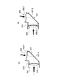
図5(A),(B)は、図3(A),(B)および図4(A),(B)を統合した図であって、第1のフライアイレンズ表面が第2フライアイレンズとリレーレンズにより画像表示素子111−1,111−2上に結像される様子を、中心のレンズセルと周辺レンズセルについて示している。 5A and 5B are diagrams in which FIGS. 3A and 3B and FIGS. 4A and 4B are integrated, and the surface of the first fly-eye lens is the second fly-eye. A state in which an image is formed on the image display elements 111-1 and 111-2 by the lens and the relay lens is shown for the central lens cell and the peripheral lens cell.
図6は、第1の実施形態の第1の状態の光路における画像表示素子の照明状態を示す図である。
図7は、第1の実施形態の第2の状態の光路における画像表示素子の照明状態を示す図である。
図6および図7より、本第1の実施形態の投射型表示装置100においては、異なる大きさの画像表示素子を共通の筐体で正確に照明していることが分かる。
FIG. 6 is a diagram illustrating an illumination state of the image display element in the optical path in the first state according to the first embodiment.
FIG. 7 is a diagram illustrating an illumination state of the image display element in the optical path in the second state according to the first embodiment.
6 and 7 that the
表2は第1の実施形態の第1の状態の光学データを示し、表3は同じく第2の状態の光学データを示している。
表2および表3に示すように、第1の実施形態の投射型表示装置100は、フライアイレンズの配置は同じであるが、レンズセルの大きさを変更することで、異なる大きさの画像表示素子に対応している。
Table 2 shows the optical data in the first state of the first embodiment, and Table 3 shows the optical data in the second state.
As shown in Tables 2 and 3, the
<第2実施形態>
図8は、本発明に係る投射型表示装置の第1の状態の構成と第2の状態の構成を並列に記載した光学系の第2の実施形態を示す図であって、図8(A)が第1の状態の構成を、図8(B)が第2の状態の構成をそれぞれ示している。
Second Embodiment
FIG. 8 is a diagram showing a second embodiment of the optical system in which the configuration of the first state and the configuration of the second state of the projection display device according to the present invention are described in parallel, and FIG. ) Shows the configuration in the first state, and FIG. 8B shows the configuration in the second state.
本第2の実施形態の投射型表示装置100Aは、基本的な構成は第1の実施形態の投射型表示装置100と同様の構成を有する。
第2の実施形態の投射型表示装置100Aが第1の実施形態と異なる点は、第1の実施形態の構成とリレーレンズの焦点距離、レンズ群の間隔を、上記条件式(1)〜(6)を満たす範囲で、筐体の共通化が可能であることを示している。
The
The
以下に示す表4は、本第2の実施形態の近軸配置の上記式(1)〜(6)の条件式における各パラメータの具体的な値の一例を示している。この例は、条件式を満足する例である。 Table 4 shown below shows an example of specific values of each parameter in the conditional expressions (1) to (6) in the paraxial arrangement of the second embodiment. This example is an example that satisfies the conditional expression.
表4に示すように、第1の状態(状態1)における各パラメータは次のように設定されている。
リレー系全体の屈折力φの逆数(1/φ)が“200.0”、第1のレンズ群106−1の屈折力の逆数(1/φ11)が“234.23”、第1のレンズ群106−1と第2のレンズ群108−1の近軸的な群間隔e1が“117.67”、第2のレンズ群108−1の屈折力の逆数(1/φ12)が“682.40”、無限遠光束に対するリレーレンズ系の近軸バックフォーカスfb1が“93.00”にそれぞれ設定されている。
As shown in Table 4, each parameter in the first state (state 1) is set as follows.
The reciprocal (1 / φ) of the refractive power φ of the entire relay system is “200.0”, the reciprocal of the refractive power (1 / φ11) of the first lens group 106-1 is “234.23”, and the first lens The paraxial group distance e1 between the group 106-1 and the second lens group 108-1 is "117.67", and the reciprocal (1 / φ12) of the refractive power of the second lens group 108-1 is "682. The paraxial back focus fb1 of the relay lens system for 40 "and infinity light flux is set to" 93.00 ", respectively.
同様に、第2の状態(状態2)における各パラメータは次のように設定されている。
リレー系全体の屈折力φの逆数(1/φ)が“200.0”、第1のレンズ群106−2の屈折力の逆数(1/φ21)が“342.47”、第1のレンズ群106−2と第2のレンズ群108−2の近軸的な群間隔e2が“120.58”、第2のレンズ群108−2の屈折力の逆数(1/φ22)が“311.37”、無限遠光束に対するリレーレンズ系の近軸バックフォーカスfb2が“126.6”にそれぞれ設定されている。
Similarly, each parameter in the second state (state 2) is set as follows.
The reciprocal (1 / φ) of the refractive power φ of the entire relay system is “200.0”, the reciprocal of the refractive power (1 / φ21) of the first lens group 106-2 is “342.47”, and the first lens. The paraxial group interval e2 between the group 106-2 and the second lens group 108-2 is “120.58”, and the reciprocal (1 / φ22) of the refractive power of the second lens group 108-2 is “311. The paraxial back focus fb2 of the relay lens system for 37 "and infinity light flux is set to" 126.6 ", respectively.
表4のように各パラメータが設定されている第2の実施形態の投射型表示装置100Aにおける“e1/e2”が“0.976”であり、条件式(5)で規定する範囲にあり、条件を満足している。
また、バックフォーカスfbの最大値Fbmaxが“180(200×0.9)”、第1の状態におけるバックフォーカスfbの最小値Fbmin1が“90.56”、第2の状態におけるバックフォーカスfbの最小値Fbmin2が“87.36”となり、条件式(6)で規定する範囲にあり、条件を満足している。
“E1 / e2” in the
Further, the maximum value Fbmax of the back focus fb is “180 (200 × 0.9)”, the minimum value Fbmin1 of the back focus fb in the first state is “90.56”, and the minimum value of the back focus fb in the second state is The value Fbmin2 is “87.36”, which is in the range specified by the conditional expression (6), and satisfies the condition.
表5は第2の実施形態の第1の状態の光学データを示し、表6は同じく第2の状態の光学データを示している。
表5および表6に示すように、第2の実施形態の投射型表示装置100Aは、フライアイレンズの配置は同じであるが、レンズセルの大きさを変更することで、異なる大きさの画像表示素子に対応している。
Table 5 shows the optical data in the first state of the second embodiment, and Table 6 shows the optical data in the second state.
As shown in Tables 5 and 6, the
図9は、第2の実施形態の第1の状態の光路における画像表示素子の照明状態を示す図である。
図10は、第2の実施形態の第2の状態の光路における画像表示素子の照明状態を示す図である。
図9および図10より、本第2の実施形態の投射型表示装置100Aにおいては、異なる大きさの画像表示素子の領域を均等に(共通の筐体で正確に)照明していることが分かる。
FIG. 9 is a diagram illustrating an illumination state of the image display element in the optical path in the first state according to the second embodiment.
FIG. 10 is a diagram illustrating an illumination state of the image display element in the optical path in the second state according to the second embodiment.
From FIG. 9 and FIG. 10, it can be seen that in the
<第3実施形態>
図11は、本発明に係る投射型表示装置の第1の状態の構成と第2の状態の構成を並列に記載した光学系の第3の実施形態を示す図であって、図11(A)が第1の状態の構成を、図11(B)が第2の状態の構成をそれぞれ示している。
<Third Embodiment>
FIG. 11 is a diagram showing a third embodiment of the optical system in which the configuration of the first state and the configuration of the second state of the projection display device according to the present invention are described in parallel. ) Shows the configuration in the first state, and FIG. 11B shows the configuration in the second state.
本第3の実施形態の投射型表示装置100Bは、基本的な構成は第1および第2の実施形態の投射型表示装置100,100Aと同様の構成を有する。
第3の実施形態の投射型表示装置100Bが第1および第2の実施形態と異なる点は、上記条件式(5)を満足しておらず、筐体を共通化することができないことを示し、第1および第2の実施形態に対する比較例として示している。
The projection
The
以下に示す表7は、本第3の実施形態の近軸配置の上記式(1)〜(6)の条件式における各パラメータの具体的な値の一例を示している。この例は、条件式を満足していない例である。 Table 7 shown below shows an example of specific values of each parameter in the conditional expressions (1) to (6) in the paraxial arrangement of the third embodiment. In this example, the conditional expression is not satisfied.
表7に示すように、第1の状態(状態1)における各パラメータは次のように設定されている。
リレー系全体の屈折力φの逆数(1/φ)が“200.0”、第1のレンズ群106−1の屈折力の逆数(1/φ11)が“215.17”、第1のレンズ群106−1と第2のレンズ群108−1の近軸的な群間隔e1が“103.18”、第2のレンズ群108−1の屈折力の逆数(1/φ12)が“1469.93”、無限遠光束に対するリレーレンズ系の近軸バックフォーカスfb1が“93.00”にそれぞれ設定されている。
As shown in Table 7, the parameters in the first state (state 1) are set as follows.
The reciprocal (1 / φ) of the refractive power φ of the entire relay system is “200.0”, the reciprocal of the refractive power (1 / φ11) of the first lens group 106-1 is “215.17”, and the first lens The paraxial group interval e1 between the group 106-1 and the second lens group 108-1 is “103.18”, and the reciprocal (1 / φ12) of the refractive power of the second lens group 108-1 is “1469. 93 ", the paraxial back focus fb1 of the relay lens system for the infinity light beam is set to" 93.00 ", respectively.
同様に、第2の状態(状態2)における各パラメータは次のように設定されている。
リレー系全体の屈折力φの逆数(1/φ)が“200.0”、第1のレンズ群106−2の屈折力の逆数(1/φ21)が“342.47”、第1のレンズ群106−2と第2のレンズ群108−2の近軸的な群間隔e2が“120.58”、第2のレンズ群108−2の屈折力の逆数(1/φ22)が“311.37”、無限遠光束に対するリレーレンズ系の近軸バックフォーカスfb2が“126.6”にそれぞれ設定されている。
Similarly, each parameter in the second state (state 2) is set as follows.
The reciprocal (1 / φ) of the refractive power φ of the entire relay system is “200.0”, the reciprocal of the refractive power (1 / φ21) of the first lens group 106-2 is “342.47”, and the first lens. The paraxial group interval e2 between the group 106-2 and the second lens group 108-2 is “120.58”, and the reciprocal (1 / φ22) of the refractive power of the second lens group 108-2 is “311. The paraxial back focus fb2 of the relay lens system for 37 "and infinity light flux is set to" 126.6 ", respectively.
表7のように各パラメータが設定されている第3の実施形態の投射型表示装置100Bにおける“e1/e2”が“0.856”であり、条件式(5)で規定する範囲の下限値0.95より小さい値であり、条件式(5)を満足していない。
また、バックフォーカスfbの最大値Fbmaxが“180(200×0.9)”、第1の状態におけるバックフォーカスfbの最小値Fbmin1が“106.5”、第2の状態におけるバックフォーカスfbの最小値Fbmin2が“87.36”となり、条件式(6)で規定する範囲を満足していない。
“E1 / e2” is “0.856” in the
Further, the maximum value Fbmax of the back focus fb is “180 (200 × 0.9)”, the minimum value Fbmin1 of the back focus fb in the first state is “106.5”, and the minimum value of the back focus fb in the second state is The value Fbmin2 is “87.36”, which does not satisfy the range specified by the conditional expression (6).
表8は第2の実施形態の第1の状態の光学データを示し、表9は同じく第2の状態の光学データを示している。 Table 8 shows the optical data in the first state of the second embodiment, and Table 9 shows the optical data in the second state.
上述したように、本第3の実施形態の投射型表示装置100Bは、条件式(5)の下限値な超えた場合の例であり、第1のレンズ群106と第2のレンズ群108の間隔が10mm変化していることがわかる。この場合、筐体を共通化することができない。
As described above, the
<第4実施形態>
第4の実施形態としてレンズ頂点間隔を一定としてバックフォーカスを変化させてリレーレンズ系を設計した場合に、条件式(6)の値の変化について調べる。
<Fourth embodiment>
In the fourth embodiment, when the relay lens system is designed by changing the back focus with the lens vertex interval constant, the change in the value of the conditional expression (6) is examined.
図12(A),(B),(C)は、焦点距離200mmで配置を一定にしてバックフォーカスを変動させた場合の光路図である。図12(A),(B),(C)においては、ミラーによる折り曲げを省略し、プリズム光路を空気換算し図示している。 FIGS. 12A, 12B, and 12C are optical path diagrams when the back focus is fluctuated with a constant arrangement at a focal length of 200 mm. 12A, 12B, and 12C, the bending by the mirror is omitted, and the prism optical path is shown in air.
この場合、図12(A)に示すように、焦点距離に対してバックフォーカスを短くすると第2のレンズ群108の屈折力が弱くなり、屈折力が第1のレンズ群106に片寄る。絞りに近い第1のレンズ群106に屈折力が集中するため、像面湾曲が発生し、照明エリアの矩形境界線がディフォーカスし好ましくない。
逆に、図12(C)に示すように、バックフォーカスが焦点距離に近くなると、第2のレンズ群108に屈折力が集中する。この場合、絞りに近い位置にある第1のレンズ群106の屈折力が弱いために球面収差が発生し、照明エリア境界線が全体的にボケて幅が広くなり好ましくない。これはボケが広い場合は、境界線が鮮鋭な場合に比べて、有効な領域を確保するために照明エリアを広くとる必要があるからである。
以上の理由により条件式(6)を満足する必要がある。
In this case, as shown in FIG. 12A, when the back focus is shortened with respect to the focal length, the refractive power of the
Conversely, as shown in FIG. 12C, the refractive power concentrates on the
For the above reason, it is necessary to satisfy the conditional expression (6).
図12(A),(B),(C)のパワー配置を表10に示す。合わせてバツクフォーカス条件式の値を示す。
表10において、aは図12(A)に対応し、bは図12(B)に対応し、cは図12(C)に対応している。
表10に示すように、a,cは条件式を満たしていない。
Table 10 shows the power arrangement of FIGS. 12 (A), (B), and (C). In addition, the value of the back focus conditional expression is shown.
In Table 10, a corresponds to FIG. 12A, b corresponds to FIG. 12B, and c corresponds to FIG. 12C.
As shown in Table 10, a and c do not satisfy the conditional expression.
表11に、図12(A)の構成の光学データを示す。同様に、表12に図12(B)の構成の光学データを示し、表13に図12(C)の構成の光学データを示す。 Table 11 shows optical data of the configuration shown in FIG. Similarly, Table 12 shows optical data of the configuration of FIG. 12B, and Table 13 shows optical data of the configuration of FIG.
図13(A)、(B)は図12(A)の構成に対応したリレーレンズ系の収差図であって、(A)が球面収差を、(B)が像面湾曲を示している。
図14(A)、(B)は図12(B)の構成に対応したリレーレンズ系の収差図であって、(A)が球面収差を、(B)が像面湾曲を示している。
図15(A)、(B)は図12(C)の構成に対応したリレーレンズ系の収差図であって、(A)が球面収差を、(B)が像面湾曲を示している。
FIGS. 13A and 13B are aberration diagrams of the relay lens system corresponding to the configuration of FIG. 12A, where FIG. 13A shows spherical aberration and FIG. 13B shows field curvature.
FIGS. 14A and 14B are aberration diagrams of the relay lens system corresponding to the configuration of FIG. 12B. FIG. 14A shows spherical aberration, and FIG. 14B shows field curvature.
FIGS. 15A and 15B are aberration diagrams of the relay lens system corresponding to the configuration of FIG. 12C. FIG. 15A shows spherical aberration, and FIG. 15B shows field curvature.
図13〜図15の収差図は、第2のフライアイレンズ表面位置を開口絞りに設定し、無限遠光束に対する収差として評価している。これは第1のフライアイレンズ105が第2のフライアイレンズ106の光源側焦点位置に配置され、第1のフライアイレンズ表面の結像性能を評価することに相当する。
条件式(6)を満たしていない図12(A),(C)の構成における収差が多く発生していることを示している。
この観点からも条件式(6)を満足することが必要であることがわかる。
In the aberration diagrams of FIGS. 13 to 15, the surface position of the second fly-eye lens is set as an aperture stop and is evaluated as an aberration with respect to an infinite light beam. This is equivalent to evaluating the imaging performance of the surface of the first fly-eye lens by arranging the first fly-
This shows that many aberrations occur in the configurations of FIGS. 12A and 12C that do not satisfy the conditional expression (6).
It can be seen from this point of view that it is necessary to satisfy the conditional expression (6).
以上説明したように、本実施形態によれば、画像表示素子111(−1,−2)と、光源による照明光を画像表示素子に照射する照明光学系と、画像表示素子により形成された画像を投射する投射光学系と、を有し、照明光学系は、互いの焦点位置に配置される第1フライアイレンズ104(−1,−2)および第2のフライアイレンズ105(−1,−2)と、光路を折り曲げるミラー107(−1、−2)を挟んで配置される第1のレンズ群106(−1,−2)と第2のレンズ群108(−1、−2)と、を有し、第1および第2のレンズ群は、同じ焦点距離で異なるバックフォーカスを有し、(1)〜(6)の条件式を満足することから、画像表示素子サイズやプリズム光路長が変わっても共通の筐体にレンズを組み込むことができ、開発、製品コストを安価にすることが可能になる。 As described above, according to the present embodiment, the image formed by the image display element 111 (-1, -2), the illumination optical system that irradiates the image display element with illumination light from the light source, and the image display element. The illumination optical system includes a first fly-eye lens 104 (-1, -2) and a second fly-eye lens 105 (-1, -1) arranged at the focal positions of each other. -2), and the first lens group 106 (-1, -2) and the second lens group 108 (-1, -2) arranged with the mirror 107 (-1, -2) bending the optical path. And the first and second lens groups have different back focus at the same focal length and satisfy the conditional expressions (1) to (6). Even if the length changes, the lens can be installed in a common housing. Development, it is possible to low-cost product cost.
100,100A,100B…投射型表示装置、101…光源、102…アパーチャ、103…コリメータレンズ、104…第1のフライアイレンズ、105…第2のフライアイレンズ、106…第1のリレーレンズ群(第1のレンズ群)、107…折り返しミラー、108…第2のリレーレンズ群(第2のレンズ群)、109…TIRプリズム、110…色分離合成プリズム、111…反射型画像表示素子。
DESCRIPTION OF SYMBOLS 100,100A, 100B ... Projection type display apparatus, 101 ... Light source, 102 ... Aperture, 103 ... Collimator lens, 104 ... 1st fly eye lens, 105 ... 2nd fly eye lens, 106 ... 1st relay lens group (First lens group) 107 107
Claims (5)
画像表示素子と、
前記光源による照明光を前記画像表示素子に照射する照明光学系と、
前記画像表示素子により形成された画像を投射する投射光学系と、を有し、
前記照明光学系は、
互いの焦点位置に配置される第1フライアイレンズおよび第2のフライアイレンズと、
第1のレンズ群と、
前記第1のレンズ群と光路を折り曲げるミラーを挟んで配置される第2のレンズ群と、を有し、
所定の第1の状態の照明光学系と、当該第1の状態の照明光学系と同じ焦点距離で異なるバックフォーカスを有し、かつ下記の条件式を満足する第2の状態の照明光学系とが交換可能となるように共通の筐体内に収納可能である投射型表示装置。
e1=−(φ−φ11−φ12)/(φ11×φ12) …(1)
e2=−(φ−φ21−φ22)/(φ21×φ22) …(2)
φ11=(1−fb1×φ)/e1 …(3)
φ21=(1−fb2×φ)/e2 …(4)
0.95< e1/e2 < 1.05 …(5)
1.1×(1−e1×φ)/φ< fb1 <f×0.9 …(6)
1.1×(1−e2×φ)/φ< fb2 <f×0.9 …(7)
ここで、φは第1および第2のレンズ群(以下、「リレーレンズ系」という)全体の屈折力(焦点距離の逆数)、φ11は第1の状態の第1のレンズ群屈折力、φ12は第1の状態の第2のレンズ群屈折力、φ21は第2の状態の第1のレンズ群屈折力、φ22は第2の状態の第2のレンズ群屈折力、e1は第1の状態での第1のレンズ群と第2のレンズ群の近軸的な群間隔、e2は第2の状態での第1のレンズ群と第2のレンズ群の近軸的な群間隔、f:リレーレンズ系全体の焦点距離、fb1:第1の状態で、無限遠光束に対するリレーレンズ系の近軸バックフォーカス、fb2は第2の状態で、無限遠光束に対するリレーレンズ系の近軸バックフォーカスをそれぞれ示している。 A light source that emits illumination light;
An image display element;
An illumination optical system for irradiating the image display element with illumination light from the light source;
A projection optical system for projecting an image formed by the image display element,
The illumination optical system includes:
A first fly-eye lens and a second fly-eye lens arranged at the focal positions of each other;
A first lens group;
A first lens group and a second lens group disposed across a mirror that bends the optical path;
An illumination optical system of a predetermined first state, and the first state has a different back-focus at the same focal distance as the illumination optical system, and the illumination optical system in the second state satisfying the following conditional expression Projection type display device that can be stored in a common housing so that can be replaced .
e1 = − (φ−φ11−φ12) / (φ11 × φ12) (1)
e2 = − (φ−φ21−φ22) / (φ21 × φ22) (2)
φ11 = (1−fb1 × φ) / e1 (3)
φ21 = (1−fb2 × φ) / e2 (4)
0.95 <e1 / e2 <1.05 (5)
1.1 × (1-e1 × φ) / φ <fb1 <f × 0.9 (6)
1.1 × (1-e 2 × φ) / φ <fb2 <f × 0.9 (7)
Here, φ is the refractive power (the reciprocal of the focal length) of the entire first and second lens groups (hereinafter referred to as “relay lens system”), φ11 is the first lens group refractive power in the first state, and φ12. Is the second lens group refractive power in the first state, φ21 is the first lens group refractive power in the second state, φ22 is the second lens group refractive power in the second state, and e1 is the first state. , A paraxial group spacing between the first lens group and the second lens group, e2 is a paraxial group spacing between the first lens group and the second lens group in the second state, and f: The focal length of the entire relay lens system, fb1: The paraxial back focus of the relay lens system for an infinite luminous flux in the first state, and fb2 the paraxial back focus of the relay lens system for an infinite luminous flux in the second state. Each is shown.
請求項1に記載の投射型表示装置。 The first fly-eye lens, the second fly-eye lens, a first lens group, a mirror, and a second lens group are arranged in order from the light source side along the optical path of illumination light. 1. A projection display device according to 1.
第1の状態におけるミラーから第2のレンズ群の光入射面までの距離d1と、第2の状態におけるミラーから第2のレンズ群の光入射面までの距離d2が略等しく設定されている
請求項2に記載の投射型表示装置。 In the first and second states, from the light source side on the same optical axis where the first fly-eye lens, the second fly-eye lens, the entrance surface of the first lens group, and the mirror are not subjected to the folding action Arranged in order,
The distance d1 from the mirror to the light incident surface of the second lens group in the first state and the distance d2 from the mirror to the light incident surface of the second lens group in the second state are set to be approximately equal. Item 3. A projection display device according to Item 2.
請求項1乃至3のいずれかに記載の投射型表示装置。 The projection display device according to any one of claims 1 to 3, wherein a prism is disposed on a side of the second lens group from which illumination light is emitted.
前記第1および第2のフライアイレンズと前記リレーレンズ系の焦点距離の比率が前記第1の状態と前記第2の状態とで一定に保持されている
請求項1乃至4のいずれかに記載の投射型表示装置。 The first lens group and the second lens group form a relay lens system;
According to any one of claims 1 to 4 is held constant at a state ratio of the first state and the second focal length of the relay lens system and the first and second fly-eye lens Projection type display device.
Priority Applications (2)
| Application Number | Priority Date | Filing Date | Title |
|---|---|---|---|
| JP2004344866A JP4309332B2 (en) | 2004-11-29 | 2004-11-29 | Projection display |
| US11/268,782 US7177078B2 (en) | 2004-11-29 | 2005-11-07 | Projection type display apparatus |
Applications Claiming Priority (1)
| Application Number | Priority Date | Filing Date | Title |
|---|---|---|---|
| JP2004344866A JP4309332B2 (en) | 2004-11-29 | 2004-11-29 | Projection display |
Publications (2)
| Publication Number | Publication Date |
|---|---|
| JP2006154305A JP2006154305A (en) | 2006-06-15 |
| JP4309332B2 true JP4309332B2 (en) | 2009-08-05 |
Family
ID=36567115
Family Applications (1)
| Application Number | Title | Priority Date | Filing Date |
|---|---|---|---|
| JP2004344866A Expired - Fee Related JP4309332B2 (en) | 2004-11-29 | 2004-11-29 | Projection display |
Country Status (2)
| Country | Link |
|---|---|
| US (1) | US7177078B2 (en) |
| JP (1) | JP4309332B2 (en) |
Families Citing this family (3)
| Publication number | Priority date | Publication date | Assignee | Title |
|---|---|---|---|---|
| JP4458352B2 (en) * | 2004-11-29 | 2010-04-28 | 京セラ株式会社 | Illumination optical device and projection display device |
| JP6108666B2 (en) | 2012-02-13 | 2017-04-05 | キヤノン株式会社 | Image projection device |
| CN112596230B (en) * | 2020-12-16 | 2022-09-20 | 航天科工微电子系统研究院有限公司 | Light path system for photoelectric tracking active chromatographic illumination |
Family Cites Families (5)
| Publication number | Priority date | Publication date | Assignee | Title |
|---|---|---|---|---|
| JPH07161601A (en) | 1993-12-02 | 1995-06-23 | Nikon Corp | Illumination optical device |
| JP3991166B2 (en) * | 1996-10-25 | 2007-10-17 | 株式会社ニコン | Illumination optical apparatus and exposure apparatus provided with the illumination optical apparatus |
| JP2000187178A (en) * | 1998-12-24 | 2000-07-04 | Kyocera Corp | Projection type display device using reflection type display element |
| JP3366281B2 (en) * | 1999-05-13 | 2003-01-14 | エヌイーシービューテクノロジー株式会社 | Projector device |
| KR20040086049A (en) * | 2003-03-28 | 2004-10-08 | 삼성전자주식회사 | High efficiency projection system |
-
2004
- 2004-11-29 JP JP2004344866A patent/JP4309332B2/en not_active Expired - Fee Related
-
2005
- 2005-11-07 US US11/268,782 patent/US7177078B2/en not_active Expired - Fee Related
Also Published As
| Publication number | Publication date |
|---|---|
| JP2006154305A (en) | 2006-06-15 |
| US7177078B2 (en) | 2007-02-13 |
| US20060114557A1 (en) | 2006-06-01 |
Similar Documents
| Publication | Publication Date | Title |
|---|---|---|
| CN110888288B (en) | Projection optical system and image projection apparatus | |
| US9261767B2 (en) | Projection optical system and image display apparatus | |
| CN107148588B (en) | Projection optical system and projector apparatus | |
| JP5561087B2 (en) | Image projection device | |
| JP2003322822A (en) | Picture display device | |
| WO2017208899A1 (en) | Projection optical system and projector | |
| JP6836213B2 (en) | Projection optics and projectors | |
| JP7113970B2 (en) | Projection lens and projection device | |
| JP2015184306A (en) | Projection type display device | |
| JP6598050B2 (en) | Projection device and projection system | |
| JP4309332B2 (en) | Projection display | |
| US10578845B2 (en) | Illumination optical system and projector | |
| JP6811636B2 (en) | Projection optics and image display | |
| JP4393974B2 (en) | Illumination optical device and projection display device | |
| JP4458352B2 (en) | Illumination optical device and projection display device | |
| JP7154408B2 (en) | Projection lens and projection device | |
| JP2005018013A (en) | Illumination optical system, and aligner and exposure method using it | |
| JP6642298B2 (en) | Projection display device | |
| JP6803764B2 (en) | Projection optics and image display | |
| WO2021241297A1 (en) | Image display device and projection optical system | |
| JP2008145666A (en) | Illuminating device and image projection apparatus using same | |
| JP2004138667A (en) | Projection type display device | |
| KR101447330B1 (en) | Apparatus for adjusting light distribution of display lighting and method thereof | |
| CN115145013A (en) | Auxiliary optical system and projection display system | |
| JP2006139055A (en) | Projection type display device |
Legal Events
| Date | Code | Title | Description |
|---|---|---|---|
| A131 | Notification of reasons for refusal |
Free format text: JAPANESE INTERMEDIATE CODE: A131 Effective date: 20080812 |
|
| A521 | Request for written amendment filed |
Free format text: JAPANESE INTERMEDIATE CODE: A523 Effective date: 20081014 |
|
| A131 | Notification of reasons for refusal |
Free format text: JAPANESE INTERMEDIATE CODE: A131 Effective date: 20081202 |
|
| A521 | Request for written amendment filed |
Free format text: JAPANESE INTERMEDIATE CODE: A523 Effective date: 20090130 |
|
| TRDD | Decision of grant or rejection written | ||
| A01 | Written decision to grant a patent or to grant a registration (utility model) |
Free format text: JAPANESE INTERMEDIATE CODE: A01 Effective date: 20090407 |
|
| A01 | Written decision to grant a patent or to grant a registration (utility model) |
Free format text: JAPANESE INTERMEDIATE CODE: A01 |
|
| A61 | First payment of annual fees (during grant procedure) |
Free format text: JAPANESE INTERMEDIATE CODE: A61 Effective date: 20090507 |
|
| R150 | Certificate of patent or registration of utility model |
Free format text: JAPANESE INTERMEDIATE CODE: R150 |
|
| FPAY | Renewal fee payment (event date is renewal date of database) |
Free format text: PAYMENT UNTIL: 20120515 Year of fee payment: 3 |
|
| FPAY | Renewal fee payment (event date is renewal date of database) |
Free format text: PAYMENT UNTIL: 20120515 Year of fee payment: 3 |
|
| S531 | Written request for registration of change of domicile |
Free format text: JAPANESE INTERMEDIATE CODE: R313531 |
|
| FPAY | Renewal fee payment (event date is renewal date of database) |
Free format text: PAYMENT UNTIL: 20130515 Year of fee payment: 4 |
|
| R350 | Written notification of registration of transfer |
Free format text: JAPANESE INTERMEDIATE CODE: R350 |
|
| R250 | Receipt of annual fees |
Free format text: JAPANESE INTERMEDIATE CODE: R250 |
|
| S111 | Request for change of ownership or part of ownership |
Free format text: JAPANESE INTERMEDIATE CODE: R313117 |
|
| R350 | Written notification of registration of transfer |
Free format text: JAPANESE INTERMEDIATE CODE: R350 |
|
| LAPS | Cancellation because of no payment of annual fees |