JP4309143B2 - Automatic filter cleaning device - Google Patents
Automatic filter cleaning device Download PDFInfo
- Publication number
- JP4309143B2 JP4309143B2 JP2003022650A JP2003022650A JP4309143B2 JP 4309143 B2 JP4309143 B2 JP 4309143B2 JP 2003022650 A JP2003022650 A JP 2003022650A JP 2003022650 A JP2003022650 A JP 2003022650A JP 4309143 B2 JP4309143 B2 JP 4309143B2
- Authority
- JP
- Japan
- Prior art keywords
- filter
- cleaning
- filtrate
- case
- pipe
- Prior art date
- Legal status (The legal status is an assumption and is not a legal conclusion. Google has not performed a legal analysis and makes no representation as to the accuracy of the status listed.)
- Expired - Lifetime
Links
Images


Landscapes
- Filtration Of Liquid (AREA)
Description
【0001】
【発明の属する技術分野】
本発明は汚水を濾過して浄水とするフィルターの自動洗浄装置に関し、特に、フィルターが詰まると高圧洗浄水をノズルを用いて吹き付けて異物の除去を自動的に図るものである。
【0002】
【従来の技術】
従来、汚水濾過器等に内蔵するフィルターは処理液中に混入する異物を捕捉するため設置されるものであるため、フィルターには異物が付着して目詰まりが発生しやすい構成となっている。目詰まりが発生するとフィルターを通して処理液が通過しにくくなり、濾過作用が著しく低下するため、フィルターを洗浄する必要がある。
【0003】
一般には、定期的に作業員が濾過器よりフィルターを取り出し、ブラシやヘラを用い、フィルターの表面を擦って異物を掻き取っているが、フィルター表面を擦る際に異物をフィルターの目(隙間)に押し込み、さらに細分化して除去しにくくなり、かつ、掻き取る際にフィルターに損傷を与える恐れもあった。
また、洗浄時には繁雑な部品の着脱、消耗品の交換、メンテナンスを必要とする等、手数がかかる問題もあった。
【0004】
上記した問題に対して、特許第2670831号(特許文献1)に開示された逆洗浄式の洗浄方法が近時用いられてきている。
上記逆洗浄方式によるフィルターの洗浄は、フィルターの外部あるいはフィルターの中空部に洗浄液配管を配置し、該洗浄液配管に付設したノズルから洗浄液をフィルターに対して濾過方向とは逆方向に噴射して、フィルターに付着した粒状物を除去している。
【0005】
【特許文献1】
特許第2670831号
【0006】
【発明が解決しようとする課題】
上記特許文献1に開示された洗浄システムでは、フイルターの洗浄時期をどのように設定しているのか開示されていない。異物の混入量が多い処理液ではフィルターの目詰まりが発生しやすいため、必要な時期に自動的に洗浄を開始する必要があり、フィルターの洗浄時期を自動化することが特に要求されている。
また、特許文献1でノズルから噴射する洗浄液として、濾過後の浄水を利用することも開示されているが、該濾過後の浄水は圧力が低くなる場合が多く、洗浄液の圧力が低下すると洗浄能力も低下し、安定した洗浄効果が得られない問題がある。
上記特許文献1以外にも逆洗浄方式を備えた洗浄装置が開示されているが、殆どが洗浄力を確保するためにフィルターを部分的に順番に洗浄していく複雑な構造となっており、故障の要因となり、メンテナンスの必要性が高くなる問題もある。
【0007】
本発明は上記問題を解消せんとするもので、フィルターの洗浄時が自動設定されると共に、洗浄液を高圧水として洗浄能力を高めると共に安定した洗浄を行え、しかも、洗浄時におけるフィルターの分割、移動等を無くして、洗浄時の状態のままで洗浄を行えるようにすることを課題としている。
【0008】
【課題を解決するための手段】
上記課題を解決するため、第一の発明として、異物が混入した処理液流入口と濾過された濾過液取出口を備えたケースの内部に上蓋を備えた筒形状のフィルターを収容し、該フィルター外面とケース内面の間を上記処理液流入口と連通した処理液溜め部とすると共に、上記フィルター内部を上記濾過液取出口と連通する濾過液溜め部とし、該濾過液溜め部にノズルを付設した洗浄液供給管を配管しているフィルターの自動洗浄装置において、
上記ケースは円筒状の周壁に平板状の底壁を備えたケース本体と、該ケース本体の上面に取り付ける蓋を備え、該蓋の内面に配置する上記上蓋からケース本体の底壁までケース本体の内部に上記フィルターを配置し、
上記ケース本体の底壁の中央に上記濾過液取出管と連結した濾過液取出口を開口していると共に、該濾過液取出口を囲む外周の底壁上面に上記フィルターの下端を配置し、該フィルターとケース本体の内周面に挟まれた上記処理液溜め部の底壁にドレン管を連結したドレン排出口を設け、かつ、該ケース本体の周壁の上部に処理液導入管と連結する上記処理液流入口を設け、該処理液流入口から流入する処理液を上記処理液溜め部内を上記周壁の内面に沿って旋回させながら流下させ、
さらに、上記蓋および上記上蓋に上記洗浄液供給管を回転自在に貫通させており、該洗浄液供給管には、上記濾過液を循環させて洗浄用ポンプで加圧して供給し、あるいは/および別に用意した洗浄液を洗浄用ポンプで加圧して供給し、かつ、上記洗浄液供給管あるいは上記フィルターの回転用モータを設け、
上記回転用モータおよび上記洗浄用ポンプを上記フィルターの内外液圧の差圧を検出する差圧センサーからの信号で駆動制御し、あるいはタイマーにより駆動制御し、該洗浄用ポンプの駆動で上記ノズルより高圧洗浄液を濾過方向と逆方向にフィルターの全面にわたって噴射させ、該フィルターに付着した異物と洗浄液を上記処理液溜め部へと吹き飛ばさせ、異物混入ドレン液を上記ドレン排出口を通して上記ドレン管に排出させる構成としていることを特徴とするフィルターの自動洗浄装置を提供している。
【0009】
濾過液を循環して再利用する場合には、上記濾過液流出口に連通させた濾過液取出管より分岐させた循環管を設け、該循環管を上記洗浄液供給管に連続させ、洗浄水として濾過後の濾過液を用いると共に、該循環管に洗浄用ポンプを介設して濾過液を高圧洗浄水として上記洗浄液供給管に供給している。
また、上記洗浄用ポンプの上流位置にストレーナを介設していることが好ましい。
【0010】
濾過液の循環利用と、上記別途用意する洗浄液、例えば、上水道水の利用とを併用する場合には、上記循環管の洗浄用ポンプより上流位置で上水道水の供給管と分岐させ、該分岐位置に流路切替弁を介設している。
上記構成とすると、濾過液の使用量に応じて、上水道水を洗浄液として補充して利用することができる。
【0011】
上記のように、本発明では、ノズルから洗浄液を噴射してフィルターを洗浄する時期を、フィルターの内外液圧の差圧センサーからの信号あるいは/およびタイマーで自動設定している。
上記差圧センサーの信号で設定する場合、フィルターの目詰まりがひどくなると、処理液の液圧が濾過液よりも高くなり、この差圧センサーからの検出信号により洗浄を開始する設定とすると、所要時期に洗浄を自動開始することができる。また、この差圧センサーによらずに、予め目詰まりが発生する時期を経験的に知見しておき、タイマーにより洗浄開始時期を自動設定していもよい。いずれの場合も、フィルターを洗浄すべき時期にノズルより洗浄液の噴射を自動的に行って、フィルターを自動洗浄することができ、常に、フィルターによる良好な濾過作用を安定して維持することができる。
さらに、タイマーによる洗浄時期の設定と上記差圧センサーの信号による洗浄時期の設定とを併用し、タイマーにより定常的に洗浄すると共に、急にフィルターに目詰まりが生じると、差圧センサーで検知して洗浄を行うようにしてもよい。
【0012】
特に、本発明では、フィルターにより濾過された濾過液をノズルから噴射する洗浄液として利用して節水効果を挙げているが、洗浄効果を高めるため、ポンプを介在させて高圧洗浄水としている。このように、ポンプを介在させると、洗浄液の液圧も制御でき、処理液の異物混入状況に応じて洗浄液を高圧化させて、フィルターに付着する異物を確実に除去することができる。
【0013】
上記洗浄液供給管あるいは上記フィルターを回転させる駆動手段を設けている。即ち、フィルターの中空部を濾過液溜め部とした場合には、該フィルターの中空部に垂設する洗浄液供給管を回転させ、筒形状のフィルターの内周面全面に洗浄液を噴射している。一方、フィルターの中空部に処理液を導入して処理液溜め部とし、フィルター外を濾過液溜め部とした場合には、フィルター外に洗浄液供給管を配してフィルター外面に洗浄液を噴霧させるため、洗浄液供給管を固定して、フィルターを回転させることが好ましい。
【0014】
上記にように、上記筒形状のフィルターの中空部を上記濾過液溜め部とすると共に、ケース内周面とフィルター外周面に囲まれた部分を処理液溜め部とし、
上記洗浄液供給管は上記筒形状のフィルターの中心軸線に沿って略全長にわたる長さとし、長さ方向に間隔をあけてノズルを配置し、該洗浄液供給管のケース外に突出した部位に回転用モータを付設し、該回転用モータを上記ポンプの駆動時に駆動させて上記洗浄液供給管を回転させ、上記フィルターの内面全周に高圧洗浄液を噴射させる構成としている。
【0015】
また、第二の発明として、上記構成とは逆に、上記筒形状のフィルターの中空部を処理液水溜め部とすると共に、ケース内周面とフィルター外周面に囲まれた部分を濾過液溜め部としたフィルターの自動洗浄装置を提供している。
即ち、異物が混入した処理液流入口と濾過された濾過液取出口を備えたケース内部に上蓋を備えた筒形状のフィルターを収容し、該フィルター内部を上記処理液流入口と連通した処理液溜め部とすると共に、上記フィルター外面とケース内面の間を上記濾過液取出口と連通する濾過液溜め部とし、該濾過液溜め部にノズルを付設した洗浄液供給管を配管しているフィルターの自動洗浄装置において、
上記ケースは円筒状の周壁に平板状の底壁を備えたケース本体と、該ケース本体の上面に取り付ける蓋を備え、該蓋の内面に配置する上記上蓋からケース本体の底壁までケース本体の内部に上記フィルターを配置し、
上記ケース本体の底壁の中央に上記処理液導入管と連結した処理液流入口を開口してケースの軸線方向に処理液を流入していると共に、該処理液流入口を囲む外周の底壁上面に上記フィルターの下端を配置し、該フィルターと上記処理液流入口に挟まれた底壁にドレン管を連結したドレン排出口を設け、かつ、上記処理液溜め部を囲む周壁の上部に上記濾過液取出口を設け、
上記洗浄液供給管は、上記筒形状のフィルターの全長にわたる長さとし、長さ方向に間隔をあけてノズルを配置すると共に、上記ケース内面の所定位置に固定する一方、
上記フィルターの端面に連結して上記ケース外に突出した部位に回転用モータを付設し、
上記濾過液を循環させて洗浄用ポンプで加圧して供給し、あるいは/および別に用意した洗浄液を洗浄用ポンプで加圧して供給し、
かつ、上記洗浄用ポンプおよび上記回転用モータを上記フィルターの内外液圧の差圧を検出する差圧センサーからの信号で駆動制御し、或いはタイマーにより駆動制御し、上記フィルターを回転させると共に、該洗浄用ポンプの駆動で上記ノズルよりフィルターの外面全周に高圧洗浄液を噴射させ、該フィルターに付着した異物と洗浄液を上記処理液溜め部へと吹き飛ばさせ、異物混入ドレン液を上記ドレン排出口を通して上記ドレン管に排出させる構成としていることを特徴とするフィルターの自動洗浄装置を提供している。
【0016】
上記ドレン管は処理液溜め部の底壁に設けたドレン排出口に連続させるため、開閉弁を設け、該開閉弁を上記ポンプが駆動する洗浄液時のみ開き、汚物混入ドレン液を排出させ、非洗浄時の濾過時には上記開閉弁を閉鎖して、処理液溜め部に導入した未処理の処理液がドレン管を通して排出されないようにしている。
【0017】
上記フィルターは断面三角形状としたウエッジワイヤーを軸線方向として環状に並設して連結した構成、或いは、メッシュ材やパンチング材からなる円筒材で構成している。
フィルター材としては上記ウエッジワイヤーを用いると、軸線方向の全長にわたってスリットを有するフィルターとすることができ、隣接配置するウエッジワイヤーの隙間を適宜寸法に設定することにより、フィルターの通過許容寸法を簡単に設定することができる。しかも、断面三角形であるため、濾過時における異物との接触面積が小さく、異物による目詰まりを発生させにくい。かつ、太い金属棒からなるウエッジワイヤーは剛性を有するため、高圧洗浄水を噴射しても変形が生じることもない。
【0018】
【発明の実施の形態】
以下、本発明の実施形態を図面を参照して説明する。
図1乃至図6は第1実施形態の濾過器10を示し、円筒状のケース本体11の内部に円筒状のフィルター12を収容し、該フイルター12の中空部からなる濾過液溜め部Aに洗浄液供給管13に連結したノズルヘッダー14を収容した状態で、上記ケース本体11の上面に蓋15を取り付けてケース内部を密閉構造としている。蓋15の中心に洗浄液導入口15aを設け、該洗浄液導入口15aに上記洗浄液供給管13を回転自在に貫通させ、その下端に上記ノズルヘッダー14を連結して、ノズルヘッダー14を濾過液溜め部Aの略全長にわたって配置している。上記ケース内部のフィルター12の外周面とケース内面との間の環状空間を異物が混入した処理液溜め部Bとしている。
【0019】
上記ケース本体11の底壁11aの中心には濾過液溜め部Aと連通させた濾過液取出口11bを開口し、濾過液取出管16を連結している。また、底壁11aには処理液溜め部Bと連通させたドレン排出口11cを設け、ドレン管17と連結している。さらに、ケース11の周壁11dの上部に処理液流入口11eを設け、異物が混入した汚水からなる処理液を導入する処理液導入管18と連結している。上記処理液流入口11eは図1に示すように、導入した処理液が処理液溜め部B内を旋回しながら流下していくように周壁11dに設けている。
【0020】
上記フィルター12は図3および図4に示すように、フィルター素材として断面略三角形としたウエッジワイヤー20を多数本用いて円筒を形成している。詳しくは、ウエッジワイヤー20の頂点20aを内周側とし、底辺20bを外周側として垂直方向に配置し、これら多数本のウエッジワイヤー20を周方向に隣接させて円筒を構成し、円筒の内周面に軸線方向に間隔をあけて円環状の組立筋21を配置し、これら組立筋21を各ウエッジワイヤー20と溶接して組み立てている。その際、ウエッジワイヤー20の隣接する底辺20aの間の隙間20cの寸法を調節することにより捕捉する異物の大きさを設定している。
【0021】
上記フィルター12に対して外周側より内周側に処理液が通過し、混入した異物Sはウエッジワイヤー20の隙間20cで捕捉されて、処理液Q1が濾過液Q2となってフィルター20の中空部の濾過液溜め部Aに流入する。
【0022】
上記フィルター12の中空部の濾過液溜め部Aには、上記洗浄液供給管13の下端に連結した矩形筒形状の上記ノズルヘッダー14が中央部に位置し、該ノズルヘッダー14には長さ方向に間隔をあけると共に対向位置にノズルチップ23を取り付けている。該ノズルチップ23より噴射する洗浄液Q3は、フィルター12の内周側から外周側へと、上記処理液の濾過方向と逆方向に噴射させる。
其の際、ノズルチップから噴射させる洗浄液Q3はウエッジワイヤー20に到達した時、異物を捕捉する最小隙間にむかって行く間に、凝縮され速度が早く大きくなる。そのため、より強力な力で異物を吹き飛ばすことができる。
また、ノズルチップ23より噴射する洗浄液Q3は扇形噴霧とし、各ノズルチップ23からの噴霧は扇形とし、隣接する噴霧がラップしてフィルター12の長さ方向の全長にわたって洗浄液を噴射させる設定としている。
【0023】
また、上記蓋15より上方へ突出する洗浄液供給管13に回転板24を外嵌固定し、該回転板24を蓋15上に搭載した回転用モータ25により回転駆動させ、ノズルヘッダー14を自転させて、ノズルチップ23をフィルター12の内周面に沿って移動させて、フィルター12の全周に洗浄液を噴射している。
【0024】
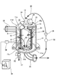
図2は上記濾過器10と連結する配管および電気制御系に示す全体システム図である。上記濾過液取出管16より循環管27を分岐させ、該循環管27を洗浄液供給管13に回転軸受(図示せず)を介して連結している。この循環管27に洗浄用ポンプ28を介設している。また、該洗浄用ポンプ28の上流位置にストレーナ55を介設し、洗浄用ポンプ28のメンテナンスを最小限としている。
上記洗浄用ポンプ28の駆動制御するため、濾過器10内の処理液溜め部Bの圧力P1と濾過液溜め部Aの圧力P2との差圧を検出する差圧センサー30を設けている。該差圧センサー30の検出信号を制御器31に送信し、P1>P2になると共に、P1>P2が設定時間T1継続すると、制御器31よりポンプ28を駆動させる制御を行い、洗浄を開始するようにしている。
【0025】
なお、P1>P2で且つ予め設定した閾値よりもP1が大となった場合にポンプ28を駆動させる設定としてもよい。さらには、上記差圧センサー30による圧力検出に因らず、タイマーを用いて、設定時間間隔でポンプ28を駆動させて洗浄を間欠的に行わせる設定としてもよい。さらにまた、タイマーと差圧センサーとを併用してもよい。
【0026】
さらに、上記循環管27には、ストレーナ55の上流側で上水道水供給管50と分岐させ、この分岐位置に流路切替弁51を介設している。即ち、濾過液の使用量が多くなった場合には、洗浄用に使用せず、洗浄は上水道水で行えるようにしている。
【0027】
上記ドレン管17に流路開閉弁32を介設し、これら開閉弁32を上記制御器31で開閉制御し、ポンプ28が駆動する洗浄期間は開閉弁32を開くようにし、ポンプ28の非駆動時には開閉弁32を閉じるようにしている。
上記処理液導入管18は処理液槽35に開閉弁33、ポンプ36を介して連通させている。ポンプ36と開閉弁33の間よりバイパス管39を設け、該バイパス管39に開閉弁56を介設すると共に先端を濾過液取出管16に連通させている。濾過液取出管16にはバイパス管39との連通位置より上流に開閉弁40を設けている。上記濾過液取出管16とバイパス管39との合流位置より、特殊洗浄用ノズル37の供給管38に連通している。
【0028】
上記フィルター12をメンテナンス等により濾過器10より取り外す際には、開閉弁33、40を閉じる一方、バイパス管39の開閉弁56を開き、処理液槽35の液体をバイパス管39を通して供給管38に供給している。
【0029】
上記構成からなる装置において、図5に示すように、フィルター12に捕捉された異物がフィルターのウエッジワイヤー20の隙間20cに付着し、フィルター12に詰まりが発生すると、上記P1の圧力が大となって、P1>P2となる。この関係が差圧センサー30で検出され、制御器31に送信される、かつ、設定時間T1が経過すると、洗浄用ポンプ28が駆動し、洗浄液供給管13に洗浄液を高圧で供給する。なお、洗浄用ポンプ28の吐出圧は予め一定に設定しておいても良いし、上記差圧センサーによる検出値に応じて吐出圧を自動制御してもよい。即ち、差圧が大でフィルター12の詰まりは大きい時は吐出圧を大として洗浄水をより高圧として、洗浄能力を高めてもよい。
【0030】
洗浄用ポンプ28の駆動と同時に、制御器31により回転用モータ25を駆動してノズルヘッダー14を回転させる。また、同時に、ドレン管17の開閉弁32を開く。
【0031】
洗浄液供給管13にはポンプ28より所要圧に加圧された濾過液Q3が供給され、フィルター12の中空部の濾過液溜め部A内で回転するノズルヘッダー14を通してノズルチップ23より図6(A)に示すように、フィルター12の内周面に向かって、濾過方向と逆方向に、高圧洗浄水となる濾過液Q3が噴射され、フィルター12は洗浄される。この洗浄時に、図6(B)に示すように、フィルター12のウエッジワイヤー20の表面に付着すると共に隙間20cに堆積している異物Sをフィルター12の外周側の処理液溜め部Bへと吹き飛ばす。
処理液溜め部Bへと吹き飛ばされた異物Sが混入した洗浄後の洗浄液はケース本体11の底壁11aに設けたドレン口よりドレン管17を通して排出される。
【0032】
制御器31により予め設定している期間、上記洗浄を行い、期間経過後、ポンプ28を停止し、開閉弁32を閉じる。
なお、上記フィルターの洗浄時にも、処理液槽35から濾過器10への処理液の導入を継続スルト共に、濾過液の取り出しを継続し、ラインを止めないようにしている。
【0033】
上記のように、フィルター12の詰まりを差圧センサー30で検出し、自動的にフィルター12の洗浄を開始するため、常に、濾過作用を定常に保つことが出来る。かつ、洗浄時にフィルターをケースより取り出したり、移動させる必要がないと共に作業員による手作業での洗浄を不要とでき、さらに、洗浄水として濾過液を循環利用するため、節水効果を上げることができる。
【0034】
なお、第1実施形態ではケース本体内の中央にフィルター12を1個配置しているが、ケース本体を大容積とし、フィルターを間隔をあけて複数個配置し、各フィルター内部に回転駆動されるノズルヘッダーを配置し、該ノズルヘッダーに取り付けたノズルチップよりフィルターに高圧洗浄液を噴射してフィルターを逆洗浄する構成とすることが好ましい。該構成とすると、多量の処理液を一度に処理することが可能となる。
【0035】
上記フィルター12の中空部の濾過液溜め部Aに配置する洗浄液噴射装置は、図7(A)に示す角ヘッダータイプとしているが、図7(B)に示すように、洗浄液供給管13’を濾過液溜め部Aの下端近傍まで垂下させ、該洗浄液供給管13’に長さ方向に一定間隔をあけ、かつ、180度対向位置にノズルアダプター42を固着し、その先端にノズルチップ23を先端に取り付ける構成としてもよい。さらに、図7(C)に示すように、一方向だけに向いたノズルチップ23を取り付けてもよい。さらにまた、図7(D)に示すように、ノズルチップ23を洗浄液供給管13’に螺旋状に取り付けても良い。
さらに、上記差圧センサー30は濾過液取出管16内の濾過液と、濾過器10内の処理液溜め部Bの処理液との液圧の差圧を検出する構成としても良い。
【0036】
さらに、フィルター12のフィルター材として上記実施形態のようにウエッジワイヤー20を用いると、異物による目詰まりを発生させにくく利点があるが、金属製ワイヤーに代えて、樹脂製としてもよい。さらに、図8(A)に示す金属製あるいは樹脂製のメッシュ材を用いてもよい、さらにまた、図8(B)に示す金属製のパンチングメタルあるいは樹脂製の穴あき板を用いてもよい。
【0037】
図9は第2実施形態を示す。
第2実施形態は第1実施形態と濾過液溜め部と処理液溜め部とを逆とし、フィルター12’の中空部を処理液溜め部B’、フィルター12’の外部を濾過液溜め部A’としている。それに伴い、処理液導入口11e’はケース底壁11a’に設けてフィルタ12’の中空部の処理液溜め部B’に連通させると共に、濾過液取出口11b’を周壁11d’に設けている。また、ドレン排出口11c’を底壁の処理液溜め部B’と連通する位置に設けている。
【0038】
第1実施形態と同様に、濾過後の浄水を循環させると共にポンプで加圧されて高圧洗浄液を噴射する洗浄液供給管13’は、ケース本体11’の周壁11d’の内面に沿って固定している。
一方、ケース内部の中央に配置するフィルター12’の上端面に上蓋12a’を取り付け、該上蓋12a’の中央に支軸50を突設し、該支軸50を蓋15’より突出させ、第1実施形態と同様に、該支軸50を蓋15’に搭載した回転用モータ25’で回転駆動している。
【0039】
また、上記フィルター12’は円筒形状に構成した金属メッシュより形成している。上記洗浄液供給管13’には長さ方向に間隔をあけてフィルター12’側に突出させ、ノズルチップ23’を取り付けている。この洗浄液供給管13’にポンプ28’を駆動して浄水を導入する洗浄時期は、フィルター12’に目詰まりが発生する期間を予測してタイマーで設定し、所要時間経過後は自動的にポンプ28’が駆動すると共にフィルター回転用モータ25’が駆動して洗浄を行うようにしている。他の構成は第1実施形態と同様であるため説明を省略する。
なお、第2実施形態においても、フィルター12’は金属メッシュに限らず、前記した各種形態のフィルターを用いることができる。かつ、洗浄時期もタイマーだけに限定されず、第1実施形態と同様に差圧センサーを用いても良いし、タイマーと差圧センサーを併用してもよい。
【0040】
第2実施形態においては、フィルター12’の中空部の処理液溜め部B’に導入した固体異物が混入された処理液はフィルター12’の内側から外側へと流通して、フィルター12’で異物が捕捉され、濾過液はフィルター12’の外側の濾過液溜め部A’に溜まり、濾過液取出管16’を通して取り出される。
【0041】
フィルター12’に目詰まりが発生する時期となると、タイマーの作動で自動的にポンプ28’が駆動して洗浄液供給管13’に高圧洗浄水を供給してノズルチップ23’よりフィルター12’の外周面に向けて高圧洗浄水を噴射する。同時にフィルター回転用モータ25’が駆動して、フィルター12’が回転する。よって、ノズルチップ23’よりフィルター12’の全外周面に向けて高圧洗浄水を噴射させることができる。
【0042】
噴射された高圧洗浄水はフィルター12’のメッシュに付着した異物をフィルター12’内の処理液溜め部B’に吹き飛ばし、第1実施形態と同様にフィルター12’を逆洗浄する。この処理液溜め部B’内に吹き飛ばされた異物および洗浄液は処理液溜め部B’内の底壁に設けたドレン排出口より排出される。
【0043】
上記第2実施形態においても、ケース本体11’の内部に複数の円筒状フィルター12’を配置し、各フィルター12’に向けて高圧洗浄水を噴射する洗浄液供給管13’をケース内部に配管してもよい。
【0044】
【発明の効果】
以上の説明より明らかなように、本発明によれば、フィルターの洗浄が自動開始でき、全く人手を介さずに全自動化を図ることができる。かつ、フィルターを洗浄する洗浄液として濾過液を循環させて再利用し節水をしていながら、ポンプにより加圧してノズルへと供給しているため、強い力でフィルターに洗浄液を噴射させることができ、フィルターに付着した異物を確実に除去することができ、特に、フィルターとしてウエッジワイヤーを用いると、ノズルからの噴射される洗浄液による異物除去を確実に行うことができる。
さらに、ノズルより洗浄液をフィルターに噴射して洗浄している時も、濾過器への処理液の導入を停止せず、濾過作用を連続させて、濾過液を濾過液取出管へと供給しているため、処理液の濾過器への導入、濾過作用、濾過液の取り出が中断されず、ラインを止めずに、濾過器内のフィルターの自動洗浄を行うことができる。
【0045】
さらに、洗浄液噴射用のノズルはフィルターの全長にわたって配置されると共に、洗浄液供給管あるいはフィルターを回転させるため、フィルターの全周にわたって洗浄液を噴射させ、フィルター全体の洗浄を全く人手を介さずに自動化することができる。特に、洗浄液供給管を回転させる場合には、フィルターは濾過時のままとしておくことができ、フィルターの濾過器からの取り出しや移動、分解等が不要となる等の種々の利点を有するものである。
【図面の簡単な説明】
【図1】 本発明の第1実施形態の一部断面斜視図である。
【図2】 第1実施形態のシステム図である。
【図3】 図1に示す濾過器の断面図でる。
【図4】 フィルターの一部斜視図である
【図5】 フィルターに異物が付着している状態を示す図面である
【図6】 (A)は洗浄時にノズルより洗浄液をフィルターに噴射している状態を示す図面、(B)はフィルターより異物が除去される状態を示す図面である。
【図7】 (A)は第1実施形態の洗浄用ノズルを示し、(B)(C)(D)は変形例を示す図面である。
【図8】 (A)(B)はフィルター材の変形例を示す図面である。
【図9】 第2実施形態の一部断面斜視図である。
【符号の説明】
10 濾過器
11 ケース本体
11b 濾過液取出口
11c ドレン排出口
11e 処理液流入口
12 フィルター
13 洗浄液供給管
14 ノズルヘッダー
15 蓋
16 濾過液取出管
17 ドレン管
18 処理液導入管
20 ウエッジワイヤー
23 ノズルチップ
25 回転用モータ
27 循環管
28 洗浄用ポンプ
30 差圧センサー
31 制御器
A 濾過液溜め部
B 処理液溜め部
Q1 処理液
Q2 濾過液
Q3 高圧洗浄液[0001]
BACKGROUND OF THE INVENTION
The present invention relates to an automatic cleaning device for a filter that filters sewage to obtain purified water. In particular, when the filter is clogged, the high-pressure cleaning water is sprayed using a nozzle to automatically remove foreign substances.
[0002]
[Prior art]
2. Description of the Related Art Conventionally, a filter built in a sewage filter or the like is installed in order to capture foreign matters mixed in the processing liquid, so that the filter is likely to be clogged due to foreign matters adhering thereto. When clogging occurs, it becomes difficult for the treatment liquid to pass through the filter, and the filtering action is significantly reduced. Therefore, it is necessary to clean the filter.
[0003]
In general, workers regularly remove the filter from the filter and use a brush or spatula to rub the surface of the filter to scrape off foreign matter. When rubbing the filter surface, remove foreign matter from the filter eyes (gap). It was difficult to remove by being further subdivided, and there was also a risk of damaging the filter when scraping.
In addition, there are also problems such as complicated attachment / detachment, replacement of consumables, maintenance, and the like.
[0004]
In order to solve the above problems, a reverse cleaning type cleaning method disclosed in Japanese Patent No. 2670831 (Patent Document 1) has recently been used.
The cleaning of the filter by the above reverse cleaning method is to arrange the cleaning liquid pipe outside the filter or in the hollow part of the filter, and spray the cleaning liquid from the nozzle attached to the cleaning liquid pipe in the direction opposite to the filtration direction, The particulate matter adhering to the filter is removed.
[0005]
[Patent Document 1]
Japanese Patent No. 2670831
[0006]
[Problems to be solved by the invention]
The cleaning system disclosed in Patent Document 1 does not disclose how the filter cleaning time is set. Since the processing liquid with a large amount of foreign matter is likely to clog the filter, it is necessary to automatically start cleaning at a necessary time, and it is particularly required to automate the cleaning time of the filter.
Further, in Patent Document 1, it is also disclosed that purified water after filtration is used as the cleaning liquid ejected from the nozzle. However, the pressure of the purified water after filtration often decreases, and the cleaning ability decreases when the pressure of the cleaning liquid decreases. There is also a problem that a stable cleaning effect cannot be obtained.
Although a cleaning apparatus having a reverse cleaning method is disclosed in addition to the above-mentioned Patent Document 1, most have a complicated structure in which the filter is partially cleaned in order to ensure cleaning power, There is also a problem that becomes the cause of failure and the necessity of maintenance increases.
[0007]
The present invention is intended to solve the above-mentioned problems, and when the filter is automatically washed, the washing liquid is used as high-pressure water to enhance the washing ability and perform stable washing, and the filter is divided and moved during washing. It is an object to be able to perform cleaning in the state at the time of cleaning.
[0008]
[Means for Solving the Problems]
In order to solve the above problems, as a first invention, in a case provided with a processing liquid inlet port in which foreign matters are mixed and a filtered filtrate outlet port.With an upper lidA cylindrical filter is accommodated, and a treatment liquid reservoir that communicates with the treatment liquid inlet between the outer surface of the filter and the inner surface of the case, and a filtrate reservoir that communicates with the filtrate outlet is provided inside the filter. In an automatic cleaning device for a filter having a cleaning liquid supply pipe having a nozzle attached to the filtrate reservoir,
The case includes a case main body having a flat bottom wall on a cylindrical peripheral wall, and a lid attached to the upper surface of the case main body,From the upper lid placed on the inner surface of the lidBottom of case bodyWallIn the case body insideInPlace the above filter,
A filtrate outlet connected to the filtrate outlet pipe is opened at the center of the bottom wall of the case body, and the lower end of the filter is disposed on the upper surface of the outer peripheral wall surrounding the outlet of the filtrate. A drain discharge port connected to a drain pipe is provided on the bottom wall of the processing liquid reservoir between the filter and the inner peripheral surface of the case main body, and the upper part of the peripheral wall of the case main body is connected to the processing liquid introduction pipe. A treatment liquid inlet is provided, and the treatment liquid flowing in from the treatment liquid inlet is caused to flow down while swirling along the inner surface of the peripheral wall in the treatment liquid reservoir,
In addition, the lidAnd the upper lidThe cleaning liquid supply pipe is rotatably penetrated, and the filtrate is circulated through the cleaning liquid supply pipe and pressurized with a cleaning pump, and / or a separately prepared cleaning liquid is supplied with the cleaning pump. And pressurizing and supplying the cleaning liquid supply pipe or the filter rotation motor;
The rotation motor and the cleaning pump are driven and controlled by a signal from a differential pressure sensor that detects the differential pressure between the internal and external hydraulic pressures of the filter, or are driven and controlled by a timer, and the cleaning pump is driven by the nozzle. The high-pressure cleaning liquid is sprayed across the entire surface of the filter in the direction opposite to the filtration direction, the foreign matter adhering to the filter and the cleaning liquid are blown off to the treatment liquid reservoir, and the foreign matter-contaminated drain liquid is discharged to the drain pipe through the drain discharge port. There is provided an automatic filter cleaning device characterized in that the filter is configured to be made to have a structure.
[0009]
When the filtrate is circulated and reused, a circulation pipe branched from the filtrate outlet pipe communicated with the filtrate outlet is provided, and the circulation pipe is connected to the washing liquid supply pipe as washing water. The filtrate after filtration is used, and a washing pump is provided in the circulation pipe to supply the filtrate as high-pressure washing water to the washing liquid supply pipe.
Moreover, it is preferable that a strainer is provided at an upstream position of the cleaning pump.
[0010]
In the case of using both the circulating use of the filtrate and the separately prepared cleaning liquid, for example, the use of tap water, the branch pipe is branched from the tap water supply pipe at a position upstream from the pump for cleaning the circulation pipe, Is provided with a flow path switching valve.
If it is the said structure, according to the usage-amount of a filtrate, a tap water can be replenished and used as a washing | cleaning liquid.
[0011]
As described above, in the present invention, the timing for cleaning the filter by spraying the cleaning liquid from the nozzle is automatically set by the signal from the differential pressure sensor for the internal and external liquid pressure of the filter or / and the timer.
When setting with the signal from the differential pressure sensor, if the filter becomes clogged, the liquid pressure of the processing liquid will be higher than that of the filtrate, and it is necessary to start cleaning with the detection signal from the differential pressure sensor. The cleaning can be started automatically at the time. Instead of using this differential pressure sensor, it is also possible to know in advance the time when clogging occurs in advance and to automatically set the cleaning start time using a timer. In either case, the filter can be automatically washed by automatically spraying the cleaning liquid from the nozzle at the time when the filter should be washed, and the good filtering action by the filter can always be maintained stably. .
In addition, the setting of the cleaning time by the timer and the setting of the cleaning time by the signal of the differential pressure sensor are used together to perform regular cleaning by the timer, and when the filter suddenly becomes clogged, the differential pressure sensor detects it. May be cleaned.
[0012]
In particular, in the present invention, the water-saving effect is given by using the filtrate filtered by the filter as the cleaning liquid sprayed from the nozzle. However, in order to enhance the cleaning effect, high-pressure cleaning water is provided through a pump. In this way, when the pump is interposed, the liquid pressure of the cleaning liquid can also be controlled, and the cleaning liquid can be increased in pressure according to the contamination state of the processing liquid, so that the foreign substances adhering to the filter can be reliably removed.
[0013]
Driving means for rotating the cleaning liquid supply pipe or the filter is provided. That is, when the hollow portion of the filter is used as a filtrate reservoir, the cleaning liquid supply pipe suspended from the hollow portion of the filter is rotated to spray the cleaning liquid over the entire inner peripheral surface of the cylindrical filter. On the other hand, when the processing liquid is introduced into the hollow part of the filter to form a processing liquid reservoir, and the outside of the filter is used as a filtrate storage part, a cleaning liquid supply pipe is provided outside the filter to spray the cleaning liquid on the outer surface of the filter. It is preferable to fix the cleaning liquid supply pipe and rotate the filter.
[0014]
As above,The hollow portion of the cylindrical filter is the filtrate reservoir, and the portion surrounded by the case inner peripheral surface and the filter outer peripheral surface is a treatment liquid reservoir.
The cleaning liquid supply pipe has a length extending substantially along the central axis of the cylindrical filter, and nozzles are arranged at intervals in the length direction, and a rotation motor is provided at a portion protruding from the case of the cleaning liquid supply pipe. The rotating motor is driven when the pump is driven to rotate the cleaning liquid supply pipe, and the high pressure cleaning liquid is sprayed around the entire inner surface of the filter.
[0015]
Further, as a second invention, contrary to the above configuration, the hollow portion of the cylindrical filter is used as a treatment liquid reservoir, and a portion surrounded by the case inner peripheral surface and the filter outer peripheral surface is stored as a filtrate storage. An automatic filter cleaning device is provided.
In other words, inside the case with a treatment liquid inlet with foreign matter and a filtered filtrate outlet.With an upper lidA cylindrical filter is accommodated, and the inside of the filter serves as a treatment liquid reservoir that communicates with the treatment liquid inlet, and a filtrate reservoir that communicates between the filter outer surface and the case inner surface with the filtrate outlet. In an automatic cleaning device for a filter having a cleaning liquid supply pipe having a nozzle attached to the filtrate reservoir,
The case includes a case main body having a flat bottom wall on a cylindrical peripheral wall, and a lid attached to the upper surface of the case main body,From the upper lid placed on the inner surface of the lidBottom of case bodyWallIn the case body insideInPlace the above filter,
A processing liquid inlet connected to the processing liquid introduction pipe is opened at the center of the bottom wall of the case body so that the processing liquid flows in in the axial direction of the case, and an outer peripheral bottom wall surrounding the processing liquid inlet A lower end of the filter is disposed on the upper surface, a drain discharge port connected to a drain pipe is provided on the bottom wall sandwiched between the filter and the processing liquid inlet, and the upper part of the peripheral wall surrounding the processing liquid reservoir is Provide a filtrate outlet,
The cleaning liquid supply pipe has a length over the entire length of the cylindrical filter, and is arranged at a predetermined position on the inner surface of the case while disposing nozzles at intervals in the length direction,
A rotation motor is attached to a portion protruding from the case connected to the end face of the filter,
Circulate the filtrate and pressurize and supply it with a cleaning pump, or / and pressurize and supply a separately prepared cleaning liquid with a cleaning pump,
In addition, the cleaning pump and the rotation motor are driven and controlled by a signal from a differential pressure sensor that detects a differential pressure between the internal and external hydraulic pressures of the filter, or are driven and controlled by a timer to rotate the filter, and By driving the cleaning pump, high pressure cleaning liquid is sprayed from the nozzle to the entire outer periphery of the filter, and foreign matter and cleaning liquid adhering to the filter are blown off to the treatment liquid reservoir, and the foreign matter-contaminated drain liquid passes through the drain discharge port. The present invention provides an automatic filter cleaning apparatus characterized by being configured to be discharged into the drain pipe.
[0016]
The drain pipe is the bottom of the treatment liquid reservoir.On the wallIn order to continue to the drain outlet provided, an open / close valve is provided, and the open / close valve is opened only when the cleaning liquid is driven by the pump to discharge the contaminated drain liquid, and the open / close valve is closed during filtration during non-washing. The untreated processing liquid introduced into the processing liquid reservoir is prevented from being discharged through the drain pipe.
[0017]
The filter is configured by a configuration in which wedge wires having a triangular cross section are connected in an annular arrangement in the axial direction, or a cylindrical material made of a mesh material or a punching material.
If the above-mentioned wedge wire is used as the filter material, it can be a filter having a slit over the entire length in the axial direction, and by allowing the gap between adjacent wedge wires to be appropriately dimensioned, it is possible to easily set the allowable filter passage size. Can be set. And since it is a cross-sectional triangle, the contact area with the foreign material at the time of filtration is small, and it is hard to generate | occur | produce clogging with a foreign material. And since the wedge wire which consists of a thick metal rod has rigidity, even if it injects high pressure washing water, a deformation | transformation will not arise.
[0018]
DETAILED DESCRIPTION OF THE INVENTION
Embodiments of the present invention will be described below with reference to the drawings.
1 to 6 show a
[0019]
At the center of the
[0020]
As shown in FIGS. 3 and 4, the
[0021]
The processing liquid passes from the outer peripheral side to the inner peripheral side with respect to the
[0022]
In the filtrate reservoir A of the hollow part of the
At that time, when the cleaning liquid Q3 sprayed from the nozzle tip reaches the
The cleaning liquid Q3 sprayed from the
[0023]
Further, a rotating
[0024]
FIG. 2 is an overall system diagram showing the piping connected to the
In order to control the driving of the
[0025]
In addition, it is good also as a setting which drives the
[0026]
Further, the
[0027]
The
The processing
[0028]
When the
[0029]
In the apparatus configured as described above, as shown in FIG. 5, when the foreign matter captured by the
[0030]
Simultaneously with the driving of the
[0031]
Filtrate Q3 pressurized to a required pressure is supplied from the
The cleaning liquid after cleaning mixed with the foreign matter S blown to the processing liquid reservoir B is discharged through the
[0032]
The cleaning is performed for a period set in advance by the
Even when the filter is washed, the processing liquid is continuously introduced from the
[0033]
As described above, clogging of the
[0034]
In the first embodiment, one
[0035]
The cleaning liquid injection device disposed in the filtrate storage part A of the hollow portion of the
Further, the
[0036]
Further, when the
[0037]
FIG. 9 shows a second embodiment.
In the second embodiment, the filtrate reservoir and the treatment liquid reservoir are reversed from those of the first embodiment, the hollow portion of the filter 12 'is the treatment liquid reservoir B', and the outside of the filter 12 'is the filtrate reservoir A'. It is said. Accordingly, the
[0038]
As in the first embodiment, the cleaning
On the other hand, an
[0039]
The filter 12 'is formed of a metal mesh having a cylindrical shape. The cleaning
In the second embodiment, the filter 12 'is not limited to the metal mesh, and various types of filters described above can be used. Further, the cleaning time is not limited to the timer, and a differential pressure sensor may be used as in the first embodiment, or the timer and the differential pressure sensor may be used in combination.
[0040]
In the second embodiment, the treatment liquid mixed with the solid foreign matter introduced into the treatment liquid reservoir B ′ of the hollow portion of the
[0041]
When clogging occurs in the filter 12 ', the pump 28' is automatically driven by the operation of the timer to supply high-pressure cleaning water to the cleaning liquid supply pipe 13 'and the outer periphery of the filter 12' from the nozzle tip 23 '. Inject high-pressure washing water toward the surface. At the same time, the filter rotating motor 25 'is driven to rotate the filter 12'. Therefore, high-pressure washing water can be sprayed from the
[0042]
The sprayed high-pressure washing water blows off foreign matters adhering to the mesh of the filter 12 'to the treatment liquid reservoir B' in the filter 12 ', and reverse-washes the filter 12' as in the first embodiment. The foreign matter and cleaning liquid blown off into the processing liquid reservoir B 'are discharged from a drain discharge port provided on the bottom wall in the processing liquid reservoir B'.
[0043]
Also in the second embodiment, a plurality of
[0044]
【The invention's effect】
As is clear from the above description, according to the present invention, the filter cleaning can be automatically started, and full automation can be achieved without any manual intervention. And while circulating the filtrate as a cleaning liquid for cleaning the filter and reusing it to save water, it is pressurized by the pump and supplied to the nozzle, so the cleaning liquid can be sprayed to the filter with a strong force, Foreign matter adhering to the filter can be reliably removed. In particular, when a wedge wire is used as the filter, foreign matter can be reliably removed by the cleaning liquid sprayed from the nozzle.
In addition, even when cleaning liquid is sprayed from the nozzle to the filter, the introduction of the processing liquid into the filter is not stopped, the filtration action is continued, and the filtrate is supplied to the filtrate outlet pipe. Therefore, the introduction of the treatment liquid into the filter, the filtering action, and the removal of the filtrate are not interrupted, and the filter in the filter can be automatically washed without stopping the line.
[0045]
Furthermore, the nozzle for cleaning liquid injection is arranged over the entire length of the filter, and the cleaning liquid supply pipe or the filter is rotated, so that the cleaning liquid is sprayed over the entire circumference of the filter and the cleaning of the entire filter is automated without human intervention. be able to. In particular, when the cleaning liquid supply pipe is rotated, the filter can be left at the time of filtration, and has various advantages such as removal, movement, and decomposition of the filter from the filter are unnecessary. .
[Brief description of the drawings]
FIG. 1 is a partial cross-sectional perspective view of a first embodiment of the present invention.
FIG. 2 is a system diagram of the first embodiment.
FIG. 3 is a cross-sectional view of the filter shown in FIG.
FIG. 4 is a partial perspective view of a filter.
FIG. 5 is a drawing showing a state in which foreign matter adheres to the filter.
6A is a view showing a state in which cleaning liquid is sprayed from a nozzle during cleaning, and FIG. 6B is a view showing a state in which foreign matter is removed from the filter.
7A shows the cleaning nozzle according to the first embodiment, and FIGS. 7B, 7C, and 7D show modifications.
FIGS. 8A and 8B are views showing a modification of the filter material. FIGS.
FIG. 9 is a partial cross-sectional perspective view of a second embodiment.
[Explanation of symbols]
10 Filter
11 Case body
11b Filtrate outlet
11c Drain outlet
11e Treatment liquid inlet
12 Filter
13 Cleaning liquid supply pipe
14 Nozzle header
15 lid
16 Filtrate outlet tube
17 Drain pipe
18 Treatment liquid introduction tube
20 Wedge wire
23 Nozzle tip
25 Motor for rotation
27 Circulation pipe
28 Cleaning pump
30 Differential pressure sensor
31 Controller
A Filtrate reservoir
B Treatment liquid reservoir
Q1 treatment liquid
Q2 Filtrate
Q3 High pressure cleaning liquid
Claims (5)
上記ケースは円筒状の周壁に平板状の底壁を備えたケース本体と、該ケース本体の上面に取り付ける蓋を備え、該蓋の内面に配置する上記上蓋からケース本体の底壁までケース本体の内部に上記フィルターを配置し、
上記ケース本体の底壁の中央に上記濾過液取出管と連結した濾過液取出口を開口していると共に、該濾過液取出口を囲む外周の底壁上面に上記フィルターの下端を配置し、該フィルターとケース本体の内周面に挟まれた上記処理液溜め部の底壁にドレン管を連結したドレン排出口を設け、かつ、該ケース本体の周壁の上部に処理液導入管と連結する上記処理液流入口を設け、該処理液流入口から流入する処理液を上記処理液溜め部内を上記周壁の内面に沿って旋回させながら流下させ、
さらに、上記蓋および上記上蓋に上記洗浄液供給管を回転自在に貫通させており、該洗浄液供給管には、上記濾過液を循環させて洗浄用ポンプで加圧して供給し、あるいは/および別に用意した洗浄液を洗浄用ポンプで加圧して供給し、かつ、上記洗浄液供給管あるいは上記フィルターの回転用モータを設け、
上記回転用モータおよび上記洗浄用ポンプを上記フィルターの内外液圧の差圧を検出する差圧センサーからの信号で駆動制御し、あるいはタイマーにより駆動制御し、該洗浄用ポンプの駆動で上記ノズルより高圧洗浄液を濾過方向と逆方向にフィルターの全面にわたって噴射させ、該フィルターに付着した異物と洗浄液を上記処理液溜め部へと吹き飛ばさせ、異物混入ドレン液を上記ドレン排出口を通して上記ドレン管に排出させる構成としていることを特徴とするフィルターの自動洗浄装置。 A cylindrical filter having an upper cover is accommodated in a case having a processing liquid inlet port in which foreign matter is mixed and a filtered filtrate outlet port, and the processing liquid inlet port is provided between the filter outer surface and the case inner surface. Automatic cleaning of a filter having a treatment liquid reservoir connected to the filter and a filtrate reservoir connected to the filtrate outlet, and a cleaning liquid supply pipe having a nozzle attached to the filtrate reservoir. In the device
The case is a case body having a flat bottom wall to the cylindrical wall, a lid to be attached to the upper surface of the case body, the case body at the bottom Kabema of the case body from the upper lid to place the inner surface of the lid inside and placing the filter,
A filtrate outlet connected to the filtrate outlet pipe is opened at the center of the bottom wall of the case body, and the lower end of the filter is disposed on the upper surface of the outer peripheral wall surrounding the outlet of the filtrate. A drain discharge port connected to a drain pipe is provided on the bottom wall of the processing liquid reservoir between the filter and the inner peripheral surface of the case main body, and the upper part of the peripheral wall of the case main body is connected to the processing liquid introduction pipe. A treatment liquid inlet is provided, and the treatment liquid flowing in from the treatment liquid inlet is caused to flow down while swirling along the inner surface of the peripheral wall in the treatment liquid reservoir,
Further, the cleaning liquid supply pipe is rotatably passed through the lid and the upper lid, and the filtrate is circulated through the cleaning liquid supply pipe and supplied with pressure by a cleaning pump, or / and separately prepared. And supplying the cleaning liquid pressurized with a cleaning pump, and provided with a motor for rotating the cleaning liquid supply pipe or the filter,
The rotation motor and the cleaning pump are driven and controlled by a signal from a differential pressure sensor that detects the differential pressure between the internal and external hydraulic pressures of the filter, or are driven and controlled by a timer, and the cleaning pump is driven by the nozzle. The high-pressure cleaning liquid is sprayed across the entire surface of the filter in the direction opposite to the filtration direction, the foreign matter adhering to the filter and the cleaning liquid are blown off to the treatment liquid reservoir, and the foreign-contaminated drain liquid is discharged to the drain pipe through the drain discharge port. A filter automatic cleaning device characterized by being configured to allow
上記ケースは円筒状の周壁に平板状の底壁を備えたケース本体と、該ケース本体の上面に取り付ける蓋を備え、該蓋の内面に配置する上記上蓋からケース本体の底壁までケース本体の内部に上記フィルターを配置し、
上記ケース本体の底壁の中央に上記処理液導入管と連結した処理液流入口を開口してケースの軸線方向に処理液を流入していると共に、該処理液流入口を囲む外周の底壁上面に上記フィルターの下端を配置し、該フィルターと上記処理液流入口に挟まれた底壁にドレン管を連結したドレン排出口を設け、かつ、上記処理液溜め部を囲む周壁の上部に上記濾過液取出口を設け、
上記洗浄液供給管は、上記筒形状のフィルターの全長にわたる長さとし、長さ方向に間隔をあけてノズルを配置すると共に、上記ケース内面の所定位置に固定する一方、
上記フィルターの端面に連結して上記ケース外に突出した部位に回転用モータを付設し、
上記濾過液を循環させて洗浄用ポンプで加圧して供給し、あるいは/および別に用意した洗浄液を洗浄用ポンプで加圧して供給し、
かつ、上記洗浄用ポンプおよび上記回転用モータを上記フィルターの内外液圧の差圧を検出する差圧センサーからの信号で駆動制御し、或いはタイマーにより駆動制御し、上記フィルターを回転させると共に、該洗浄用ポンプの駆動で上記ノズルよりフィルターの外面全周に高圧洗浄液を噴射させ、該フィルターに付着した異物と洗浄液を上記処理液溜め部へと吹き飛ばさせ、異物混入ドレン液を上記ドレン排出口を通して上記ドレン管に排出させる構成としていることを特徴とするフィルターの自動洗浄装置。A processing liquid reservoir that houses a cylindrical filter having an upper lid inside a case having a processing liquid inlet port in which foreign matters are mixed and a filtered filtrate outlet port, and the inside of the filter communicates with the processing liquid inlet port And an automatic cleaning device for a filter having a filtrate reservoir connected between the outer surface of the filter and the inner surface of the case and the filtrate outlet, and a cleaning liquid supply pipe having a nozzle attached to the filtrate reservoir. In
The case is a case body having a flat bottom wall to the cylindrical wall, a lid to be attached to the upper surface of the case body, the case body at the bottom Kabema of the case body from the upper lid to place the inner surface of the lid inside and placing the filter,
A processing liquid inlet connected to the processing liquid introduction pipe is opened at the center of the bottom wall of the case body so that the processing liquid flows in in the axial direction of the case, and an outer peripheral bottom wall surrounding the processing liquid inlet A lower end of the filter is disposed on the upper surface, a drain discharge port connected to a drain pipe is provided on the bottom wall sandwiched between the filter and the processing liquid inlet, and the upper part of the peripheral wall surrounding the processing liquid reservoir is Provide a filtrate outlet,
The cleaning liquid supply pipe has a length over the entire length of the cylindrical filter, and is arranged at a predetermined position on the inner surface of the case while disposing nozzles at intervals in the length direction,
A rotation motor is attached to a portion protruding from the case connected to the end face of the filter,
Circulate the filtrate and pressurize and supply it with a cleaning pump, or / and pressurize and supply a separately prepared cleaning liquid with a cleaning pump,
In addition, the cleaning pump and the rotation motor are driven and controlled by a signal from a differential pressure sensor that detects a differential pressure between the internal and external hydraulic pressures of the filter, or are driven and controlled by a timer to rotate the filter, and By driving the cleaning pump, high pressure cleaning liquid is sprayed from the nozzle to the entire outer periphery of the filter, and foreign matter and cleaning liquid adhering to the filter are blown off to the treatment liquid reservoir, and the foreign matter-contaminated drain liquid passes through the drain discharge port. An automatic filter cleaning apparatus characterized in that the drain pipe is configured to discharge.
Priority Applications (1)
| Application Number | Priority Date | Filing Date | Title |
|---|---|---|---|
| JP2003022650A JP4309143B2 (en) | 2003-01-30 | 2003-01-30 | Automatic filter cleaning device |
Applications Claiming Priority (1)
| Application Number | Priority Date | Filing Date | Title |
|---|---|---|---|
| JP2003022650A JP4309143B2 (en) | 2003-01-30 | 2003-01-30 | Automatic filter cleaning device |
Publications (2)
| Publication Number | Publication Date |
|---|---|
| JP2004230298A JP2004230298A (en) | 2004-08-19 |
| JP4309143B2 true JP4309143B2 (en) | 2009-08-05 |
Family
ID=32951669
Family Applications (1)
| Application Number | Title | Priority Date | Filing Date |
|---|---|---|---|
| JP2003022650A Expired - Lifetime JP4309143B2 (en) | 2003-01-30 | 2003-01-30 | Automatic filter cleaning device |
Country Status (1)
| Country | Link |
|---|---|
| JP (1) | JP4309143B2 (en) |
Cited By (2)
| Publication number | Priority date | Publication date | Assignee | Title |
|---|---|---|---|---|
| KR200489003Y1 (en) * | 2018-10-26 | 2019-04-17 | 최양덕 | self cleaning filter |
| KR20200015238A (en) * | 2018-08-03 | 2020-02-12 | (주)보경종합기술 | Water purification device provided with bypass means |
Families Citing this family (20)
| Publication number | Priority date | Publication date | Assignee | Title |
|---|---|---|---|---|
| WO2008083714A1 (en) * | 2007-01-11 | 2008-07-17 | Taprogge Gmbh | Filter for fluids |
| WO2008096451A1 (en) * | 2007-02-09 | 2008-08-14 | H. Ikeuchi & Co., Ltd. | Filtering apparatus with washing nozzle |
| JP5214504B2 (en) * | 2009-03-16 | 2013-06-19 | 株式会社テイエルブイ | Pressure reducing valve |
| CN102159509A (en) * | 2009-03-30 | 2011-08-17 | 美得华水务株式会社 | Suction filtration/concentration method and suction filtration/concentration device |
| KR101394229B1 (en) * | 2012-08-17 | 2014-05-14 | 주식회사 파나시아 | Multi-cage type ballast water filter equipment having discharge pipe which can be attached and detached |
| KR101394227B1 (en) | 2012-08-17 | 2014-05-27 | 주식회사 파나시아 | Multi―cage type ballast water filter equipment auto―controlling simultaneously back―washing and method thereof |
| KR101381892B1 (en) * | 2012-08-17 | 2014-04-04 | 주식회사 파나시아 | Multi-cage type ballast water filter equipment having the space stored temporarily back-washing water |
| KR101838593B1 (en) * | 2014-03-24 | 2018-04-27 | 주식회사 파나시아 | Multi―cage type ballast water filter equipment auto―controlling simultaneously back―washing and method thereof |
| JP2016028804A (en) * | 2014-07-22 | 2016-03-03 | 株式会社リコー | Fluid filtration device and fluid processing device |
| JP6231451B2 (en) * | 2014-08-04 | 2017-11-15 | 株式会社大気社 | Purification device |
| KR101570438B1 (en) * | 2015-06-25 | 2015-11-19 | 주영림 | Working Fluid Supply System by Using Distilled Water Supply Apparatus with Self-cleaning Filter Function |
| KR101740022B1 (en) | 2016-11-09 | 2017-05-25 | 한국중부발전(주) | Filter clearing apparatus |
| CN107413096A (en) * | 2017-09-05 | 2017-12-01 | 无锡市凡宇水处理机械制造有限公司 | Enter the clear water tanks of water filtration storage by all kinds of means |
| CN107661644A (en) * | 2017-11-08 | 2018-02-06 | 广州市大进工业设备有限公司 | A kind of intelligently filters machine |
| JP7014045B2 (en) * | 2018-05-16 | 2022-02-01 | 株式会社デンソー | Cooling system |
| KR102072648B1 (en) * | 2019-07-10 | 2020-02-03 | 김순성 | Water purifier for agriculture |
| CN114146492B (en) * | 2021-11-30 | 2023-02-24 | 中广核工程有限公司 | Automatic flushing standby system and automatic flushing method |
| CN115814503B (en) * | 2023-02-14 | 2023-04-28 | 广州智达实验室科技有限公司 | Intelligent filtering device based on automation |
| CN116510383B (en) * | 2023-05-05 | 2023-09-26 | 广州极效能源科技有限公司 | Circulating oil filtering equipment with filtering medium and automatic cleaning function |
| KR102593351B1 (en) * | 2023-05-31 | 2023-10-25 | 프리젠트 주식회사 | Filter Faucet Head |
-
2003
- 2003-01-30 JP JP2003022650A patent/JP4309143B2/en not_active Expired - Lifetime
Cited By (3)
| Publication number | Priority date | Publication date | Assignee | Title |
|---|---|---|---|---|
| KR20200015238A (en) * | 2018-08-03 | 2020-02-12 | (주)보경종합기술 | Water purification device provided with bypass means |
| KR102131067B1 (en) * | 2018-08-03 | 2020-07-07 | (주)보경종합기술 | Water purification device provided with bypass means |
| KR200489003Y1 (en) * | 2018-10-26 | 2019-04-17 | 최양덕 | self cleaning filter |
Also Published As
| Publication number | Publication date |
|---|---|
| JP2004230298A (en) | 2004-08-19 |
Similar Documents
| Publication | Publication Date | Title |
|---|---|---|
| JP4309143B2 (en) | Automatic filter cleaning device | |
| US5876612A (en) | Method and apparatus for cleaning filter material in a filter apparatus | |
| US6156213A (en) | Embedded spin-clean cartridge-type water filters | |
| KR100497099B1 (en) | Filtration device, and method of cleaning filter material contained in filtration device | |
| FI90500C (en) | Water clarification equipment for the removal of fines larger than a predetermined size | |
| US9422738B2 (en) | Filter apparatus with filter cleaning arrangement | |
| KR101657028B1 (en) | Rotary disc filter with automatic integrated backwash and chemical cleaning system | |
| JPH11509771A (en) | Backwashing apparatus and method for fluid filter system | |
| US5815544A (en) | Self-cleaning strainer | |
| EP2771292B1 (en) | Water filter | |
| US11648592B2 (en) | System for treating wash waste liquid, adapted for application in a continuous tunnel washing machine in the field of preclinical pharmaceutical research | |
| KR20190011018A (en) | Filtering device having auto-recycling function and filtering system comprising the same | |
| KR20130063563A (en) | Automatic strainer | |
| JP2002263411A (en) | Strainer | |
| KR20170122153A (en) | Rotor filter system with auto-reactivation function | |
| US20060180528A1 (en) | Waste water recovery system | |
| CN101072616A (en) | Filter device and method for purifying polluted liquids | |
| JPH1033912A (en) | Filtering method and apparatus therefor | |
| CN205019814U (en) | Liquid filter | |
| JPH09150016A (en) | Filtration method, filtration apparatus, and filtration system using same | |
| JPH02119904A (en) | Automatic filter device | |
| KR101169954B1 (en) | automatic preprocessor filter | |
| IL272438B2 (en) | Self-cleaning filtering system and method | |
| KR200365421Y1 (en) | A treatment plant of wastewater | |
| AU703286B2 (en) | Apparatus and method for backwashing fluid filter systems |
Legal Events
| Date | Code | Title | Description |
|---|---|---|---|
| A621 | Written request for application examination |
Free format text: JAPANESE INTERMEDIATE CODE: A621 Effective date: 20051104 |
|
| A977 | Report on retrieval |
Free format text: JAPANESE INTERMEDIATE CODE: A971007 Effective date: 20071018 |
|
| A131 | Notification of reasons for refusal |
Free format text: JAPANESE INTERMEDIATE CODE: A131 Effective date: 20071030 |
|
| A521 | Request for written amendment filed |
Free format text: JAPANESE INTERMEDIATE CODE: A523 Effective date: 20071228 |
|
| A131 | Notification of reasons for refusal |
Free format text: JAPANESE INTERMEDIATE CODE: A131 Effective date: 20081014 |
|
| A521 | Request for written amendment filed |
Free format text: JAPANESE INTERMEDIATE CODE: A523 Effective date: 20081211 |
|
| TRDD | Decision of grant or rejection written | ||
| A01 | Written decision to grant a patent or to grant a registration (utility model) |
Free format text: JAPANESE INTERMEDIATE CODE: A01 Effective date: 20090407 |
|
| A01 | Written decision to grant a patent or to grant a registration (utility model) |
Free format text: JAPANESE INTERMEDIATE CODE: A01 |
|
| A61 | First payment of annual fees (during grant procedure) |
Free format text: JAPANESE INTERMEDIATE CODE: A61 Effective date: 20090507 |
|
| R150 | Certificate of patent or registration of utility model |
Free format text: JAPANESE INTERMEDIATE CODE: R150 Ref document number: 4309143 Country of ref document: JP Free format text: JAPANESE INTERMEDIATE CODE: R150 |
|
| FPAY | Renewal fee payment (event date is renewal date of database) |
Free format text: PAYMENT UNTIL: 20120515 Year of fee payment: 3 |
|
| FPAY | Renewal fee payment (event date is renewal date of database) |
Free format text: PAYMENT UNTIL: 20130515 Year of fee payment: 4 |
|
| R250 | Receipt of annual fees |
Free format text: JAPANESE INTERMEDIATE CODE: R250 |
|
| FPAY | Renewal fee payment (event date is renewal date of database) |
Free format text: PAYMENT UNTIL: 20180515 Year of fee payment: 9 |
|
| R250 | Receipt of annual fees |
Free format text: JAPANESE INTERMEDIATE CODE: R250 |
|
| R250 | Receipt of annual fees |
Free format text: JAPANESE INTERMEDIATE CODE: R250 |
|
| R250 | Receipt of annual fees |
Free format text: JAPANESE INTERMEDIATE CODE: R250 |
|
| R250 | Receipt of annual fees |
Free format text: JAPANESE INTERMEDIATE CODE: R250 |
|
| R250 | Receipt of annual fees |
Free format text: JAPANESE INTERMEDIATE CODE: R250 |
|
| R250 | Receipt of annual fees |
Free format text: JAPANESE INTERMEDIATE CODE: R250 |
|
| EXPY | Cancellation because of completion of term |