JP4308702B2 - Exhaust purification equipment - Google Patents
Exhaust purification equipment Download PDFInfo
- Publication number
- JP4308702B2 JP4308702B2 JP2004121510A JP2004121510A JP4308702B2 JP 4308702 B2 JP4308702 B2 JP 4308702B2 JP 2004121510 A JP2004121510 A JP 2004121510A JP 2004121510 A JP2004121510 A JP 2004121510A JP 4308702 B2 JP4308702 B2 JP 4308702B2
- Authority
- JP
- Japan
- Prior art keywords
- temperature
- catalyst
- forced regeneration
- oxidation catalyst
- catalyst deterioration
- Prior art date
- Legal status (The legal status is an assumption and is not a legal conclusion. Google has not performed a legal analysis and makes no representation as to the accuracy of the status listed.)
- Expired - Fee Related
Links
Images


Classifications
-
- Y—GENERAL TAGGING OF NEW TECHNOLOGICAL DEVELOPMENTS; GENERAL TAGGING OF CROSS-SECTIONAL TECHNOLOGIES SPANNING OVER SEVERAL SECTIONS OF THE IPC; TECHNICAL SUBJECTS COVERED BY FORMER USPC CROSS-REFERENCE ART COLLECTIONS [XRACs] AND DIGESTS
- Y02—TECHNOLOGIES OR APPLICATIONS FOR MITIGATION OR ADAPTATION AGAINST CLIMATE CHANGE
- Y02T—CLIMATE CHANGE MITIGATION TECHNOLOGIES RELATED TO TRANSPORTATION
- Y02T10/00—Road transport of goods or passengers
- Y02T10/10—Internal combustion engine [ICE] based vehicles
- Y02T10/40—Engine management systems
Description
この発明は、ディーゼルエンジンの排気中に含まれるPM(Particulate Matter:粒子状物質)を除去処理するための排気浄化装置に関する。 The present invention relates to an exhaust emission control device for removing PM (Particulate Matter) contained in exhaust gas of a diesel engine.
近年、ディーゼルエンジンの排気中に含まれるPMを低減する排気浄化装置として、上流側から酸化触媒(DOC)とPMを捕集するフィルタ(DPF)が並んで設けられた連続再生式ディーゼルパティキュレートフィルタ(以下、CR−DPFと称する)の開発が注目されている。このCR−DPFは、エンジンの排気中に含まれるPMをフィルタに捕集しつつ、その捕集PMを燃焼除去するものである。酸化触媒はフィルタの上流側に設けられ、酸化触媒において排気中に含まれるNOをNO2に変換することによりフィルタにおける捕集PMの酸化反応を促すとともに、酸化触媒における酸化反応熱によりフィルタを加熱する機能を果たす。 In recent years, as an exhaust purification device for reducing PM contained in exhaust of a diesel engine, a continuous regeneration type diesel particulate filter provided with an oxidation catalyst (DOC) and a filter (DPF) for collecting PM from the upstream side. The development of (hereinafter referred to as CR-DPF) has attracted attention. This CR-DPF collects PM contained in the exhaust of the engine in a filter and burns and removes the collected PM. The oxidation catalyst is provided on the upstream side of the filter. In the oxidation catalyst, NO contained in the exhaust gas is converted to NO 2 to promote the oxidation reaction of the collected PM in the filter, and the filter is heated by the oxidation reaction heat in the oxidation catalyst. Fulfills the function of
しかし、酸化触媒はその触媒の性質上、高温にさらされると上記機能が低下する劣化を起こし、CR−DPFシステムの性能低下を招く。このため、酸化触媒の劣化度を精度よく判定してたポスト噴射等にしたり、システムの性能維持に役立てたいという要求がある。 However, due to the nature of the catalyst, the oxidation catalyst undergoes deterioration in which the above functions are reduced when exposed to high temperatures, leading to a reduction in the performance of the CR-DPF system. For this reason, there is a demand for post-injection that accurately determines the degree of deterioration of the oxidation catalyst, or for maintaining the performance of the system.
従来、触媒の劣化を検出するものとして、例えば特許文献1に開示された排気浄化装置は、酸化触媒を通過した排気の酸素濃度を検出するO2センサを備え、このO2センサの出力値に応じて酸化触媒の劣化度を判定するようになっている。
Conventionally, as an apparatus for detecting deterioration of a catalyst, for example, an exhaust gas purification device disclosed in
特許文献2に開示された排気浄化装置は、酸化触媒の上流側と下流側にて排気温度を検出する排気温度センサを備え、この排気温度センサの出力値とエンジンの運転状態に応じて可燃物(HC)の単位流量当たりの発熱量を推定し、推定された発熱量が設定値以下と判定される回数をカウントし、カウントされた回数が所定回数以上になったときに、酸化触媒が劣化状態にあるものと判定するようになっている。
しかしながら、特許文献1に開示された排気浄化装置は、酸素濃度を高精度で検出するO2センサを必要とするため、製品のコストアップを招き、酸化触媒の劣化度を判定する制御が複雑化するという問題点があった。
However, since the exhaust gas purification device disclosed in
特許文献2に開示された排気浄化装置は、可燃物の単位流量当たりの発熱量を精度よく推定することが難しく、酸化触媒が劣化状態を精度よく判定できないという問題点があった。
The exhaust emission control device disclosed in
本発明は上記の問題点に鑑みてなされたものであり、連続再生式ディーゼルパティキュレートフィルタに設けられる酸化触媒の触媒劣化状態を精度よく判定できる排気浄化装置を提供することを目的とする。 The present invention has been made in view of the above-described problems, and an object of the present invention is to provide an exhaust purification device that can accurately determine the catalyst deterioration state of an oxidation catalyst provided in a continuously regenerating diesel particulate filter.
本発明では、エンジンの排出ガス成分を触媒作用により酸化させる酸化触媒と、この酸化触媒の下流側に介装され排気中に含まれるPMを捕集するフィルタとを備えるエンジンの排気浄化装置において、燃料噴射時期を遅らせたポスト噴射等にてフィルタの強制再生を行う強制再生手段と、酸化触媒の温度を検出する温度検出手段と、酸化触媒の検出温度が予め設定された触媒劣化判定温度を超える過熱温度を算出する過熱温度算出手段と、運転時間に対して検出された過熱温度が高まるのに応じて重み付けをした超過時間を積算する超過時間積算手段と、積算された超過時間に応じて触媒劣化度を判定する触媒劣化判定手段とを備える。 In the present invention, in an engine exhaust gas purification apparatus comprising an oxidation catalyst that oxidizes engine exhaust gas components by catalytic action, and a filter that is disposed downstream of the oxidation catalyst and collects PM contained in exhaust gas, Forced regeneration means for forcibly regenerating the filter by post-injection etc. with delayed fuel injection timing, temperature detection means for detecting the temperature of the oxidation catalyst, and the detected temperature of the oxidation catalyst exceeds a preset catalyst deterioration determination temperature An overheating temperature calculating means for calculating an overheating temperature, an excess time integrating means for integrating an excess time weighted according to an increase in the detected overheating temperature with respect to the operation time, and a catalyst according to the accumulated excess time Catalyst deterioration determining means for determining the degree of deterioration.
本発明によると、酸化触媒の温度が所定の触媒劣化判定温度を超えて上昇する過熱温度に応じて触媒機能が低下する現象に対応して、運転時間に対して過熱温度に応じて重み付けをした超過時間を積算し、積算された超過時間に応じて触媒劣化度を判定する構成としたため、空燃比センサ等を用いることなく、酸化触媒の劣化状態を精度よく判定できる。 According to the present invention, the operating time is weighted according to the superheating temperature in response to a phenomenon in which the catalyst function decreases in response to the superheating temperature at which the temperature of the oxidation catalyst rises above a predetermined catalyst deterioration determination temperature. Since the excess time is integrated and the catalyst deterioration degree is determined according to the integrated excess time, the deterioration state of the oxidation catalyst can be accurately determined without using an air-fuel ratio sensor or the like.
本発明の実施形態を添付図面に基づいて説明する。 Embodiments of the present invention will be described with reference to the accompanying drawings.
図1において、10はディーゼルエンジンであり、コモンレール式燃料噴射装置(図示せず)を備える。エンジン10の吸気通路11にターボ過給機12のコンプレッサ12a、インタクーラ13、吸気絞り弁14が介装される。エンジン10の排気通路15にターボ過給機12のタービン12b、排気絞り弁16、CR−DPF17が介装される。図1において、22はターボ過給機12のタービン12bを迂回するターボバイパス通路に設けられる開閉バルブ、21はEGR(排気還流)装置のEGRバルブである。
In FIG. 1,
CR−DPF17は、酸化触媒26とDPF25とから構成される。排気通路15には酸化触媒26の下流側にDPF25が介装される。
The CR-
DPF(フィルタ)25は、ハニカム構造体に形成され、その格子状に区画される流路(セル)の入口と出口が交互に目封じされる。つまり、入口の目封じされる流路と出口の目封じされる流路とが交互に隣接され、これらを区画する多孔質の隔壁が排気の通過を許容するようになっている。この例においては、隔壁に捕集されるPMの燃焼可能な着火温度を低めに設定するため、触媒(プラチナ等)付きフィルタが採用される。 The DPF (filter) 25 is formed in a honeycomb structure, and the inlets and outlets of flow paths (cells) partitioned in a lattice shape are alternately sealed. That is, the flow path sealed at the inlet and the flow path sealed at the outlet are alternately adjacent to each other, and the porous partition walls that partition these allow passage of the exhaust gas. In this example, a filter with a catalyst (platinum or the like) is employed in order to set the ignition temperature at which PM collected in the partition walls can be combusted to a low level.
酸化触媒26は、触媒と、この触媒を担持するハニカム構造体とを備え、ハニカム構造体の格子状に区画される流路を通過する排気に含まれる主にHC(炭化水素)を酸化処理するものであり、その反応熱により触媒温度が上昇して堆積PMの燃焼を促進するのである。
The
コモンレール式燃料噴射装置は、コモンレールに燃料を蓄圧する高圧ポンプと、このコモンレールを介して導かれる加圧燃料を各気筒に噴射する燃料噴射ノズルとを備え、この燃料噴射ノズルの作動がコントロールユニット20によって制御される。コントロールユニット20の制御に必要な検出手段として、エンジン回転数Neを検出する回転センサ(クランク角センサを兼ねる)およびエンジン負荷qを検出する負荷センサのほか、CR−DPF17の入口圧力と出口圧力との差圧を検出する差圧センサ30、酸化触媒26の出口温度(DPF25の入口温度)を検出する温度センサ31aとDPF25の出口温度を検出する温度センサ31b、吸気流量を検出するエアフローセンサ32等が設けられる。
The common rail fuel injection device includes a high pressure pump for accumulating fuel in the common rail, and a fuel injection nozzle for injecting pressurized fuel guided through the common rail into each cylinder. The operation of the fuel injection nozzle is controlled by the
酸化触媒26の予熱手段については、EGRバルブ21、吸気絞り弁14または排気絞り弁16、ターボバイパスの開閉バルブ22がエンジン10の排気温度を積極的に高める制御に利用される。ターボ過給機12が可変ノズル式の場合、可変ノズルを触媒の予熱手段として制御することも考えられる。
As for the preheating means of the
DPF25の強制再生が必要な時期の判定については、DPF25のPM堆積量算出値(推定量)が所定値以上のときにDPF25の強制再生時期を判定する判定手段と、DPF25前後の差圧(またはCR−DPF17の入口圧力)が所定値以上のときにDPF25の強制再生時期を判定する判定手段と、PM堆積量算出値に基づく強制再生の完了から計測される運転時間(または運転距離)が強制再生用に設定のインターバルに達するとその間に強制再生の履歴がないときにDPF25の強制再生時期を判定する判定手段と、運転時間(または運転距離または強制再生の回数)がPM堆積量算出値を定期的に初期化する0リセット強制再生用のインターバルに達すると強制再生を判定する第二判定手段とが設定される。
Regarding the determination of the time when the forced regeneration of the
DPF25の強制再生時期はこのような複数の異なる方法に基づいて判定される。コントロールユニット20は、これら何れかの判定を受けると、そのときの判定方法に対応する強制再生モードとしてPM堆積量算出値に応じた強制再生温度および強制再生時間を設定する。
The forced regeneration time of the
コントロールユニット20は、燃料の噴射制御を行うのにあたり、通常の制御マップと、強制再生用の昇温マップが格納されている。通常運転時にエンジン回転数Neとエンジン負荷qとから通常の制御マップに基づいて噴射ノズルへの燃料噴射信号(噴射量の指令および噴射時期の指令)を決定する。DPF25の強制再生が必要な時期を判定すると、通常の制御マップから強制再生用の昇温マップに切換え、CR−DPF17の雰囲気温度が所定値(例えば、230℃)を下回るときは、触媒の予熱手段を駆動するほか、必要があれば昇温マップに基づいて燃料のメイン噴射に続いて燃焼可能なタイミングでアフタ噴射を行う燃料噴射信号を決定する一方、CR−DPF17の雰囲気温度が所定値以上のときは、昇温マップに基づいてメイン噴射の後から圧縮上死点より遅れるタイミングでポスト噴射を行う燃料噴射信号を決定する。
The
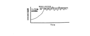
コントロールユニット20は、酸化触媒26が所定の触媒劣化判定温度(例えば700℃)を超えないようにエンジン10の運転を制御する。これは、例えば強制再生用の昇温制御マップに基づいてメイン噴射の後から圧縮上死点より遅れるタイミングでポスト噴射をする燃料噴射制御が行われるDPF25の強制再生時等に、温度センサ31aによって検出される酸化触媒26のDOC出口温度が所定値を超えて上昇すると、昇温制御マップから通常の制御マップへと切換え、ポスト噴射を行わない通常の燃料噴射制御を行うようになっている(図7参照)。
The
しかし、ポスト噴射が行われるDPF25の強制再生時等に何らかの原因で酸化触媒26が触媒劣化判定温度を超える状態で運転される可能性がある。その場合、酸化触媒26はその触媒機能が低下する劣化を起こし、CR−DPF17の性能低下を招く。
However, there is a possibility that the
酸化触媒26の触媒機能が低下する劣化度合いは、酸化触媒26が触媒劣化判定温度を超える超過温度が高いほど大きくなる。例えば、酸化触媒26が例えば700℃を維持して運転される場合は運転時間が600分を超えると触媒機能の劣化度が所定の限界値に達する一方、酸化触媒26が例えば1000℃を維持して運転される場合は運転時間が例えば1分を超えると触媒劣化度が所定の限界値に達する。
The degree of deterioration in which the catalytic function of the
本発明は、上記した酸化触媒26の温度に応じて触媒機能が低下する現象に着目してなされたものであり、コントロールユニット20は酸化触媒26の検出温度が予め設定された触媒劣化判定温度を超える過熱温度を算出する過熱温度算出手段と、運転時間に対して検出された過熱温度が高まるのに応じて重み付けをした超過時間を積算する超過時間積算手段と、積算された超過時間に応じて触媒劣化度を判定する触媒劣化判定手段とを備え、触媒劣化度を精度よく判定するものである。
The present invention has been made by paying attention to the phenomenon that the catalytic function is lowered in accordance with the temperature of the
図2は触媒劣化度を判定するマップの概念図である。このマップは横軸に酸化触媒26のDOC出口温度(過熱温度)とし、縦軸を各DOC出口温度毎に積算される運転時間として、DOC出口温度に応じた限界運転時間が設定されている。この限界運転時間はDOC出口温度が高い程短くなるように設定されている。DOC出口温度が例えば700℃では限界運転時間が600分となり、DOC出口温度が例えば1000℃では限界運転時間が例えば1分となっている。
FIG. 2 is a conceptual diagram of a map for determining the degree of catalyst deterioration. In this map, the limit operating time corresponding to the DOC outlet temperature is set with the horizontal axis representing the DOC outlet temperature (superheated temperature) of the
図3は触媒劣化度を判定する過程を示す説明図である。これについて説明すると、ポスト噴射が行われるDPF25の強制再生時等に何らかの原因で酸化触媒26が所定の触媒劣化温度(例えば700℃)を超える状態で運転されることが4回あった場合、1〜3回目までの運転時では各DOC出口温度毎に積算される運転時間が限界値を超えないが、1〜4回目までの運転時では各DOC出口温度毎に積算される運転時間が限界値を超える。したがって4回目の運転時に触媒機能が限界値を超えて劣化したものと判定される。
FIG. 3 is an explanatory diagram showing a process of determining the degree of catalyst deterioration. Explaining this, when the
本実施形態では、温度検出手段として酸化触媒26の下流側のDOC出口温度を検出する温度センサ31aを設け、コントロールユニット20は温度センサ31aの検出値に応じて酸化触媒26の触媒機能の劣化を判定する。
In the present embodiment, a
図4のフローチャートはDPF25の強制再生を行う制御ルーチンの例を示しており、これはコントロールユニット20において一定周期毎に実行される。
The flowchart of FIG. 4 shows an example of a control routine for forcibly regenerating the
これについて説明すると、まず、ステップ1にて、前回のエンジン運転状況をメモリより読み込む。
This will be described. First, in
続くステップ2にて、システムのハード面及びソフト面にて何らかの異常が生じたか否かを判定する。ここで異常が生じたと判定された場合、ステップ9に進んで警告ランプ等を点灯して運転者に異常を知らせる。
In
図5のフローチャートは酸化触媒の触媒機能の劣化を判定するルーチンを示して
おり、図4のフローチャートにおけるステップ2にて行われるシステムの異常を判定するルーチンの一つとして行われる。
The flowchart of FIG. 5 shows a routine for determining the deterioration of the catalytic function of the oxidation catalyst, and is performed as one of the routines for determining the system abnormality performed in
これについて説明すると、まず、ステップ11にて、前回までのエンジン運転時に記憶されたデータをメモリより読み込む。続くステップ12にて、酸化触媒26のDOC出口温度が触媒劣化判定温度を超えるか否かを判定する。
This will be described. First, in
ここでDOC出口温度が触媒劣化判定温度を超えたと判定された場合、ステップ13に進み、DOC出口温度が触媒劣化判定温度を超えた運転時の回数をカウントする。 When it is determined that the DOC outlet temperature has exceeded the catalyst deterioration determination temperature, the process proceeds to step 13 and the number of times of operation in which the DOC outlet temperature has exceeded the catalyst deterioration determination temperature is counted.
続くステップ14に進んで、DOC出口温度が触媒劣化判定温度を超えた過熱温度を算出し、運転時間に対してこの過熱温度が高まるのに応じて重み付けをした超過時間を積算する。 Then, the process proceeds to step 14 where an overheat temperature at which the DOC outlet temperature exceeds the catalyst deterioration determination temperature is calculated, and an excess time weighted according to the increase in the overheat temperature with respect to the operation time is integrated.
続くステップ15に進んで、積算された超過時間が設定値を超えたか否かを判定する。 Proceeding to step 15, it is determined whether or not the accumulated excess time exceeds the set value.
ここで、積算された超過時間が設定値を超えたことが判定された場合、ステップ16に進んで、警告ランプ等を点灯して運転者に異常を知らせる。 Here, if it is determined that the accumulated excess time has exceeded the set value, the process proceeds to step 16 to turn on a warning lamp or the like to notify the driver of the abnormality.
異常が生じていないと判定された場合、ステップ3に進んで、PM堆積量算出値を算出する。ここでは、このPM堆積量算出値は予め設定されたマップに基づきエンジン10の回転数等の運転状態に応じてPM排出量を算出し、このPM排出量から加速度補正等の各補正を行い、さらに温度センサ31aによって検出される排気温度に応じて算出された自己再生量を差し引いて求められる。
When it is determined that no abnormality has occurred, the process proceeds to step 3 to calculate a PM accumulation amount calculation value. Here, this PM accumulation amount calculation value is calculated based on a preset map according to the operating state such as the rotation speed of the
続くステップ4に進んで、強制再生が必要な時期に達したか否かを判定する。ここでは、PM堆積量算出値(推定値)が閾値を超えるか、走行距離や走行時間が閾値を超えるか、あるいは排気圧力(CR−DPF17の前後差圧)が閾値を超えるなどの強制再生が必要な時期を判定する。 Then, the process proceeds to step 4 to determine whether or not the time when forced regeneration is necessary has been reached. Here, forced regeneration is performed such that the PM accumulation amount calculated value (estimated value) exceeds the threshold, the travel distance or travel time exceeds the threshold, or the exhaust pressure (the differential pressure across the CR-DPF 17) exceeds the threshold. Determine when it is needed.
ここで強制再生が必要な時期に達したと判定された場合、ステップ5に進んで通常の制御マップに基づいて燃料噴射制御を行う捕集モードから、強制再生用の昇温マップに基づいて燃料噴射制御を行う強制再生モードに移行し、DPF25の強制再生が行われる。
If it is determined that the time required for forced regeneration has been reached, the routine proceeds to step 5 where the fuel is controlled based on the temperature increase map for forced regeneration from the collection mode in which fuel injection control is performed based on the normal control map. The forced regeneration mode in which the injection control is performed is entered, and the forced regeneration of the
こうして強制再生モードに移行すると、ステップ6に進んで、強制再生時間が閾値を超えるか、あるいはPM堆積量算出値が閾値より少なくなったことが判定されるまでDPF25の強制再生が行われる。
When the forced regeneration mode is thus entered, the routine proceeds to step 6 where the forced regeneration of the
ステップ7にてイグニッションスイッチがOFFになったエンジン停止時に、ステップ8に進んでシステム終了時におけるエンジン運転状況をメモリに保存し、本ルーチンを終了する。
When the engine is stopped when the ignition switch is turned off in
以上のように、酸化触媒26の温度が触媒劣化判定温度を超えて上昇する過熱温度に応じて触媒機能が低下する現象に対応して、運転時間に対して過熱温度に応じて重み付けをした超過時間を積算し、積算された超過時間に応じて触媒劣化度を判定する構成としたため、酸化触媒26の触媒劣化状態を精度よく判定できる。
As described above, the operating time is overweighted according to the superheat temperature in response to the phenomenon that the catalyst function is lowered according to the superheat temperature where the temperature of the
酸化触媒26のDOC出口温度は、酸化触媒26を通過した排気温度であり、酸化触媒26における触媒の活性化状態を反映しているため、酸化触媒26の触媒劣化状態を精度よく判定できる。
Since the DOC outlet temperature of the
次に他の実施形態を図6を参照して説明する。コントロールユニット20は酸化触媒26の検出温度が触媒劣化判定温度を超える運転条件を判定し、DPF25の強制再生時のポスト噴射量を補正する構成としても良い。
Next, another embodiment will be described with reference to FIG. The
図6はこの制御内容を示す説明図である。これについて説明すると、コントロールユニット20は、DPF25の強制再生時にエンジン回転数Neとアクセル開度(エンジン負荷q)とから強制再生用の昇温制御マップに基づいてメイン噴射の後から圧縮上死点より大幅に遅れるタイミングでポスト噴射を行う。エンジン回転数Neとアクセル開度に応じてポスト噴射量が増減するのに伴って、酸化触媒26のDOC出口温度が変化し、ポスト噴射量が過大となる(1)(2)の運転条件にて酸化触媒26のDOC出口温度が触媒劣化判定温度を超えて上昇している。これに対応してコントロールユニット20は、酸化触媒26の温度が触媒劣化判定温度を超える運転条件を判定し、判定された運転条件に基づいて酸化触媒26が過熱される原因となる強制再生用の昇温制御マップに設定されたポスト噴射量を特定でき、このポスト噴射量を補正することにより、酸化触媒26が過熱されて劣化が進むことを防止できる。
FIG. 6 is an explanatory diagram showing the contents of this control. Explaining this, the
次に他の実施形態を図7を参照して説明する。コントロールユニット20は酸化触媒26の検出温度が触媒劣化判定温度を超えることを判定して通常の制御マップと強制再生用の昇温制御マップの切換えを行うマップ切換温度を補正する構成としても良い。
Next, another embodiment will be described with reference to FIG. The
図7はこの制御内容を示す説明図である。これについて説明すると、コントロールユニット20は強制再生用の昇温制御マップに基づいてポスト噴射をする燃料噴射制御が行われるDPF25の強制再生時等に、温度センサ31aによって検出される酸化触媒26のDOC出口温度が所定のマップ切換温度を超えて上昇すると、通常の制御マップに切換え、ポスト噴射を行わない通常の燃料噴射制御を行うようになっている。マップ切換温度の設定値が高すぎると、酸化触媒26が触媒劣化判定温度を頻繁に超える可能性がある。
FIG. 7 is an explanatory diagram showing the contents of this control. Explaining this, the
これに対応して、コントロールユニット20は検出される酸化触媒26の温度が触媒劣化判定温度を超える頻度を算出し、この頻度が所定値より高い場合にマップ切換温度を低く補正することにより、酸化触媒26が過熱されて劣化が進むことを防止できる。
In response to this, the
他の実施形態として、DPF25の出口温度を検出する温度センサ31bの検出信号に応じてDPF25に担持される触媒劣化度を判定する構成としても良い。この場合、酸化触媒26の触媒劣化度を判定する制御と同様に、検出されるDPF25の温度が触媒劣化判定温度を超える過熱温度を算出し、運転時間に対して検出された過熱温度が高まるのに応じて重み付けをした超過時間を積算し、積算された超過時間に応じて触媒劣化度を判定する構成とする。
As another embodiment, the degree of deterioration of the catalyst carried on the
他の実施形態として、触媒劣化判定手段によって求められた酸化触媒26の触媒劣化度に応じて触媒劣化係数を求め(図2参照)、この触媒劣化係数に応じてPM堆積量算出値を補正する構成としても良い。
As another embodiment, a catalyst deterioration coefficient is obtained according to the degree of catalyst deterioration of the
PM堆積量算出値は予め設定されたマップに基づきエンジン10の回転数等の運転状態に応じてPM排出量を算出し、このPM排出量から加速度補正等の各補正を行い、さらに温度センサ31aによって検出される排気温度に応じて算出された自己再生量を差し引いて求められる。酸化触媒26の触媒劣化度、DPF25に担持される触媒劣化度が高まるのに応じて自己再生量が少なくなるように補正することにより、PM堆積量算出値の精度を高められる。
The calculated PM accumulation amount is calculated based on a preset map according to the operating state such as the rotational speed of the
また、酸化触媒26の温度検出手段として酸化触媒26の床温度を検出する床温度センサを設け、コントロールユニット20はこの床温度センサの検出値に応じて酸化触媒26の触媒機能の劣化を判定する構成としても良い。
Further, a bed temperature sensor for detecting the bed temperature of the
本発明は上記の実施形態に限定されずに、その技術的な思想の範囲内において種々の変更がなしうることは明白である。 The present invention is not limited to the above-described embodiment, and it is obvious that various modifications can be made within the scope of the technical idea.
本発明の排気浄化装置は、ディーゼルエンジンの排気中に含まれるPMを連続再生式ディーゼルパティキュレートフィルタを介して除去処理するものに利用できる。 The exhaust emission control device of the present invention can be used for removing PM contained in exhaust gas from a diesel engine through a continuous regeneration type diesel particulate filter.
10 エンジン
15 排気通路
17 CR−DPF
19 燃料噴射装置
20 コントロールユニット
25 DPF(フィルタ)
26 酸化触媒
31〜35 温度センサ
10
19
26 Oxidation catalyst 31-35 Temperature sensor
Claims (4)
前記エンジンの燃料噴射時期を遅らせたポスト噴射等にてフィルタの強制再生を行う強制再生手段と、前記酸化触媒の温度を検出する温度検出手段と、前記酸化触媒の検出温度が予め設定された触媒劣化判定温度を超える過熱温度を算出する過熱温度算出手段と、運転時間に対して検出された過熱温度が高まるのに応じて重み付けをした超過時間を積算する超過時間積算手段と、積算された超過時間に応じて触媒劣化度を判定する触媒劣化判定手段とを備えたことを特徴とする排気浄化装置。 In an exhaust emission control device comprising an oxidation catalyst that oxidizes exhaust gas components of an engine by catalytic action, and a filter that is interposed downstream of the oxidation catalyst and collects PM contained in exhaust gas,
A forced regeneration means for forcibly regenerating the filter by post-injection or the like in which the fuel injection timing of the engine is delayed, a temperature detection means for detecting the temperature of the oxidation catalyst, and a catalyst in which the detection temperature of the oxidation catalyst is set in advance An overheating temperature calculating means for calculating an overheating temperature exceeding the deterioration judgment temperature, an overtime integrating means for adding an excess time weighted according to an increase in the detected overheating temperature with respect to the operation time, and an accumulated excess An exhaust gas purification apparatus comprising catalyst deterioration determination means for determining the degree of catalyst deterioration according to time.
Priority Applications (1)
| Application Number | Priority Date | Filing Date | Title |
|---|---|---|---|
| JP2004121510A JP4308702B2 (en) | 2004-04-16 | 2004-04-16 | Exhaust purification equipment |
Applications Claiming Priority (1)
| Application Number | Priority Date | Filing Date | Title |
|---|---|---|---|
| JP2004121510A JP4308702B2 (en) | 2004-04-16 | 2004-04-16 | Exhaust purification equipment |
Publications (2)
| Publication Number | Publication Date |
|---|---|
| JP2005307745A JP2005307745A (en) | 2005-11-04 |
| JP4308702B2 true JP4308702B2 (en) | 2009-08-05 |
Family
ID=35436815
Family Applications (1)
| Application Number | Title | Priority Date | Filing Date |
|---|---|---|---|
| JP2004121510A Expired - Fee Related JP4308702B2 (en) | 2004-04-16 | 2004-04-16 | Exhaust purification equipment |
Country Status (1)
| Country | Link |
|---|---|
| JP (1) | JP4308702B2 (en) |
Families Citing this family (13)
| Publication number | Priority date | Publication date | Assignee | Title |
|---|---|---|---|---|
| KR100774757B1 (en) * | 2006-03-03 | 2007-11-08 | 현대자동차주식회사 | Regeneration apparatus and the method of diesel's filter system |
| JP4530081B2 (en) | 2008-07-25 | 2010-08-25 | トヨタ自動車株式会社 | Catalyst deterioration diagnosis apparatus and catalyst deterioration diagnosis method for internal combustion engine |
| JP5093617B2 (en) * | 2009-02-18 | 2012-12-12 | 株式会社デンソー | Exhaust gas purification device for internal combustion engine |
| US8407985B2 (en) * | 2009-07-28 | 2013-04-02 | International Engine Intellectual Property Company, Llc | Method of monitoring hydrocarbon levels in a diesel particulate filter |
| US8806928B2 (en) | 2010-04-30 | 2014-08-19 | Toyota Jidosha Kabushiki Kaisha | Catalyst deterioration detection apparatus and catalyst deterioration detection method for internal combustion engine |
| KR101619184B1 (en) * | 2010-11-03 | 2016-05-10 | 현대자동차 주식회사 | System for desulfurization of oxidation catalyst and method thereof |
| JP2013068185A (en) * | 2011-09-26 | 2013-04-18 | Kubota Corp | Diesel engine |
| JP5468106B2 (en) * | 2012-06-08 | 2014-04-09 | ヤンマー株式会社 | Engine equipment |
| JP6213118B2 (en) * | 2013-10-04 | 2017-10-18 | いすゞ自動車株式会社 | Diagnostic equipment |
| JP6183659B2 (en) * | 2014-05-27 | 2017-08-23 | 株式会社豊田自動織機 | Exhaust gas purification device |
| JP2016070097A (en) * | 2014-09-26 | 2016-05-09 | ヤンマー株式会社 | Exhaust emission control device |
| CN114738091A (en) * | 2022-03-23 | 2022-07-12 | 潍柴动力股份有限公司 | DOC control method, automobile post-processing device and storage medium |
| CN115163267B (en) * | 2022-08-26 | 2023-11-17 | 潍柴动力股份有限公司 | DOC diagnosis method and aftertreatment system |
-
2004
- 2004-04-16 JP JP2004121510A patent/JP4308702B2/en not_active Expired - Fee Related
Also Published As
| Publication number | Publication date |
|---|---|
| JP2005307745A (en) | 2005-11-04 |
Similar Documents
| Publication | Publication Date | Title |
|---|---|---|
| US8181449B2 (en) | Control method of exhaust gas purification system and exhaust gas purification system | |
| JP2002303123A (en) | Exhaust emission control device | |
| WO2016104774A1 (en) | EXHAUST PURIFICATION SYSTEM AND METHOD FOR RESTORING NOx PURIFICATION CAPACITY | |
| JP2006029239A (en) | Exhaust emission control filter overheat prevention device | |
| JP2008031854A (en) | Exhaust emission control device for internal combustion engine | |
| JP4308702B2 (en) | Exhaust purification equipment | |
| JP4544011B2 (en) | Internal combustion engine exhaust purification system | |
| JP4267414B2 (en) | Catalyst control device for internal combustion engine | |
| JP4150308B2 (en) | Exhaust purification device | |
| JP4320586B2 (en) | Exhaust gas purification device for internal combustion engine | |
| WO2016152896A1 (en) | Exhaust purification device and control method for same | |
| JP4986667B2 (en) | Exhaust purification device | |
| JP4239765B2 (en) | Exhaust purification catalyst control method and exhaust purification catalyst control apparatus for internal combustion engine | |
| JP4314089B2 (en) | Internal combustion engine catalyst control device and catalyst deterioration determination device | |
| JP4008867B2 (en) | Exhaust purification equipment | |
| JP4185882B2 (en) | Exhaust purification device | |
| JP4635582B2 (en) | Exhaust purification device | |
| JP2005307746A (en) | Exhaust emission control device | |
| JP6183659B2 (en) | Exhaust gas purification device | |
| JP2005273653A (en) | Deterioration diagnosis device for filter | |
| JP4070687B2 (en) | Exhaust purification device | |
| JP5751198B2 (en) | Exhaust gas purification device for internal combustion engine | |
| JP2005307878A (en) | Exhaust emission control device | |
| JP2005307744A (en) | Exhaust emission control device | |
| JP4081419B2 (en) | Exhaust purification device |
Legal Events
| Date | Code | Title | Description |
|---|---|---|---|
| A621 | Written request for application examination |
Free format text: JAPANESE INTERMEDIATE CODE: A621 Effective date: 20070322 |
|
| A977 | Report on retrieval |
Free format text: JAPANESE INTERMEDIATE CODE: A971007 Effective date: 20090123 |
|
| TRDD | Decision of grant or rejection written | ||
| A01 | Written decision to grant a patent or to grant a registration (utility model) |
Free format text: JAPANESE INTERMEDIATE CODE: A01 Effective date: 20090414 |
|
| A01 | Written decision to grant a patent or to grant a registration (utility model) |
Free format text: JAPANESE INTERMEDIATE CODE: A01 |
|
| A61 | First payment of annual fees (during grant procedure) |
Free format text: JAPANESE INTERMEDIATE CODE: A61 Effective date: 20090501 |
|
| R150 | Certificate of patent or registration of utility model |
Free format text: JAPANESE INTERMEDIATE CODE: R150 |
|
| FPAY | Renewal fee payment (event date is renewal date of database) |
Free format text: PAYMENT UNTIL: 20120515 Year of fee payment: 3 |
|
| FPAY | Renewal fee payment (event date is renewal date of database) |
Free format text: PAYMENT UNTIL: 20120515 Year of fee payment: 3 |
|
| S533 | Written request for registration of change of name |
Free format text: JAPANESE INTERMEDIATE CODE: R313533 |
|
| FPAY | Renewal fee payment (event date is renewal date of database) |
Free format text: PAYMENT UNTIL: 20120515 Year of fee payment: 3 |
|
| R350 | Written notification of registration of transfer |
Free format text: JAPANESE INTERMEDIATE CODE: R350 |
|
| LAPS | Cancellation because of no payment of annual fees |