JP4307740B2 - Time tracking method and equipment - Google Patents
Time tracking method and equipment Download PDFInfo
- Publication number
- JP4307740B2 JP4307740B2 JP2000597906A JP2000597906A JP4307740B2 JP 4307740 B2 JP4307740 B2 JP 4307740B2 JP 2000597906 A JP2000597906 A JP 2000597906A JP 2000597906 A JP2000597906 A JP 2000597906A JP 4307740 B2 JP4307740 B2 JP 4307740B2
- Authority
- JP
- Japan
- Prior art keywords
- instance
- late
- energy
- initial
- estimate
- Prior art date
- Legal status (The legal status is an assumption and is not a legal conclusion. Google has not performed a legal analysis and makes no representation as to the accuracy of the status listed.)
- Expired - Lifetime
Links
Images


Classifications
-
- H—ELECTRICITY
- H04—ELECTRIC COMMUNICATION TECHNIQUE
- H04B—TRANSMISSION
- H04B1/00—Details of transmission systems, not covered by a single one of groups H04B3/00 - H04B13/00; Details of transmission systems not characterised by the medium used for transmission
- H04B1/06—Receivers
-
- H—ELECTRICITY
- H04—ELECTRIC COMMUNICATION TECHNIQUE
- H04B—TRANSMISSION
- H04B1/00—Details of transmission systems, not covered by a single one of groups H04B3/00 - H04B13/00; Details of transmission systems not characterised by the medium used for transmission
- H04B1/69—Spread spectrum techniques
- H04B1/707—Spread spectrum techniques using direct sequence modulation
- H04B1/7073—Synchronisation aspects
- H04B1/7085—Synchronisation aspects using a code tracking loop, e.g. a delay-locked loop
Landscapes
- Engineering & Computer Science (AREA)
- Computer Networks & Wireless Communication (AREA)
- Signal Processing (AREA)
- Mobile Radio Communication Systems (AREA)
- Radio Relay Systems (AREA)
- Manufacture, Treatment Of Glass Fibers (AREA)
- Radio Transmission System (AREA)
- Absorbent Articles And Supports Therefor (AREA)
- Circuits Of Receivers In General (AREA)
- Burglar Alarm Systems (AREA)
- Treatments Of Macromolecular Shaped Articles (AREA)
- Processing Of Meat And Fish (AREA)
- Radar Systems Or Details Thereof (AREA)
- Synchronisation In Digital Transmission Systems (AREA)
- Crystals, And After-Treatments Of Crystals (AREA)
Abstract
Description
【0001】
【発明の属する技術分野】
この発明は通信システムに関する。もっと特定すると、この発明は無線(ワイヤレス)通信システムにおける時間追跡(タイムトラッキング)に関する。
【0002】
【従来の技術】
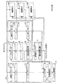
図1は地上無線通信システム10の実施形態の例示である。図1は3つの遠隔ユニット12A,12B,12Cと2つの基地局14とを示す。現実には、典型的な無線通信システムはもっと数多くの遠隔ユニットと基地局とを有することができる。図1では、遠隔ユニット12Aは自動車内に置かれた移動電話ユニットとして示されている。図1はまた可搬形のコンピュータ遠隔ユニット12Bと、固定位置の遠隔ユニット12Cであって無線ローカルループとか計器読取りシステムで見られるようなユニットを示している。最も一般的な実施形態では、遠隔ユニットは何らかの形式の通信ユニットとなる。例えば、遠隔ユニットは手持ちのパーソナル通信ユニットとか、パーソナルデータアシスタントのようなポータブルデータユニットとか、計器読取り装置のような固定位置のデータユニットであることが可能である。図1は基地局14から遠隔ユニット12へ向けたフォワード(前送り)リンク信号18と、遠隔ユニット12から基地局14へ向けたリパース(逆送り)リンク信号20とを示している。
【0003】
一般的な無線通信システムで図1に示したようなものでは、若干の基地局が複数のセクタ(区分)を有している。複数セクタの基地局は、複数の独立した送りと受けとのアンテナとともに独立した処理回路を備えている。ここで論ずる原理は複数セクタの基地局の各セクタと、単一セクタの独立した基地局とに等しく適用する。次降の記述では、したがって、用語“基地局(ベースステーション)”は複数セクタの基地局のある1つのセクタか、単一セクタの基地局か、あるいは複数セクタの基地局かのいずれかを指すものと想定してよい。
【0004】
コード分割多重アクセス(CDMA)システムでは、遠隔ユニットはシステム内の全基地局との通信用に共通の周波数帯域を使用する。共通の周波数帯の使用はフレキシビリティ(隔通性)を増して、システムに大きな利点を与える。例えば、共通周波数帯の使用は、遠隔ユニットが複数の基地局からの通信を同時に受領できるようにするとともに、複数の基地局による受信のために信号を送ることができるようにする。遠隔ユニットはスプレッドスペクトラム(スペクトル拡散)CDMA波形性質の使用を介して各種基地局から同時に受領した信号を弁別して別個に受けることができる。同じように、基地局は複数の遠隔ユニットからの信号を弁別して別個に受けることができる。CDMA技術を多重アクセス通信システムで使用することはUS Pat.No.4,901,307、名称“SPREAD SPECTRUM MULTIPLE ACCESS COMMUNICATION SYSTEM USING SATELLITE OR TERRESTRIAL REPEATERS”本願と同一出願人で、ここで参照に組入れるもの、に開示されている。CDMA技術を多重アクセス通信システムで使用することは、さらにUS Pat.No.5,103,459、名称“SYSTEM AND METHOD FOR GENERATING SIGNAL WAVEFORMS IN A CDMA CELLULAR TELEPHONE SYSTEM”本願と同一出願人で、ここで参照に組入れるもの、にも開示されている。
【0005】
CDMA通信技術は狭帯域変調技術について数多くの利点を与えている。とくに、地上チャンネルは多経路(マルチパス)信号の生成による特殊の問題をもたらすのであるが、これはCDMA技術の使用を介して克服することができる。例えば、基地局受信機では、共通遠隔ユニット信号からの別個の多経路インスタンスが、各種遠隔ユニットからの信号間の弁別で使用されているのと同じようなCDMA技術を用いて弁別されて、別個に受けることができる。
【0006】
地上チャンネルでは、多経路は環境内にある妨害物である樹木、建物、車、人物などからの信号の反射によって作られる。一般に、地上チャンネルは多経路を作り出す構造の相対的な動きが原因して多経路チャンネルを時間変動させる。例えばある理想的なインパルスが多経路チャンネル上で送られるとすると、パルスの流れ(ストリーム)が受領される。時間的に変動する多経路チャンネルでは、受領したパルスの流れは、時間的な位置、振幅及び位置でその理由的なインパルスが送られた時間の関数として変化する。
【0007】
図2は基地局に到達した単一の遠隔ユニットからの信号インスタンスの組の例を示している。たて軸はdB目盛で受領した電力(パワー)を表わす、横軸は伝送経路遅延が原因して基地局に到達したインスタンスの遅延を表わしている。(図示していないが)紙面に入って行く軸は時間区分(セグメント)を表わしている。紙面の共通面内にある各信号インスタンスは共通の時間に到達したのであるが異なる時間に遠隔ユニットにより送られたものである。共通面では右に向う方のピークが、左に向うピークよりも遠隔ユニットによってもっと初期の時間に送られた信号インスタンスを表わしている。例えば、一番左のピーク20は一番最新に送られた信号インスタンスに対応している。各信号ピーク20〜30は異なる経路を通って来た信号に対応し、したがって異なる時間遅延と異なる位相及び振幅応答とを示している。
【0008】
6つの異なる信号スパイクとしてピーク20〜30により表わされているものは厳しい多経路環境の代表的なものである。一般的な市街地環境は使用可能なインスタンスを作ることが少ない。システムのノイズフロア(雑音レベル)は低い方のエネルギーレベルを有するディップとピークとによって表わされる。
【0009】
各多経路ピークは時間の関数として振幅が変ることに注意されたい。その様子は各多経路ピーク20〜30の平坦ではないリッジ(山の背部分)によって示されている。図示のような限定された時間では、多経路ピーク20〜30の振幅に大きな変化は見られない。しかし、時間範囲をもっと拡張すると、多経路ピークは振幅で消えて、新しい経路が時間の進行で作り出される。このピークはまたもっと初期あるいはもっと後期の時間に経路距離の変化とともに滑り動くことができて、その原因は基地局のカバーする領域内にあるオブジェクトの移動とされる。
【0010】
地上環境に加えて、複数の信号インスタンスはまた衛星システムの使用によってももたらすことができる。例えば、グローバルスター(GlobalStar)システムでは、遠隔ユニットは地上基地局ではなく、一連の衛星を介して通信する。この衛星は約2時間で地球を周る軌道をとる。その軌道を通る衛星の動きは遠隔ユニットと衛星との間の経路距離が時間で変るようにさせる。加えて、ある衛星が遠隔ユニットの範囲外を移動するときは、一方の衛星から他方の衛星へのソフトなハンドオフが実行される。ソフトなハンドオフの際には、遠隔ユニットは複数の衛星からの信号を復調する。これら複数の信号インスタンスは地上システムで多経路信号インスタンスと同じやり方で組合せができる。しかし1つ違う点は、信号インスタンスが地上環境では約0〜500マイクロ秒だけ互にオフセットする傾向にあるが、2つの衛星を介して受領した信号インスタンスは0〜20ミリ秒台で互にオフセットする傾向にあることである。
【0011】
地上と衛星の両方のシステムでは使用できない信号インスタンスが他の源(ソース)から生ずることができる。フェーディングの効果を克服するために、例えば、しばしば複数のダイバシティ受信機が使用される。さらに加えて、複数の信号インスタンスが共通基地局のセクタ間のよりソフトなハンドオフの際に作り出される。
【0012】
図3は先行技術のレーキ(rake)受信機の構成図である。図3に示したレーキ受信機はNの復調素子10A〜100Nを備えている。復調素子100Aは図3では詳細に示されていて、また復調素子100B〜100Nに復調素子100Aと同じやり方で構成されると仮定することができる。到来する信号サンプルは復調素子100A〜100Nの各々の入力に接続されている。復調素子100Aの内部には、デスプレッダ(拡散解除器)102が到来信号サンプルを対応する遠隔ユニットで信号をスプレッド(拡散)するために使用したスプレッド用コードと相関をとる。デスプレッダ102の出力は高速Hadamrd(アダマール)変換器(FHT)104に接続される。FHT104はデスプレッドサンプルを可能性のあるシンボル値の組(a set of possible symbol values)の各々1ケと相関をとる。例えば、一実施形態では、システムは電話工業会および電子工業会(TIA/EIA)インターリム規格で通常IS−95と呼ばれているもの(すなわち“Mobile Station-Base Station Compatibility standard For Dual-Mode Wideband Spread Spectrum Cellulat System”と称するTIA/EIA/IS−95)に従って動作する。この規格の内容はそっくりここで参照として組入れることとする。このようなシステムでは、6データビットの群(グループ)が64の直交ウォルシ(Walsh)シンボルの1つに写像される。FHT104はデスプレッドサンプルを64直交ウォルシシンボルと相関をとる。FHT104は一組の異なる電圧レベルを作り、この電圧レベルの1つは可能性のあるシンボル値の各々に対応している。
【0013】
FHT104の出力はエネルギー判断ブロック106に接続されていて、そこでは可能性のあるシンボル値の各々について対応するエネルギー値を判断する。エネルギー判断ブロック106の出力は多経路組合せ器(コンバイナ)110に接続されている。加えて、復調素子100B〜100Nのエネルギー出力値もまた多経路コンバイナ110の入力に接続されている。多経路コンバイナ110は各復調素子100A〜100Nにより出力されたエネルギー値をシンボルベースであるシンボルについて組合せて、エネルギー値の組合せた組を決め、この1つのエネルギー値が可能性のあるシンボル値の各々に対応するものとする。
【0014】
多経路コンバイナ110の出力は最大値検出器112に接続される。最大値検出器112はエネルギー値の組合せた組に基づいて最もありそうな送られたデータ値を判断する。例えば、一実施形態では、最大値検出器112はUS Pat.No.5,442,627、名称“Non-Coherent Receiver Employing a Dual-Maxima Metric Generation Process”本願出願人と同一により動作するもので、この文献をそのままここで参照に組入れる。最大値検出器112の出力はディジタル処理回路に接続されて、そこでさらにディジタル処理が実行される。
【0015】
上述したように、各復調素子100A〜100Nは指定されている信号インスタンスを時間的に追跡する。これをするために、復調素子100Aは正規の時間的オフセットよりも早い方の(初期の)時間オフセットと遅い方の(後期の)時間オフセットで到来する信号を復調する。初期と後期のプロセスのエネルギー結果を比較することにより、現在の時間的推定の精度が通信での周知の原理によって判断できる。図3に示したように、初期デスプレッダ110Aは到来する信号サンプルを、デスプレッダ102により使用された時間オフセットから約半分チップ(chip)だけ進んだ時間オフセットでデスプレッドする。同じように後期デスプレッダ110Bは到来する信号サンプルを、デスプレッダ102により使用された時間オフセットから約半分だけ遅れた時間オフセットでデスプレッドする。初期デスプレッダ110Aと後期デスプレッダ110Bとによる電圧レベル出力は一時的にバッファ112Aと112Bとにそれぞれ記憶される。
【0016】
図3に示すように、エネルギー判断ブロック106の出力はまた最大値検出器108に接続されていて、そこではエネルギー判断ブロック106の出力に基づいて最もありそうな送られたデータ値を判断する。シンボルデカバリング(カバー解除用)ブロック114Aは、バッファ112A内に記憶されたデスプレッドサンプルを最もありそうな送られたデータ値に対応するシンボルと相関をとる。例えば、一実施形態では、ウォルシシンボルで最もありそうな送られたデータ値に対応しているものが記憶されたサンプルと相関がとられ、そのやり方は到来信号サンプルが初期デスプレッダ110A内部でスプレッド用コードと相関をとられたのと同じやり方である。同じやり方で、シンボルデカバリングブロック114Bはバッファ112B内に記憶されたデスプレッドサンプルを最もありそうな送られたデータ値に対応するシンボルと相関をとる。シンボルデカバリングブロック114Aと114Bとはそれぞれ初期エネルギー値と後期エネルギー値とを作る。
【0017】
初期及び後期エネルギー値はゲート及び比較ブロック116に記憶される。もし最もありそうな送られたデータ値で最大値検出器112で選ばれたものが最大値検出器108によって生成されたデータ値と同じであるとすると、ブロック116は初期及び後期エネルギーレベルを比較する。通信理論の周知の原理によると、もし2つの値が等しいとすると、適切な時間オフセットがデスプレッダ102によって使用されている。しかももし一方の値が他方よりも大きいとすると、デスプレッダ102により使用された時間オフセットは理想的な時間オフセットからはずれた(オフセットした)ものである。時間追跡器(タイムトラッカ)118はゲート及び比較ブロック116により出力されたエネルギー値を累積して、デスプレッダ102による使用のために更新された時間オフセット値を決める。加えて時間追跡器118の時間オフセット出力は一般にシステム制御器120に向けて送られて、そこでは復調素子割当てアルゴリズムを実行する。
【0018】
最大値検出器112により生成されたデータ値が、最大値検出器108により生成されたデータ値とは異なっているとすると、最大値検出器108は誤差を生じたと仮定される。この仮定は通信理論の周知の原理に基づくものであり、いくつかの復調素子によって作られたエネルギーレベルを組合せることによって、最もありそうな送られたデータ値についてのもっと正確な判断がされることになるという理論である。この理由により、平均して、最大値検出器112は最大値検出器108よりもより正確な送られたデータについての推定を作る。したがって、最大値検出器108によって生成されたデータ値が最大値検出器112により生成された値と同じでないとすると、対応する初期及び後期エネルギー値は誤差を含んだデータ値を用いて判断されたものと思われ、したがって有効なデータを表わしていない。この理由により、ゲート及び比較ブロック116はこれらの値を無視して、時間追跡器118にこれらの値を送らない。
【0019】
レーキ受信機、復調器及び時間追跡に関する追加の情報はU.S. Patent No.5,654,979、名称“Cell Site Demodulation Architecture for a Spread Spectrum Multiple Access Communication”;U.S. Patent No.5,644,591 、名称“Method and Apparatus for Performing Search Acquisition in a CDMA Communications system”;U.S. Patent No.5,561,618、名称“Method and Apparatus for Performing a Fast Hadamard Transform”;U.S. Patent No.5,490,165、名称“Demodulation Element Assignment in a System Capable of Receiving Multiple Signals”;U.S. Patent No.5,805,648、名称“Method and Apparatus for Performing Search Acquisition in a CDMA Communication System”いずれも本願同一出願人に見ることができ、ここではそのすべてを参照に組入れる。
【0020】
【発明が解決しょうとする課題】
このような動作での1つの欠点は有効でない時間追跡データの実質的な量が増えて、そこでゲート作用プロセスによって無視されることである。例えば、復調素子の誤差率が個々に80%という高いものであったとしても、組合せた信号の誤差率は10%といった低いものとすることができ、したがって現実味のある通信チャンネルを提供する。したがって、その復調素子の誤差率が約80%であるとすると、シンボルデカバリィブロック114A,114Bにより計算されたエネルギー値の5個のうちのほぼ4が無効であり、したがって、ゲートプロセスによって無視され時間追跡器118によっては使用されない。このような状態では、時間追跡器は利用可能なエネルギーの約20%だけに基づいて動作をする。このような動作は時間追跡プロセスを不必要に遅らせ、また時間追跡プロセスの精度を劣化させる。
【0021】
デスプレッダ102により使用される時間オフセットが理想的なオフセットからずれているときは、エネルギー判断ブロック106により出力されるエネルギーが減らされる。図4Aは信号を復調するために使用される時間オフセットの関数として、受領したエネルギーを示すグラフである。図4Aでは、たて軸はレーキ受信機により検出されたエネルギーを表わし、横軸は信号を復調するためにレーキ受信機により使用される時間オフセットを表わす。レーキ受信機が信号を理想的な同期状態で理想的な時間的整列(オンタイムアラインメント、ぴたりあった整列)t0 で復調するときは、レーキ受信機は図4A上のデータ点122で示したように信号から得られる最大エネルギーを検出する。もしレーキ受信機が遠隔ユニット信号を復調するのに理想的な時間的整列t0 から後の時間整列tl までの時間オフセットδt (図ではsT )だけ遅れたタイミングを使用するとすると、このレーキ受信機は図4A上のデータ点124で示す少くなったエネルギーを検出する。同じように、もしレーキ受信機が遠隔ユニット信号を復調するのに、理想的な時間的整列t0 から前の時間整列te までの時間オフセットδt (図ではsT )だけ進んでいるタイミングを使用するとすると、レーキ受信機は図4Aのデータ点123で示す少くなったエネルギーを検出する。初期(先)と後期(後)との整列が同じ量だけ時間的な整列からずれていて、しかもこの時間的整列が理想のものであるとすればその限りでは初期と後期との整列で検出されるエネルギーは同じである。
【0022】
図4Bは図4Aと同じような図であるが、時間的整列t0 ′が理想的タイミングから僅かな遅れをもつようにゆがんでいる。このオフセットが原因してデータ点126で検出されるエネルギー量はデータ点122における理想の場合に検出されるよりも少いことに留意したい。レーキ受信機が信号を復調するのをデータ点127で示すように、図4Bにおける初期時間整列te ′で、時間的整列t0 ′よりも初期に時間オフセットδt (図ではsT )ですると、レーキ受信機は図4Aのデータ点62,64よりも大きなエネルギーを検出する。同じように、レーキ受信機が遠隔ユニット信号を復調するのをデータ点128で示したように後期時間整列tl ′で時間的整列t0 ′から時間オフセットδt (図ではsT )だけ遅れたオフセットですると、レーキ受信機は図4Aで示したデータ点62と64とまた図4Bのデータ点(27とよりも少いエネルギーを検出する。レーキ受信機によって初期時間整列と後期時間整列とにより検出されたエネルギーを比較することによって、時間的整列が理想的な整列かどうか判断することが可能である。初期及び後期整列が同じエネルギーレベルをもたらせば、レーキ受信機は正確な時間整列で信号を検出していそうである。もし初期整列で検出されたエネルギーレベルが後期整列で検出されたエネルギーレベルよりも著しく大きいとすると、レーキ受信機は理想からは遅れている整列で信号を検出しているもののようである。もし後期整列で検出されたエネルギーレベルが初期整列で検出されたエネルギーレベルよりも著しく大きいとすると、レーキ受信機は理想からは進んでいる整列で信号を検出しているもののようである。
【0023】
エネルギーの減少は多経路コンバイナ110により作られる全エネルギーにおける対応した減少を作り出す。したがって、低い方の全エネルギーは最大値検出器ブロック112により実行されるデータ値判断プロセスの精度に対応した減少をもたらし、それにより、受信機の全体の性能を低下させる。加えて、エネルギーの減少は強い信号インスタンスに対するよりも弱い信号インスタンスについての時間追跡の正確さを減退させ、その結果、さらに弱い信号インスタンスにより作られる使用可能なエネルギーを減らすことになる。
【0024】
そうであるから、もっと正確なシステムと、時間追跡(タイムトラッキング)の方法についての技術が長い間求められてきたのである。
【0025】
【課題を解決するための手段】
到来信号を時間追跡するために、受信機は信号の第1のインスタンスを復調して、その信号の可能とされるデータ値の組に対応しているエネルギー値についての第1の組を作る。受信機はまた可能とされるデータ値の組に対応しているエネルギー値の第2の組を作るためにその信号の第2のインスタンスも復調する。受信機はこのエネルギー値の第1と第2との組を組合せてエネルギー値の組合せた組を決める。受信機はこの組合せたエネルギー値の組に基づいて送られたデータ値として最もありそうな(最尤の)データ値についての第1の推定を判断して決める。受信機は第1の推定に対応しているシンボルを用いて第1のインスタンスのデスプレッドサンプルの初期組をデカバーして第1の初期エネルギー値を作る。受信機は第1の推定に対応しているシンボルを用いて第1のインスタンスのデスプレッドサンプルの後期組をデカバーして第1の後期エネルギー値を作る。最後に、受信機は第1の初期エネルギー値と第1の後期エネルギー値とに基づいて第1のインスタンスの時間オフセットを判断する。
【0026】
この発明による動作は時間追跡プロセスへのエネルギー入力を増加する。増加されたエネルギーは時間追跡プロセスの精度と速度とを増す。時間追跡プロセスの性能を高めることによって、以前は適切な時間追跡にとって弱すぎるとされていた信号インスタンスが、今では正確に時間追跡されるようにできる。このやり方では、追加のエネルギーがシステムにとって利用可能になり、以前は正確に復調することができなかった追加の現実性のある信号インスタンスとなる。この追加のエネルギーが今度は受信機の全体的な性能を改善する。
【0027】
【発明の実施の形態】
この発明の特徴、目的及び利点は添付の図面とする以下の詳細な記述を通して、一層明確なものとなろう。
【0028】
この発明は、受領した信号インスタンスの時間オフセットを推定するための受信機の能力を改善するものである。この発明によると、複数の復調プロセスからのエネルギー値が一緒に組合されて、最もありそうな送られたデータ値の推定を判断する。次にこの最もありそうな送られたデータ値の推定に対応するシンボル値が使用されて、初期と後期の信号エネルギーレベルを判断し、このエネルギーレベルが個々の復調プロセスに対する時間追跡プロセスで使用され、データ値が個々の復調プロセスに対応するエネルギー値にだけ基づいて選ばれたものかそうでないかが判断される。このようにして、初期及び後期エネルギーレベルで各受領したいシンボルに対応するものが時間追跡プロセスで使用されて、従来技術のゲート作用機構が不要となる。各シンボルに対応している初期及び後期エネルギー値を使用することにより、時間追跡プロセスへの全エネルギー入力は増大される。時間追跡プロセスへのエネルギー入力を増加することにより、時間追跡プロセスの精度と速度とは増大される。より正確な時間追跡は各復調プロセスにより作られるエネルギーをより多くする結果となり、これが今度は受信機の全体性能を改善する。
【0029】
実施例
図5のブロック図はこの発明の一実施例を示しており、とくに信号の複数のインスタンスが互に他と時間的に著しくオフセットして受領されるようなシステムで使用するように構成されている。もっとも、他の形式のシステムでも使用できる。例えば、図5に示した受信機は衛星通信システムで使用でき、このシステムでは遠隔ユニットが複数の衛星から同時に信号を受けることができるようになっている。図5では、受信機は少くとも4つの復調素子130A〜130Nを含んでいる。しかしながら、図5に示した一般原理は複数の信号インスタンスの復調にあたる受信機に応用することができる。
【0030】
復調素子130Bは図5に詳記され、また復調素子130A,130C,及び130Nは同じようなやり方で構成されていると仮定できる。各復調素子130A〜130Nは共通遠隔ユニットから信号のインスタンスを復調するように構成されている。論述を簡単にするために、復調素子130A〜130Nは時間順序で、到来する信号インスタンスに割当てられると仮定してよく、それによって、変調素子130Aは一番初期に到達する信号のインスタンスを復調し、また変調素子130Nは一番後に到達する信号インスタンスを復調することになる。
【0031】
復調素子130A〜130Nは到来信号サンプルの組を受領するように構成されている。一実施例では、復調素子130Aは図3の復調素子100Aと同じやり方で動作し、そこでは最もありそうな送られたデータの第1の推定がエネルギー判断ブロックの出力に基づいて判断される。しかしながら、信号の後のインスタンスの到達を待ち時間追跡プロセスを遅らせるゲート作用機構を含むものではなく、初期及び後期エネルギー値の各々が時間追跡プロセスで使用され、ゲート作用機構は何も含まれていない。復調素子130Aの動作は以下に直接詳記する復調素子130Bの動作を参照すると一層明白になる。
【0032】
復調素子130B内部では、デスプレッダ132は到来サンプルを対応している遠隔ユニットでの信号の拡散に使用したスプレッド用コードで相関をとる。デスプレッダ132は割当てられた信号インスタンスの到達時間に対応している時間オフセットを用いてこの信号サンプルをデスプレッドし、割当てられれた信号インスタンスは、ここでの場合は、第2に早い到達する信号である。
【0033】
デスプレッダ132の出力は高速Hadamard変換器(FHT)134に接続されている。FHT134はデスプレッドサンプルを可能性のあるシンボルの組の各1つと相関をとるように構成されている。実施例では、FHT134は64個の直交ウォルシンシンボルとデスプレッドサンプルとの相関をとる。FHT134は可能性のあるシンボル値の各1つに対応している電圧レベルを作る。
【0034】
FHT134の出力はエネルギー判断ブロック136に接続されていて、そこでは可能性のあるシンボル値の各々について対応するエネルギー値を判断して決める。エネルギー判断ブロック136の出力はコンバイナ138に接続されている。加えて、復調素子130Aにより作られたエネルギー値がまたコンバイナ138に接続されている。コンバイナ138は復調素子130Aと130Bによって作られたエネルギー値をシンボル毎のベースで組合せてエネルギー値の第1の組合せた組を判断して決めるようにしており、ここで1つのエネルギー値は可能性のあるシンボル値の各々に対応している。コンバイナ138は復調素子130Aにより作られたエネルギー値と復調素子130Bにより作られたエネルギー値とを時間整列し、それによって復調素子130Aにより作られたエネルギー値を復調素子130Bにより対応するエネルギー値が作られるまで記憶するためのメモリを備えている。記憶されたデータが復調素子130Bにより作られたエネルギー値と組合された後では、復調素子130Aから受けた記憶したデータ値が消去され上書きされ、あるいは別途破壊されるようにできる。
【0035】
コンバイナ138の出力は最大値検出器140に接続される。最大値検出器140は、エネルギー値の第1の組合せた組に基づいて最もありそうな送られたデータ値の第2の推定を判断するように構成されている。例えば、一実施例では、最大値検出器は、上記したUA Pat.No.5,442,627を参照したところにより動作する。組合せたエネルギー値に基づいて動作がされるので、最もありそうな送られたデータ値の第2の推定は復調素子130A内部で生成された第1の推定よりもより正確な推定であり、またエネルギー判断ブロック136単独の出力に基づいて生成されることができたよりもより正確な推定である。事実、この第2の推定は受信機で得られる最も正確な推定であり、この状態は復調素子130Cが信号の次に到達するインスタンスについてエネルギー値を生成するまで続く。
【0036】
各復調素子130A〜130Nは割当てされた信号インスタンスを時間的に追跡する。これをするために、復調素子130Bは正規の時間的オフセット(オンタイムオフセット)よりも早いか遅いかの時間オフセットで到来する信号サンプルを復調して、その結果を比較し、周知の通信原理により新しい時間的(オンタイム)推定を判断する。図5に示すように、初期デスプレッダ152Aは信号サンプルをデスプレッドするのに、デスプレッダ132によって使用される時間オフセットから約半分チップだけ進んだ時間オフセットで行う。同じように、後期デスプレッダ152は、デスプレッダ132により使用される時間オフセットから約半分チップだけ遅れた時間オフセットで到来する信号サンプルをデスプレッドする。デスプレッド信号サンプルで初期デスプレッダ152Aと後期デスプレッダ152Bとにより出力されたものはそれぞれバッファ154Aと154Bとに一時的に記憶される。
【0037】
最大値検出器140の出力はシンボルデカバリングブロック156Aに接続される。シンボルデカバリングブロック156Aは記憶されたデスプレッドサンプルでバッファ154Aからのものを最もありそうな送られたデータ値の第2の推定に対応しているシンボルと相関をとる。例えば、一実施例では、ウォルシシンボルで最もありそうな送られたデータ値の第2の推定に対応しているものが同じようなやり方記憶されたサンプル値と相関がとられ、ここでは到来する信号サンプルが初期デスプレッダ152A内部の拡散用コードと相関がとられる。同じようなやり方で、シンボルデカバリングブロック156Bはバッファ154B内に記憶されたデスプレッドサンプルと、最もありそうな送られたデータ値に対応するシンボルの第2の推定と相関がとられる。シンボルデカバリングブロック156Aと156Bとはそれぞれ初期エネルギー値と後期エネルギー値とを作る。記憶されたデータがデカバーされた後には、それは消去されるか、上書きされるか、別途破壊されるかすることができる。
【0038】
初期及び後期エネルギー値は時間追跡器158に接続されている。時間追跡器158は初期及び後期エネルギー値を比較して信号インスタンスの到達時間の推定にあてる。到達時間推定はよく知られた通信理論の原理により、デスプレッダ132による使用のために更新された時間オフセットを判断するのに使用できる。ここでもまた、時間ゲート作用プロセスが使用されず、またすべての生成されたデータが時間追跡プロセスに入力される。第2の推定が最もありそうな送られたデータ値のより正確な推定であることから、初期及び後期エネルギー値は実際のエネルギー値のより正確な表示であり、ゲート作用プロセスを使う必要はない。ゲート作用が使用されないことから、時間追跡器158はより多くのデータを供給される。より多くのデータの使用を介して、時間追跡器158はより正確な時間追跡作用を作り出す。加えて、時間追跡器158はより少い遅延をもたらし、信号インスタンスの時間変化により素早く反応することができて、時間追跡プロセスの精度をさらに増大する。
【0039】
一実施例では、時間追跡器158の出力はシステム制御器160に接続されて、これが復調素子割当てアルゴリズムを実行する。一実施例では、システム制御器160は汎用マイクロプロセッサである。図面をきちんと整えるために、復調素子130A〜130Nとシステム制御器160との間の何がしかの接続は図示していない。
【0040】
コンバイナ138の出力はまた後段のディジィチェーンの復調素子130Cに接続されている。同様のやり方で、追加の復調素子が一緒にディジィチェーンとされるようにできる。各後続の復調素子では、コンバイナがディジィチェーンとされていて、すべての利用可能なエネルギー値を受領するようにし、それによって、すべての利用可能な復調素子が信号インスタンスに割当てされるときには、最大値検出器126Nの入力が最終の組合せたエネルギー値に接続されて、推定を作って、さらにディジタル処理をするのに使用される。このやり方では、後続の復調素子についての時間追跡処理の精度が、組合されたエネルギーレベルによって判断される、最もありそうな送られたデータ値のより正確な推定を基礎として増大されている。このようなシステムでは、復調素子の全部ではないものがいつでもある信号インスタンスに割当てられる。例えば、もし2つだけの信号インスタンスが現在利用可能であるとすると、エネルギー値の2組だけが組合される。最大値検出器の出力で最新到達の信号インスタンスに割当てられた復調素子に対応している検出器からのものは最もありそうな送られたデータ値の一番正確な推定を生成する。受信機内部でさらに信号処理に使用されるのはこの値である。
【0041】
図5に示した実施例では、復調素子130Aは最もありそうな送られたデータ値の推定を信号の第1のインスタンス内で得られる信号エネルギーだけに基づいて生成する。したがって、一実施例では、復調素子130Aはコンバイナを備えていることを要さず、しかしそれに代って非常に復調素子130Bに似たものとなっている。しかしながら、実用される実施形態では、各復調素子は単に1組の資源であり、信号インスタンスの一番早く到達した信号であるかないかでそれがどの信号インスタンスにも割当てできるものである。したがって各復調素子がコンバイナを持つように構成することが一層実用的となる。
【0042】
図4で行なわれたプロセスは図5に示した流れ図を参照して一般的な意味で記述される。ブロック200では、信号の第1のインスタンスが復調されて、第1の組のエネルギー値を作る。これらのエネルギー値はブロック202で最もありそうな送られたデータ値の第1の推定を判断するために使用される。第1の推定はブロック204で第1のインスタンスに対応する初期及び後期オフセットサンプルをデカバーするために使用される。また、ブロック206では第1のインスタンスについての時間追跡がこれらの結果に基づいて実行される。
【0043】
ブロック208では、同じ信号の第2のインスタンスが復調されて、エネルギー値の第2の組を作る。ブロック210では、エネルギー値の第2の組がエネルギー値の第1の組と組合される。ブロック212では、組合されたエネルギー値が使用されて、最もありそうな送られたデータ値の第2の推定が判断される。ブロック214では、第2の推定が使用されて、第2のインスタンスに対応する初期及び後期オフセットサンプルをデカバーする。また、ブロック216では、第2のインスタンスについての時間追跡がこれらの結果に基づいて実行される。
【0044】
上記しまた図5に示したように、このプロセスは信号の他のインスタンスについて続けるようにできる。ブロック218では、同じ信号の第3のインスタンスが復調されてエネルギー値の第3の組を作る。ブロック220ではエネルギー値の第3の組がエネルギー値の第1と第2の組と組合される。ブロック222では、組合せたエネルギーが使用されて、最もありそうな送られたデータ値の第3の推定を判断する。ブロック224では、第3の推定が使用されて、第3のインスタンスに対応している初期と後期のオフセットサンプルをデカバーする。そして、ブロック226では、第3のインスタンスについての時間追跡がこれらの結果に基づいて実行される。
【0045】
図7は、システム内で動作するようにとくに構成された受信機の構成図であり、このシステムでは共通信号の複数のインスタンスが比較的密接した互に時間的な近くで受領されている。しかし、これは他の形式のシステムでも使用できる。図7に示したレーキ受信機はN個の復調素子230A〜230Nを備えている。復調素子230Aは図7に記載されていて、復調素子230B〜230Nは同じように構成されるものと仮定している。各復調素子230A〜230Nは共通遠隔ユニットからの信号のインスタンスを復調するように構成されている。
【0046】
復調素子230A〜230Nは一組の到来信号サンプルを受領するように構成されている。復調素子230A内部では、デスプレッダ232が到来するサンプルを対応する遠隔ユニットで信号を拡散するために使用した拡散用コードと相関をとる。デスプレッダ232は割当てられた信号インスタンスの到達時間に対応する時間オフセットを用いて信号サンプルをデスプレッドする。
【0047】
デスプレッダ232の出力はFHT234に接続されている。FHT234はデスプレッドサンプルを可能性のあるシンボルの組の各1つと相関をとる。一実施例では、FHT234はデスプレッドサンプルを64の直交ウォルシシンボルと相関をとる。FHT234は可能性のあるシンボル値の各1つと対応している電圧レベルを作る。
【0048】
FHT234の出力はエネルギー判断ブロック236に接続されていて、そこでは可能性のあるシンボル値の各々について対応しているエネルギー値を判断する。エネルギー判断ブロック236の出力はコンバイナ238に接続されている。加えて、復調素子230B〜230Nにより作られたエネルギー値はまたコンバイナ238に接続されている。コンバイナ238は復調素子230A〜230Nにより作られたエネルギー値をシンボル毎のベースで組合せて、エネルギー値の組合せた組を判断するようにし、ここで一つのエネルギー値は可能なシンボル値の各々に対応がとれている。コンバイナ238は復調素子230A〜230Nによって作られたエネルギー値を時間整列し、ここでは、そのエネルギー値を記憶するためのメモリを備えて、対応するエネルギー値がすべて作られるまで記憶できるようにできる。記憶したデータが組合されてしまうと、記憶したデータは消去されるか、上書きされるか、あるいは別途破壊される。
【0049】
コンバイナ238の出力は最大検出器240に接続されている。最大値検出器240は、エネルギー値の組合せた組に基づいて最もありそうな送られたデータ値の推定を判断するように構成されている。組合せたエネルギー値に基づいているので、最もありそうな送られたデータ値の推定は受信機で得られる最も正確な推定でありまた復調素子230A〜230Nのいずれか一つ単独の出力に基づいて生成されることができたものよりもより正確な推定である。
【0050】
各復調素子230A〜230Nは割当てられている信号インスタンスを時間的に追跡する。これをするためには、復調素子230Aは正規の時間的オフセット(オンタイムオフセット)よりも早い時間オフセットと遅い時間オフセットで到来する信号サンプルを復調し、その結果を比較して周知の通信原理により新しいオンタイム推定を決める。図7に示したように、初期デスプレッダ242Aは信号サンプルを、デスプレッダするのに時間オフセットとしてデスプレッダ232により使用された時間オフセットからほぼ半分のチップだけ進んだものを用いる。同様に、後期デスプレッダ242Bは到来信号サンプルをデスプレッドするのに、デスプレッダ232で使用された時間オフセットから約半チップ遅れた時間オフセットで行なう。デスプレッドサンプルで初期デスプレッダ242Aと後期デスプレッダ242Bとによって出力されたものはそれぞれバッファ244Aと244Bに一時的に記憶される。
【0051】
最大値検出器240の出力はシンボルデカバリングブロック246Aに接続される。シンボルデカバリングブロック246Aは、バッファ244Aからの記憶されたデスプレッドサンプルを最もありそうな送られたデータ値の推定に対応しているシンボルと相関をとる。例えば、一実施例では、ウォルシシンボルで最もありそうな送られたデータ値の推定に対応するものが記憶されたサンプルと相関をとられ、そのやり方は初期デスプレッダ242A内部で拡散用コードと到来信号サンプルが相関をとられたのと同じやり方である。同様に、シンボルデカバリングブロック246Bはバッファ154B内に記憶されたデスプレッドサンプルを最もありそうな送られたデータ値に対応しているシンボルの推定と相関をとる。シンボルデカバリングブロック246Aと246Bとはそれぞれ初期エネルギー値と後期エネルギー値とを作る。
【0052】
初期及び後期エネルギー値は時間追跡器248に接続されている。時間追跡器248は初期及び後期エネルギー値を比較して信号インスタンスの到達時間を推定するのにあてる。この到達時間推定は良く知られている通信理論の原理により、デスプレッダ232による使用のための更新された時間オフセットを判断するのに使用できる。ここでもまた、ゲート作用プロセスは使用されず、またすべての生成されたデータは時間追跡プロセスに入力される。この推定はより一層正確な最もありそうな送られたデータ値をの推定であるから、初期及び後期エネルギー値は実際のエネルギー値をより正確に表示したものであり、ゲート作用プロセスを使う必要はない。ゲート作用が使用されないので、時間追跡器248はより多くのデータが与えられる。より多くのデータを使用することを介して、時間追跡器248はより正確な時間追跡を提供する。
【0053】
一実施例では、時間追跡器248の出力はシステム制御器260に接続されていて、そこで復調素子指定アルゴリズムを実行する。一実施例では、システム制御器260は汎用マイクロプロセッサである。図面をきちんと整理するために、復調素子230A〜230Nとシステム制御器260との間の接続のうちの何がしかは示していない。
【0054】
このようなシステムでは、復調素子の全部ではないものが、いつでも信号インスタンスに割当てられる。例えば、2つだけの信号インスタンスが現在利用可能であれば、エネルギー値の2組だけが組合せされる。最大値検出器240の出力は受信機内部でさらに信号処理のために使用される。
【0055】
図6で行なわれるプロセスは図7の流れ図を参照して一般論で記述される。ブロック270では、信号の第1のインスタンスが復調されて、エネルギー値の第1の組を作る。ブロック272では、信号の第2のインスタンスが復調されて、エネルギー値の第2の組を作る。ブロック274では、信号の第3のインスタンスが復調されて、エネルギー値の第3の組を作る。これらのエネルギー値はブロック276で組合されて、ブロック278で最もありそうな送られたデータ値の推定を判断するために使用される。
【0056】
推定はブロック280で第1のインスタンスに対応する初期及び後期オフセットサンプルをデカバーするために使用される。ブロック282では、第1のインスタンスについての時間追跡がこれらの結果に基づいて実行される。推定はブロック284で第2のインスタンスに対応する初期及び後期オフセットサンプルをデカバーするために使用される。ブロック286では、第2のインスタンスについての時間追跡がこれらの結果に基づいて実行される。推定はブロック288で第3のインスタンスに対応する初期及び後期オフセットサンプルをデカバーするために使用される。そして、ブロック290では、第3のインスタンスについての時間トラッキングがこれらの結果に基づいて実行される。図7と8とは信号の3以上のインスタンスの復調を示しているが、ある実施形態では、ちょうど2つの信号のインスタンスが復調できることとしている。
【0057】
図7と8とに示した実施例は図5と6とに示した実施例よりも性能上の利点をもっている。この性能上の利点が得られるのは、最大値検出器240の出力が受信機で得られる最もありそうな送られたデータ値の最良の推定であり、これに対して図5の最大値検出器140の出力はある場合には最良の推定でないことが原因となっている。(ある場合というのは追加の信号インスタンスが利用可能のときなどである。)図5では、一番後に(最新に)到達した信号インスタンスに割当てられた復調素子に対応している最大値検出器の出力だけが受信機で得られる全エネルギー情報を使用している。
【0058】
しかし、図4と6に示した実施例は実現するのにより実用的とすることができて、その条件は信号インスタンスの到達時間の間の時間差が比較的大きいことである。継続する信号インスタンス間の時間オフセットが増すときには、最もありそうな送られたデータ値が判断されるまでバッファされていなければならないデータの量は増える。ある点では、記憶されなければならないデータの量が禁じられたものとなる。加えて、このような動作は時間追跡プロセスに遅延を導入し、これが信号インスタンス内の変化に対する時間追跡プロセスの応答時間を減らしている。図5と6との構成は図7と8とで可能とされるよりも一番早く到達する信号の時間オフセットのより早い判断を可能としている。さらに、この構成は、図7と8とに比較して、所与の時間オフセットの組についてシステム内に記憶されたデータの平均量を減らしている。
【0059】
この発明による動作は、時間追跡プロセスへのエネルギー入力を増している。増えたエネルギーは時間追跡プロセスの精度と速度を増している。時間追跡プロセスの性能を増すことによって、適切な時間追跡が行なわれるには以前には弱すぎるとされた信号インスタンスが今では正確に時間追跡できる。このやり方で、追加のエネルギーがシステムにとって利用可能となり、このことは以前には正確に復調されることができないとされた追加の現実的な信号インスタンスについて言えることである。追加されたエネルギーはその先では受信機の全体の性能を改善している。
【0060】
上述の情報を参考として、この発明の範疇に入る代りの実施形態のおびただしい数のものが当業者にとってすぐに明らかなものとなるであろう、例えば図示のブロックの簡単な再構成があげられる。図5と7とに示した復調素子はディスクリート素子で構成されているが、ある実施形態では、これらの素子は時多重構造で実施することができ、この構造ではある信号の複数のインスタンスが回路素子の共通組によって継続的に処理される。このような実施形態は上記のUS Pat.No.5,654,979に詳記されている。一般に、このような実施形態はASIC(応用特定集積回路)で実現されるが、ディスクリート部品で設計されたり、ソフトウェアで実行されたりすることもできる。図5と7との素子はある方法の段階とすることもできる。
【0061】
上述の実施形態はウォルシ(Walsh)シンボルを使用するシステムを参照して記述されている。ここで記述した技術はデータのエンコード及びデコードについての他の手段と方法とを用いるシステムにも適用できる。
【0062】
この発明は、その精神もしくは本質的な特性から距てられることなしに他の特定形式で実施されてよい。ここで記述した実施形態はあらゆる点で例示にすぎず限定されないとかんがえられるべきものであり、したがって、この発明の範囲は上記の詳細な説明の記述によるよりも特許請求の範囲により示されたものである。特許請求の範囲と等しい意味と範囲に属する変更のすべてはこの発明の範囲に属するべきものである。
【図面の簡単な説明】
【図1】 陸上無線通信システムの具体例のブロック図。
【図2】 基地局に到達する単一の遠隔ユニットからの信号の具体例の組を示すグラフ。
【図3】 先行技術のレーキ受信機の構成図。
【図4】 信号を復調するために使用された時間オフセットの関数として受領したエネルギーを示すグラフ(図4A)、および理想のタイミングに比してオンタイム整列が遅れているときに信号を復調するために使用される時間オフセットの関数として受領したエネルギーを示すグラフ(図4B)。
【図5】 この発明の実施形態を示す構成図であり、この実施形態は信号インスタンスが互に時間的に著しくオフセットされて受領されるシステムで使用されるように作られている図。
【図6】 信号インスタンスが互に時間的に著しくオフセットされている動作を示す流れ図。
【図7】 共通信号の複数のインスタンスが互に比較的密な時間的接近をして受領されるシステムで動作するように作られた受信機の構成図。
【図8】 共通信号の複数のインスタンスが互に比較的密な時間的接近をして受領されるシステムの動作を示す流れ図。[0001]
BACKGROUND OF THE INVENTION
The present invention relates to a communication system. More particularly, the present invention relates to time tracking in a wireless communication system.
[0002]
[Prior art]
FIG. 1 is an illustration of an embodiment of a terrestrial
[0003]
In a general wireless communication system such as that shown in FIG. 1, some base stations have a plurality of sectors (sections). A multi-sector base station includes independent processing circuits along with a plurality of independent sending and receiving antennas. The principle discussed here applies equally to each sector of a multi-sector base station and to a single sector independent base station. In the following description, therefore, the term “base station” refers to either a single sector of a multi-sector base station, a single-sector base station, or a multi-sector base station. You can assume that.
[0004]
In a code division multiple access (CDMA) system, remote units use a common frequency band for communication with all base stations in the system. The use of a common frequency band increases the flexibility and gives the system great advantages. For example, the use of a common frequency band allows a remote unit to simultaneously receive communications from multiple base stations and can signal for reception by multiple base stations. The remote unit can discriminate and separately receive signals received simultaneously from various base stations through the use of spread spectrum (spread spectrum) CDMA waveform properties. Similarly, the base station can distinguish and receive signals from multiple remote units separately. The use of CDMA technology in a multiple access communication system is disclosed in US Pat. ing. The use of CDMA technology in a multiple access communication system is also the same applicant as US Pat. No. 5,103,459, named “SYSTEM AND METHOD FOR GENERATING SIGNAL WAVEFORMS IN A CDMA CELLULAR TELEPHONE SYSTEM”, which is incorporated herein by reference. Are also disclosed.
[0005]
CDMA communication technology offers numerous advantages over narrowband modulation technology. In particular, terrestrial channels present special problems due to the generation of multipath signals, which can be overcome through the use of CDMA technology. For example, in a base station receiver, separate multipath instances from a common remote unit signal can be discriminated using CDMA techniques similar to those used to discriminate between signals from various remote units. Can receive.
[0006]
In terrestrial channels, multipaths are created by reflection of signals from trees, buildings, cars, people, etc., which are obstacles in the environment. In general, terrestrial channels cause multipath channels to vary in time due to the relative movement of structures that create multipath. For example, if an ideal impulse is sent over a multipath channel, a stream of pulses is received. In a time-varying multipath channel, the received pulse stream varies as a function of time, amplitude and position at which the reasoning impulse is sent.
[0007]
FIG. 2 shows an example set of signal instances from a single remote unit reaching the base station. The vertical axis represents the power received at the dB scale, and the horizontal axis represents the delay of the instance reaching the base station due to the transmission path delay. The axis going into the page (not shown) represents a time segment. Each signal instance in the common plane of the page has arrived at a common time but was sent by the remote unit at a different time. In common, the peak towards the right represents the signal instance sent by the remote unit at an earlier time than the peak towards the left. For example, the
[0008]
The six different signal spikes represented by peaks 20-30 are typical of a harsh multipath environment. Common urban environments rarely make usable instances. The noise floor (noise level) of the system is represented by dips and peaks with lower energy levels.
[0009]
Note that each multipath peak varies in amplitude as a function of time. This is shown by the non-flat ridge (mountain back) of each multipath peak 20-30. In a limited time as shown, there is no significant change in the amplitude of the multipath peaks 20-30. However, as the time range is expanded further, multipath peaks disappear with amplitude and new paths are created over time. This peak can also slide with changes in path distance at earlier or later times, due to the movement of objects within the area covered by the base station.
[0010]
In addition to the terrestrial environment, multiple signal instances can also result from the use of satellite systems. For example, in the GlobalStar system, remote units communicate via a series of satellites rather than ground base stations. This satellite takes orbit around the earth in about 2 hours. The movement of the satellite through its orbit causes the path distance between the remote unit and the satellite to change over time. In addition, when a satellite moves outside the range of the remote unit, a soft handoff from one satellite to the other is performed. During a soft handoff, the remote unit demodulates signals from multiple satellites. These multiple signal instances can be combined in a ground system in the same way as multipath signal instances. One difference, however, is that signal instances tend to be offset from each other by about 0-500 microseconds in the terrestrial environment, but signal instances received via two satellites are offset from each other in the 0-20 millisecond range. It tends to be.
[0011]
Signal instances that cannot be used in both terrestrial and satellite systems can originate from other sources. In order to overcome the effects of fading, for example, often multiple diversity receivers are used. In addition, multiple signal instances are created during a softer handoff between sectors of a common base station.
[0012]
FIG. 3 is a block diagram of a prior art rake receiver. The rake receiver shown in FIG. 3 includes N demodulating elements 10A to 100N.
[0013]
The output of the
[0014]
The output of the
[0015]
As described above, each
[0016]
As shown in FIG. 3, the output of the
[0017]
The initial and late energy values are stored in the gate and comparison block 116. If the most likely transmitted data value selected by the
[0018]
If the data value generated by the
[0019]
Additional information regarding rake receivers, demodulators and time tracking can be found in US Patent No. 5,654,979, entitled “Cell Site Demodulation Architecture for a Spread Spectrum Multiple Access Communication”; US Patent No. 5,644,591, named “Method and Apparatus for Performing Search Acquisition. US Patent No. 5,561,618, name “Method and Apparatus for Performing a Fast Hadamard Transform”; US Patent No. 5,490,165, name “Demodulation Element Assignment in a System Capable of Receiving Multiple Signals”; US Patent No. .5,805,648 and the name “Method and Apparatus for Performing Search Acquisition in a CDMA Communication System” can all be seen by the same applicant of the present application, all of which are incorporated herein by reference.
[0020]
[Problems to be solved by the invention]
One drawback with such operation is that the substantial amount of time tracking data that is not valid increases and is then ignored by the gating process. For example, even if the error rate of the demodulating elements is as high as 80% individually, the error rate of the combined signal can be as low as 10%, thus providing a realistic communication channel. Therefore, assuming that the error rate of the demodulating element is about 80%, nearly 4 of the 5 energy values calculated by the symbol detection blocks 114A, 114B are invalid and are therefore ignored by the gating process. Not used by time tracker 118. In such a situation, the time tracker operates based on only about 20% of the available energy. Such an operation unnecessarily slows down the time tracking process and degrades the accuracy of the time tracking process.
[0021]
When the time offset used by the
[0022]
FIG. 4B is similar to FIG. 4A, but with temporal alignment t.0 ′ Is distorted to have a slight delay from ideal timing. Note that the amount of energy detected at
[0023]
The energy reduction creates a corresponding reduction in the total energy produced by the
[0024]
As such, there has long been a need for more accurate systems and techniques for time tracking methods.
[0025]
[Means for Solving the Problems]
To time track the incoming signal, the receiver demodulates the first instance of the signal to produce a first set of energy values corresponding to the set of possible data values of the signal. The receiver also demodulates a second instance of the signal to produce a second set of energy values corresponding to the set of possible data values. The receiver determines the combination of energy values by combining the first and second sets of energy values. The receiver determines and determines a first estimate for the most likely (maximum likelihood) data value sent based on the combined energy value set. The receiver decovers the initial set of despread samples of the first instance using symbols corresponding to the first estimate to produce a first initial energy value. The receiver decovers the late set of despread samples of the first instance using symbols corresponding to the first estimate to produce a first late energy value. Finally, the receiver determines a time offset for the first instance based on the first initial energy value and the first late energy value.
[0026]
The operation according to the invention increases the energy input to the time tracking process. The increased energy increases the accuracy and speed of the time tracking process. By enhancing the performance of the time tracking process, signal instances that were previously considered too weak for proper time tracking can now be accurately time tracked. In this way, additional energy becomes available to the system, resulting in additional realistic signal instances that could not previously be accurately demodulated. This additional energy in turn improves the overall performance of the receiver.
[0027]
DETAILED DESCRIPTION OF THE INVENTION
The features, objects and advantages of the invention will become more apparent through the following detailed description taken in the accompanying drawings.
[0028]
The present invention improves the receiver's ability to estimate the time offset of received signal instances. According to the invention, energy values from multiple demodulation processes are combined together to determine an estimate of the most likely transmitted data value. The symbol value corresponding to this most likely transmitted data value estimate is then used to determine the initial and late signal energy levels, which are used in the time tracking process for the individual demodulation processes. , It is determined whether the data values are selected based on the energy values corresponding to the individual demodulation processes or not. In this way, the symbol corresponding to each received symbol at the initial and late energy levels is used in the time tracking process, eliminating the need for prior art gating mechanisms. By using the initial and late energy values corresponding to each symbol, the total energy input to the time tracking process is increased. By increasing the energy input to the time tracking process, the accuracy and speed of the time tracking process is increased. More accurate time tracking results in more energy being produced by each demodulation process, which in turn improves the overall performance of the receiver.
[0029]
Example
The block diagram of FIG. 5 illustrates one embodiment of the present invention, and is particularly adapted for use in a system where multiple instances of a signal are received with a significant offset in time from one another. . However, it can be used on other types of systems. For example, the receiver shown in FIG. 5 can be used in a satellite communication system that allows a remote unit to receive signals from multiple satellites simultaneously. In FIG. 5, the receiver includes at least four
[0030]
[0031]
[0032]
Inside
[0033]
The output of the
[0034]
The output of the
[0035]
The output of the
[0036]
Each
[0037]
The output of maximum value detector 140 is connected to
[0038]
The initial and late energy values are connected to a
[0039]
In one embodiment, the output of
[0040]
The output of the
[0041]
In the embodiment shown in FIG. 5,
[0042]
The process performed in FIG. 4 is described in a general sense with reference to the flowchart shown in FIG. At
[0043]
At
[0044]
As described above and shown in FIG. 5, the process can continue for other instances of the signal. At
[0045]
FIG. 7 is a block diagram of a receiver that is specifically configured to operate within the system, where multiple instances of a common signal are received in close proximity to each other in time. However, it can also be used with other types of systems. The rake receiver shown in FIG. 7 includes
[0046]
[0047]
The output of the
[0048]
The output of the
[0049]
The output of the
[0050]
Each
[0051]
The output of
[0052]
The initial and late energy values are connected to a
[0053]
In one embodiment, the output of the
[0054]
In such a system, not all of the demodulation elements are always assigned to signal instances. For example, if only two signal instances are currently available, only two sets of energy values are combined. The output of the
[0055]
The process performed in FIG. 6 is described in general terms with reference to the flowchart of FIG. At
[0056]
The estimate is used at
[0057]
The embodiment shown in FIGS. 7 and 8 has a performance advantage over the embodiment shown in FIGS. This performance advantage is gained by the best estimate of the most likely transmitted data value that the output of the
[0058]
However, the embodiments shown in FIGS. 4 and 6 can be made more practical to implement, the condition being that the time difference between the arrival times of the signal instances is relatively large. As the time offset between successive signal instances increases, the amount of data that must be buffered until the most likely sent data value is determined increases. At some point, the amount of data that must be stored is forbidden. In addition, such operations introduce a delay in the time tracking process, which reduces the response time of the time tracking process to changes in the signal instance. The configuration of FIGS. 5 and 6 allows an earlier determination of the time offset of the signal that arrives earliest than is possible in FIGS. Furthermore, this arrangement reduces the average amount of data stored in the system for a given set of time offsets compared to FIGS.
[0059]
The operation according to the invention increases the energy input to the time tracking process. The increased energy increases the accuracy and speed of the time tracking process. By increasing the performance of the time tracking process, signal instances that were previously too weak to be properly time tracked can now be accurately time tracked. In this manner, additional energy is available to the system, which is true for additional realistic signal instances that previously could not be accurately demodulated. The added energy further improves the overall performance of the receiver.
[0060]
With reference to the above information, numerous examples of alternative embodiments falling within the scope of the present invention will be readily apparent to those skilled in the art, for example, a simple reconfiguration of the illustrated blocks. Although the demodulation elements shown in FIGS. 5 and 7 are composed of discrete elements, in one embodiment, these elements can be implemented in a time multiplexed structure, where multiple instances of a signal are circuitized. Processed continuously by a common set of elements. Such an embodiment is described in detail in US Pat. No. 5,654,979 above. Generally, such an embodiment is implemented with an ASIC (Application Specific Integrated Circuit), but may be designed with discrete components or implemented with software. The elements of FIGS. 5 and 7 can also be a method step.
[0061]
The embodiments described above have been described with reference to a system that uses Walsh symbols. The techniques described herein can also be applied to systems that use other means and methods for data encoding and decoding.
[0062]
The present invention may be embodied in other specific forms without departing from its spirit or essential characteristics. The embodiments described herein are to be considered in all respects only as illustrative and not restrictive, and therefore the scope of the invention is indicated by the appended claims rather than by the foregoing detailed description. It is. All changes that fall within the meaning and scope of the claims are intended to be within the scope of the present invention.
[Brief description of the drawings]
FIG. 1 is a block diagram of a specific example of a land radio communication system.
FIG. 2 is a graph illustrating an exemplary set of signals from a single remote unit reaching a base station.
FIG. 3 is a block diagram of a prior art rake receiver.
FIG. 4 is a graph showing received energy as a function of time offset used to demodulate a signal (FIG. 4A) and demodulates the signal when the on-time alignment is delayed compared to ideal timing FIG. 4B is a graph showing energy received as a function of time offset used for (FIG. 4B).
FIG. 5 is a block diagram illustrating an embodiment of the present invention, the embodiment being made for use in a system in which signal instances are received with a significant offset in time relative to each other.
FIG. 6 is a flow diagram illustrating operation in which signal instances are significantly offset in time from each other.
FIG. 7 is a block diagram of a receiver made to operate in a system in which multiple instances of a common signal are received in relatively close temporal proximity to one another.
FIG. 8 is a flow diagram illustrating operation of a system in which multiple instances of a common signal are received in relatively close temporal proximity to one another.
Claims (15)
信号の第1のインスタンスを復調して該信号の可能性のあるデータ値の組に対応する第1の組のエネルギー値を作る段階と;
該信号の第2のインスタンスを復調して該可能性のあるデータ値の組に対応する第2の組のエネルギー値を作る段階と;
組合せた組のエネルギー値を決めるために該第1と該第2の組のエネルギー値を組合せる段階と;
該組合せた組のエネルギー値に基づいて最もありそうな送られたデータ値の第1の推定を判断する段階と;
該第1の推定に対応するシンボルを用いて該第1のインスタンスのデスプレッドサンプルの初期組をデカバーして第1の初期エネルギー値を作る段階と;
該第1の推定に対応する該シンボルを用いて該第1のインスタンスのデスプレッドサンプルの後期組をデカバーして第1の後期エネルギー値を作る段階と;
該第1の初期及び該第1の後期エネルギー値に基づいて該第1のインスタンスの時間オフセットを判断する段階とを備えた方法。A method of time tracking in a radio receiver, comprising:
Demodulating the first instance of the signal to produce a first set of energy values corresponding to the set of possible data values of the signal;
Demodulating a second instance of the signal to produce a second set of energy values corresponding to the possible set of data values;
A step of combining said first and said second set of energy values to determine a set combined set of energy values;
Determining a first estimate of the most likely transmitted data value based on the combined set of energy values;
Decovering an initial set of despread samples of the first instance using symbols corresponding to the first estimate to produce a first initial energy value;
Decovering a late set of despread samples of the first instance using the symbol corresponding to the first estimate to produce a first late energy value;
Determining a time offset of the first instance based on the first initial and the first late energy value.
前記第1の推定に対応する前記シンボルを用いて前記第2のインスタンスのデスプレッドサンプルの後期組をデカバーして第2の後期エネルギー値を作る段階と;
該第2の初期及び該第2の後期エネルギー値に基づいて該第2のインスタンスの時間オフセットを判断する段階とを備えた請求項1記載の方法。And decovering an initial set of despread samples of the second instance using the symbol corresponding to the first estimate to produce a second initial energy value;
Decovering a late set of despread samples of the second instance using the symbols corresponding to the first estimate to produce a second late energy value;
The method of claim 1, comprising determining a time offset of the second instance based on the second initial and the second late energy value.
前記第2の組のエネルギー値に基づいて前記最もありそうな送られたデータ値の第2の推定を判断する段階と;
前記第2の推定に対応する前記シンボルを用いて前記第2のインスタンスのデスプレッドサンプルの初期組をデカバーして第2の初期エネルギー値を作る段階と;
前記第2の推定に対応するシンボルを用いて前記第2のインスタンスのデスプレッドサンプルの後期組をデカバーして第2の後期エネルギー値を作る段階と;
該第2の初期及び該第2の後期エネルギー値に基づいて該第2のインスタンスの時間オフセットを判断する段階とを備えた請求項1記載の方法。The second instance reaches the receiver before the first instance; and
Determining a second estimate of the most likely transmitted data value based on the second set of energy values;
Decovering an initial set of despread samples of the second instance using the symbols corresponding to the second estimate to produce a second initial energy value;
Decovering a late set of despread samples of the second instance using symbols corresponding to the second estimate to produce a second late energy value;
The method of claim 1, comprising determining a time offset of the second instance based on the second initial and the second late energy value.
該第3と前記組合せた組のエネルギー値を組合せて第2の組合せた組のエネルギー値を決める段階と;
該第2の組合せた組のエネルギー値に基づいて前記最もありそうな送られたデータ値の第2の推定を判断する段階と;
該第2の推定に対応するシンボルを用いて該第3のインスタンスのデスプレッドサンプルの初期組をデカバーして第3の初期エネルギー値を作る段階と;
該第2の推定に対応する該シンボルを用いて該第3のインスタンスのデスプレッドサンプルの後期組をデカバーして第3の後期エネルギー値を作る段階と;
該第3の初期及び該第3の後期エネルギー値に基づいて該第3のインスタンスの時間オフセットを判断する段階とを備えた請求項1記載の方法。And demodulating a third instance of the signal to produce a third set of energy values corresponding to the set of possible data values;
Combining the third and the combined set of energy values to determine a second combined set of energy values;
Determining a second estimate of the most likely transmitted data value based on the second combined set of energy values;
Decovering an initial set of despread samples of the third instance with a symbol corresponding to the second estimate to produce a third initial energy value;
Decovering a late set of despread samples of the third instance using the symbol corresponding to the second estimate to produce a third late energy value;
The method of claim 1, comprising determining a time offset of the third instance based on the third initial and the third late energy value.
ここで、前記組合せる段階がさらに前記第3の組のエネルギー値を前記第1と第2の組のエネルギー値と組合せて前記組合せた組のエネルギー値を作る段階を備える;
前記第1の推定に対応する前記シンボルを用いて該第3のインスタンスのデスプレッドサンプルの初期組をデカバーして第3の初期エネルギー値を作る段階と;
前記第1の推定に対応する前記シンボルを用いて該第3のインスタンスのデスプレッドサンプルの後期組をデカバーして第3の後期エネルギー値を作る段階と;
該第3の初期及び該第3の後期エネルギー値に基づいて該第3のインスタンスの時間オフセットを判断する段階とを備えた請求項1記載の方法。Et al of the steps of making the third energy values corresponding to said set of data values that can demodulate a third instance of a signal;
Here, Ru comprising the step of making a set of energy values step that allowed the union combination further wherein the energy value of the third set in combination with the first energy value of the second set;
A method of making a pre-Symbol third initial energy value to decover the early set of despread samples of the first estimation of the third with the symbol corresponding instance;
Decovering a late set of despread samples of the third instance using the symbol corresponding to the first estimate to produce a third late energy value ;
The method of claim 1 , comprising determining a time offset of the third instance based on the third initial and the third late energy value.
信号の第1のインスタンスを復調して該信号の可能性のあるデータ値の組に対応する第1の組のエネルギー値を作るための手段と;
該信号の第2のインスタンスを復調して該可能性のあるデータ値の組に対応する第2の組のエネルギー値を作るための手段と;
該第1と該第2の組のエネルギー値を組合せて、組合せた組のエネルギー値を決めるための手段と;
該組合せた組のエネルギー値に基づいて最もありそうな送られたデータ値の第1の推定を判断するための手段と;
該第1の推定に対応するシンボルを用いて該第1のインスタンスのデスプレッドサンプルの初期組をデカバーして第1の初期エネルギー値を作るための手段と;
該第1の推定に対応する該シンボルを用いて該第1のインスタンスのデスプレッドサンプルの後期組をデカバーして第1の後期エネルギー値を作るための手段と;
該第1の初期及び該第1の後期エネルギー値を用いて該第1のインスタンスの時間追跡をするための手段とを備えた装置。A device for time tracking in a radio receiver comprising:
Means for demodulating the first instance of the signal to produce a first set of energy values corresponding to the set of possible data values of the signal;
Means for demodulating a second instance of the signal to produce a second set of energy values corresponding to the possible set of data values;
Means for combining the first and second sets of energy values to determine a combined set of energy values;
Means for determining a first estimate of the most likely transmitted data value based on the combined set of energy values;
And means for producing a first initial energy value to decover the early set of despread samples of said first instance using a symbol corresponding to the estimate of the first;
Means for making a first late energy value to decover late set of despread samples of said first instance using said symbol corresponding to the estimation of the first;
And means for time tracking said first instance using early and late energy values of the first first.
前記第1の推定に対応する前記シンボルを用いて前記第2のインスタンスのデスプレッドサンプルの後期組をデカバーして第2の後期エネルギー値を作るための手段と;
該第2の初期及び該第2の後期エネルギー値を用いて該第2のインスタンスの時間追跡をするための手段とを備えた請求項6記載の装置。Further, means for making the second initial energy value to decover the early set of despread samples of said second instance using said symbol corresponding to said first estimate;
And means for producing a second late energy value to decover late set of despread samples of said second instance using said symbol corresponding to said first estimate;
7. The apparatus of claim 6 , comprising: means for time tracking the second instance using the second initial and the second late energy value.
前記第2の組のエネルギー値に基づいて前記最もありそうな送られたデータ値の第2の推定を判断するための手段と;
前記第2の推定に対応するシンボルを用いて前記第2のインスタンスのデスプレッドサンプルの初期組をデカバーして第2の初期エネルギー値を作るための手段と;
前記第2の推定に対応するシンボルを用いて前記第2のインスタンスのデスプレッドサンプルの後期組をデカバーして第2の後期エネルギー値を作るための手段と;
該第2の初期及び該第2の後期エネルギー値を用いて該第2のインスタンスの時間追跡をするための手段とを備えた請求項6記載の装置。The second instance is reachable before said first instance, further
It means for determining the pre-Symbol second estimate of said most likely transmitted data value based on the energy value of the second set;
And means for producing a second initial energy value to decover the early set of despread samples of said second instance using Cie symbol to correspond to the second estimate;
And means for producing a second late energy value to decover late set of despread samples of said second instance using a symbol corresponding to said second estimate;
7. The apparatus of claim 6 , comprising: means for time tracking the second instance using the second initial and the second late energy value.
該第3と前記組合せた組のエネルギー値を組合せて第2の組合せた組のエネルギー値を決めるための手段と;
該第2の組合せた組のエネルギー値に基づいて前記最もありそうな送られたデータ値の第2の推定を判断するための手段と;
該第2の推定に対応するシンボルを用いて該第3のインスタンスのデスプレッドサンプルの初期組をデカバーして第3の初期エネルギー値を作るための手段と;
該第2の推定に対応する該シンボルを用いて該第3のインスタンスのデスプレッドサンプルの後期組をデカバーして第3の後期エネルギー値を作るための手段と;
該第3の初期及び該第3の後期エネルギー値を用いて該第3のインスタンスの時間追跡をするための手段とを備えた請求項6記載の装置。Means for demodulating a third instance of the signal to produce a third set of energy values corresponding to the set of possible data values;
Means for combining the third and the combined set of energy values to determine a second combined set of energy values;
Means for determining a second estimate of the most likely transmitted data value based on the second combined set of energy values;
And means for producing a third initial energy value to decover the early set of despread samples of said third instance using a symbol corresponding to the estimate of the second;
And means for producing a third late energy value to decover late set of despread samples of said third instance using said symbol corresponding to the estimation of the second;
7. The apparatus of claim 6 , comprising: means for time tracking the third instance using the third initial and third late energy values.
ここで、前記組合せる手段はさらに前記第3の組のエネルギー値を前記第1と第2の組のエネルギー値と組合せて前記組合せた組のエネルギー値を作るための手段を備える;
前記第1の推定に対応する前記シンボルを用いて該第3のインスタンスのデスプレッドサンプルの初期組をデカバーして第3の初期エネルギー値を作るための手段と;
前記第1の推定に対応する前記シンボルを用いて該第3のインスタンスのデスプレッドサンプルの後期組をデカバーして第3の後期エネルギー値を作るための手段と;
該第3の初期及び該第3の後期エネルギー値を用いて該第3のインスタンスの時間追跡をするための手段とを備えた請求項6記載の装置。Further, it means for making the third energy values corresponding to said set of data values that can demodulate a third instance of a signal;
Here, it means causing the union Ru comprises means for further making the third set of the set of energy values combined the in combination with the first energy value of the second set of energy values;
And means for producing a third initial energy value to decover the early set of despread samples of said third instance using said symbol corresponding to prior Symbol first estimated;
Means for decovering a late set of despread samples of the third instance using the symbol corresponding to the first estimate to produce a third late energy value ;
7. The apparatus of claim 6 , comprising: means for time tracking the third instance using the third initial and third late energy values.
該一連の信号サンプルを受領するように構成され、かつ該信号の第2のインスタンスに割当てられるように構成されていて、それにより該信号の可能性のあるデータ値の該組に対応する第2の組のエネルギー値を作るようにされた第2の復調素子と;
該第1と第2の組のエネルギー値を組合せるように構成されていてそれにより組合せた組のエネルギー値を作るコンバイナと;
該組合せた組のエネルギー値に基づいて最もありそうな送られたデータ値の第1の推定を判断するように作られた最大値検出器と;
該第1のインスタンスのデスプレッドサンプルの第1の初期組を受領し、該第1の推定に対応するシンボルを用いてデスプレッドサンプルの第1の初期組をデカバーして第1の初期エネルギー値を作るように作られた第1の初期シンボルデカバラーと;
該第1のインスタンスのデスプレッドサンプルの第1の後期組を受領し、該第1の推定に対応するシンボルを用いてデスプレッドサンプルの第1の後期組をデカバーして第1の後期エネルギー値を作るように作られた第1の後期シンボルデカバラーと;
該第1の初期及び該第1の後期エネルギー値を受領して、該第1のインスタンスが受領された時間オフセットの更新された推定を作るように作られた第1の時間追跡器とを備えたレーキ受信機。A first set of signals configured to receive a series of signal samples and configured to be assigned to a first instance of the signal, thereby corresponding to a set of possible data values of the signal A first demodulating element adapted to produce an energy value;
A second signal configured to receive the series of signal samples and to be assigned to a second instance of the signal, thereby corresponding to the set of possible data values of the signal; A second demodulating element adapted to produce a set of energy values;
First and the work benzalkonium Nbaina a set of energy values which by Ri union having to be configured to combine the second set of energy values;
A maximum value detector designed to determine the most likely first estimate of the likely transmitted data value based on the set of energy values in combination said;
A first initial energy value is received by receiving a first initial set of despread samples of the first instance and decovering the first initial set of despread samples using symbols corresponding to the first estimate. A first initial symbol decoverer made to make;
Receiving a first late set of despread samples of the first instance and decovering the first late set of despread samples using symbols corresponding to the first estimate to provide a first late energy value; A first late symbol decoverer made to make;
A first time tracker configured to receive the first initial and the first late energy value and to make an updated estimate of the time offset at which the first instance was received. Rake receiver.
該第2のインスタンスのデスプレッドサンプルの第2の後期組を受領し、該第1の推定に対応するシンボルを用いてデスプレッドサンプルの第2の後期組をデカバーして第2の後期エネルギー値を作るように作られた第2の後期シンボルデカバラーと;
該第2の初期及び該第2の後期エネルギー値を受領して、該第2のインスタンスが受領された時間オフセットの更新された推定を作るように作られた第2の時間追跡器とを備えた請求項11記載のレーキ受信機。Et al is, receives a second initial sets of despread samples of said second instance, first and decover initial set of the second despreading samples using a corresponding symbol estimate of said first A second initial symbol decoverer made to produce an initial energy value of 2;
A second late set of despread samples of the second instance is received and a second late set of despread samples is decovered using symbols corresponding to the first estimate to provide a second late energy value A second late symbol decoverer made to make;
A second time tracker configured to receive the second initial and the second late energy value and to make an updated estimate of the time offset at which the second instance was received. The rake receiver according to claim 11.
該第2の組のエネルギー値に基づいて最もありそうな送られたデータ値の第2の推定を判断するように作られた最大値検出器と;
該第2のインスタンスのデスプレッドサンプルの第2の初期組を受領し、該第2の推定に対応するシンボルを用いてデスプレッドサンプルの第2の初期組をデカバーして第2の初期エネルギー値を作るように作られた第2の初期シンボルデカバラーと;
該第2のインスタンスのデスプレッドサンプルの第2の後期組を受領し、該第2の推定に対応するシンボルを用いてデスプレッドサンプルの第2の後期組をデカバーして第2の後期エネルギー値を作るように作られた第2の後期シンボルデカバラーと;
該第2の初期及び該第2の後期エネルギー値を受領して、該第2のインスタンスが受領された時間オフセットの更新された推定を作るように作られた第2の時間追跡器とを備えた請求項11記載のレーキ受信機。The second instance is a signal that arrives earlier than the first instance; and
A maximum value detector designed to determine the second estimate of the most likely transmitted data value based on the energy values of the set of second;
Receiving a second initial set of despread samples of the second instance and decovering the second initial set of despread samples using a symbol corresponding to the second estimate to generate a second initial energy value; A second initial symbol discoverer made to make
A second late set of despread samples of the second instance is received and a second late set of despread samples is decovered using symbols corresponding to the second estimate to provide a second late energy value A second late symbol decoverer made to make;
A second time tracker configured to receive the second initial and the second late energy value and to make an updated estimate of the time offset at which the second instance was received. The rake receiver according to claim 11.
ここで前記コンバイナはさらに前記第3の組のエネルギー値を前記第1と第2の組のエネルギー値と組合せて、前記組合せた組のエネルギー値を作るように構成されている;
該第3のインスタンスのデスプレッドサンプルの第3の初期組を受領し、該第1の推定に対応するシンボルを用いてデスプレッドサンプルの該第3の初期組をデカバーして第3の初期エネルギー値を作るように作られた第3の初期シンボルデカバラーと;
該第3のインスタンスのデスプレッドサンプルの第3の後期組を受領し、該第1の推定に対応するシンボルを用いてデスプレッドサンプルの第3の後期組をデカバーして第3の後期エネルギー値を作るように作られた第3の後期シンボルデカバラーと;
該第3の初期及び該第3の後期エネルギー値を受領して、該第3のインスタンスが受領された時間オフセットの更新された推定を作るように作られた第3の時間追跡器とを備えた請求項11記載のレーキ受信機。Further configured to receive the series of signal samples and to be assigned to a third instance of the signal, thereby corresponding to the set of possible data values of the signal. third set of energy values and a third demodulation element Ru created;
Wherein said combiner is further combined energy value of the third set the first and second set of energy values is configured to produce a set of energy values combined above;
Receiving a third initial set of despread samples of the third instance and decovering the third initial set of despread samples using a symbol corresponding to the first estimate to obtain a third initial energy; A third initial symbol discoverer designed to produce a value;
Receiving a third late set of despread samples of the third instance and decovering a third late set of despread samples using a symbol corresponding to the first estimate to provide a third late energy value; A third late symbol decoverer made to make;
A third time tracker configured to receive the third initial and third late energy values and to make an updated estimate of the time offset at which the third instance was received. The rake receiver according to claim 11.
該第3の組のエネルギー値を前記組合せた組のエネルギー値と組合せるように構成されて第2の組合せた組のエネルギー値を作る第2のコンバイナと;
該第2の組合せた組のエネルギー値に基づいて最もありそうな送られたデータ値の第2の推定を判断するように作られた第2の最大値検出器と;
該第3のインスタンスのデスプレッドサンプルの第3の初期組を受領し、該第2の推定に対応するシンボルを用いてデスプレッドサンプルの該第3の初期組をデカバーして第3の初期エネルギー値を作るように作られた第3の初期シンボルデカバラーと;
該第3のインスタンスのデスプレッドサンプルの第3の後期組を受領し、該第2の推定に対応するシンボルを用いてデスプレッドサンプルの第3の後期組をデカバーして第3の後期エネルギー値を作るように作られた第3の後期シンボルデカバラーと;
該第3の初期及び該第3の後期エネルギー値を受領して、該第3のインスタンスが受領された時間オフセットの更新された推定を作るように作られた第3の時間追跡器とを備えた請求項11記載のレーキ受信機。A third signal configured to receive the sequence of signal samples and to be assigned to a third instance of the signal, thereby corresponding to the set of possible data values of the signal; a third demodulation element Ru create an energy value of the set of;
A second combiner Ru create the second combined set of energy values is configured to set the energy values of the third to combine the energy value of the set was the union;
A second maximum value detector designed to determine the most probable second estimate of the likely transmitted data value based on the set of energy values were the second union;
Receiving a third initial set of despread samples of the third instance and decovering the third initial set of despread samples using symbols corresponding to the second estimate to obtain a third initial energy; A third initial symbol discoverer designed to produce a value;
Receiving a third late set of despread samples of the third instance and decovering a third late set of despread samples using symbols corresponding to the second estimate to provide a third late energy value; A third late symbol decoverer made to make;
After receipt of a initial and the third after disappeared energy value of the third, and the third time tracker for instance the third is designed to produce a time offset of the updated estimated received The rake receiver according to claim 11, further comprising:
Applications Claiming Priority (3)
| Application Number | Priority Date | Filing Date | Title |
|---|---|---|---|
| US09/246,446 | 1999-02-08 | ||
| US09/246,446 US6229839B1 (en) | 1999-02-08 | 1999-02-08 | Method and apparatus for time tracking |
| PCT/US2000/003259 WO2000046935A1 (en) | 1999-02-08 | 2000-02-08 | Method and apparatus for time tracking |
Publications (3)
| Publication Number | Publication Date |
|---|---|
| JP2002536907A JP2002536907A (en) | 2002-10-29 |
| JP2002536907A5 JP2002536907A5 (en) | 2007-08-02 |
| JP4307740B2 true JP4307740B2 (en) | 2009-08-05 |
Family
ID=22930727
Family Applications (1)
| Application Number | Title | Priority Date | Filing Date |
|---|---|---|---|
| JP2000597906A Expired - Lifetime JP4307740B2 (en) | 1999-02-08 | 2000-02-08 | Time tracking method and equipment |
Country Status (19)
| Country | Link |
|---|---|
| US (2) | US6229839B1 (en) |
| EP (1) | EP1151547B1 (en) |
| JP (1) | JP4307740B2 (en) |
| KR (1) | KR100731943B1 (en) |
| CN (1) | CN1148890C (en) |
| AT (1) | ATE323342T1 (en) |
| AU (1) | AU761489B2 (en) |
| BR (1) | BR0008077A (en) |
| CA (1) | CA2362057A1 (en) |
| DE (1) | DE60027270T2 (en) |
| ES (1) | ES2260000T3 (en) |
| HK (1) | HK1041988B (en) |
| HU (1) | HU224301B1 (en) |
| ID (1) | ID30486A (en) |
| IL (2) | IL144602A0 (en) |
| MX (1) | MXPA01008012A (en) |
| NO (1) | NO323718B1 (en) |
| PL (1) | PL197736B1 (en) |
| WO (1) | WO2000046935A1 (en) |
Families Citing this family (20)
| Publication number | Priority date | Publication date | Assignee | Title |
|---|---|---|---|---|
| US6229839B1 (en) * | 1999-02-08 | 2001-05-08 | Qualcomm Incorporated | Method and apparatus for time tracking |
| US6628702B1 (en) * | 2000-06-14 | 2003-09-30 | Qualcomm, Incorporated | Method and apparatus for demodulating signals processed in a transmit diversity mode |
| US6459883B2 (en) * | 2000-07-31 | 2002-10-01 | Morphics Technology, Inc. | Generic finger architecture for spread spectrum applications |
| FI113921B (en) * | 2000-10-30 | 2004-06-30 | Nokia Corp | Receiver, Receiving Method, Computer Program, and Computer Memory |
| US7133435B2 (en) * | 2001-06-20 | 2006-11-07 | Texas Instruments Incorporated | Interference cancellation system and method |
| US7231000B2 (en) * | 2001-10-22 | 2007-06-12 | Broadcom Corporation | System and method for DC offset compensation and bit synchronization |
| FI20012475A0 (en) * | 2001-12-14 | 2001-12-14 | Nokia Corp | Communication method and receiver |
| US7106784B2 (en) * | 2002-01-25 | 2006-09-12 | Sasken Communication Technologies Limited | Universal rake receiver |
| US7272167B2 (en) * | 2002-02-06 | 2007-09-18 | Neoreach, Inc. | PN code chip time tracking with smart antenna |
| WO2005055455A1 (en) * | 2003-12-04 | 2005-06-16 | Koninklijke Philips Electronics N.V. | Station comprising a rake receiver |
| US20100157833A1 (en) * | 2005-03-10 | 2010-06-24 | Qualcomm Incorporated | Methods and systems for improved timing acquisition for varying channel conditions |
| US8144824B2 (en) * | 2005-03-10 | 2012-03-27 | Qualcomm Incorporated | Trend influenced time tracking |
| US20060221810A1 (en) * | 2005-03-10 | 2006-10-05 | Bojan Vrcelj | Fine timing acquisition |
| US8675631B2 (en) * | 2005-03-10 | 2014-03-18 | Qualcomm Incorporated | Method and system for achieving faster device operation by logical separation of control information |
| US7623607B2 (en) * | 2005-10-31 | 2009-11-24 | Qualcomm Incorporated | Methods and apparatus for determining timing in a wireless communication system |
| US8144818B2 (en) * | 2005-12-15 | 2012-03-27 | Qualcomm Incorporated | Apparatus and methods for determining timing in a communication system |
| US8948329B2 (en) * | 2005-12-15 | 2015-02-03 | Qualcomm Incorporated | Apparatus and methods for timing recovery in a wireless transceiver |
| US8126031B2 (en) | 2007-08-07 | 2012-02-28 | Qualcomm Incorporated | Time-tracking management of demodulation elements in a receive diversity enabled rake receiver |
| US8711470B2 (en) | 2010-11-14 | 2014-04-29 | Kla-Tencor Corporation | High damage threshold frequency conversion system |
| US9264180B2 (en) * | 2011-12-21 | 2016-02-16 | Telefonaktiebolaget L M Ericsson (Publ) | Method, network node, computer program and computer program product for decoding a signal |
Family Cites Families (11)
| Publication number | Priority date | Publication date | Assignee | Title |
|---|---|---|---|---|
| US4189733A (en) * | 1978-12-08 | 1980-02-19 | Northrop Corporation | Adaptive electronically steerable phased array |
| GB2281482B (en) * | 1993-08-26 | 1997-10-22 | Roke Manor Research | Apparatus for use in equipment providing a digital radio link between a fixed and a mobile radio unit |
| JPH0955715A (en) * | 1995-08-11 | 1997-02-25 | Toshiba Corp | Spread spectrum radio communication device |
| JP2924730B2 (en) * | 1995-09-13 | 1999-07-26 | 日本電気株式会社 | Signal reception method |
| SE9600394L (en) * | 1996-02-02 | 1997-03-17 | Ericsson Telefon Ab L M | Method and device for tracking signals and a RAKE receiver utilizing said device |
| JP2820918B2 (en) * | 1996-03-08 | 1998-11-05 | 株式会社ワイ・アール・ピー移動通信基盤技術研究所 | Spread spectrum communication equipment |
| JP3575649B2 (en) * | 1996-04-02 | 2004-10-13 | ソニー株式会社 | Pilot signal detection method, pilot signal detection device and receiving device |
| US6026115A (en) * | 1996-08-23 | 2000-02-15 | Ntt Mobile Communications Network, Inc. | Rake receiver |
| JP3702562B2 (en) * | 1997-01-14 | 2005-10-05 | ソニー株式会社 | Terminal device for wireless system |
| US6112311A (en) * | 1998-02-20 | 2000-08-29 | International Business Machines Corporation | Bridge failover system |
| US6229839B1 (en) * | 1999-02-08 | 2001-05-08 | Qualcomm Incorporated | Method and apparatus for time tracking |
-
1999
- 1999-02-08 US US09/246,446 patent/US6229839B1/en not_active Expired - Lifetime
-
2000
- 2000-02-08 DE DE60027270T patent/DE60027270T2/en not_active Expired - Lifetime
- 2000-02-08 AT AT00907220T patent/ATE323342T1/en not_active IP Right Cessation
- 2000-02-08 PL PL349809A patent/PL197736B1/en not_active IP Right Cessation
- 2000-02-08 HU HU0200122A patent/HU224301B1/en not_active IP Right Cessation
- 2000-02-08 KR KR1020017009910A patent/KR100731943B1/en active IP Right Grant
- 2000-02-08 WO PCT/US2000/003259 patent/WO2000046935A1/en active IP Right Grant
- 2000-02-08 CA CA002362057A patent/CA2362057A1/en not_active Abandoned
- 2000-02-08 MX MXPA01008012A patent/MXPA01008012A/en not_active IP Right Cessation
- 2000-02-08 ES ES00907220T patent/ES2260000T3/en not_active Expired - Lifetime
- 2000-02-08 ID IDW00200101952A patent/ID30486A/en unknown
- 2000-02-08 CN CNB008035873A patent/CN1148890C/en not_active Expired - Lifetime
- 2000-02-08 AU AU28751/00A patent/AU761489B2/en not_active Ceased
- 2000-02-08 BR BR0008077-2A patent/BR0008077A/en not_active IP Right Cessation
- 2000-02-08 JP JP2000597906A patent/JP4307740B2/en not_active Expired - Lifetime
- 2000-02-08 IL IL14460200A patent/IL144602A0/en active IP Right Grant
- 2000-02-08 EP EP00907220A patent/EP1151547B1/en not_active Expired - Lifetime
-
2001
- 2001-03-19 US US09/812,188 patent/US20020024991A1/en not_active Abandoned
- 2001-07-26 IL IL144602A patent/IL144602A/en not_active IP Right Cessation
- 2001-08-07 NO NO20013839A patent/NO323718B1/en not_active IP Right Cessation
-
2002
- 2002-05-08 HK HK02103500.5A patent/HK1041988B/en not_active IP Right Cessation
Also Published As
| Publication number | Publication date |
|---|---|
| PL197736B1 (en) | 2008-04-30 |
| ATE323342T1 (en) | 2006-04-15 |
| HK1041988B (en) | 2005-03-04 |
| NO20013839D0 (en) | 2001-08-07 |
| AU2875100A (en) | 2000-08-25 |
| ID30486A (en) | 2001-12-13 |
| DE60027270T2 (en) | 2007-04-12 |
| EP1151547B1 (en) | 2006-04-12 |
| US6229839B1 (en) | 2001-05-08 |
| DE60027270D1 (en) | 2006-05-24 |
| KR100731943B1 (en) | 2007-06-25 |
| ES2260000T3 (en) | 2006-11-01 |
| NO323718B1 (en) | 2007-06-25 |
| EP1151547A1 (en) | 2001-11-07 |
| IL144602A0 (en) | 2002-05-23 |
| US20020024991A1 (en) | 2002-02-28 |
| WO2000046935A1 (en) | 2000-08-10 |
| KR20010101786A (en) | 2001-11-14 |
| AU761489B2 (en) | 2003-06-05 |
| CN1148890C (en) | 2004-05-05 |
| HU224301B1 (en) | 2005-07-28 |
| JP2002536907A (en) | 2002-10-29 |
| HUP0200122A2 (en) | 2002-04-29 |
| CN1340248A (en) | 2002-03-13 |
| CA2362057A1 (en) | 2000-08-10 |
| NO20013839L (en) | 2001-10-05 |
| BR0008077A (en) | 2002-04-23 |
| IL144602A (en) | 2007-02-11 |
| PL349809A1 (en) | 2002-09-09 |
| HK1041988A1 (en) | 2002-07-26 |
| MXPA01008012A (en) | 2002-04-10 |
Similar Documents
| Publication | Publication Date | Title |
|---|---|---|
| JP4307740B2 (en) | Time tracking method and equipment | |
| US6157820A (en) | Pilot strength measurement and multipath delay searcher for CDMA receiver | |
| US7477677B2 (en) | Method and apparatus for multipath demodulation in a code division multiple access communication system | |
| JP2000516412A (en) | Coherent signal processing for CDMA communication systems | |
| JP2003244029A (en) | Method for receiving communication signal | |
| CN101030788B (en) | Method and apparatus for tracking signals in a wireless communication system | |
| JP2010252364A (en) | Method and apparatus for energy estimation in wireless receiver capable of receiving multiple instance of common signal | |
| US20020126742A1 (en) | Assigning clusters of demodulation elements in a spread spectrum system | |
| KR100889712B1 (en) | Time-tracking for clustered demodulation elements in a spread spectrum system | |
| US20050078741A1 (en) | Apparatus and method for detecting a timing error in a mobile communication system |
Legal Events
| Date | Code | Title | Description |
|---|---|---|---|
| A621 | Written request for application examination |
Free format text: JAPANESE INTERMEDIATE CODE: A621 Effective date: 20070202 |
|
| A521 | Request for written amendment filed |
Free format text: JAPANESE INTERMEDIATE CODE: A523 Effective date: 20070613 |
|
| TRDD | Decision of grant or rejection written | ||
| A01 | Written decision to grant a patent or to grant a registration (utility model) |
Free format text: JAPANESE INTERMEDIATE CODE: A01 Effective date: 20090407 |
|
| A01 | Written decision to grant a patent or to grant a registration (utility model) |
Free format text: JAPANESE INTERMEDIATE CODE: A01 |
|
| A61 | First payment of annual fees (during grant procedure) |
Free format text: JAPANESE INTERMEDIATE CODE: A61 Effective date: 20090430 |
|
| R150 | Certificate of patent or registration of utility model |
Ref document number: 4307740 Country of ref document: JP Free format text: JAPANESE INTERMEDIATE CODE: R150 Free format text: JAPANESE INTERMEDIATE CODE: R150 |
|
| FPAY | Renewal fee payment (event date is renewal date of database) |
Free format text: PAYMENT UNTIL: 20120515 Year of fee payment: 3 |
|
| FPAY | Renewal fee payment (event date is renewal date of database) |
Free format text: PAYMENT UNTIL: 20130515 Year of fee payment: 4 |
|
| R250 | Receipt of annual fees |
Free format text: JAPANESE INTERMEDIATE CODE: R250 |
|
| FPAY | Renewal fee payment (event date is renewal date of database) |
Free format text: PAYMENT UNTIL: 20130515 Year of fee payment: 4 |
|
| R250 | Receipt of annual fees |
Free format text: JAPANESE INTERMEDIATE CODE: R250 |
|
| R250 | Receipt of annual fees |
Free format text: JAPANESE INTERMEDIATE CODE: R250 |
|
| R250 | Receipt of annual fees |
Free format text: JAPANESE INTERMEDIATE CODE: R250 |
|
| R250 | Receipt of annual fees |
Free format text: JAPANESE INTERMEDIATE CODE: R250 |
|
| R250 | Receipt of annual fees |
Free format text: JAPANESE INTERMEDIATE CODE: R250 |
|
| R250 | Receipt of annual fees |
Free format text: JAPANESE INTERMEDIATE CODE: R250 |
|
| R250 | Receipt of annual fees |
Free format text: JAPANESE INTERMEDIATE CODE: R250 |
|
| EXPY | Cancellation because of completion of term |