JP4306005B2 - High frequency heating device - Google Patents
High frequency heating device Download PDFInfo
- Publication number
- JP4306005B2 JP4306005B2 JP08581799A JP8581799A JP4306005B2 JP 4306005 B2 JP4306005 B2 JP 4306005B2 JP 08581799 A JP08581799 A JP 08581799A JP 8581799 A JP8581799 A JP 8581799A JP 4306005 B2 JP4306005 B2 JP 4306005B2
- Authority
- JP
- Japan
- Prior art keywords
- heating
- heated
- microwave
- impedance
- dielectric plate
- Prior art date
- Legal status (The legal status is an assumption and is not a legal conclusion. Google has not performed a legal analysis and makes no representation as to the accuracy of the status listed.)
- Expired - Fee Related
Links
Images


Classifications
-
- H—ELECTRICITY
- H05—ELECTRIC TECHNIQUES NOT OTHERWISE PROVIDED FOR
- H05B—ELECTRIC HEATING; ELECTRIC LIGHT SOURCES NOT OTHERWISE PROVIDED FOR; CIRCUIT ARRANGEMENTS FOR ELECTRIC LIGHT SOURCES, IN GENERAL
- H05B6/00—Heating by electric, magnetic or electromagnetic fields
- H05B6/64—Heating using microwaves
- H05B6/70—Feed lines
- H05B6/705—Feed lines using microwave tuning
-
- H—ELECTRICITY
- H05—ELECTRIC TECHNIQUES NOT OTHERWISE PROVIDED FOR
- H05B—ELECTRIC HEATING; ELECTRIC LIGHT SOURCES NOT OTHERWISE PROVIDED FOR; CIRCUIT ARRANGEMENTS FOR ELECTRIC LIGHT SOURCES, IN GENERAL
- H05B2206/00—Aspects relating to heating by electric, magnetic, or electromagnetic fields covered by group H05B6/00
- H05B2206/04—Heating using microwaves
- H05B2206/044—Microwave heating devices provided with two or more magnetrons or microwave sources of other kind
-
- Y—GENERAL TAGGING OF NEW TECHNOLOGICAL DEVELOPMENTS; GENERAL TAGGING OF CROSS-SECTIONAL TECHNOLOGIES SPANNING OVER SEVERAL SECTIONS OF THE IPC; TECHNICAL SUBJECTS COVERED BY FORMER USPC CROSS-REFERENCE ART COLLECTIONS [XRACs] AND DIGESTS
- Y02—TECHNOLOGIES OR APPLICATIONS FOR MITIGATION OR ADAPTATION AGAINST CLIMATE CHANGE
- Y02B—CLIMATE CHANGE MITIGATION TECHNOLOGIES RELATED TO BUILDINGS, e.g. HOUSING, HOUSE APPLIANCES OR RELATED END-USER APPLICATIONS
- Y02B40/00—Technologies aiming at improving the efficiency of home appliances, e.g. induction cooking or efficient technologies for refrigerators, freezers or dish washers
Landscapes
- Physics & Mathematics (AREA)
- Electromagnetism (AREA)
- Control Of High-Frequency Heating Circuits (AREA)
- Constitution Of High-Frequency Heating (AREA)
Description
【0001】
【発明の属する技術分野】
本発明は、マイクロ波エネルギを用いて被加熱物を誘電加熱する高周波加熱装置に関し、特にマイクロ波空間の境界面にインピーダンスを変化させる選択加熱するものに関する。
【0002】
【従来の技術】
従来の高周波加熱装置のマイクロ波空間は、マイクロ波空間内に収納された被加熱物の加熱の均一化を図ることに主眼がおかれこの加熱の均一化の手段として、電波攪拌方式、被加熱物回転方式、複数給電方式あるいはマイクロ波空間壁面の凹凸形状などが実用化されている。
【0003】
一方、特定領域を選択加熱させる先行技術として上記の複数給電方式を用いた特開平8−153578号公報がある。この公報は、マイクロ波空間へのマイクロ波給電部を複数個備え、一つの給電部からのマイクロ波放射によりマイクロ波空間の中央部の電界強度を大きくして被加熱物の中央部を強く加熱し、他方の給電部からのマイクロ波放射により被加熱物の周辺部を強く加熱することを開示している。そして、これら二つの給電部からのマイクロ波放射を切換える切換手段を備えている。
【0004】
また、特開平8−330066号公報は、マイクロ波空間の境界面を形成する金属壁面に誘導される電流の方向を可変することによりマイクロ波空間内の励振モードを選択切換することを開示している。
【0005】
【発明が解決しようとする課題】
しかしながら、従来の特定領域を選択加熱させる技術は、被加熱物を収納したマイクロ波空間へのマイクロ波放射位置を切換えることで達成しようとするものであり、マイクロ波空間内のマイクロ波の流れを変化させるものではない。
【0006】
マイクロ波空間内のマイクロ波の流れは、マイクロ波空間の形状とマイクロ波空間内に収納された被加熱物の形状や量あるいは被加熱物を載置する載置皿の影響を受けるので、マイクロ波空間内のマイクロ波の流れを制御するためにはマイクロ波空間内に存在するマイクロ波に直接作用するとともにその作用内容が時間的に変化する機能が必要である。
【0007】
上記の従来技術は、マイクロ波空間内に存在するマイクロ波への直接的作用は、被加熱物の形状や量であり、時間的変化因子は被加熱物が温度上昇することに伴う被加熱物の物理的変化あるいは被加熱物を回転させることによる被加熱物の占有空間領域の変化であるのでマイクロ波の流れを所望に制御することは困難である。従ってマイクロ波空間の特定領域にマイクロ波を集中させることが困難である。
【0008】
一方マイクロ波空間の境界面を形成する金属壁面に誘導される電流の方向を可変する技術は、マイクロ波空間内のマイクロ波に直接的に作用するのでその空間内のマイクロ波の流れを可変させることが可能である。しかしながら、この従来技術はマイクロ波空間内の励振モードを変えることで被加熱物の加熱の均一化を図るものであり、たとえば励振モードが1つしか生じ得ないマイクロ波空間に対しては有効性が期待できない。また、複数の励振モードが生じるマイクロ波空間においては、高周波加熱装置の特長である短時間加熱処理に対し励振モードをすばやく可変し得る構成とは言い難い。さらには金属壁面に設けた開口を回転させる構成でありマイクロ波空間内にマイクロ波が供給されている環境下では回転制御に伴うスパーク発生を生じる危険性がある。
【0009】
本発明は、マイクロ波空間を形成する境界面のインピーダンスを変化させてマイクロ波空間内のマイクロ波の流れを所望に制御して被加熱物の加熱領域を可変制御することで、被加熱物の所望の特定領域を加熱したり、被加熱物全体の加熱を均一化する高周波加熱装置を提供するものである。
【0010】
【課題を解決するための手段】
本発明の高周波加熱装置は上記課題を解決するために、被加熱物を収納するとともに給電されたマイクロ波を実質的に閉じ込めるマイクロ波空間と、前記マイクロ波空間を形成する金属壁面に生じる高周波電流の流れを分断するように設けた開孔部と、前記開孔部のインピーダンスを変えるインピーダンス可変手段と、前記被加熱物の加熱領域を選択指定する加熱領域選択入力部と、前記加熱領域選択入力部の入力信号に基づいて前記インピーダンス可変手段を駆動し前記開孔部のインピーダンスを制御する制御部とを備え、前記インピーダンス可変手段は、前記開孔部に接続され終端が閉じられた溝部と、前記溝部内に回転可能に支持された低誘電損失材料の誘電体板と、前記誘電体板を回転駆動する誘電体板回転駆動手段とから構成され、前記制御部は前記加熱領域選択入力部の信号に対応して前記誘電体板を所定角度に規定したり連続的に可変制御するものである。
【0011】
マイクロ波空間を形成する金属壁面は空間内にマイクロ波を閉じ込めるものであり、その金属壁面では空間内を伝搬して金属壁面に入射したマイクロ波を位相差180°でもって空間内に反射する。金属壁面のインピーダンスを変化させることにより、その金属壁面ではマイクロ波の入射波と反射波との位相差を変化させることができる。金属壁面の場合、前述したように入射波と反射波との位相差は180°であり、金属壁面のインピーダンスを理想的に無限大に規定させると入射波と反射波との位相差は零になる。マイクロ波空間内は金属壁面に伝搬するマイクロ波と金属壁面で反射したマイクロ波とにより所定の定在波が生じる。
【0012】
そして、金属壁面に設けた開孔部のインピーダンスを可変することで、入射波と反射波との位相差を変化させることによりマイクロ波空間内のマイクロ波の定在波分布を変える。開孔部のインピーダンスを規定値に設定することでマイクロ波空間内のマイクロ波の定在波分布を規定する。従って、加熱領域選択入力部の入力信号に対応させて開孔部のインピーダンスを所望の値に設定することでマイクロ波空間内のマイクロ波の定在波分布を所望の分布に変え被加熱物の指定領域にマイクロ波を集中させてその領域を強く加熱することができる。
【0013】
そして、特定形状の開孔部に対して、その開孔部のインピーダンス値は溝部内に設けた誘電体板の回転支持角度によって規定できる。このように、インピーダンス可変手段は誘電体材料であり、マイクロ波空間内にマイクロ波が供給されている間であってもスパーク発生することなくインピーダンスを可変制御することができ、被加熱物の加熱進行中にきめ細やかなインピーダンス可変制御すなわちマイクロ波の定在波分布の可変制御を実行することができる。
【0014】
また、誘電体板の支持角度を連続的に可変することで、開孔部のインピーダンスを連続的に可変しマイクロ波空間内のマイクロ波の定在波分布を時間的に連続可変し、被加熱物上のヒートスポットの発生を解消するとともに被加熱物全体の加熱の均一化を促進することができる。
【0015】
そしてこの被加熱物の加熱領域の選択指定をする入力部を設けたことにより、ユーザが自ら加熱領域を選択指定できるので利便性の高い装置を提供することができる。
【0016】
【発明の実施の形態】
本発明の請求項1の高周波加熱装置は、被加熱物を収納するとともに給電されたマイクロ波を実質的に閉じ込めるマイクロ波空間と、前記マイクロ波空間を形成する金属壁面に生じる高周波電流の流れを分断するように設けた開孔部と、前記開孔部のインピーダンスを変えるインピーダンス可変手段と、前記被加熱物の加熱領域を選択指定する加熱領域選択入力部と、前記加熱領域選択入力部の入力信号に基づいて前記インピーダンス可変手段を駆動し前記開孔部のインピーダンスを制御する制御部とを備え、前記インピーダンス可変手段は、前記開孔部に接続され終端が閉じられた溝部と、前記溝部内に回転可能に支持された低誘電損失材料の誘電体板と、前記誘電体板を回転駆動する誘電体板回転駆動手段とから構成され、前記制御部は前記加熱領域選択入力部の信号に対応して前記誘電体板を所定角度に規定したり連続的に可変制御するものである。
【0017】
そして、マイクロ波空間の金属壁面のインピーダンスを規定することでマイクロ波空間内に生じるマイクロ波の定在波分布を規定する。また、誘電体板の支持角度を連続的に可変することで、開孔部のインピーダンスを連続的に可変しマイクロ波空間内のマイクロ波の定在波分布を時間的に連続可変し、被加熱物上のヒートスポットの発生を解消するとともに被加熱物全体の加熱の均一化を促進することができる。
これにより、ユーザは加熱領域選択入力部の中から所望の加熱アイテムを選択すると金属壁面の開孔部は選択された加熱アイテムに対応したインピーダンス値に設定され被加熱物の所望の領域を加熱することができる。
【0018】
また本発明の請求項2の高周波加熱装置は、加熱領域選択入力部の入力信号に基いて被加熱物の加熱領域に対応する被加熱物へのマイクロ波の流れを表示する表示手段を備えている。これにより、ユーザは選択した加熱アイテムの加熱内容を容易に確認できるとともに加熱後の加熱状態と選択した加熱アイテムとの整合性を認識でき、使い勝手の良い装置を提供できる。
【0019】
また本発明の請求項3の高周波加熱装置は、被加熱物を載置する載置皿と、前記載置皿を回転駆動する載置皿回転駆動手段を備えている。
【0020】
そして、マイクロ波空間内のマイクロ波の定在波の可変制御に被加熱物の回転を重畳させることで被加熱物にはエネルギが細かく分散したマイクロ波を照射させることができ、被加熱物を同心加熱あるいは被加熱物全体の加熱の均一化を効果的に行なうことができる。
【0021】
また本発明の請求項4の高周波加熱装置は、加熱領域選択入力部は、被加熱物の加熱領域を選択指定する加熱アイテムとして少なくともマイクロ波空間内の中央部に収納された被加熱物の中央を加熱する中央加熱モードと前記被加熱物の周辺を加熱する周辺加熱モードとを備えている。
【0022】
このようにマイクロ波空間内の中央部を加熱領域とする加熱アイテムと周辺部を加熱領域とする加熱アイテムを持たせたことにより、様々な形状の被加熱物においてその中央部および周辺部を加熱領域に指定することができる。
【0023】
また本発明の請求項5の高周波加熱装置は、加熱領域選択入力部は、被加熱物の加熱領域を選択指定する入力キーとして少なくともマイクロ波空間内の中央部に収納された被加熱物の中央を加熱する中央加熱モードと前記被加熱物の周辺を加熱する周辺加熱モードとを有し、制御部は、少なくとも周辺加熱モードが選択された時にはその入力信号に基づいて前記載置台回転駆動手段を非動作状態に制御することを特徴としている。
【0024】
このような制御方法を用いることで、異種食材を選択加熱することができる。たとえば、カレーライスの場合、通常ご飯は昇温が速く、カレーは周辺部しか加熱されず中心の温度を高めるのが困難なため、マイクロ波加熱が困難な調理アイテムであったが、カレーが盛り付けられた空間を加熱領域に選択することでカレーにマイクロ波を集中させカレーの昇温を大きくすることができる。なお、この時ご飯は、カレーの表面で反射したマイクロ波により十分な温度(約80℃)に昇温する。
【0025】
また本発明の請求項6の高周波加熱装置は、加熱領域選択入力部は、被加熱物の加熱領域を選択指定する入力キーとして被加熱物全体を加熱領域に選択する全体加熱モードを有し、制御部は前記全体加熱モードが選択された時の入力信号に基づいて、前記開孔部のインピーダンスを連続的に可変制御することを特徴としている。
【0026】
また本発明の請求項7の高周波加熱装置は、加熱領域選択入力部は、被加熱物の加熱領域を選択指定する入力キーとして被加熱物全体を加熱領域に選択する全体加熱モードを有し、制御部は前記全体加熱モードが選択された時の入力信号に基づいて、前記開孔部のインピーダンスを連続的に可変制御したり、または前記開孔部のインピーダンスを連続的に可変制御および前記載置皿回転駆動手段を動作状態に制御することを特徴としている。
【0027】
このように、開孔部のインピーダンスを連続的に可変制御することで、マイクロ波空間内のマイクロ波の定在波分布を時間的かつ連続的に変化させ、被加熱物の全体加熱を促進させることができる。また、開孔部を特定のインピーダンス値に設定した状態で被加熱物を回転させることで被加熱物の周辺部のみあるいは被加熱物の中央部のみを加熱することができる。さらにはインピーダンス可変と被加熱物の回転を同時に行なうことで被加熱物全体をより均一に加熱することができる。このような制御方法は、牛乳や日本酒のあたためにおいて上下方向の温度差の抑制に大きく寄与できる。
【0028】
また本発明の請求項8の高周波加熱装置は、制御部は加熱領域選択入力部の入力信号に基いて、インピーダンス可変手段を駆動し開孔部のインピーダンスを規定値に制御するとともに被加熱物の加熱時間内にインピーダンス可変手段を駆動して前記規定したインピーダンス値を中心としてインピーダンス値を上下に可変させることを特徴としている。
【0029】
このように、規定したインピーダンス値に対してそのインピーダンス値を中心にインピーダンス値を上下させることにより、被加熱物のマイクロ波空間内での載置位置に余裕度を持たせることができる。
【0030】
また本発明の請求項9の高周波加熱装置は、前記誘電体板の支持角度を検出判定する機能、誘電体板を所定角度に回転制御を有している。
【0031】
このように、誘電体板の支持角度を検出する機能を持たせたことにより、加熱領域選択入力信号に基づいた開孔部のインピーダンス値を再現性よく規定することができる。
【0032】
また本発明の請求項10の高周波加熱装置は、支持角度は、溝部内のマイクロ波信号に基いて判定することを特徴としている。
【0033】
このように溝部内のマイクロ波信号に基づいた支持角度判定により誘電体板を含む溝部の特性の異変を監視できるとともに別途専用の角度検出手段を不要にできる。
【0034】
【実施例】
以下、本発明の実施例について図面を用いて説明する。
【0035】
(実施例1)
図1は本発明の実施例1を示す高周波加熱装置の構成図、図2は図1の要部断面構成図、図3は図1のインピーダンス可変手段の構成図である。
【0036】
図1および図2において、マイクロ波空間10は金属材料から構成された金属境界部である右側壁面11、左側壁面12、奥壁面13、上部壁面14、底部壁面15及び被加熱物をマイクロ波空間10内に出し入れする開閉壁面である前面開閉壁面16により略直方体形状に構成され、給電されたマイクロ波をその内部に実質的に閉じ込めるように形成している。17はマイクロ波空間10に給電するマイクロ波を発生するマグネトロン、18はマグネトロン17が発生したマイクロ波をマイクロ波空間10に導く導波管、19はマイクロ波空間10と導波管18とをマイクロ波的に結合するとともにマグネトロン17が発生したマイクロ波をマイクロ波空間10内に放射する給電口である。
【0037】
20は左側壁面12に形成した開孔部であり、略矩形の孔形状としている。21はインピーダンス可変手段であり、開孔部20と空間的に連続して形成している。インピーダンス可変手段21は、マイクロ波空間10の外側に設けられ、開孔部20を覆う金属材料からなる溝板22と左側壁面12とで形成される溝部23の内部に誘電体板24を設けた構成としている。溝部23は所定の溝深さ寸法L1を有するとともに開孔部20の開孔寸法H1とほぼ同等の溝高さ寸法L2を有する形状から構成されている。溝部23の終端は溝板22によりマイクロ波を実質的に閉じる構成としている。インピーダンス可変手段21を構成する誘電体板24は回転駆動する構成とし、回転駆動手段(後述の図3に示す)を備えている。
【0038】
また、25は装置本体前面に設けられた操作部であり、操作部25内には被加熱物の加熱領域を選択する加熱領域選択入力部26と被加熱物へのマイクロ波の流れを表示する表示手段27が配設されている。加熱領域選択入力部26は、マイクロ波空間10内に収納されマイクロ波加熱される被加熱物に対して装置前面から見た時に、被加熱物の左側を加熱領域とする加熱アイテム「左」キー、中央を加熱領域とする加熱アイテム「中央」キー、右側を加熱領域とする加熱アイテム「右」キーおよび被加熱物全体を加熱する加熱アイテム「全体」キーを配置させている。また、表示手段27は、表示手段の中央に被加熱物の絵柄を配置するとともに被加熱物に対して左右および上方からマイクロ波が伝搬される様子を矢印にて表現した表示内容を表示できるようにしている。図1および図2に示した表示手段は、加熱アイテムとして「中央」が選択入力された場合を示し、マイクロ波の伝搬を示す矢印は上方向が表示されることを示したものである。なお、左右の破線で示した矢印は、表示内容の説明をするために示したものであり、実使用環境においては表示されない。
【0039】
28はマグネトロン17を駆動するインバータ駆動電源部、29は装置全体の動作を制御する制御部である。30は溝部23内のマイクロ波と結合させたマイクロ波センサでありマイクロ波センサ30が検出した信号は制御部29に入力される。制御部29は、操作部25から入力された加熱情報およびマイクロ波センサ30からの信号に基いて、インバータ駆動電源部28の動作および誘電体板24を回転駆動する回転駆動手段の動作を制御してマイクロ波空間10内に収納された被加熱物をマイクロ波加熱する。
【0040】
31は被加熱物を載置する載置皿、32は前面開閉壁面16の略中央部に配設されマイクロ波空間10内を透視できるパンチング孔構成の透視窓、33は前面開閉壁面16の閉成状態を判別するドアラッチスイッチである。
【0041】
次に図3を用いてインピーダンス可変手段の詳細構成について説明する。溝部23内に設けた誘電体板24は低誘電損失材料の板状構造とし、その両端には溝板22の壁面に設けた孔を貫通させる支持部34、35を設けている。支持部34、35により、誘電体板24は溝板22の壁面にて支持されている。36は誘電体板24を回転駆動するステッピングモータ(回転駆動手段)であり、その出力軸と誘電体板24の支持部35とは連結されている。37は、ステッピングモータ36を組立固定するモータ固定板である。
【0042】
また、マイクロ波センサ30は、溝部23内のマイクロ波に結合させたアンテナ38とアンテナ38の検出信号を検波する検波ダイオード39と検波ダイオード39の出力に設けた整合素子40から構成している。アンテナ38と検波ダイオード39と整合素子40とはマイクロストリップ線路を用いた回路構成からなり、その出力信号は同軸ケーブル41を介して制御部29に伝送させている。
【0043】
42は、マイクロ波センサ30のユニットを溝板22に組立てるねじである。
【0044】
上記構成からなる本発明の高周波加熱装置の作用と動作について以下に説明する。図4は誘電体板24の支持角度に対する開孔部において入射波と反射波との間に生じる位相差の特性を示す。
【0045】
図4は溝部構成寸法がL1=40mm、L2=30mm、H1=30mm、溝部の幅寸法80mm、誘電体板24は比誘電率12.3、板厚さ6.2mmであり、誘電体板24を溝部の深さ方向の中央に配設した時の特性例を示している。誘電体板24の支持角度はステッピングモータ36にて1ステップ9°の回転をさせている。また誘電体板24の支持角度θは図示したように開孔部20に対して誘電体板24が平行になる状態を基準角度とし誘電体板24が開孔部20に対して垂直になる状態を90°として示している。
【0046】
図4の特性から、誘電体板24の支持角度が0°近傍あるいは180°近傍の場合は、入射波と反射波との位相差は180°であり、開孔部20が金属壁面相当と同様の作用をしている。一方、誘電体板24の支持角度が90°近傍の場合は、入射波と反射波との位相差が略零となる。このように誘電体板24の支持角度を変化させることで、開孔部20におけるマイクロ波の入射波と反射波との位相差を変化させることができる。この位相差の変化はマイクロ波空間10のマイクロ波の定在波分布を変化させるものである。このような入射波と反射波との位相差を変化させることで後述する被加熱物の加熱領域の可変制御が実現されている。
【0047】
この位相差可変制御を用いることで被加熱物の高周波加熱においてユーザが希望する加熱領域を指定できることを可能にした装置を提供できる。また誘電体板を回転させる簡易な構成によりマイクロ波加熱中にもスパーク発生することなくすばやく定在波分布を変化させることができ、加熱進行に伴うきめ細やかな加熱制御を行なうことができる。
【0048】
次に図5を用いて誘電体板24の支持角度の判定方法の実施例を説明する。本発明の高周波加熱装置は、誘電体板24の支持角度の判定としてマイクロ波センサ30の検出信号を利用している。
【0049】
図5は図4にて説明した支持角度に準じて支持角度を表現した時の誘電体板24の支持角度に対するマイクロ波信号の相対値特性を示す。マイクロ波センサ30に最も接近する支持角度−45°は溝板22と誘電体板24とがつくる隙間に存在するマイクロ波の電界強度が最大となり図示した特性になっている。すなわち誘電体板24を一回転した時にマイクロ波センサ30が検出した信号の最大値は誘電体板24の支持角度が−45°近傍であることを制御部29が判定できる。
【0050】
溝部内のマイクロ波信号に基づいた誘電体板24の支持角度判定は、誘電体板24を含む溝部全体の特性の異変を監視でき、異常有無の判定処理ができるとともに別途専用の角度検出手段を不要にでき、コストアップおよび検出手段の信頼性保証の付加要因を解消できる。
【0051】
以上説明した本発明の高周波加熱装置が保有する基本作用に基いて以下に実用上の具体的な実施形態について説明する。
【0052】
図6は図1および図2に示した操作部25の拡大図を示す。操作部25には、被加熱物の加熱領域を選択指定する加熱アイテム26として「左」、「中央」、「右」および「全体」の入力キーを備える。また、各加熱アイテムに対応させて被加熱物へのマイクロ波の流れを表示させた表示手段27を備えている。この表示内容は各加熱アイテムに対応してその表示内容を変えるものである。表示手段27の中央には被加熱物を配し、その被加熱物に対してマイクロ波空間内のマイクロ波の流れを矢印表示させている。図示した表示内容は、加熱アイテムとして「中央」が選択入力された場合である。この場合マイクロ波の流れを示す矢印は図において実線で示した矢印のみが表示される。図において破線で示した矢印は、他の加熱アイテムが選択された場合に表示できる内容のものを示している。
【0053】
加熱アイテムの個々に対して誘電体板24の支持角度の規定内容の実施例としては、「左」は0°、「中央」は45°、「右」は90°および「全体」は所定速度での連続回転としている。
【0054】
そしてマイクロ波空間内のマイクロ波の流れを表示したことにより、ユーザは選択した加熱アイテムの内容を容易に確認できるとともに加熱後の加熱状態と選択した加熱アイテムとの整合性を認識できるので使い勝手の良い装置とすることができる。
【0055】
本装置を使用する場合の操作手順と制御内容について図7を用いて説明する。被加熱物をマイクロ波空間内に収納した後、ユーザはその被加熱物を加熱するための加熱領域を決めて上述した加熱アイテムの一つを選択する(S101)。次に加熱時間を入力(S102)した後、図6に示した「スタート」キーを押す(S103)ことで被加熱物のマイクロ波加熱が開始される。
【0056】
制御部29は、以上の入力情報に基いて、誘電体板24の回転駆動手段であるステッピングモータ36を動作させて誘電体板24を所望の支持角度にセットしたり連続回転させたりする。誘電体板24を所望の支持角度にセットする場合は、誘電体板24をステップ回転させて支持角度315°(または−45°)の位置を検知した後、所望の支持角度に誘電体板をセットする(S104)。S105でインバータ駆動電源29の動作を開始させマグネトロン17からマイクロ波を発生させる。
【0057】
S106で被加熱物の加熱状態を監視し、S107の加熱終了判定が「Yes」になると加熱終了と判定してS108でインバータ駆動電源部29の動作を停止し、S109で誘電体板24を回転駆動制御するステッピングモータ36の通電を停止させて被加熱物のマイクロ波加熱を完了する。
【0058】
S106からS107の加熱状態の監視とそれに基づく終了判定の内容は、操作部25から入力された加熱時間の情報やマイクロ波センサ30の検出信号あるいは被加熱物の温度情報(図示していない)や被加熱物が発生するガスや水蒸気を検知するセンサ情報(図示していない)に基づく時々刻々の情報を終了判定基準と照合あるいは比較して実行させている。
【0059】
なお、図7において破線で囲った制御内容S110、S111は、後述している被加熱物を載置する載置皿を回転駆動する駆動手段を備えた装置に対して適用される制御内容である。
【0060】
次に図1に示した被加熱物を載置する載置皿の回転駆動系が無いマイクロ波空間構成における加熱分布例を図8に示す。図8は、積水樹脂(株)製のアドヘア糊(登録商標)200gを用いた加熱分布を示している。マイクロ波空間10は、幅310mm奥行310mm高さ215mm、アドヘア合成糊(登録商標)を入れた容器の底面積は100平方mmである。
【0061】
なお、アドヘア合成糊(登録商標)はポリビニールアルコール水溶液で通常の温度では透明であるが45℃以上になると白濁する性質を有する。
【0062】
マイクロ波出力は500Wとし40秒間加熱後の加熱分布を示し、白い領域が加熱された領域である。誘電体板24の支持角度を可変することで白い領域すなわち加熱領域を変化させることができる。前述の操作部25に配設した加熱領域選択用の加熱アイテムに対して誘電体板24の支持角度はそれぞれ「左」が0°、「中央」が45°そして「右」が90°に対応させることになる。
【0063】
このようにマイクロ波空間内の中央部を加熱領域とした「中央」加熱アイテムと周辺部を加熱領域とした「左」「右」加熱アイテムとを備えたことにより、様々な形状あるいは盛り付けの被加熱物の中央部および周辺部を加熱領域に自由に指定でき被加熱物に応じた最適あるいはユーザお好みの加熱を実行できる装置を提供できる。
【0064】
なお、周知のようにアドヘア糊は水に比べて誘電損失が大きく浸透深さが小さい。「中央」加熱アイテムはアドヘア糊負荷の場合、中央部の加熱が不十分な図示データとなっているが、通常の食材においては「中央」加熱アイテムを用いて中央加熱を実現できる。
【0065】
次に実調理メニューの実施例を図9を用いて説明する。図9はカレーライス(いずれも室温:約20℃)をマイクロ波加熱した時の温度分布を示す。カレーは図において右側に片寄って盛っている。温度分布(a)は、本発明の装置の「右」加熱アイテムを用いた場合であり、一方温度分布(b)は従来の載置皿回転駆動式高周波加熱装置を用いた場合である。加熱内容は、いずれも500W、2分30秒である。
【0066】
またカレーライスのような食材においてはカレーの盛り付けられ方は様々であるし、さらには盛り付け皿をマイクロ波空間の中央部に常に載置されるとは限らない。このような実使用環境においても本発明の加熱領域制御をうまく活用できるようにするための改良された制御方法について説明する。
【0067】
この制御方法は、誘電体板24の支持角度を規定した角度を中心に、たとえば±9°(ステッピングモータの1ステップ相当)の範囲で振動させるものである。これにより、開孔部のインピーダンスは規定したインピーダンス値を中心に上下幅値をもって変動するのでマイクロ波空間内の加熱領域を左右に揺らすことができる。この制御方法を用いることでマイクロ波空間内の被加熱物の載置位置に余裕度を持たせることができ、ユーザは載置場所を厳密に限定することなく利便性をさらに高めた装置を提供できる。
【0068】
このように開孔部20のインピーダンスを可変してマイクロ波空間10内のマイクロ波の定在波分布を変化させる制御方法は、異種食材をそれぞれ適温に選択加熱することができ、従来技術では達成できない新規な調理ソフトを提供することができる。
【0069】
図9は異種材料を加熱した場合の例である。図9(a)はお皿にご飯を盛りその片側(図面斜線部分)にカレーをかけた場合を示す。従来装置で加熱した図9(c)においては、カレーはほとんど温まってなく、ご飯はおいしいと言われる上限温度80℃を超過した温度帯(図中黒色領域)まで加熱されている。一方、本発明の装置で加熱した図9(b)においては、ご飯の温度は最高80℃であり、カレーも約60℃まで加熱されている。従って、加熱終了後直ちにおいしく食事をとることができる。
【0070】
(実施例2)
図10は本発明の実施例2を示す高周波加熱装置の構成図、図11は図10の断面構成図を示す。図において、実施例1と同一あるいは同一機能相当の部材は同一番号で示す。
【0071】
実施例2が実施例1と相違する点は、被加熱物を載置する載置皿43を回転駆動する載置皿駆動手段44を付加したことである。45は載置皿43を回転支持する回転支持部、46は被加熱物の重量を測定する重量センサであり、検出した信号は制御部29に入力させている。
【0072】
また、マイクロ波空間47は二つの励振モードが発生するように構成し、一つの励振モードに対してマイクロ波空間47の境界面を形成する金属壁面に誘導される高周波電流の流れ方向に垂直に開孔部20の長手寸法を配置している。
【0073】
操作部48には加熱領域選択入力部49およびマイクロ波空間47内のマイクロ波の流れを表示する表示手段50を配置させている。表示手段50は、実施例1と比べて被加熱物の下方からのマイクロ波の流れを示す矢印が付加されている。
【0074】
開孔部20のインピーダンスを可変するインピーダンス可変手段21は、実施例1と同様の構成および作用である。
【0075】
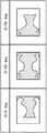
このような構成からなる本発明の実施例2の高周波加熱装置の加熱分布例を図12に示す。マイクロ波空間47は、幅300mm奥行320mm高さ215mmとしている。載置皿43のマイクロ波空間47の底面からの高さは約27mmである。負荷は前述の図8の場合と同様である。
【0076】
加熱アイテムは「全体」キーを選択し誘電体板24の回転速度は毎分15回転とした。加熱分布(a)は載置皿44を停止した場合、加熱分布(b)は載置皿44を毎分6回転させた場合を示す。
【0077】
実施例2のマイクロ波空間47は上記の形状寸法により、マイクロ波空間47内に励振モード<332>(数値はそれぞれマイクロ波空間の幅方法、奥行方向および高さ方向に生じる定在波の山の数を表す。以下同様の表現を用いる)と励振モード<412>を生じさせることができる。そして励振モード<332>に対応した金属壁面上に誘導される高周波電流の流れを分断するように開孔部20を配設している。開孔部20のインピーダンスを大きくすると励振モード<332>が崩れ、励振モード<412>が強くなる。この励振モード<412>はマイクロ波空間47の載置皿の中央部にマイクロ波を集中する励振モードである。
【0078】
誘電体板24のみを連続回転させることで、マイクロ波空間47内には<332>、<332>の崩れ、<412>、<412>の崩れ、および励振モード全て崩れのそれぞれを形成させることができる。これにより、図12(a)に示すような加熱分布を生じさせることができる。一方、誘電体板24の連続回転に載置皿43の回転を重畳させると、図12(b)に示すように被加熱物の周辺部全域を加熱することができる。
【0079】
このように誘電体板24の所定角度支持あるいは連続回転と載置皿の回転有無を組合せることで被加熱物を同心状に加熱したり、周辺部のみを加熱したり、さらには被加熱物全体の加熱の均一化を促進させることができる利便性を大幅に高めた装置を提供できる。
【0080】
誘電体板24のみを連続回転させる制御方法を用いると、被加熱物の中央部を周辺部と同様に強く加熱させることができる。したがって、マイクロ波の浸透深さが小さい食材、たとえばハンバーグやシチュー、茶碗蒸しなどの加熱調理に有効である。
【0081】
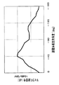
一方載置皿43の回転を重畳させる制御方法について、より効果的な制御方法を以下に説明する。図13は、誘電体板24の回転速度をパラメータとして水200cc、初期温度7±2℃をマイクロ波出力500Wにて1分30秒の加熱をした後の上下方向の温度差を示すものである。容器はマグカップ相当の直径72mmの円筒容器を用いた。
【0082】
図13の特性より、誘電体板24の回転速度を速くすると加熱の均一化が促進できることが認められる。このように誘電体板24を高速回転させる制御方法は、マイクロ波空間内の上下方向のマイクロ波の分散を促進させることが可能であり、底面積に対して嵩高い加熱物の加熱の均一化に有効である。たとえば、牛乳あたため、酒かん、コーヒーあたためなどを最適に加熱させることができる。
【0083】
なお、上記の説明においては誘電体板24の回転駆動手段としてステッピングモータを使用することで上記した様々な誘電体板の制御が容易に達成でき種々な調理方法を提供できる説明をしたが、汎用のモータを用いて高速回転使用に特化した回転駆動仕様でも従来装置と比べて十分に優位性をもった装置を提供できることは明らかである。
【0084】
また、誘電体板の材料は低誘電損失材料を基本とし、ガラス系、セラミックス系あるいは樹脂系が使用できるが、インピーダンス可変手段の構成のコンパクト化および位相差を大きくとるためには材料の比誘電率は少なくとも7以上が望ましい。
【0085】
【発明の効果】
以上のように本発明によれば以下の効果を有する。
【0086】
(1)請求項1の高周波加熱装置によれば、被加熱物を収納するマイクロ波空間を形成する金属壁面に生じる高周波電流の流れを分断するように設けた開孔部のインピーダンスを変えるインピーダンス可変手段と、被加熱物の加熱領域を選択指定する加熱領域選択入力部と、加熱領域選択入力部の入力信号に基づいて前記インピーダンス可変手段を駆動し前記開孔部のインピーダンスを制御する制御部とを備え、インピーダンス可変手段は、開孔部に接続され終端が閉じられた溝部と、溝部内に回転可能に支持された低誘電損失材料の誘電体板と、誘電体板を回転駆動する誘電体板回転駆動手段とから構成され、制御部は前記加熱領域選択入力部の信号に対応して前記誘電体板を所定角度に規定したり連続的に可変制御することにより、マイクロ波空間の金属壁面のインピーダンスを規定することでマイクロ波空間内に生じるマイクロ波の定在波分布を規定する。また、誘電体板の支持角度を連続的に可変することで、開孔部のインピーダンスを連続的に可変しマイクロ波空間内のマイクロ波の定在波分布を時間的に連続可変し、被加熱物上のヒートスポットの発生を解消するとともに被加熱物全体の加熱の均一化を促進することができる。
【0087】
これにより、ユーザは加熱領域選択入力部の中から所望の加熱アイテムを選択してユーザお好みの加熱をすることができる。
【0088】
(2)請求項2の高周波加熱装置によれば、加熱領域選択入力部の入力信号に基いて被加熱物の加熱領域に対応する被加熱物へのマイクロ波の流れを表示する表示手段を備えたことにより、ユーザは選択した加熱アイテムの加熱内容を容易に確認できるとともに加熱後の加熱状態と選択した加熱アイテムとの整合性を認識でき、使い勝手の良い装置を提供できる。
【0089】
(3)請求項3の高周波加熱装置によれば、被加熱物を載置する載置皿と、前記載置皿を回転駆動する載置皿回転駆動手段を備えたことにより、マイクロ波空間内のマイクロ波の定在波の可変制御に被加熱物の回転を重畳させることで被加熱物にはエネルギが細かく分散したマイクロ波を照射させることができ、被加熱物を同心加熱あるいは被加熱物全体の加熱の均一化を効果的に行なうことができる。
【0090】
(4)請求項4の高周波加熱装置によれば、加熱領域選択入力部は、被加熱物の加熱領域を選択指定する入力キーとして少なくともマイクロ波空間内の中央部に収納された被加熱物の中央を加熱する中央加熱モードと前記被加熱物の周辺を加熱する周辺加熱モードとを備えたことにより、様々な形状の被加熱物においてその中央部および周辺部を加熱領域に指定することができる。
【0091】
(5)請求項5の高周波加熱装置によれば、加熱領域選択入力部は、被加熱物の加熱領域を選択指定する入力キーとして少なくともマイクロ波空間内の中央部に収納された被加熱物の中央を加熱する中央加熱モードと前記被加熱物の周辺を加熱する周辺加熱モードとを有し、制御部は、少なくとも周辺加熱モードが選択された時にはその入力信号に基づいて前記載置台回転駆動手段を非動作状態に制御することを特徴としたことにより、異種食材を選択加熱することができる。たとえば、カレーライスの場合、通常ご飯は昇温が速く、カレーは周辺部しか加熱されず中心の温度を高めるのが困難なため、マイクロ波加熱が困難な調理アイテムであったが、カレーが盛り付けられた空間を加熱領域に選択することでカレーにマイクロ波を集中させカレーの昇温を大きくすることができる。
【0092】
(6)請求項6の高周波加熱装置によれば、加熱領域選択入力部は、被加熱物の加熱領域を選択指定する入力キーとして被加熱物全体を加熱領域に選択する全体加熱モードを有し、制御部は前記全体加熱モードが選択された時の入力信号に基づいて、前記開孔部のインピーダンスを連続的に可変制御することを特徴とする。
【0093】
また、(7)請求項7の高周波加熱装置によれば、加熱領域選択入力部は、被加熱物の加熱領域を選択指定する入力キーとして被加熱物全体を加熱領域に選択する全体加熱モードを有し、制御部は前記全体加熱モードが選択された時の入力信号に基づいて、前記開孔部のインピーダンスを連続的に可変制御したり、または前記開孔部のインピーダンスを連続的に可変制御および前記載置皿回転駆動手段を動作状態に制御することを特徴とする。
【0094】
これらにより、開孔部のインピーダンスを連続的に可変制御することで、マイクロ波空間内のマイクロ波の定在波分布を時間的かつ連続的に変化させ、被加熱物の全体加熱を促進させることができる。また、開孔部を特定のインピーダンス値に設定した状態で被加熱物を回転させることで被加熱物の周辺部のみあるいは被加熱物の中央部のみを加熱することができる。さらにはインピーダンス可変と被加熱物の回転を同時に行なうことで被加熱物全体をより均一に加熱することができる。このような制御方法は、牛乳や日本酒のあたためにおいて上下方向の温度差の抑制に大きく寄与できる。
【0095】
(8)請求項8の高周波加熱装置によれば、制御部は加熱領域選択入力部の入力信号に基いて、インピーダンス可変手段を駆動し開孔部のインピーダンスを規定値に制御するとともに被加熱物の加熱時間内にインピーダンス可変手段を駆動して前記規定したインピーダンス値を中心としてインピーダンス値を上下に可変させることを特徴としたことにより、被加熱物のマイクロ波空間内での載置位置に余裕度を持たせることができる。
【0096】
(9)請求項9の高周波加熱装置によれば、誘電体板の支持角度を検出判定する機能を有し、誘電体板を所定角度に回転制御を備えたことにより、加熱領域選択入力信号に基づいた開孔部のインピーダンス値を再現性よく規定することができる。
【0097】
(10)請求項10の高周波加熱装置によれば、支持角度は溝部内のマイクロ波信号に基いて判定することを特徴としたことにより、誘電体板を含む溝部の特性の異変を監視できるとともに別途専用の角度検出手段を不要にできる。
【図面の簡単な説明】
【図1】 本発明の実施例1を示す高周波加熱装置の構成図
【図2】 図1の高周波加熱装置の断面構成図
【図3】 図1の高周波加熱装置のインピーダンス可変手段の構成図
【図4】 本発明の1実施例を示すインピーダンス可変手段の位相差特性図
【図5】 本発明の1実施例を示すマイクロ波センサの検出信号特性図
【図6】 図1の高周波加熱装置の操作部の詳細構成図
【図7】 本発明の高周波加熱装置の加熱制御例を示すフローチャート
【図8】 図1の高周波加熱装置を用いた時の擬似負荷の加熱分布特性図
【図9】 (a)実験用試供品としてご飯にカレーをかけたときの状態図
(b)本発明の高周波加熱装置を用いたときの試供品の実調理における加熱分布特性図 (c)従来の高周波加熱装置を用いたときの試供品の実調理における加熱分布特性図
【図10】本発明の実施例2を示す高周波加熱装置の構成図
【図11】図10の高周波加熱装置の断面構成図
【図12】図10の高周波加熱装置を用いた時の擬似負荷の加熱分布特性図
【図13】図10の高周波加熱装置を用いた時の実調理における加熱特性図
【符号の説明】
10、47 マイクロ波空間
20 開孔部
21 インピーダンス可変手段
23 溝部
24 誘電体板
26、49 加熱領域選択入力部
27、50 表示手段
29 制御部
30 マイクロ波センサ(支持角度検出手段)
36 ステッピングモータ(誘電体板の回転駆動手段)
43 載置皿
44 載置皿駆動手段[0001]
BACKGROUND OF THE INVENTION
The present invention relates to a high-frequency heating device that dielectrically heats an object to be heated using microwave energy, and more particularly to a device that selectively heats an interface of a microwave space to change impedance.
[0002]
[Prior art]
The microwave space of the conventional high-frequency heating device is mainly intended to make the heating of the object to be heated contained in the microwave space uniform. An object rotation method, a multiple power feeding method, or a concave-convex shape of a wall surface of a microwave space has been put into practical use.
[0003]
On the other hand, as a prior art for selectively heating a specific region, there is JP-A-8-153578 using the above-described multiple power feeding method. This publication is provided with a plurality of microwave power feeding parts to a microwave space, and the electric field strength in the central part of the microwave space is increased by microwave radiation from one power feeding part to strongly heat the central part of the object to be heated. However, it discloses that the peripheral portion of the object to be heated is strongly heated by the microwave radiation from the other power feeding portion. And the switching means which switches the microwave radiation from these two electric power feeding parts is provided.
[0004]
Japanese Patent Laid-Open No. 8-330066 discloses that the excitation mode in the microwave space is selectively switched by changing the direction of the current induced on the metal wall surface forming the boundary surface of the microwave space. Yes.
[0005]
[Problems to be solved by the invention]
However, the conventional technology for selectively heating a specific region is to achieve the microwave flow in the microwave space by switching the microwave radiation position to the microwave space containing the object to be heated. It does not change.
[0006]
The flow of microwaves in the microwave space is affected by the shape of the microwave space and the shape and amount of the object to be heated stored in the microwave space, or the placing plate on which the object to be heated is placed. In order to control the flow of microwaves in the wave space, it is necessary to have a function of directly acting on the microwaves existing in the microwave space and changing the action contents with time.
[0007]
In the above prior art, the direct action on the microwave existing in the microwave space is the shape and amount of the object to be heated, and the temporal change factor is the object to be heated accompanying the temperature rise of the object to be heated. Therefore, it is difficult to control the flow of the microwave as desired because the physical space of the object or the space area occupied by the object to be heated is changed. Therefore, it is difficult to concentrate the microwaves in a specific area of the microwave space.
[0008]
On the other hand, the technology for changing the direction of the current induced on the metal wall that forms the boundary surface of the microwave space directly affects the microwave in the microwave space, so that the flow of the microwave in the space can be changed. It is possible. However, this prior art is intended to make the heating of the object to be heated uniform by changing the excitation mode in the microwave space. For example, this technique is effective for a microwave space in which only one excitation mode can occur. I can not expect. Further, in a microwave space where a plurality of excitation modes are generated, it is difficult to say that the excitation mode can be quickly varied with respect to the short-time heat treatment that is a feature of the high-frequency heating device. Furthermore, it is the structure which rotates the opening provided in the metal wall surface, and there exists a danger of producing the spark accompanying rotation control in the environment where the microwave is supplied in the microwave space.
[0009]
The present invention variably controls the heating region of the object to be heated by changing the impedance of the boundary surface forming the microwave space to control the flow of the microwave in the microwave space as desired. The present invention provides a high-frequency heating device that heats a desired specific region or uniformizes heating of the entire object to be heated.
[0010]
[Means for Solving the Problems]
In order to solve the above problems, the high-frequency heating device of the present invention providesA microwave space for containing the object to be heated and substantially confining the supplied microwave; an opening provided to divide a flow of a high-frequency current generated in a metal wall surface forming the microwave space; Impedance variable means for changing the impedance of the opening, a heating area selection input section for selecting and specifying the heating area of the object to be heated, and the impedance variable means for driving the impedance variable means based on an input signal of the heating area selection input section A control unit that controls the impedance of the opening, and the impedance variable means includes a groove connected to the opening and closed at the end, and a low dielectric loss material rotatably supported in the groove. A dielectric plate and a dielectric plate rotation driving means for rotating the dielectric plate, and the control unit corresponds to a signal of the heating region selection input unit. Wherein a dielectric plate intended for variably controlling continuously or defines a predetermined angle.
[0011]
Create a microwave spaceMetal wallConfines microwaves in space, andMetal wallLet ’s propagate in spaceMetal wallIs reflected in space with a phase difference of 180 °.Metal wallBy changing the impedance of theMetal wallThen, the phase difference between the incident wave and the reflected wave of the microwave can be changed.Metal wallIn this case, as described above, the phase difference between the incident wave and the reflected wave is 180 °,Metal wallIs ideally infinite, the phase difference between the incident wave and the reflected wave becomes zero. Inside the microwave spaceMetal wallMicrowave propagating toMetal wallPredetermined standing waves are generated by the microwaves reflected at.
[0012]
Then, the standing wave distribution of the microwave in the microwave space is changed by changing the phase difference between the incident wave and the reflected wave by changing the impedance of the opening provided in the metal wall surface. The standing wave distribution of the microwave in the microwave space is defined by setting the impedance of the aperture to a specified value. Therefore, by setting the impedance of the aperture to a desired value corresponding to the input signal of the heating area selection input unitBy changing the standing wave distribution of the microwave in the microwave space to a desired distribution, the microwave can be concentrated on a specified region of the object to be heated and the region can be heated strongly.
[0013]
And with respect to the opening part of a specific shape, the impedance value of the opening part can be prescribed | regulated by the rotation support angle of the dielectric material board provided in the groove part. Thus, the impedance variable means is a dielectric material, and the impedance can be variably controlled without generating a spark even while the microwave is being supplied into the microwave space. It is possible to carry out fine impedance variable control, that is, variable control of the standing wave distribution of the microwave, during the progress.
[0014]
In addition, by continuously varying the support angle of the dielectric plate, the impedance of the aperture is continuously varied, and the standing wave distribution of the microwave in the microwave space is continuously varied in time to be heated. The generation of heat spots on the object can be eliminated and the uniform heating of the entire object to be heated can be promoted.
[0015]
And by providing the input part which selects and designates the heating area | region of this to-be-heated material, since a user can select and designate a heating area himself, a highly convenient apparatus can be provided.
[0016]
DETAILED DESCRIPTION OF THE INVENTION
The high-frequency heating device according to
[0017]
And in the microwave spaceMetal wallBy defining the impedance, the standing wave distribution of the microwave generated in the microwave space is defined.In addition, by continuously varying the support angle of the dielectric plate, the impedance of the aperture is continuously varied, and the standing wave distribution of the microwave in the microwave space is continuously varied in time to be heated. The generation of heat spots on the object can be eliminated and the uniform heating of the entire object to be heated can be promoted.
Thereby, when the user selects a desired heating item from the heating area selection input unitOpening of metal wallIs set to an impedance value corresponding to the selected heating item, and a desired region of the object to be heated can be heated.
[0018]
The high-frequency heating device according to claim 2 of the present invention is based on the input signal of the heating region selection input section.To the heated object corresponding to the heating area of the heated objectDisplay means for displaying the flow of the microwave is provided. Thereby, the user can easily confirm the heating content of the selected heating item, can recognize the consistency between the heating state after heating and the selected heating item, and can provide a user-friendly device.
[0019]
The present inventionClaim 3The high-frequency heating apparatus includes a mounting tray on which an object to be heated is mounted and a mounting tray rotation driving unit that rotationally drives the mounting tray.
[0020]
Then, by superimposing the rotation of the object to be heated on the variable control of the microwave standing wave in the microwave space, the object to be heated can be irradiated with microwaves with finely dispersed energy. Concentric heating or uniform heating of the entire object to be heated can be effectively performed.
[0021]
The present inventionClaim 4In the high-frequency heating apparatus, the heating area selection input unit heats at least the center of the object to be heated stored in the center part of the microwave space as a heating item for selecting and specifying the heating area of the object to be heated; A peripheral heating mode for heating the periphery of the object to be heated.
[0022]
In this way, by providing a heating item with the central part in the microwave space as a heating area and a heating item with the peripheral part as a heating area, the central part and the peripheral part are heated in the object to be heated in various shapes. Can be specified in the area.
[0023]
The present inventionClaim 5The high-frequency heating deviceThe heating area selection input unit is a central heating mode for heating at least the center of the object to be heated stored in the central part of the microwave space as an input key for selecting and specifying the heating area of the object to be heated, and the periphery of the object to be heated A peripheral heating mode for heating theThe control unit is characterized in that when at least the peripheral heating mode is selected, the mounting table rotation driving means is controlled to a non-operating state based on the input signal.
[0024]
By using such a control method, different types of food can be selectively heated. For example, in the case of curry and rice, the temperature of rice is usually high, and the curry is heated only at the periphery, making it difficult to raise the center temperature. By selecting the created space as the heating region, it is possible to concentrate microwaves on the curry and increase the temperature of the curry. At this time, the rice is heated to a sufficient temperature (about 80 ° C.) by the microwave reflected on the surface of the curry.
[0025]
The present inventionClaim 6In the high frequency heating apparatus, the heating area selection input unit selects and designates the heating area of the object to be heatedInput keyAnd having a whole heating mode for selecting the entire object to be heated as a heating region, and the control unit continuously and variably controls the impedance of the opening portion based on an input signal when the whole heating mode is selected. It is characterized by that.
[0026]
The high-frequency heating apparatus according to claim 7 of the present invention has an overall heating mode in which the heating area selection input unit selects the entire object to be heated as the heating area as an input key for selecting and specifying the heating area of the object to be heated. The control unit continuously variably controls the impedance of the opening portion based on an input signal when the overall heating mode is selected, or continuously variably controls the impedance of the opening portion. The table rotation driving means is controlled to be in an operating state.
[0027]
In this way, by continuously and variably controlling the impedance of the opening, the standing wave distribution of the microwave in the microwave space is changed temporally and continuously, and the entire heating of the object to be heated is promoted. be able to. Moreover, only the peripheral part of a to-be-heated object or only the center part of a to-be-heated object can be heated by rotating a to-be-heated object in the state which set the opening part to the specific impedance value. Furthermore, the entire object to be heated can be more uniformly heated by simultaneously changing the impedance and rotating the object to be heated. Such a control method can greatly contribute to the suppression of the temperature difference in the vertical direction in warming milk and sake.
[0028]
The present inventionClaim 8In the high-frequency heating apparatus, the control unit drives the impedance variable means based on the input signal of the heating region selection input section to control the impedance of the opening portion to a specified value, and the impedance variable means within the heating time of the object to be heated. And the impedance value is varied up and down around the specified impedance value.
[0029]
In this way, by raising or lowering the impedance value around the impedance value with respect to the specified impedance value, a margin can be given to the placement position of the object to be heated in the microwave space.
[0030]
The present inventionClaim 9The high-frequency heating device has a function of detecting and determining the support angle of the dielectric plateRotation control of dielectric plate to a predetermined anglehave.
[0031]
Thus, by providing the function of detecting the support angle of the dielectric plate, the impedance value of the aperture based on the heating region selection input signal can be defined with good reproducibility.
[0032]
The present inventionClaim 10This high frequency heating apparatus is characterized in that the support angle is determined based on a microwave signal in the groove.
[0033]
In this way, it is possible to monitor changes in the characteristics of the groove portion including the dielectric plate by determining the support angle based on the microwave signal in the groove portion, and to eliminate the need for a separate dedicated angle detection means.
[0034]
【Example】
Embodiments of the present invention will be described below with reference to the drawings.
[0035]
Example 1
FIG. 1 is a configuration diagram of a high-frequency heating
[0036]
In FIG. 1 and FIG. 2, a
[0037]
[0038]
[0039]
[0040]
[0041]
Next, the detailed configuration of the impedance variable means will be described with reference to FIG. The
[0042]
The
[0043]
[0044]
The operation and operation of the high-frequency heating device of the present invention having the above configuration will be described below. FIG. 4 shows the characteristics of the phase difference generated between the incident wave and the reflected wave in the opening portion with respect to the support angle of the
[0045]
In FIG. 4, the groove configuration dimensions are L1 = 40 mm, L2 = 30 mm, H1 = 30 mm, the groove width dimension is 80 mm, the
[0046]
From the characteristics shown in FIG. 4, when the support angle of the
[0047]
By using this phase difference variable control, it is possible to provide an apparatus that enables a user to designate a desired heating region in high-frequency heating of an object to be heated. Further, the standing wave distribution can be quickly changed without generating a spark even during microwave heating by a simple configuration in which the dielectric plate is rotated, and fine heating control can be performed as the heating progresses.
[0048]
Next, an embodiment of a method for determining the support angle of the
[0049]
FIG. 5 shows a relative value characteristic of the microwave signal with respect to the support angle of the
[0050]
The support angle determination of the
[0051]
A practical practical embodiment will be described below based on the basic function possessed by the high-frequency heating device of the present invention described above.
[0052]
FIG. 6 is an enlarged view of the
[0053]
Examples of the definition of the support angle of the
[0054]
By displaying the microwave flow in the microwave space, the user can easily confirm the contents of the selected heating item and can recognize the consistency between the heating state after heating and the selected heating item. It can be a good device.
[0055]
The operation procedure and control contents when using this apparatus will be described with reference to FIG. After the object to be heated is stored in the microwave space, the user determines a heating area for heating the object to be heated and selects one of the heating items described above (S101). Next, after inputting the heating time (S102), the microwave heating of the object to be heated is started by pressing the “start” key shown in FIG. 6 (S103).
[0056]
Based on the above input information, the
[0057]
In S106, the heating state of the object to be heated is monitored. When the heating end determination in S107 is “Yes”, it is determined that the heating is ended. In S108, the operation of the inverter drive
[0058]
The contents of the monitoring of the heating state from S106 to S107 and the end determination based thereon are the information on the heating time input from the
[0059]
In addition, control content S110, S111 enclosed with the broken line in FIG. 7 is the control content applied with respect to the apparatus provided with the drive means which rotationally drives the mounting tray which mounts the to-be-heated material mentioned later. .
[0060]
Next, FIG. 8 shows an example of heating distribution in a microwave space configuration without a rotation driving system for the placing plate on which the object to be heated shown in FIG. 1 is placed. FIG. 8 shows a heating distribution using Adhair Glue (registered trademark) 200 g manufactured by Sekisui Resin Co., Ltd. The
[0061]
In addition, Adhair synthetic glue (registered trademark) is a polyvinyl alcohol aqueous solution, which is transparent at normal temperature, but has a property of becoming cloudy when the temperature is 45 ° C. or higher.
[0062]
The microwave output is 500 W and shows the heating distribution after heating for 40 seconds, and the white area is the heated area. The white area, that is, the heating area can be changed by changing the support angle of the dielectric plate 24.sowear. The support angle of the
[0063]
As described above, by providing the “center” heating item with the central portion in the microwave space as the heating region and the “left” and “right” heating items with the peripheral portion as the heating region, various shapes or arrangements of covered items are provided. It is possible to provide an apparatus capable of freely designating the central portion and the peripheral portion of the heated object as a heating region and performing optimum heating or user preference according to the object to be heated.
[0064]
As is well known, Adhair paste has a larger dielectric loss and a smaller penetration depth than water. In the case of an ad hair paste load, the “center” heating item is illustrated data in which the center portion is not sufficiently heated. However, in a normal food, the “center” heating item can be used to achieve center heating.
[0065]
Next, an example of the actual cooking menu will be described with reference to FIG. FIG. 9 shows a temperature distribution when curry rice (both at room temperature: about 20 ° C.) is microwave heated. Curry is on the right side of the figure. The temperature distribution (a) is when the “right” heating item of the apparatus of the present invention is used, while the temperature distribution (b) is when the conventional mounting plate rotation drive type high frequency heating apparatus is used. The heating content is 500 W for 2 minutes and 30 seconds.
[0066]
Moreover, in foodstuffs such as curry and rice, the manner in which curry is arranged varies, and further, the serving dish is not always placed at the center of the microwave space. An improved control method for enabling the heating region control of the present invention to be used effectively even in such an actual use environment will be described.
[0067]
This control method is to vibrate within a range of, for example, ± 9 ° (corresponding to one step of the stepping motor) around the angle that defines the support angle of the
[0068]
As described above, the control method of changing the standing wave distribution of the microwave in the
[0069]
FIG. 9 shows an example when different materials are heated. FIG. 9A shows a case where rice is placed on a plate and curled on one side (shaded area in the drawing). In FIG. 9C heated by the conventional apparatus, the curry is hardly heated, and the rice is heated to a temperature range (black area in the figure) exceeding the upper limit temperature of 80 ° C., which is said to be delicious. On the other hand, in FIG.9 (b) heated with the apparatus of this invention, the temperature of rice is a maximum of 80 degreeC, and the curry is also heated to about 60 degreeC. Therefore, a delicious meal can be eaten immediately after the end of heating.
[0070]
(Example 2)
FIG. 10 is a configuration diagram of a high-frequency heating device showing Embodiment 2 of the present invention, and FIG. 11 is a cross-sectional configuration diagram of FIG. In the figure, members that are the same as or equivalent to those in the first embodiment are denoted by the same reference numerals.
[0071]
The difference between the second embodiment and the first embodiment is that a loading tray driving means 44 that rotationally drives a
[0072]
The
[0073]
The
[0074]
The impedance varying means 21 that varies the impedance of the
[0075]
FIG. 12 shows a heating distribution example of the high-frequency heating device according to the second embodiment of the present invention having such a configuration. The
[0076]
For the heating item, the “overall” key was selected, and the rotational speed of the
[0077]
The
[0078]
By continuously rotating only the
[0079]
In this manner, the object to be heated is concentrically heated by supporting the
[0080]
If a control method in which only the
[0081]
On the other hand, a more effective control method will be described below for the control method for superimposing the rotation of the mounting
[0082]
From the characteristics shown in FIG. 13, it is recognized that uniform heating can be promoted by increasing the rotational speed of the
[0083]
In the above description, the stepping motor is used as the rotational driving means for the
[0084]
In addition, the material of the dielectric plate is basically a low dielectric loss material, and glass, ceramics, or resin can be used. In order to make the impedance variable means compact and to increase the phase difference, the relative dielectric of the material is used. The rate is preferably at least 7 or more.
[0085]
【The invention's effect】
As described above, the present invention has the following effects.
[0086]
(1) According to the high-frequency heating device of
[0087]
thisThus, the user can select a desired heating item from the heating area selection input unit and perform heating as desired by the user.
[0088]
(2) According to the high frequency heating device of the second aspect, based on the input signal of the heating region selection input section.To the heated object corresponding to the heating area of the heated objectBy providing a display means for displaying the flow of the microwave, the user can easily confirm the heating content of the selected heating item and can recognize the consistency between the heating state after heating and the selected heating item, which is easy to use. A good device can be provided.
[0089]
(3Claim3According to the high frequency heating apparatus of the present invention, by providing the mounting tray on which the object to be heated is mounted and the mounting tray rotation driving means for rotationally driving the mounting tray, the microwaves in the microwave space By superimposing the rotation of the object to be heated on the variable control of the wave, the object to be heated can be irradiated with microwaves with finely dispersed energy, and the object to be heated is concentrically heated or the entire object to be heated is made uniform. Can be performed effectively.
[0090]
(4Claim4According to the high frequency heating apparatus, the heating area selection input unit selects and designates the heating area of the object to be heated.Input keyAs a center heating mode for heating at least the center of the object to be heated stored in the center of the microwave space and a peripheral heating mode for heating the periphery of the object to be heated. In the object, the central part and the peripheral part can be designated as the heating region.
[0091]
(5Claim5According to the high-frequency heating device ofThe heating area selection input unit is a central heating mode for heating at least the center of the object to be heated stored in the central part of the microwave space as an input key for selecting and specifying the heating area of the object to be heated, and the periphery of the object to be heated A peripheral heating mode for heating theThe control unitSmallAt least when the peripheral heating mode is selected, the table rotation driving means is controlled to be in a non-operating state based on the input signal, so that different kinds of food can be selectively heated. For example, in the case of curry and rice, the temperature of rice is usually high, and the curry is heated only at the periphery, making it difficult to raise the center temperature. By selecting the created space as the heating region, it is possible to concentrate microwaves on the curry and increase the temperature of the curry.
[0092]
(6Claim6According to the high frequency heating apparatus, the heating area selection input unit selects and designates the heating area of the object to be heated.Input keyAs a heating area for selecting the whole object to be heated as a heating area, and the control unit continuously variably controls the impedance of the opening portion based on an input signal when the whole heating mode is selected.It is characterized by doing.
[0093]
(7) According to the high-frequency heating device of claim 7, the heating area selection input unit selects the entire heating mode as the heating area as an input key for selecting and specifying the heating area of the heating object. And the control unit continuously variably controls the impedance of the aperture or continuously variably controls the impedance of the aperture based on an input signal when the overall heating mode is selected. And the above-mentioned plate rotation drive means is controlled to an operation state, It is characterized by the above-mentioned.
[0094]
theseBy continuously and variably controlling the impedance of the aperture, the standing wave distribution of the microwave in the microwave space can be changed temporally and continuously, and the entire heating of the object to be heated can be promoted. it can. Moreover, only the peripheral part of a to-be-heated object or only the center part of a to-be-heated object can be heated by rotating a to-be-heated object in the state which set the opening part to the specific impedance value. Furthermore, the entire object to be heated can be more uniformly heated by simultaneously changing the impedance and rotating the object to be heated. Such a control method can greatly contribute to the suppression of the temperature difference in the vertical direction in warming milk and sake.
[0095]
(8Claim8According to the high-frequency heating apparatus, the control unit drives the impedance variable means based on the input signal of the heating region selection input unit to control the impedance of the opening portion to a specified value and the impedance within the heating time of the object to be heated. By driving the variable means to vary the impedance value up and down around the specified impedance value, it is possible to give a margin to the placement position of the object to be heated in the microwave space. it can.
[0096]
(9Claim9According to the high-frequency heating device, the function of detecting and determining the support angle of the dielectric plateRotation control of the dielectric plate to a predetermined angleSince the impedance value of the opening portion based on the heating region selection input signal can be defined with good reproducibility.
[0097]
(10Claim10According to the high frequency heating apparatus of the present invention, the support angle is determined based on the microwave signal in the groove portion, so that it is possible to monitor the change in the characteristics of the groove portion including the dielectric plate and to provide a dedicated angle detection means. Can be made unnecessary.
[Brief description of the drawings]
FIG. 1 is a configuration diagram of a high-frequency heating
FIG. 2 is a cross-sectional configuration diagram of the high-frequency heating device of FIG.
3 is a configuration diagram of impedance variable means of the high-frequency heating device of FIG.
FIG. 4 is a phase difference characteristic diagram of impedance variable means showing one embodiment of the present invention.
FIG. 5 is a detection signal characteristic diagram of a microwave sensor showing one embodiment of the present invention.
6 is a detailed configuration diagram of an operation unit of the high-frequency heating device of FIG.
FIG. 7 is a flowchart showing a heating control example of the high-frequency heating device of the present invention.
8 is a heating distribution characteristic diagram of a pseudo load when the high-frequency heating device of FIG. 1 is used.
[Fig. 9] (a) State diagram when curry is applied to rice as a test sample.
(B) Heating distribution characteristic diagram in actual cooking of sample when using high-frequency heating device of the present invention (c) Heating distribution characteristic diagram in actual cooking of sample when using conventional high-frequency heating device
FIG. 10 is a configuration diagram of a high-frequency heating device showing Embodiment 2 of the present invention.
11 is a cross-sectional configuration diagram of the high-frequency heating device of FIG. 10;
12 is a heating distribution characteristic diagram of a pseudo load when the high-frequency heating device of FIG. 10 is used.
13 is a heating characteristic diagram in actual cooking when using the high-frequency heating device of FIG.
[Explanation of symbols]
10, 47 Microwave space
20 Opening part
21 Impedance variable means
23 Groove
24 Dielectric plate
26, 49 Heating area selection input section
27, 50 Display means
29 Control unit
30 Microwave sensor (support angle detection means)
36 Stepping motor (dielectric plate rotation drive means)
43 Placement dish
44 Loading tray driving means
Claims (10)
Priority Applications (1)
| Application Number | Priority Date | Filing Date | Title |
|---|---|---|---|
| JP08581799A JP4306005B2 (en) | 1999-03-29 | 1999-03-29 | High frequency heating device |
Applications Claiming Priority (1)
| Application Number | Priority Date | Filing Date | Title |
|---|---|---|---|
| JP08581799A JP4306005B2 (en) | 1999-03-29 | 1999-03-29 | High frequency heating device |
Publications (3)
| Publication Number | Publication Date |
|---|---|
| JP2000277250A JP2000277250A (en) | 2000-10-06 |
| JP2000277250A5 JP2000277250A5 (en) | 2006-03-09 |
| JP4306005B2 true JP4306005B2 (en) | 2009-07-29 |
Family
ID=13869424
Family Applications (1)
| Application Number | Title | Priority Date | Filing Date |
|---|---|---|---|
| JP08581799A Expired - Fee Related JP4306005B2 (en) | 1999-03-29 | 1999-03-29 | High frequency heating device |
Country Status (1)
| Country | Link |
|---|---|
| JP (1) | JP4306005B2 (en) |
Families Citing this family (2)
| Publication number | Priority date | Publication date | Assignee | Title |
|---|---|---|---|---|
| JP4635294B2 (en) * | 2000-04-21 | 2011-02-23 | パナソニック株式会社 | High frequency heating device |
| JP5064924B2 (en) * | 2006-08-08 | 2012-10-31 | パナソニック株式会社 | Microwave processing equipment |
-
1999
- 1999-03-29 JP JP08581799A patent/JP4306005B2/en not_active Expired - Fee Related
Also Published As
| Publication number | Publication date |
|---|---|
| JP2000277250A (en) | 2000-10-06 |
Similar Documents
| Publication | Publication Date | Title |
|---|---|---|
| US5828042A (en) | Uniform heating apparatus for microwave oven and method thereof | |
| CN101897234B (en) | Cooking device | |
| CN101903705A (en) | Cooker | |
| US6469286B1 (en) | Variable-impedance unit, microwave device using the unit, and microwave heater | |
| JP2009144970A5 (en) | ||
| JP2009129844A5 (en) | ||
| JP4306005B2 (en) | High frequency heating device | |
| WO2000003564A1 (en) | Variable-impedance unit, microwave device using the unit, and microwave heater | |
| JP2004327260A (en) | Heating cooker | |
| JP2936966B2 (en) | Cooking device | |
| JP2018088363A (en) | Heating cooker | |
| JP3063643B2 (en) | Heating equipment | |
| JP2004012095A (en) | High-frequency heating cooking device | |
| JPH06260275A (en) | High frequency heating device | |
| JP2001307868A (en) | High-frequency heating device | |
| JP4635294B2 (en) | High frequency heating device | |
| JP4457430B2 (en) | High frequency heating device | |
| WO2008084668A1 (en) | Microwave oven | |
| JP2010127469A (en) | Microwave heating device | |
| JPH0719486A (en) | Microwave oven | |
| JP2004069088A (en) | High frequency heating device | |
| JPH08306483A (en) | Cooking appliance | |
| JPH06163155A (en) | High frequency heating device | |
| KR200342081Y1 (en) | Vessel for cooking an egg in a microwave oven | |
| JP2001304582A (en) | High frequency heating device |
Legal Events
| Date | Code | Title | Description |
|---|---|---|---|
| A521 | Written amendment |
Free format text: JAPANESE INTERMEDIATE CODE: A523 Effective date: 20060124 |
|
| A621 | Written request for application examination |
Free format text: JAPANESE INTERMEDIATE CODE: A621 Effective date: 20060124 |
|
| RD01 | Notification of change of attorney |
Free format text: JAPANESE INTERMEDIATE CODE: A7421 Effective date: 20060214 |
|
| A131 | Notification of reasons for refusal |
Free format text: JAPANESE INTERMEDIATE CODE: A131 Effective date: 20080805 |
|
| A521 | Written amendment |
Free format text: JAPANESE INTERMEDIATE CODE: A523 Effective date: 20081003 |
|
| TRDD | Decision of grant or rejection written | ||
| A01 | Written decision to grant a patent or to grant a registration (utility model) |
Free format text: JAPANESE INTERMEDIATE CODE: A01 Effective date: 20090414 |
|
| A01 | Written decision to grant a patent or to grant a registration (utility model) |
Free format text: JAPANESE INTERMEDIATE CODE: A01 |
|
| A61 | First payment of annual fees (during grant procedure) |
Free format text: JAPANESE INTERMEDIATE CODE: A61 Effective date: 20090427 |
|
| FPAY | Renewal fee payment (event date is renewal date of database) |
Free format text: PAYMENT UNTIL: 20120515 Year of fee payment: 3 |
|
| FPAY | Renewal fee payment (event date is renewal date of database) |
Free format text: PAYMENT UNTIL: 20130515 Year of fee payment: 4 |
|
| FPAY | Renewal fee payment (event date is renewal date of database) |
Free format text: PAYMENT UNTIL: 20130515 Year of fee payment: 4 |
|
| FPAY | Renewal fee payment (event date is renewal date of database) |
Free format text: PAYMENT UNTIL: 20140515 Year of fee payment: 5 |
|
| LAPS | Cancellation because of no payment of annual fees |