JP4304263B2 - Non-parallel dovetail surface fabrication method and dovetail assembly - Google Patents
Non-parallel dovetail surface fabrication method and dovetail assembly Download PDFInfo
- Publication number
- JP4304263B2 JP4304263B2 JP2002247940A JP2002247940A JP4304263B2 JP 4304263 B2 JP4304263 B2 JP 4304263B2 JP 2002247940 A JP2002247940 A JP 2002247940A JP 2002247940 A JP2002247940 A JP 2002247940A JP 4304263 B2 JP4304263 B2 JP 4304263B2
- Authority
- JP
- Japan
- Prior art keywords
- blade
- disk
- dovetail
- rotor
- relief
- Prior art date
- Legal status (The legal status is an assumption and is not a legal conclusion. Google has not performed a legal analysis and makes no representation as to the accuracy of the status listed.)
- Expired - Fee Related
Links
- 238000000034 method Methods 0.000 title claims description 10
- 238000004519 manufacturing process Methods 0.000 title description 2
- 210000000078 claw Anatomy 0.000 claims description 20
- 150000001875 compounds Chemical class 0.000 claims description 12
- 239000002131 composite material Substances 0.000 claims description 7
- 239000007789 gas Substances 0.000 description 14
- 239000000567 combustion gas Substances 0.000 description 7
- 238000011144 upstream manufacturing Methods 0.000 description 3
- 230000000712 assembly Effects 0.000 description 2
- 238000000429 assembly Methods 0.000 description 2
- 230000009286 beneficial effect Effects 0.000 description 1
- 238000002485 combustion reaction Methods 0.000 description 1
- 230000000295 complement effect Effects 0.000 description 1
- 238000001816 cooling Methods 0.000 description 1
- 238000010586 diagram Methods 0.000 description 1
- 239000000428 dust Substances 0.000 description 1
- 239000000446 fuel Substances 0.000 description 1
- 238000012986 modification Methods 0.000 description 1
- 230000004048 modification Effects 0.000 description 1
- 230000003068 static effect Effects 0.000 description 1
Images

Classifications
-
- F—MECHANICAL ENGINEERING; LIGHTING; HEATING; WEAPONS; BLASTING
- F01—MACHINES OR ENGINES IN GENERAL; ENGINE PLANTS IN GENERAL; STEAM ENGINES
- F01D—NON-POSITIVE DISPLACEMENT MACHINES OR ENGINES, e.g. STEAM TURBINES
- F01D5/00—Blades; Blade-carrying members; Heating, heat-insulating, cooling or antivibration means on the blades or the members
- F01D5/30—Fixing blades to rotors; Blade roots ; Blade spacers
- F01D5/3007—Fixing blades to rotors; Blade roots ; Blade spacers of axial insertion type
-
- Y—GENERAL TAGGING OF NEW TECHNOLOGICAL DEVELOPMENTS; GENERAL TAGGING OF CROSS-SECTIONAL TECHNOLOGIES SPANNING OVER SEVERAL SECTIONS OF THE IPC; TECHNICAL SUBJECTS COVERED BY FORMER USPC CROSS-REFERENCE ART COLLECTIONS [XRACs] AND DIGESTS
- Y10—TECHNICAL SUBJECTS COVERED BY FORMER USPC
- Y10T—TECHNICAL SUBJECTS COVERED BY FORMER US CLASSIFICATION
- Y10T29/00—Metal working
- Y10T29/49—Method of mechanical manufacture
- Y10T29/49316—Impeller making
- Y10T29/4932—Turbomachine making
- Y10T29/49321—Assembling individual fluid flow interacting members, e.g., blades, vanes, buckets, on rotary support member
Landscapes
- Engineering & Computer Science (AREA)
- Mechanical Engineering (AREA)
- General Engineering & Computer Science (AREA)
- Turbine Rotor Nozzle Sealing (AREA)
Description
【0001】
【発明の属する技術分野】
本出願は、一般的にガスタービンエンジンのロータ組立体に関し、より具体的には、取り外し可能なタービンブレードをタービンディスクに取り付けるための方法及び装置に関する。
【0002】
【発明の背景】
ガスタービンエンジンにおいては、空気が、圧縮機中で加圧され、燃焼器中で燃料と混合されて高温の燃焼ガスを発生する。高温の燃焼ガスは1つ又はそれ以上のタービンに導かれ、該タービンにおいてエネルギーが取り出される。ガスタービンは周方向に間隔を置いて配置されたロータブレードの少なくとも1つの列を含む。
【0003】
ガスタービンエンジンのロータブレードは、前縁及び後縁と、正圧側面と、負圧側面とを有する翼形部を含む。正圧側面及び負圧側面は、翼形部前縁と後縁で接合され、ロータブレードのプラットホームから半径方向に延びる。各ロータブレードはまた、プラットホームから半径方向内向きのダブテールを含み、該ダブテールがロータブレードをロータディスクに取り付けるのを助ける。
【0004】
各ガスタービンロータディスクは複数のダブテールスロットを含み、ロータブレードをロータディスクに結合するのを助ける。各ダブテールスロットは、ディスクフィレットと、ディスク圧力面と、ディスクリリーフ面とを含む。ロータブレードダブテールは、ロータブレードがロータディスクから半径方向外向きに延びるように、ロータディスクのダブテールスロット内に受けられる。
【0005】
ダブテールは、一般的にダブテールスロットに対して相補形であり、互いに嵌まり合ってダブテール組立体を形成する。ダブテールは、ダブテールスロットのディスクフィレット中に取り付けられる少なくとも一対の爪を含む。ダブテール爪は、ディスク圧力面に対向するブレード圧力面と、ディスクリリーフ面に対向するブレードリリーフ面とを含む。矛盾する設計要因に適応するために、少なくとも一部の公知のダブテール組立体は、対向する圧力面が係合した時、対向するリリーフ面の間に延びるリリーフ間隙を含んでいる。
【0006】
運転中に、タービンは、一般的に燃焼ガスにより回転される。時折、エンジンの内部の燃焼が終了した時、エンジンを通過する大気が、極めて低い速度でタービンを回転させることがある。このような状態は、「風車状態」と呼ばれる。風車状態の間は小さい遠心力が発生して、ブレード圧力面をディスク圧力面から離れさせる。ダブテールは、ブレードリリーフ面がディスクリリーフ面に係合するように、移動する。ダブテールの移動はまた、ブレード圧力面とディスク圧力面との間に圧力面間隙を形成する。ロータブレードの移動により、風車状態の間にプラットホーム下流側ウイングと第2段ノズルの前方部分との間の穏やかな接触によるノイズを含む可聴ノイズを発生する可能性がある。圧力面間隙を伴った状態で連続して運転すれば、対向する圧力面の間に塵埃又は異物が入り込む結果になり、そのことによりロータブレードの不整合と圧力面のブリネリング(Brinelling:繰り返し衝撃又は静的な過負荷によって起こされる表面損傷)とを引き起こす可能性がある。
【特許文献1】
米国特許5,622,475号
【0007】
【発明の概要】
例示的な実施形態において、ダブテール組立体は、ガスタービンエンジンにおける圧力面のブリネリングを減少させるのを助ける非平行リリーフ面を含む。ダブテール組立体は、ダブテールを含む複数のロータブレードを含む。各ダブテールは、ブレードリリーフ面を含む少なくとも一対のブレード爪を含む。ダブテール組立体はまた、ダブテールを受ける寸法にされた複数のダブテールスロットを含むロータディスクを含む。各ダブテールスロットは、ディスクリリーフ面を含む少なくとも一対の対向するディスク爪により形成される。ダブテール組立体は、ダブテールがロータディスクに結合された時、ディスクリリーフ面がブレードリリーフ面に対して非平行になるような形状にされる。
【0008】
本発明の別の態様においては、ガスタービンエンジン用のロータディスクを製作する方法は、ロータブレードの半径方向の移動を減少するのを助ける。ロータディスクは、少なくとも一対のディスク爪により形成されたダブテールスロットを含む。ロータブレードは、少なくとも一対のブレード爪を含むダブテールを含む。本方法は、ブレード圧力面を少なくとも1つのブレード爪上に形成する段階と、ロータブレードがロータディスク内に取り付けられた時、ディスク圧力面がブレード圧力面に対して実質的に平行になるように、ディスク圧力面を少なくとも1つのディスク爪上に形成する段階とを含む。本方法は、ブレードリリーフ面を少なくとも1つのブレード爪上に形成する段階と、ロータブレードがロータディスク内に取り付けられ、ディスク圧力面がブレード圧力面に係合した時、ディスクリリーフ面がブレードリリーフ面に対して実質的に非平行になるように、ディスクリリーフ面を少なくとも1つのディスク爪上に形成する段階とを更に含む。その結果、ブレードリリーフ面とディスクリリーフ面とは、減少したリリーフ間隙を形成し、それによってタービンの風車状態にある間に圧力面の間に異物が入り込むのを制限し、またロータブレードの落下により生じるノイズを減少させるのを助ける。
【0009】
【発明の実施の形態】
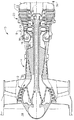
図1は、低圧圧縮機12と、高圧圧縮機14と、燃焼器16とを含むガスタービンエンジン10の概略図である。エンジン10はまた、高圧タービン18と、低圧タービン20と、ケーシング22とを含む。高圧タービン18は、複数のロータブレード24と、第1の軸28に結合されたロータディスク26とを含む。第1の軸28は、高圧圧縮機14と高圧タービン18とを結合する。第2の軸30が、低圧圧縮機12と低圧タービン20とを結合する。エンジン10は、エンジン10の上流側34から後方にエンジン10の下流側36まで延びる対称軸線32を有する。1つの実施形態において、ガスタービンエンジン10は、オハイオ州シンシナチにあるGeneral Electric Companyから市販されているGE90型エンジンである。
【0010】
運転中に、低圧圧縮機12は、加圧した空気を高圧圧縮機14に供給する。高圧圧縮機14は高度に加圧した空気を燃焼器16に供給する。燃焼器16からの燃焼ガス38はタービン18及び20を駆動する。
【0011】
高圧タービン18は、第1の軸28、従って高圧圧縮機14を回転させ、一方低圧タービン20は第2の軸30及び低圧圧縮機12を軸線32の周りで回転させる。
【0012】
図2は、ロータディスク26内に取り付けられた複数のロータブレード24を含むディスク組立体37の部分斜視図である。1つの実施形態において、複数のロータブレード24は、ガスタービンエンジ10の高圧タービンロータブレード段(図示せず)を形成する。ロータブレード24は、ロータディスク26内に取り付けられて、ロータディスク26から半径方向外向きに延びる。
【0013】
ガスタービンエンジンのロータブレード24の各々は、翼形部40と、プラットホーム42と、ダブテール44とを含む。各翼形部40は、前縁46と、後縁48と、正圧側面50と、負圧側面52とを含む。正圧側面50及び負圧側面52は、翼形部40の前縁46と軸方向に間隔を置いて配置された後縁48とにおいて結合される。翼形部40は、プラットホーム42から半径方向外向きに延びる。
【0014】
プラットホーム42は、上流側ウイング54と下流側ウイング56とを含む。ダブテール44は、プラットホーム42から半径方向内向きに延び、ロータブレード24をロータディスク26に固定するのを助ける。プラットホーム42は、燃焼ガス38の下流方向の流れの境界となり、かつそれを導く。
【0015】
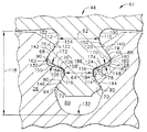
図3は、ダブテール44とダブテールスロット60の拡大断面図である。ダブテール44は、ダブテールスロット60内に取り付けられ、ダブテールスロット60と協働してダブテール組立体61を形成する。例示的な実施形態において、ダブテール44は、ブレード上部の最小頚部62と、ブレード下部の最小頚部64と、上部の対のブレード爪66及び68と、下部の対のブレード爪70及び72とを含む。別の実施形態において、ダブテール44は、一対のブレード爪66及び68のみを含む。ダブテール44はまた、一対の上部ブレード圧力面74及び76と、一対の下部ブレード圧力面78及び80と、一対のブレードリリーフ面82及び84とを含む。各ブレード爪66、68、70、及び72は、ブレード面に隣接して設置されたブレード爪外側丸み88、90、92、及び94を含む。例えば、爪66に関して言えば、外側丸み88は、ブレード圧力面74とブレードリリーフ面82との間にある。ダブテール44はまた、それぞれのブレード内側丸み110、112、114、及び116を含むブレードフィレット100、102、104、及び106を含む。
【0016】
各ガスタービンロータディスク26は、ロータブレード24を取り付けるのを助ける複数のダブテールスロット60を形成する。各ダブテールスロット60は、半径方向に延びるスロット長さ118を定める。この例示的な実施形態において、ダブテールスロット60は、一対の上部ディスク爪120及び122と、一対の下部ディスク爪124及び126と、一対の上部ディスクフィレット128及び130と、スロット底部132とを含む。ダブテールスロット60はまた、一対の上部ディスク圧力面140及び142と、一対の下部ディスク圧力面144及び146と、一対のディスクリリーフ面148及び150とを含む。各ディスク爪120、122、124、及び126は、ディスク面に隣接して設置されたディスク爪外側丸み152、154、156、及び158を含む。例えば、ディスク爪外側丸み156は、ディスク圧力面144とディスクリリーフ面148との間にある。ダブテールスロットの上部ディスクフィレット128及び130は、ディスクフィレット内側丸み160及び162を更に含む。
【0017】
複数のリリーフ間隙170及び172は、ブレード圧力面74、76、78、及び80がそれぞれのディスク圧力面140、142、144、及び146と接触している時、対向するブレードリリーフ面82及び84とディスクリリーフ面148及び150との間に延びる。リリーフ間隙170及び172は、ダブテール組立体の冷却と熱膨張を助ける。
【0018】
ブレード圧力面74、76、78、及び80は、それぞれのディスク圧力面140、142、144、及び146に対して実質的に平行であり、係合を助け、かつタービン回転中に生じる負荷を支持する。それぞれの対向するブレードリリーフ面82及び84とディスクリリーフ面148及び150とは、互いに対して非平行である。非平行なブレードリリーフ面82及び84とディスクリリーフ面148及び150とは、リリーフ間隙170及び172を所定の距離まで減少させるのを助ける。例示的な実施形態において、各リリーフ間隙170及び172は、くさび形であり、ディスク爪外側丸み156及び158に隣接する頂点174及び176を含む。
【0019】
ディスクフィレット内側丸み160及び162は、それぞれ複合丸みであり、それぞれのブレード爪66及び68よりもそれぞれ大きい。複合丸み160及び162は、スロット長さ118を短縮しながら、集中応力を上部ディスクフィレット128及び130中に分散するのを助ける。例示的な実施形態において、ディスクフィレット128のみについて考察すれば、例えば、複合丸み160は、より大きい丸み部分180とより小さい丸み部分182とを含む。より小さい丸み部分182がディスクフィレット128の大きさを制限しながら、より大きい丸み部分180が応力をロータディスク26に分散する。リリーフ面148は、より小さい丸み部分182に隣接してリリーフ間隙170を減少させる。より大きい丸み部分180は、より大きいフィレットを助け、より小さい非複合丸みのフィレット(図示せず)に比較して上部ディスクフィレット128付近のロータディスク26中の応力を減少させる。より小さい丸み部分182を有するディスクフィレット複合内側丸み160は、スロット長さ118を短縮するのを助けて、ロータディスク26の強度を向上させる。
【0020】
ディスク爪外側丸み156と158もまた、複合丸みである。ここでも、ディスク爪124のみについて考察すれば、外側丸み156は、より大きい丸み部分184とより小さい丸み部分186とを含み、下部ブレードフィレット104を受けて係合するのを助ける。ディスク爪複合外側丸み156は、ディスクリリーフ面148により切り詰められる。ディスク爪複合丸み156は、非平行なブレードリリーフ面82の形成を助け、リリーフ間隙170及び172を減少させる。より小さい丸み部分186を有するディスク爪複合丸み156はまた、スロット長さ118を短縮するのを助け、従ってロータディスク26の強度を向上させる。
【0021】
別の実施形態において、ダブテール44は、ブレード爪66及び68上に複合丸みを備えて形成される。ブレードリリーフ面82及び84により切り詰められた状態で、ブレード爪外側丸み88及び90は、それぞれが複合丸みであり、受けるディスクフィレット内側丸み160及び162より大きい丸みを含む。リリーフ面82及び84はまた、複合丸みであるそれぞれのブレードフィレット内側丸み114及び116を切り詰める。
【0022】
別の実施形態においては、ブレード爪66、68、70、及び72と、ブレードフィレット100、102、104、及び106と、ディスク爪120、122、124、及び126と、ディスクフィレット128及び130とは、全て複合丸みを有してもよい。
【0023】
運転中に、燃焼ガス38は、ロータブレード24に突き当たり、エネルギーを与えてタービン20を回転させる。タービン20の回転により生じる遠心力が、ブレード圧力面74、76、78、及び80をディスク圧力面140、142、144、及び146と係合させ、それらに負荷を掛ける。リリーフ間隙170及び172が、ブレードリリーフ面82及び84とディスクリリーフ面148及び150との間に形成される。
【0024】
非平行なブレードリリーフ面82及び84とディスクリリーフ面148及び150とが、ロータブレード24の移動を減少させるのを助け、異物が入り込む可能性を制限する。運転中には、燃焼ガス38が、ロータブレード24に突き当たり、ロータディスク26を回転させる。ブレード圧力面74、76、78、及び80が、ディスク圧力面140、142、144、及び146に係合して、ブレードリリーフ面82及び84とディスクリリーフ面148及び150との間にリリーフ間隙170及び172を形成する。非平行なブレードリリーフ面82及び84とディスクリリーフ面148及び150とは、エンジン10が風車状態になった時に、ロータブレード24の移動を減少させ、異物が入り込む可能性を制限し、またロータブレード落下により生じるノイズを制限する。
【0025】
その上に、複合丸みを有するディスク爪外側丸み156及び158は、公知のロータディスク及びダブテールと比較して、スロット長さ118を短縮するのを助ける。スロット長さを短縮することは、高速タービンロータ設計に有益である。
【0026】
上述のロータブレードは、費用効果がよくかつ高い信頼性がある。ロータブレードは、ディスクダブテールスロット内に受けられるダブテールを含む。非平行リリーフ面が、ロータが風車状態にある時にロータブレードの移動を減少させるのを助ける。その結果、圧力面に生じる摩耗が少なくなり、費用効果が良くかつ信頼性のある方法でロータブレードの有効寿命を延長する。更に、ロータプラットホームと次段のノズルとの間に生じる不快なノイズを、減少させることも助ける。
【0027】
本発明を、様々な特定の実施形態について説明してきたが、本発明が特許請求の範囲の技術思想及び技術的範囲内の変更で実施可能であることは、当業者には明らかであろう。特許請求の範囲に記載された符号は、理解容易のためであってなんら発明の技術的範囲を実施例に限縮するものではない。
【図面の簡単な説明】
【図1】 ガスタービンエンジンの概略図。
【図2】 図1に示すガスタービンエンジンと共に用いることができるロータブレードの部分斜視図。
【図3】 図2に示すロータブレードと共に用いることができるダブテールとダブテールスロットの拡大断面図。
【符号の説明】
24 ロータブレード
26 ロータディスク
37 ディスク組立体
40 翼形部
42 プラットホーム
44 ダブテール
46 前縁
48 後縁
50 正圧側面
52 負圧側面
54 上流側ウイング
56 下流側ウイング
60 ダブテールスロット[0001]
BACKGROUND OF THE INVENTION
The present application relates generally to gas turbine engine rotor assemblies and, more particularly, to a method and apparatus for attaching removable turbine blades to a turbine disk.
[0002]
BACKGROUND OF THE INVENTION
In a gas turbine engine, air is pressurized in a compressor and mixed with fuel in a combustor to generate hot combustion gases. Hot combustion gases are directed to one or more turbines where energy is extracted. The gas turbine includes at least one row of circumferentially spaced rotor blades.
[0003]
A gas turbine engine rotor blade includes an airfoil having a leading and trailing edge, a pressure side, and a suction side. The pressure side and suction side are joined at the airfoil leading and trailing edges and extend radially from the rotor blade platform. Each rotor blade also includes a dovetail that is radially inward from the platform, which helps to attach the rotor blade to the rotor disk.
[0004]
Each gas turbine rotor disk includes a plurality of dovetail slots to help couple the rotor blades to the rotor disk. Each dovetail slot includes a disk fillet, a disk pressure surface, and a disk relief surface. The rotor blade dovetail is received in the dovetail slot of the rotor disk such that the rotor blade extends radially outward from the rotor disk.
[0005]
The dovetails are generally complementary to the dovetail slots and fit together to form a dovetail assembly. The dovetail includes at least a pair of claws that are mounted in the disk fillet of the dovetail slot. The dovetail claw includes a blade pressure surface facing the disk pressure surface and a blade relief surface facing the disk relief surface. To accommodate conflicting design factors, at least some known dovetail assemblies include a relief gap that extends between opposing relief surfaces when the opposing pressure surfaces are engaged.
[0006]
During operation, the turbine is typically rotated by combustion gases. Occasionally, when the internal combustion of the engine ends, the atmosphere passing through the engine may cause the turbine to rotate at a very low speed. Such a state is called a “windmill state”. During the windmill condition, a small centrifugal force is generated to move the blade pressure surface away from the disk pressure surface. The dovetail moves so that the blade relief surface engages the disk relief surface. The dovetail movement also creates a pressure face gap between the blade pressure face and the disk pressure face. The movement of the rotor blades can generate audible noise including noise due to gentle contact between the platform downstream wing and the front portion of the second stage nozzle during windmill conditions. Continuous operation with pressure face clearance results in dust or foreign matter entering between the opposing pressure faces, which causes rotor blade misalignment and pressure face brineling (Brinelling). Surface damage caused by static overload).
[Patent Document 1]
US Pat. No. 5,622,475
Summary of the Invention
In an exemplary embodiment, the dovetail assembly includes a non-parallel relief surface that helps reduce pressure surface bulletining in a gas turbine engine. The dovetail assembly includes a plurality of rotor blades including dovetails. Each dovetail includes at least a pair of blade claws including a blade relief surface. The dovetail assembly also includes a rotor disk that includes a plurality of dovetail slots dimensioned to receive the dovetail. Each dovetail slot is formed by at least a pair of opposing disc claws including a disc relief surface. The dovetail assembly is shaped such that when the dovetail is coupled to the rotor disk, the disk relief surface is non-parallel to the blade relief surface.
[0008]
In another aspect of the invention, a method of making a rotor disk for a gas turbine engine helps reduce the radial movement of the rotor blades. The rotor disk includes a dovetail slot formed by at least a pair of disk claws. The rotor blade includes a dovetail that includes at least a pair of blade claws. The method includes the steps of forming a blade pressure surface on at least one blade pawl and such that when the rotor blade is mounted in the rotor disk, the disk pressure surface is substantially parallel to the blade pressure surface. Forming a disc pressure surface on the at least one disc pawl. The method includes forming a blade relief surface on at least one blade pawl, and when the rotor blade is mounted in the rotor disk and the disk pressure surface engages the blade pressure surface, the disk relief surface is the blade relief surface. Forming a disc relief surface on the at least one disc pawl so as to be substantially non-parallel to the. As a result, the blade relief surface and the disk relief surface form a reduced relief gap, thereby restricting the entry of foreign objects between the pressure surfaces while the turbine is in the wind turbine state, and the rotor blades falling Helps reduce the resulting noise.
[0009]
DETAILED DESCRIPTION OF THE INVENTION
FIG. 1 is a schematic diagram of a
[0010]
During operation, the
[0011]
The
[0012]
FIG. 2 is a partial perspective view of a disk assembly 37 including a plurality of
[0013]
Each of the gas turbine
[0014]
The
[0015]
FIG. 3 is an enlarged cross-sectional view of the
[0016]
Each gas
[0017]
A plurality of
[0018]
Blade pressure surfaces 74, 76, 78, and 80 are substantially parallel to the respective disk pressure surfaces 140, 142, 144, and 146 to assist engagement and support loads that occur during turbine rotation. To do. Each opposing
[0019]
The disk fillet
[0020]
The disc claw
[0021]
In another embodiment,
[0022]
In another embodiment, the
[0023]
During operation, the
[0024]
Non-parallel blade relief surfaces 82 and 84 and
[0025]
In addition, disc pawl
[0026]
The rotor blades described above are cost effective and highly reliable. The rotor blade includes a dovetail received in the disk dovetail slot. The non-parallel relief surface helps reduce rotor blade movement when the rotor is in the windmill state. As a result, wear on the pressure surface is reduced and the useful life of the rotor blade is extended in a cost-effective and reliable manner. It also helps to reduce unpleasant noise that occurs between the rotor platform and the next stage nozzle.
[0027]
While the invention has been described in terms of various specific embodiments, those skilled in the art will recognize that the invention can be practiced with modification within the spirit and scope of the claims. The reference signs in the claims are for easy understanding and do not limit the technical scope of the invention to the embodiments.
[Brief description of the drawings]
FIG. 1 is a schematic view of a gas turbine engine.
FIG. 2 is a partial perspective view of a rotor blade that can be used with the gas turbine engine shown in FIG.
FIG. 3 is an enlarged cross-sectional view of a dovetail and dovetail slot that can be used with the rotor blade shown in FIG.
[Explanation of symbols]
24
Claims (10)
ブレード圧力面(74)を少なくとも1つのロータブレード爪上に形成する段階と、
ディスク圧力面(140)を、前記ロータブレードが前記ロータディスクダブテールスロット内に取り付けられた時、該ディスク圧力面が前記ブレード圧力面に対して実質的に平行になるように、少なくとも1つのディスク爪上に形成する段階と、
ブレードリリーフ面(82)を少なくとも1つのブレード爪上に形成する段階と、
ディスクリリーフ面(148)を、前記ロータブレードが前記ロータディスクダブテール内に取り付けられ、前記ディスク圧力面が前記ブレード圧力面に係合した時、該ディスクリリーフ面が前記ブレードリリーフ面との間のリリーフ間隙(170、172)が断面くさび形となり、該ディスクリリーフ面が前記ブレードリリーフ面に対して実質的に非平行になるように、少なくとも1つのディスク爪上に形成する段階と、
を含むことを特徴とする方法。A method for fabricating a rotor disk (24) and a rotor disk (26) for a gas turbine engine (10) that helps reduce radial movement of the rotor blade , the rotor disk being contained therein A plurality of dovetail slots (60) shaped to receive the rotor blades, each dovetail slot being formed by at least a pair of disk pawls (120, 122, 124, 126), each of the rotor blades being at least A dovetail including a pair of blade claws (66, 68, 70, 72), the method comprising:
Forming a blade pressure surface (74) on at least one rotor blade pawl;
A disk pressure surface (140) having at least one disk pawl so that when the rotor blade is installed in the rotor disk dovetail slot , the disk pressure surface is substantially parallel to the blade pressure surface. Forming on top,
Forming a blade relief surface (82) on at least one blade claw;
When the rotor blade is mounted in the rotor disk dovetail and the disk pressure surface engages the blade pressure surface, a disk relief surface (148) is relief between the disk relief surface and the blade relief surface. Forming on the at least one disc pawl such that the gap (170, 172) is wedge-shaped in cross section and the disc relief surface is substantially non-parallel to the blade relief surface;
A method comprising the steps of:
その各々が、少なくとも一対のブレード爪(66、68、70、72)を含み、該ブレード爪の少なくとも1つが一対のブレードリリーフ面(82、84)を含むダブテール(44)を含む、複数のロータブレード(24)と、
前記ロータブレードダブテールを受ける寸法にされ、その各々が少なくとも一対の対向するディスク爪(120、122、124、126)により形成された複数のダブテールスロット(60)を含む、ディスク(26)と、
を含み、
前記ディスク爪の少なくとも1つは、一対のディスクリリーフ面(148、150)を含んでおり、前記ロータブレードリリーフ面は、前記ダブテールが前記ダブテールスロット内に取り付けられた時、該ディスクリリーフ面が前記ブレードリリーフ面との間のリリーフ間隙(170、172)が断面くさび形となり、前記ディスクリリーフ面に対して非平行である、
ことを特徴とするダブテール組立体(61)。A dovetail assembly (61) for a gas turbine engine (10) comprising:
A plurality of rotors, each including at least a pair of blade claws (66, 68, 70, 72) and at least one of the blade claws including a dovetail (44) including a pair of blade relief surfaces (82, 84). A blade (24);
A disk (26) sized to receive the rotor blade dovetail, each including a plurality of dovetail slots (60) formed by at least a pair of opposing disk claws (120, 122, 124, 126);
Including
At least one of the disc pawl includes a pair of disc relief surface (148, 150), said rotor blade relief surface, when said dovetail is mounted in said dovetail slot, the disc relief surface wherein The relief gap (170, 172) between the blade relief surface has a wedge-shaped cross section and is non-parallel to the disc relief surface;
Dovetail assembly (61) characterized in that.
Applications Claiming Priority (2)
| Application Number | Priority Date | Filing Date | Title |
|---|---|---|---|
| US09/943,528 US6592330B2 (en) | 2001-08-30 | 2001-08-30 | Method and apparatus for non-parallel turbine dovetail-faces |
| US09/943528 | 2001-08-30 |
Publications (3)
| Publication Number | Publication Date |
|---|---|
| JP2003106102A JP2003106102A (en) | 2003-04-09 |
| JP2003106102A5 JP2003106102A5 (en) | 2005-11-04 |
| JP4304263B2 true JP4304263B2 (en) | 2009-07-29 |
Family
ID=25479817
Family Applications (1)
| Application Number | Title | Priority Date | Filing Date |
|---|---|---|---|
| JP2002247940A Expired - Fee Related JP4304263B2 (en) | 2001-08-30 | 2002-08-28 | Non-parallel dovetail surface fabrication method and dovetail assembly |
Country Status (6)
| Country | Link |
|---|---|
| US (1) | US6592330B2 (en) |
| EP (1) | EP1288440B1 (en) |
| JP (1) | JP4304263B2 (en) |
| BR (1) | BR0203418B1 (en) |
| CA (1) | CA2398316C (en) |
| MX (1) | MXPA02008336A (en) |
Families Citing this family (24)
| Publication number | Priority date | Publication date | Assignee | Title |
|---|---|---|---|---|
| US6745622B2 (en) * | 2002-10-31 | 2004-06-08 | General Electric Company | Apparatus and method for inspecting dovetail slot width for gas turbine engine disk |
| US7156621B2 (en) | 2004-05-14 | 2007-01-02 | Pratt & Whitney Canada Corp. | Blade fixing relief mismatch |
| US7387494B2 (en) * | 2005-04-28 | 2008-06-17 | General Electric Company | Finger dovetail attachment between a turbine rotor wheel and bucket for stress reduction |
| US20080232972A1 (en) * | 2007-03-23 | 2008-09-25 | Richard Bouchard | Blade fixing for a blade in a gas turbine engine |
| US20090208339A1 (en) * | 2008-02-15 | 2009-08-20 | United Technologies Corporation | Blade root stress relief |
| US8167566B2 (en) * | 2008-12-31 | 2012-05-01 | General Electric Company | Rotor dovetail hook-to-hook fit |
| JP5322664B2 (en) * | 2009-01-14 | 2013-10-23 | 株式会社東芝 | Steam turbine and cooling method thereof |
| US20100278652A1 (en) * | 2009-04-29 | 2010-11-04 | General Electric Company | Tangential entry dovetail cantilever load sharing |
| US8925201B2 (en) * | 2009-06-29 | 2015-01-06 | Pratt & Whitney Canada Corp. | Method and apparatus for providing rotor discs |
| US8708656B2 (en) | 2010-05-25 | 2014-04-29 | Pratt & Whitney Canada Corp. | Blade fixing design for protecting against low speed rotation induced wear |
| JP2013522057A (en) * | 2010-08-06 | 2013-06-13 | サンーゴバン アブレイシブズ,インコーポレイティド | Polishing tool and method for finishing complex shapes on a workpiece |
| EP2546465A1 (en) * | 2011-07-14 | 2013-01-16 | Siemens Aktiengesellschaft | Blade root, corresponding blade, rotor disc, and turbomachine assembly |
| US10107114B2 (en) | 2011-12-07 | 2018-10-23 | United Technologies Corporation | Rotor with relief features and one-sided load slots |
| US10309232B2 (en) * | 2012-02-29 | 2019-06-04 | United Technologies Corporation | Gas turbine engine with stage dependent material selection for blades and disk |
| US10633985B2 (en) * | 2012-06-25 | 2020-04-28 | General Electric Company | System having blade segment with curved mounting geometry |
| US9828865B2 (en) * | 2012-09-26 | 2017-11-28 | United Technologies Corporation | Turbomachine rotor groove |
| CN103397912B (en) * | 2013-08-19 | 2015-07-15 | 中国航空动力机械研究所 | Turbine engine rotor blade, turbine and turbine engine |
| US9732620B2 (en) | 2013-09-26 | 2017-08-15 | United Technologies Corporation | Snap in platform damper and seal assembly for a gas turbine engine |
| WO2015060973A1 (en) * | 2013-10-23 | 2015-04-30 | United Technologies Corporation | Turbine airfoil cooling core exit |
| US9863257B2 (en) | 2015-02-04 | 2018-01-09 | United Technologies Corporation | Additive manufactured inseparable platform damper and seal assembly for a gas turbine engine |
| EP3093441B1 (en) * | 2015-05-12 | 2019-07-10 | Ansaldo Energia Switzerland AG | Turbo engine rotor comprising a blade-shaft connection, and blade for said rotor |
| EP3293362B1 (en) * | 2015-08-21 | 2020-07-22 | Mitsubishi Heavy Industries Compressor Corporation | Steam turbine |
| US20190195072A1 (en) * | 2017-12-22 | 2019-06-27 | Rolls-Royce North American Technologies Inc. | Turbine rotor disc having multiple rims |
| CN111255526A (en) * | 2020-03-09 | 2020-06-09 | 北京南方斯奈克玛涡轮技术有限公司 | Fir-shaped disc tenon connecting device |
Family Cites Families (15)
| Publication number | Priority date | Publication date | Assignee | Title |
|---|---|---|---|---|
| US3045968A (en) * | 1959-12-10 | 1962-07-24 | Gen Motors Corp | Fir tree blade mount |
| US4191509A (en) * | 1977-12-27 | 1980-03-04 | United Technologies Corporation | Rotor blade attachment |
| US4692976A (en) * | 1985-07-30 | 1987-09-15 | Westinghouse Electric Corp. | Method of making scalable side entry turbine blade roots |
| US4824328A (en) * | 1987-05-22 | 1989-04-25 | Westinghouse Electric Corp. | Turbine blade attachment |
| US5123813A (en) * | 1991-03-01 | 1992-06-23 | General Electric Company | Apparatus for preloading an airfoil blade in a gas turbine engine |
| US5147180A (en) * | 1991-03-21 | 1992-09-15 | Westinghouse Electric Corp. | Optimized blade root profile for steam turbine blades |
| US5183389A (en) | 1992-01-30 | 1993-02-02 | General Electric Company | Anti-rock blade tang |
| US5310317A (en) | 1992-08-11 | 1994-05-10 | General Electric Company | Quadra-tang dovetail blade |
| DE4324960A1 (en) * | 1993-07-24 | 1995-01-26 | Mtu Muenchen Gmbh | Impeller of a turbomachine, in particular a turbine of a gas turbine engine |
| US5480285A (en) * | 1993-08-23 | 1996-01-02 | Westinghouse Electric Corporation | Steam turbine blade |
| US5622475A (en) | 1994-08-30 | 1997-04-22 | General Electric Company | Double rabbet rotor blade retention assembly |
| US5494408A (en) | 1994-10-12 | 1996-02-27 | General Electric Co. | Bucket to wheel dovetail design for turbine rotors |
| US5511945A (en) * | 1994-10-31 | 1996-04-30 | Solar Turbines Incorporated | Turbine motor and blade interface cooling system |
| GB9606963D0 (en) * | 1996-04-02 | 1996-06-05 | Rolls Royce Plc | A root attachment for a turbomachine blade |
| US6019580A (en) * | 1998-02-23 | 2000-02-01 | Alliedsignal Inc. | Turbine blade attachment stress reduction rings |
-
2001
- 2001-08-30 US US09/943,528 patent/US6592330B2/en not_active Expired - Lifetime
-
2002
- 2002-08-15 CA CA002398316A patent/CA2398316C/en not_active Expired - Fee Related
- 2002-08-27 MX MXPA02008336A patent/MXPA02008336A/en unknown
- 2002-08-28 EP EP02255968.6A patent/EP1288440B1/en not_active Expired - Lifetime
- 2002-08-28 JP JP2002247940A patent/JP4304263B2/en not_active Expired - Fee Related
- 2002-08-28 BR BRPI0203418-2A patent/BR0203418B1/en not_active IP Right Cessation
Also Published As
| Publication number | Publication date |
|---|---|
| CA2398316A1 (en) | 2003-02-28 |
| EP1288440B1 (en) | 2013-06-19 |
| US20030044284A1 (en) | 2003-03-06 |
| EP1288440A2 (en) | 2003-03-05 |
| US6592330B2 (en) | 2003-07-15 |
| JP2003106102A (en) | 2003-04-09 |
| BR0203418A (en) | 2003-05-27 |
| EP1288440A3 (en) | 2006-06-07 |
| MXPA02008336A (en) | 2003-03-05 |
| BR0203418B1 (en) | 2010-12-14 |
| CA2398316C (en) | 2009-01-13 |
Similar Documents
| Publication | Publication Date | Title |
|---|---|---|
| JP4304263B2 (en) | Non-parallel dovetail surface fabrication method and dovetail assembly | |
| JP5008655B2 (en) | Fixing device for radially inserted turbine blades | |
| US7527477B2 (en) | Rotor blade and method of fabricating same | |
| JP4017794B2 (en) | Stress relaxation dovetail | |
| JP3652373B2 (en) | Inclined dovetail rail for rotor blade assembly | |
| US8172514B2 (en) | Rim seal for a gas turbine engine | |
| CA2843079C (en) | Angled blade firtree retaining system | |
| US10287895B2 (en) | Midspan shrouded turbine rotor blades | |
| EP3187689B1 (en) | Shrouded turbine rotor blades | |
| EP1650406B1 (en) | Locking assembly for a gas turbine rotor stage | |
| US20150176413A1 (en) | Snubber configurations for turbine rotor blades | |
| US8708656B2 (en) | Blade fixing design for protecting against low speed rotation induced wear | |
| US20170183971A1 (en) | Tip shrouded turbine rotor blades | |
| JP2003227301A (en) | Step-down turbine platform | |
| KR20100080452A (en) | Turbine blade root configurations | |
| JP2007537384A (en) | Blade fixing reduction mismatch | |
| US20140255207A1 (en) | Turbine rotor blades having mid-span shrouds | |
| EP0971096B1 (en) | Attaching a rotor blade to a rotor | |
| US10934874B2 (en) | Assembly of blade and seal for blade pocket | |
| US12078069B2 (en) | Rotor with feather seals | |
| CN120251329A (en) | Integral vibration damper of engine parallel crown blade and assembly method thereof |
Legal Events
| Date | Code | Title | Description |
|---|---|---|---|
| A521 | Written amendment |
Free format text: JAPANESE INTERMEDIATE CODE: A523 Effective date: 20050823 |
|
| A621 | Written request for application examination |
Free format text: JAPANESE INTERMEDIATE CODE: A621 Effective date: 20050823 |
|
| A131 | Notification of reasons for refusal |
Free format text: JAPANESE INTERMEDIATE CODE: A131 Effective date: 20080304 |
|
| A601 | Written request for extension of time |
Free format text: JAPANESE INTERMEDIATE CODE: A601 Effective date: 20080603 |
|
| A602 | Written permission of extension of time |
Free format text: JAPANESE INTERMEDIATE CODE: A602 Effective date: 20080606 |
|
| A521 | Written amendment |
Free format text: JAPANESE INTERMEDIATE CODE: A523 Effective date: 20080902 |
|
| TRDD | Decision of grant or rejection written | ||
| A01 | Written decision to grant a patent or to grant a registration (utility model) |
Free format text: JAPANESE INTERMEDIATE CODE: A01 Effective date: 20090303 |
|
| A01 | Written decision to grant a patent or to grant a registration (utility model) |
Free format text: JAPANESE INTERMEDIATE CODE: A01 |
|
| RD02 | Notification of acceptance of power of attorney |
Free format text: JAPANESE INTERMEDIATE CODE: A7422 Effective date: 20090401 |
|
| RD04 | Notification of resignation of power of attorney |
Free format text: JAPANESE INTERMEDIATE CODE: A7424 Effective date: 20090401 |
|
| A61 | First payment of annual fees (during grant procedure) |
Free format text: JAPANESE INTERMEDIATE CODE: A61 Effective date: 20090401 |
|
| R150 | Certificate of patent or registration of utility model |
Free format text: JAPANESE INTERMEDIATE CODE: R150 |
|
| FPAY | Renewal fee payment (event date is renewal date of database) |
Free format text: PAYMENT UNTIL: 20120515 Year of fee payment: 3 |
|
| FPAY | Renewal fee payment (event date is renewal date of database) |
Free format text: PAYMENT UNTIL: 20120515 Year of fee payment: 3 |
|
| FPAY | Renewal fee payment (event date is renewal date of database) |
Free format text: PAYMENT UNTIL: 20130515 Year of fee payment: 4 |
|
| FPAY | Renewal fee payment (event date is renewal date of database) |
Free format text: PAYMENT UNTIL: 20140515 Year of fee payment: 5 |
|
| R250 | Receipt of annual fees |
Free format text: JAPANESE INTERMEDIATE CODE: R250 |
|
| R250 | Receipt of annual fees |
Free format text: JAPANESE INTERMEDIATE CODE: R250 |
|
| R250 | Receipt of annual fees |
Free format text: JAPANESE INTERMEDIATE CODE: R250 |
|
| R250 | Receipt of annual fees |
Free format text: JAPANESE INTERMEDIATE CODE: R250 |
|
| LAPS | Cancellation because of no payment of annual fees |