JP4301645B2 - Silo equipment - Google Patents
Silo equipment Download PDFInfo
- Publication number
- JP4301645B2 JP4301645B2 JP19857799A JP19857799A JP4301645B2 JP 4301645 B2 JP4301645 B2 JP 4301645B2 JP 19857799 A JP19857799 A JP 19857799A JP 19857799 A JP19857799 A JP 19857799A JP 4301645 B2 JP4301645 B2 JP 4301645B2
- Authority
- JP
- Japan
- Prior art keywords
- filling machine
- bag filling
- silo
- elevator
- moved
- Prior art date
- Legal status (The legal status is an assumption and is not a legal conclusion. Google has not performed a legal analysis and makes no representation as to the accuracy of the status listed.)
- Expired - Fee Related
Links
Images


Classifications
-
- B—PERFORMING OPERATIONS; TRANSPORTING
- B65—CONVEYING; PACKING; STORING; HANDLING THIN OR FILAMENTARY MATERIAL
- B65G—TRANSPORT OR STORAGE DEVICES, e.g. CONVEYORS FOR LOADING OR TIPPING, SHOP CONVEYOR SYSTEMS OR PNEUMATIC TUBE CONVEYORS
- B65G67/00—Loading or unloading vehicles
- B65G67/02—Loading or unloading land vehicles
- B65G67/04—Loading land vehicles
-
- B—PERFORMING OPERATIONS; TRANSPORTING
- B65—CONVEYING; PACKING; STORING; HANDLING THIN OR FILAMENTARY MATERIAL
- B65G—TRANSPORT OR STORAGE DEVICES, e.g. CONVEYORS FOR LOADING OR TIPPING, SHOP CONVEYOR SYSTEMS OR PNEUMATIC TUBE CONVEYORS
- B65G69/00—Auxiliary measures taken, or devices used, in connection with loading or unloading
Landscapes
- Engineering & Computer Science (AREA)
- Mechanical Engineering (AREA)
- Aviation & Aerospace Engineering (AREA)
- Filling Or Emptying Of Bunkers, Hoppers, And Tanks (AREA)
- Basic Packing Technique (AREA)
- Storage Of Harvested Produce (AREA)
Abstract
Description
【0001】
【発明の属する技術分野】
本発明は、特許請求の範囲の請求項1の前文による、流し込み可能な材料を少なくとも1台の袋充填機及び/又は少なくとも1台のトラックに択一的に装填するための設備に関する。
【0002】
【従来の技術】
そのような設備は従来技術において既に存在する。従来技術の設備の構成を図3及び図4を参照して説明する。図3は対応する設備の平面図であり、図4はその横断面図である。
【0003】
設備10は、支柱12によってしっかりと支えられた、流し込み可能な材料を受入れるための複数のサイロ14を有する。サイロ14の下には前後左右に移動可能な袋充填機16があり、袋充填機16を特定のサイロの出口の下に移動させて、嵩高材料を受入れ、次いで、袋を在来の方法で充填することができる。袋充填機によって充填された袋18はコンベヤベルトによって運ばれる。この目的のために、並んで配列したサイロの全長に亘って平行に走る2つのコンベヤベルト20、22がある。
【0004】
コンベヤベルト20、22は、袋18を受けるコンベヤベルト24に向って垂直方向に走る。コンベヤベルト20、22は袋充填機で充填された袋を、コンベヤベルト20、22と垂直に配列され且つその長さにわたって移動させることができる中間コンベヤ26、28によって受け、袋はコンベヤベルト20、22に搬送される。図4から推測できるように、コンベヤベルト20、22、24、26、28は、袋充填機の排出ステーションのレベルに配列される。選択的に、トラックをサイロによって充填しても良い。この目的のために、トラック32はトラック用に特別に設計されたトラック独自の通過レベル30を、袋充填機を移動させることができる前記レベルよりも下に有する。図4に示すように、トラック32を、移動可能フレーム36によって固着されていても良いし或いは固着されていなくても良い適当なパイプライン34によって充填する。
【0005】
【発明が解決しようとする課題】
従来技術の設備は、3階建てであり、従って非常に大きいという欠点を有する。一番上の階のレベルは固定サイロを有し、中央の階のレベルで、袋充填機を移動させることができ、一番下の階のレベルで、トラックが進入することができる。その上、中央の階のレベルの袋充填機を常に所望のサイロ出口まで最短距離移動させることができない、というのは、対応するコンベヤベルトがその途中にあるからである。
【0006】
従って、本発明の目的は、流し込み可能な材料を少なくとも1台の袋充填機及び/又は少なくとも1台のトラックに装填することができ、しかも比較的小さく、そしてトラック又は袋充填機をそれぞれの所望のサイロ出口に短い経路で迅速に移動させることができる設備を提供することにある。
【0007】
【課題を解決するための手段】
本発明はこの型式の設備と関連したこの問題を、特許請求の範囲の請求項1の特徴記載部分の追加の特徴の組合わせによって解決する。本解決法によれば、少なくとも1台の充填機に割り当てられた少なくとも1つの中間コンベヤを少なくともいくらかの領域にわたって前後左右に移動可能なエレベーターとして設計する。作動位置では、中間コンベヤの排出端は、少なくとも1台の袋充填機又は少なくとも1台のトラックを移動させるのに必要な、要求通路高さよりも上に配列されたコンベヤベルトの1つと一致する。この解決法に基づいて、すべてのコンベヤベルトは袋充填機が前後左右に移動するレベルを越えて上方に移されており、今や、1つのレベル全体を省くことが可能である。本発明の解決法によれば、トラックが、袋充填機を移動させることができるレベルと同じレベルでサイロ出口の下を走ることも可能である。その上、袋充填機をサイロ出口まで最短径路移動させることができる。
【0008】
本発明の特定の実施形態は、主請求項に続く従属請求項に従う。
【0009】
上述したことによれば、充填機毎に、それに連結され且つそれと一緒に移動させることができるエレベーターを割り当てるのが良い。
【0010】
エレベーターを、その高さが調整可能である仕方で充填機に連結するのが良い。選択的には、それぞれの充填機及びそのエレベーターを別々に移動させても良い。
【0011】
その他の詳細及び利点は、図示する1つの実施形態に従う。
【0012】
【発明の実施の形態】
図1及び図2はここに提示する本発明の1つの実施形態を示す。設備10は、支柱12によって支えられた複数のサイロ14を有する。支柱12は非常に高いので、固定したサイロ14の下には、袋充填機16を移動させ又はトラック32を走らせるのに十分な空間がある。
【0013】
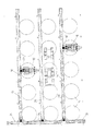
図2から明らかなように、サイロ14は平行な列をなして配置され、ここに示す実施形態では、等距離離れて立つ5基のサイロを有する3つの平行な列を形成する。コンベヤベルト20、21、22はサイロの列と平行であり、袋充填機で充填された袋18を、前記コンベヤベルトと垂直に配列されたコンベヤベルト24に搬送する。
【0014】
図1から明らかなように、コンベヤベルト20、21、22、24は、袋充填機16又はトラック32を移動させるのに要求される、必要な通過高さよりも上に配列される。袋充填機16の底領域で充填され、そして袋充填機を閉鎖させておく充填済みの袋は、本実施形態では袋充填機に直接連結されたエレベーター40によって袋充填機からコンベヤベルト20、21、22に搬送される。トラック32が、それを予め選択されたサイロ14の1つのサイロ出口の下で充填するために袋充填機16間を楽に進み、図1に示すように、トラック32を充填パイプライン34で適当なサイロ出口に連結することができる。
【0015】
図1の右側はサイロ出口に連結され、そして袋18を充填する袋充填機16を示し、袋をエレベーターによってコンベヤベルト20に搬送する。図1の左側は既にサイロから分離され且つ移動する準備が整った位置にある充填機16を示す。充填機を在来の仕方で移動させることができる。本発明の実施形態によれば、コンベヤベルトはもはや移動する袋充填機の道路内になく、その結果、袋充填機16を所望のサイロのそれぞれの充填開口に最短経路で割り当てることができる。
【0016】
ここに示していない変形の設計例では、エレベーターを充填機16と別々に配置し、そしてそれを望むときにのみ充填機に連結させても良い。
【図面の簡単な説明】
【図1】 1つの実施形態による本発明の設備の側面図である。
【図2】 図1による設備の平面図である。
【図3】 従来技術による設備の平面図である。
【図4】 図3の従来技術による設備の側面図である。
【符号の説明】
12 支柱
14 サイロ
16 袋充填機
18 袋
20 コンベヤベルト
21 コンベヤベルト
22 コンベヤベルト
24 コンベヤベルト
32 トラック
40 エレベーター[0001]
BACKGROUND OF THE INVENTION
The invention relates to an installation according to the preamble of
[0002]
[Prior art]
Such equipment already exists in the prior art. The configuration of the prior art equipment will be described with reference to FIGS. FIG. 3 is a plan view of the corresponding equipment, and FIG. 4 is a cross-sectional view thereof.
[0003]
The
[0004]
The
[0005]
[Problems to be solved by the invention]
The prior art equipment has the disadvantage that it is three stories and is therefore very large. The top floor level has a fixed silo, the bag filling machine can be moved at the middle floor level, and the truck can enter at the bottom floor level. In addition, the bag filling machine at the middle floor level cannot always be moved the shortest distance to the desired silo outlet because the corresponding conveyor belt is in the middle.
[0006]
Accordingly, it is an object of the present invention to allow pourable material to be loaded into at least one bag filling machine and / or at least one truck, and is relatively small, and a truck or bag filling machine is desired for each. It is to provide a facility that can be quickly moved to a silo outlet of a short route.
[0007]
[Means for Solving the Problems]
The present invention solves this problem associated with this type of equipment by combining additional features of the characterizing portion of
[0008]
Particular embodiments of the invention are subject to the dependent claims following the main claim.
[0009]
According to what has been described above, each filling machine should be assigned an elevator that is connected to it and can be moved with it.
[0010]
The elevator may be connected to the filling machine in such a way that its height is adjustable. Alternatively, each filling machine and its elevator may be moved separately.
[0011]
Other details and advantages are in accordance with one illustrated embodiment.
[0012]
DETAILED DESCRIPTION OF THE INVENTION
1 and 2 illustrate one embodiment of the present invention presented herein. The
[0013]
As is apparent from FIG. 2, the
[0014]
As is apparent from FIG. 1, the
[0015]
The right side of FIG. 1 is connected to the silo outlet and shows a
[0016]
In a variant design not shown here, the elevator may be arranged separately from the filling
[Brief description of the drawings]
FIG. 1 is a side view of an installation of the present invention according to one embodiment.
FIG. 2 is a plan view of the installation according to FIG.
FIG. 3 is a plan view of a facility according to the prior art.
4 is a side view of the prior art facility of FIG. 3;
[Explanation of symbols]
12
Claims (4)
前記少なくとも1つの袋充填機に割り当てられた前記少なくとも1つの中間コンベヤは、設備内を全体的に又は部分的に前後左右に移動可能なエレベーターとして設計され、前記エレベーターの排出端は、作業位置では、前記少なくとも1台の袋充填機及び前記少なくとも1台のトラックを同じ高さレベルで移動させるのに必要な要求通路高さよりも上に配列された前記コンベヤベルトの1つと一致する、前記設備。An apparatus for alternatively loading pourable material stored in a plurality of silos into at least one bag filling machine and at least one truck, the silo being firmly supported by struts; Can move at least one truck and / or at least one bag filling machine below the desired silo outlet and, following bag filling, remove the bag from the bag filling machine and through the facility. In the said equipment, which can be transferred to one of several conveyor belts via an intermediate conveyor which can be moved in whole or in part back and forth and left and right,
The at least one intermediate conveyor assigned to the at least one bag filling machine is designed as an elevator that can be moved forward and backward, left and right in the whole or part of the facility, and the discharge end of the elevator is at the working position. the matches one of the conveyor belts arranged above the required passage height required to move at least one of the bag filling machine and a track of said at least one at the same height level, said equipment.
Applications Claiming Priority (2)
| Application Number | Priority Date | Filing Date | Title |
|---|---|---|---|
| DE19831818:9 | 1998-07-15 | ||
| DE19831818A DE19831818C2 (en) | 1998-07-15 | 1998-07-15 | Silo system |
Publications (2)
| Publication Number | Publication Date |
|---|---|
| JP2000103497A JP2000103497A (en) | 2000-04-11 |
| JP4301645B2 true JP4301645B2 (en) | 2009-07-22 |
Family
ID=7874160
Family Applications (1)
| Application Number | Title | Priority Date | Filing Date |
|---|---|---|---|
| JP19857799A Expired - Fee Related JP4301645B2 (en) | 1998-07-15 | 1999-07-13 | Silo equipment |
Country Status (6)
| Country | Link |
|---|---|
| US (1) | US6186195B1 (en) |
| EP (1) | EP0972725B1 (en) |
| JP (1) | JP4301645B2 (en) |
| AT (1) | ATE222556T1 (en) |
| BR (1) | BR9902799A (en) |
| DE (2) | DE19831818C2 (en) |
Families Citing this family (10)
| Publication number | Priority date | Publication date | Assignee | Title |
|---|---|---|---|---|
| US6390152B1 (en) * | 2000-11-27 | 2002-05-21 | Aluminum Ladder Company | Modular bulk material handling station |
| DE20216866U1 (en) * | 2002-11-02 | 2004-03-11 | Haver & Boecker | Filling system for putting granular material into sacks or containers has framework on wheels carrying admission valve and weighing machine discharging into hopper and filling tube |
| US8528606B1 (en) | 2007-11-14 | 2013-09-10 | Michael J. Seiver | Apparatus and methods for filling containers with non-liquids |
| US9752389B2 (en) * | 2012-08-13 | 2017-09-05 | Schlumberger Technology Corporation | System and method for delivery of oilfield materials |
| US10633174B2 (en) | 2013-08-08 | 2020-04-28 | Schlumberger Technology Corporation | Mobile oilfield materialtransfer unit |
| US10150612B2 (en) | 2013-08-09 | 2018-12-11 | Schlumberger Technology Corporation | System and method for delivery of oilfield materials |
| US11453146B2 (en) | 2014-02-27 | 2022-09-27 | Schlumberger Technology Corporation | Hydration systems and methods |
| US11819810B2 (en) | 2014-02-27 | 2023-11-21 | Schlumberger Technology Corporation | Mixing apparatus with flush line and method |
| SG10201807799UA (en) * | 2018-09-10 | 2020-04-29 | Eng Soon Goh | Crash-resistant Bulk Fluid Cargo Distribution Terminal |
| CN112868399B (en) * | 2020-12-30 | 2022-12-02 | 望江县东方米业有限责任公司 | Rice storage unit |
Family Cites Families (3)
| Publication number | Priority date | Publication date | Assignee | Title |
|---|---|---|---|---|
| GB1349252A (en) * | 1972-03-23 | 1974-04-03 | Rawicki Dust Control | Roadside storage bunker |
| US3968626A (en) * | 1974-11-11 | 1976-07-13 | Hobbs Oliver K | Apparatus for bagging material |
| DE2830592A1 (en) * | 1978-07-12 | 1980-01-31 | Dieter Scheich | Proximity control of rail-bound transporter - with rigid structure for elastomer embedded magnetic field response system |
-
1998
- 1998-07-15 DE DE19831818A patent/DE19831818C2/en not_active Expired - Fee Related
-
1999
- 1999-06-05 AT AT99110817T patent/ATE222556T1/en not_active IP Right Cessation
- 1999-06-05 DE DE59902401T patent/DE59902401D1/en not_active Expired - Lifetime
- 1999-06-05 EP EP99110817A patent/EP0972725B1/en not_active Expired - Lifetime
- 1999-07-01 US US09/345,732 patent/US6186195B1/en not_active Expired - Lifetime
- 1999-07-13 JP JP19857799A patent/JP4301645B2/en not_active Expired - Fee Related
- 1999-07-15 BR BR9902799-2A patent/BR9902799A/en not_active IP Right Cessation
Also Published As
| Publication number | Publication date |
|---|---|
| DE19831818A1 (en) | 2000-02-17 |
| US6186195B1 (en) | 2001-02-13 |
| JP2000103497A (en) | 2000-04-11 |
| DE59902401D1 (en) | 2002-09-26 |
| ATE222556T1 (en) | 2002-09-15 |
| DE19831818C2 (en) | 2000-05-25 |
| BR9902799A (en) | 2000-02-22 |
| EP0972725A1 (en) | 2000-01-19 |
| EP0972725B1 (en) | 2002-08-21 |
Similar Documents
| Publication | Publication Date | Title |
|---|---|---|
| US8490774B2 (en) | Loading station for transport bags transported in an overhead conveyor system | |
| US4676050A (en) | Method and apparatus for transporting flexible packages, particularly flat bags, filled with pourable or flowable material to container filling stations | |
| JP4301645B2 (en) | Silo equipment | |
| US12077326B2 (en) | Apparatus and method for filling bulk materials into open bags | |
| US4603771A (en) | Sorting installation for piece goods | |
| US5567104A (en) | Apparatus for the transport and stocking of cigarettes | |
| US6672033B2 (en) | Air-filled packing cushion delivery system | |
| US3091903A (en) | Receptacle filling apparatus | |
| JP2009518257A (en) | Product shock absorber and method of operating the device | |
| CZ9803313A3 (en) | Filling apparatus for filling packages | |
| CN212531136U (en) | Bagged material car loader capable of feeding materials in wide and narrow range | |
| CN110386439B (en) | Sorting unloader and method for unloading and sorting packages provided in containers | |
| US2278730A (en) | Apparatus for discharging bins to conveyers | |
| CN101410302B (en) | Transporting arrangement | |
| JP3025242B2 (en) | Packing device and method | |
| KR19990029408A (en) | Apparatus for sorting or selectively collecting flat products individually transported by conveyors | |
| US3280725A (en) | Strapping machine and system | |
| CN108473146B (en) | Bulk material storage compartment | |
| US3209894A (en) | Conveyor | |
| JP7277474B2 (en) | Systems and equipment for loading, transporting and unloading fragile products | |
| US1825037A (en) | Conveying apparatus | |
| GB2050280A (en) | A bunker conveyor | |
| JPH10305922A (en) | Bag distributing device | |
| US2626094A (en) | Bag-filling machine with adjustably mounted article guide rails | |
| JPH0289795A (en) | Device for dividingly handling heterogeneous material |
Legal Events
| Date | Code | Title | Description |
|---|---|---|---|
| A621 | Written request for application examination |
Free format text: JAPANESE INTERMEDIATE CODE: A621 Effective date: 20060713 |
|
| A977 | Report on retrieval |
Free format text: JAPANESE INTERMEDIATE CODE: A971007 Effective date: 20080827 |
|
| A131 | Notification of reasons for refusal |
Free format text: JAPANESE INTERMEDIATE CODE: A131 Effective date: 20080901 |
|
| A521 | Request for written amendment filed |
Free format text: JAPANESE INTERMEDIATE CODE: A523 Effective date: 20081128 |
|
| TRDD | Decision of grant or rejection written | ||
| A01 | Written decision to grant a patent or to grant a registration (utility model) |
Free format text: JAPANESE INTERMEDIATE CODE: A01 Effective date: 20090413 |
|
| A01 | Written decision to grant a patent or to grant a registration (utility model) |
Free format text: JAPANESE INTERMEDIATE CODE: A01 |
|
| A61 | First payment of annual fees (during grant procedure) |
Free format text: JAPANESE INTERMEDIATE CODE: A61 Effective date: 20090421 |
|
| FPAY | Renewal fee payment (event date is renewal date of database) |
Free format text: PAYMENT UNTIL: 20120501 Year of fee payment: 3 |
|
| R150 | Certificate of patent or registration of utility model |
Free format text: JAPANESE INTERMEDIATE CODE: R150 |
|
| FPAY | Renewal fee payment (event date is renewal date of database) |
Free format text: PAYMENT UNTIL: 20130501 Year of fee payment: 4 |
|
| R250 | Receipt of annual fees |
Free format text: JAPANESE INTERMEDIATE CODE: R250 |
|
| R250 | Receipt of annual fees |
Free format text: JAPANESE INTERMEDIATE CODE: R250 |
|
| LAPS | Cancellation because of no payment of annual fees |