JP4301583B2 - Heated ink jet printer and method for forming heat sink member of head thereof - Google Patents
Heated ink jet printer and method for forming heat sink member of head thereof Download PDFInfo
- Publication number
- JP4301583B2 JP4301583B2 JP15487297A JP15487297A JP4301583B2 JP 4301583 B2 JP4301583 B2 JP 4301583B2 JP 15487297 A JP15487297 A JP 15487297A JP 15487297 A JP15487297 A JP 15487297A JP 4301583 B2 JP4301583 B2 JP 4301583B2
- Authority
- JP
- Japan
- Prior art keywords
- heat sink
- print head
- substrate
- ink
- film
- Prior art date
- Legal status (The legal status is an assumption and is not a legal conclusion. Google has not performed a legal analysis and makes no representation as to the accuracy of the status listed.)
- Expired - Fee Related
Links
- 238000000034 method Methods 0.000 title claims description 11
- ZCDOYSPFYFSLEW-UHFFFAOYSA-N chromate(2-) Chemical compound [O-][Cr]([O-])(=O)=O ZCDOYSPFYFSLEW-UHFFFAOYSA-N 0.000 claims description 41
- RYGMFSIKBFXOCR-UHFFFAOYSA-N Copper Chemical compound [Cu] RYGMFSIKBFXOCR-UHFFFAOYSA-N 0.000 claims description 30
- 239000010949 copper Substances 0.000 claims description 30
- 229910052802 copper Inorganic materials 0.000 claims description 29
- 239000000758 substrate Substances 0.000 claims description 26
- 238000007747 plating Methods 0.000 claims description 23
- 238000010438 heat treatment Methods 0.000 claims description 16
- 238000000576 coating method Methods 0.000 claims description 15
- 239000011248 coating agent Substances 0.000 claims description 13
- 229910052751 metal Inorganic materials 0.000 claims description 12
- 239000002184 metal Substances 0.000 claims description 12
- 239000003792 electrolyte Substances 0.000 claims description 7
- XLYOFNOQVPJJNP-UHFFFAOYSA-N water Substances O XLYOFNOQVPJJNP-UHFFFAOYSA-N 0.000 claims description 7
- 230000005684 electric field Effects 0.000 claims description 6
- KRVSOGSZCMJSLX-UHFFFAOYSA-L chromic acid Substances O[Cr](O)(=O)=O KRVSOGSZCMJSLX-UHFFFAOYSA-L 0.000 claims description 3
- 230000003628 erosive effect Effects 0.000 claims description 3
- AWJWCTOOIBYHON-UHFFFAOYSA-N furo[3,4-b]pyrazine-5,7-dione Chemical compound C1=CN=C2C(=O)OC(=O)C2=N1 AWJWCTOOIBYHON-UHFFFAOYSA-N 0.000 claims description 3
- WGLPBDUCMAPZCE-UHFFFAOYSA-N Trioxochromium Chemical compound O=[Cr](=O)=O WGLPBDUCMAPZCE-UHFFFAOYSA-N 0.000 claims description 2
- 229920000642 polymer Polymers 0.000 claims description 2
- 239000007788 liquid Substances 0.000 claims 6
- 229910000423 chromium oxide Inorganic materials 0.000 claims 1
- 229910000431 copper oxide Inorganic materials 0.000 claims 1
- 238000001035 drying Methods 0.000 claims 1
- 238000005530 etching Methods 0.000 claims 1
- 229920000592 inorganic polymer Polymers 0.000 claims 1
- 239000000976 ink Substances 0.000 description 30
- 230000007797 corrosion Effects 0.000 description 18
- 238000005260 corrosion Methods 0.000 description 18
- 239000010410 layer Substances 0.000 description 13
- 229910052725 zinc Inorganic materials 0.000 description 12
- 239000011701 zinc Substances 0.000 description 12
- HCHKCACWOHOZIP-UHFFFAOYSA-N Zinc Chemical compound [Zn] HCHKCACWOHOZIP-UHFFFAOYSA-N 0.000 description 11
- 238000007654 immersion Methods 0.000 description 10
- 238000005259 measurement Methods 0.000 description 9
- 238000002791 soaking Methods 0.000 description 7
- PXHVJJICTQNCMI-UHFFFAOYSA-N Nickel Chemical compound [Ni] PXHVJJICTQNCMI-UHFFFAOYSA-N 0.000 description 6
- 230000000694 effects Effects 0.000 description 6
- 238000011282 treatment Methods 0.000 description 6
- 238000004140 cleaning Methods 0.000 description 5
- 238000002161 passivation Methods 0.000 description 4
- 230000004888 barrier function Effects 0.000 description 3
- 239000000463 material Substances 0.000 description 3
- 229910052759 nickel Inorganic materials 0.000 description 3
- 235000012431 wafers Nutrition 0.000 description 3
- QGZKDVFQNNGYKY-UHFFFAOYSA-N Ammonia Chemical compound N QGZKDVFQNNGYKY-UHFFFAOYSA-N 0.000 description 2
- VYZAMTAEIAYCRO-UHFFFAOYSA-N Chromium Chemical compound [Cr] VYZAMTAEIAYCRO-UHFFFAOYSA-N 0.000 description 2
- FAPWRFPIFSIZLT-UHFFFAOYSA-M Sodium chloride Chemical compound [Na+].[Cl-] FAPWRFPIFSIZLT-UHFFFAOYSA-M 0.000 description 2
- 230000002378 acidificating effect Effects 0.000 description 2
- 239000000853 adhesive Substances 0.000 description 2
- 230000001070 adhesive effect Effects 0.000 description 2
- 238000013019 agitation Methods 0.000 description 2
- 229910000365 copper sulfate Inorganic materials 0.000 description 2
- ARUVKPQLZAKDPS-UHFFFAOYSA-L copper(II) sulfate Chemical compound [Cu+2].[O-][S+2]([O-])([O-])[O-] ARUVKPQLZAKDPS-UHFFFAOYSA-L 0.000 description 2
- XPPKVPWEQAFLFU-UHFFFAOYSA-J diphosphate(4-) Chemical compound [O-]P([O-])(=O)OP([O-])([O-])=O XPPKVPWEQAFLFU-UHFFFAOYSA-J 0.000 description 2
- 235000011180 diphosphates Nutrition 0.000 description 2
- 238000007598 dipping method Methods 0.000 description 2
- 238000002845 discoloration Methods 0.000 description 2
- 239000003574 free electron Substances 0.000 description 2
- 239000003906 humectant Substances 0.000 description 2
- 238000007641 inkjet printing Methods 0.000 description 2
- 239000012528 membrane Substances 0.000 description 2
- 238000005406 washing Methods 0.000 description 2
- 239000004593 Epoxy Substances 0.000 description 1
- 239000004642 Polyimide Substances 0.000 description 1
- BQCADISMDOOEFD-UHFFFAOYSA-N Silver Chemical compound [Ag] BQCADISMDOOEFD-UHFFFAOYSA-N 0.000 description 1
- PMZURENOXWZQFD-UHFFFAOYSA-L Sodium Sulfate Chemical compound [Na+].[Na+].[O-]S([O-])(=O)=O PMZURENOXWZQFD-UHFFFAOYSA-L 0.000 description 1
- 125000003277 amino group Chemical group 0.000 description 1
- 229910021529 ammonia Inorganic materials 0.000 description 1
- 230000003115 biocidal effect Effects 0.000 description 1
- 239000003139 biocide Substances 0.000 description 1
- 229940075397 calomel Drugs 0.000 description 1
- 238000004532 chromating Methods 0.000 description 1
- 229910052804 chromium Inorganic materials 0.000 description 1
- 239000011651 chromium Substances 0.000 description 1
- 229940117975 chromium trioxide Drugs 0.000 description 1
- GAMDZJFZMJECOS-UHFFFAOYSA-N chromium(6+);oxygen(2-) Chemical compound [O-2].[O-2].[O-2].[Cr+6] GAMDZJFZMJECOS-UHFFFAOYSA-N 0.000 description 1
- 239000011247 coating layer Substances 0.000 description 1
- DOBRDRYODQBAMW-UHFFFAOYSA-N copper(i) cyanide Chemical compound [Cu+].N#[C-] DOBRDRYODQBAMW-UHFFFAOYSA-N 0.000 description 1
- 239000006184 cosolvent Substances 0.000 description 1
- 239000008367 deionised water Substances 0.000 description 1
- 229910021641 deionized water Inorganic materials 0.000 description 1
- 230000008021 deposition Effects 0.000 description 1
- 238000004512 die casting Methods 0.000 description 1
- 238000007607 die coating method Methods 0.000 description 1
- ZOMNIUBKTOKEHS-UHFFFAOYSA-L dimercury dichloride Chemical compound Cl[Hg][Hg]Cl ZOMNIUBKTOKEHS-UHFFFAOYSA-L 0.000 description 1
- 125000002887 hydroxy group Chemical group [H]O* 0.000 description 1
- 125000001841 imino group Chemical group [H]N=* 0.000 description 1
- 238000009413 insulation Methods 0.000 description 1
- 150000002500 ions Chemical class 0.000 description 1
- 238000000059 patterning Methods 0.000 description 1
- 230000010287 polarization Effects 0.000 description 1
- 229920001721 polyimide Polymers 0.000 description 1
- 238000002360 preparation method Methods 0.000 description 1
- 238000007639 printing Methods 0.000 description 1
- 239000011241 protective layer Substances 0.000 description 1
- 239000001044 red dye Substances 0.000 description 1
- 238000000926 separation method Methods 0.000 description 1
- 229910052710 silicon Inorganic materials 0.000 description 1
- 239000010703 silicon Substances 0.000 description 1
- 229910052709 silver Inorganic materials 0.000 description 1
- 239000004332 silver Substances 0.000 description 1
- 239000011780 sodium chloride Substances 0.000 description 1
- 229910052938 sodium sulfate Inorganic materials 0.000 description 1
- 235000011152 sodium sulphate Nutrition 0.000 description 1
- 239000002904 solvent Substances 0.000 description 1
- 238000003756 stirring Methods 0.000 description 1
- 239000000126 substance Substances 0.000 description 1
- 238000010998 test method Methods 0.000 description 1
- 125000003396 thiol group Chemical group [H]S* 0.000 description 1
- 238000011179 visual inspection Methods 0.000 description 1
- 150000003751 zinc Chemical class 0.000 description 1
Images

Classifications
-
- B—PERFORMING OPERATIONS; TRANSPORTING
- B41—PRINTING; LINING MACHINES; TYPEWRITERS; STAMPS
- B41J—TYPEWRITERS; SELECTIVE PRINTING MECHANISMS, i.e. MECHANISMS PRINTING OTHERWISE THAN FROM A FORME; CORRECTION OF TYPOGRAPHICAL ERRORS
- B41J2/00—Typewriters or selective printing mechanisms characterised by the printing or marking process for which they are designed
- B41J2/005—Typewriters or selective printing mechanisms characterised by the printing or marking process for which they are designed characterised by bringing liquid or particles selectively into contact with a printing material
- B41J2/01—Ink jet
- B41J2/135—Nozzles
- B41J2/16—Production of nozzles
- B41J2/1601—Production of bubble jet print heads
- B41J2/1604—Production of bubble jet print heads of the edge shooter type
-
- B—PERFORMING OPERATIONS; TRANSPORTING
- B41—PRINTING; LINING MACHINES; TYPEWRITERS; STAMPS
- B41J—TYPEWRITERS; SELECTIVE PRINTING MECHANISMS, i.e. MECHANISMS PRINTING OTHERWISE THAN FROM A FORME; CORRECTION OF TYPOGRAPHICAL ERRORS
- B41J2/00—Typewriters or selective printing mechanisms characterised by the printing or marking process for which they are designed
- B41J2/005—Typewriters or selective printing mechanisms characterised by the printing or marking process for which they are designed characterised by bringing liquid or particles selectively into contact with a printing material
- B41J2/01—Ink jet
- B41J2/135—Nozzles
- B41J2/14—Structure thereof only for on-demand ink jet heads
- B41J2/14016—Structure of bubble jet print heads
- B41J2/14088—Structure of heating means
- B41J2/14112—Resistive element
- B41J2/14129—Layer structure
-
- B—PERFORMING OPERATIONS; TRANSPORTING
- B41—PRINTING; LINING MACHINES; TYPEWRITERS; STAMPS
- B41J—TYPEWRITERS; SELECTIVE PRINTING MECHANISMS, i.e. MECHANISMS PRINTING OTHERWISE THAN FROM A FORME; CORRECTION OF TYPOGRAPHICAL ERRORS
- B41J2/00—Typewriters or selective printing mechanisms characterised by the printing or marking process for which they are designed
- B41J2/005—Typewriters or selective printing mechanisms characterised by the printing or marking process for which they are designed characterised by bringing liquid or particles selectively into contact with a printing material
- B41J2/01—Ink jet
- B41J2/135—Nozzles
- B41J2/16—Production of nozzles
- B41J2/1621—Manufacturing processes
- B41J2/1623—Manufacturing processes bonding and adhesion
-
- B—PERFORMING OPERATIONS; TRANSPORTING
- B41—PRINTING; LINING MACHINES; TYPEWRITERS; STAMPS
- B41J—TYPEWRITERS; SELECTIVE PRINTING MECHANISMS, i.e. MECHANISMS PRINTING OTHERWISE THAN FROM A FORME; CORRECTION OF TYPOGRAPHICAL ERRORS
- B41J2/00—Typewriters or selective printing mechanisms characterised by the printing or marking process for which they are designed
- B41J2/005—Typewriters or selective printing mechanisms characterised by the printing or marking process for which they are designed characterised by bringing liquid or particles selectively into contact with a printing material
- B41J2/01—Ink jet
- B41J2/135—Nozzles
- B41J2/16—Production of nozzles
- B41J2/1621—Manufacturing processes
- B41J2/1626—Manufacturing processes etching
-
- B—PERFORMING OPERATIONS; TRANSPORTING
- B41—PRINTING; LINING MACHINES; TYPEWRITERS; STAMPS
- B41J—TYPEWRITERS; SELECTIVE PRINTING MECHANISMS, i.e. MECHANISMS PRINTING OTHERWISE THAN FROM A FORME; CORRECTION OF TYPOGRAPHICAL ERRORS
- B41J2/00—Typewriters or selective printing mechanisms characterised by the printing or marking process for which they are designed
- B41J2/005—Typewriters or selective printing mechanisms characterised by the printing or marking process for which they are designed characterised by bringing liquid or particles selectively into contact with a printing material
- B41J2/01—Ink jet
- B41J2/135—Nozzles
- B41J2/16—Production of nozzles
- B41J2/1621—Manufacturing processes
- B41J2/1631—Manufacturing processes photolithography
-
- B—PERFORMING OPERATIONS; TRANSPORTING
- B41—PRINTING; LINING MACHINES; TYPEWRITERS; STAMPS
- B41J—TYPEWRITERS; SELECTIVE PRINTING MECHANISMS, i.e. MECHANISMS PRINTING OTHERWISE THAN FROM A FORME; CORRECTION OF TYPOGRAPHICAL ERRORS
- B41J2/00—Typewriters or selective printing mechanisms characterised by the printing or marking process for which they are designed
- B41J2/005—Typewriters or selective printing mechanisms characterised by the printing or marking process for which they are designed characterised by bringing liquid or particles selectively into contact with a printing material
- B41J2/01—Ink jet
- B41J2/135—Nozzles
- B41J2/16—Production of nozzles
- B41J2/1621—Manufacturing processes
- B41J2/1635—Manufacturing processes dividing the wafer into individual chips
-
- B—PERFORMING OPERATIONS; TRANSPORTING
- B41—PRINTING; LINING MACHINES; TYPEWRITERS; STAMPS
- B41J—TYPEWRITERS; SELECTIVE PRINTING MECHANISMS, i.e. MECHANISMS PRINTING OTHERWISE THAN FROM A FORME; CORRECTION OF TYPOGRAPHICAL ERRORS
- B41J2/00—Typewriters or selective printing mechanisms characterised by the printing or marking process for which they are designed
- B41J2/005—Typewriters or selective printing mechanisms characterised by the printing or marking process for which they are designed characterised by bringing liquid or particles selectively into contact with a printing material
- B41J2/01—Ink jet
- B41J2/135—Nozzles
- B41J2/16—Production of nozzles
- B41J2/1621—Manufacturing processes
- B41J2/164—Manufacturing processes thin film formation
- B41J2/1643—Manufacturing processes thin film formation thin film formation by plating
-
- Y—GENERAL TAGGING OF NEW TECHNOLOGICAL DEVELOPMENTS; GENERAL TAGGING OF CROSS-SECTIONAL TECHNOLOGIES SPANNING OVER SEVERAL SECTIONS OF THE IPC; TECHNICAL SUBJECTS COVERED BY FORMER USPC CROSS-REFERENCE ART COLLECTIONS [XRACs] AND DIGESTS
- Y10—TECHNICAL SUBJECTS COVERED BY FORMER USPC
- Y10T—TECHNICAL SUBJECTS COVERED BY FORMER US CLASSIFICATION
- Y10T29/00—Metal working
- Y10T29/49—Method of mechanical manufacture
- Y10T29/49401—Fluid pattern dispersing device making, e.g., ink jet
Description
【0001】
【発明の属する技術分野】
本発明は、インクジェットプリント装置であって、エネルギーを利用し、プリントヘッドの内部に形成されるチャネルに保持されるインク滴を、オリフィスから記録媒体に噴射する装置に関する。特に、本発明は、高pHインクが、プリントヘッドのヒートシンク部に与える腐食の影響に耐える改善された被覆膜を持つインクジェットプリントヘッドに関する。
【0002】
【従来の技術】
高pHインクの腐食の影響を受けやすいプリントヘッドの領域は、加熱インクジェットプリンタのダイの搭載に使用されるヒートシンクである。ヒートシンクは、一般的には、亜鉛のような熱伝導率の良い金属で構成される。この亜鉛は他の金属で被覆され、この被覆はプリントヘッドダイに直接接着される。一般的には、亜鉛ダイカストは、防食性を備える。これは、一連のメッキ/処理ステップにより行われ、最初に高均一電着性シアン化銅、またはピロリン酸塩の槽において銅の薄い被覆を付けることから開始し、次いで、酸性銅硫酸塩電解液において、要求される銅厚にメッキを行う。最終の被覆は用途に応じ選ばれる。海や工場の環境において、一般的には、ハードウェアはガルバニック防食、すなわち、犠牲防食を与える被覆の組み合わせにより処理される。この防食は、光沢ニッケルとクロム金属の層などから得られる。
【0003】
【発明が解決しようとする課題】
亜鉛ダイの被覆に選ばれる金属の問題は、錯体(complex)が、いずれかの自由電子対を持つ化学種(species)から形成されることである。水、アンモニア、アミノ群、イミノ群、ヒドロキシル群、チオール群は、自由電子対を持つ錯体の例である。従って、1またはそれ以上の、このような群の物質を含むインクは、ヒートシンクに接触するニッケルまたは銅の被覆層を容易に浸食する。これは、通常の印刷において常に発生する。結果的に、ヒートシンクは時間とともに浸食される。ヒートシンクの外観の損傷を別としても、このような腐食の重大な問題は、基板からダイの分離が起こることである。
【0004】
他の同様な腐食の原因には、湿気の存在するニッケルと亜鉛のような被覆金属の間の電気反応がある。
【0005】
【課題を解決するための手段】
本発明の目的は、耐インク障壁被覆を、プリントヘッドヒートシンク上に形成し、インクによる腐食の影響を防ぐインクジェットプリント装置を提供することである。
【0006】
本発明の他の目的は、インクの中のイオンおよび分子の化学種による化学腐食に不活性の保護層を提供することである。
【0007】
さらに他の目的は、加熱インクジェットプリントヘッドの有効なpH範囲を広げることである。
【0008】
これら、および他の目的は、亜鉛ヒートシンクに銅メッキを行い、メッキ上に高分子クロメート障壁膜を形成することにより実現される。クロメート膜は、浸せき処理、または陰極クロメート処理のいずれかにより形成される。銅メッキされ、その表面に形成されるクロメート障壁膜を持つヒートシンクは、インクの腐食の影響に対し大きな耐性を示し、プリントヘッドに接着されると、接着面に強い接着を与える。
【0009】
特に、本発明は、記録媒体にインクを噴射する加熱インクジェットプリンタに関し、この加熱インクジェットプリンタは、インクを保持する少なくとも一個のチャネルを含むプリントヘッドと、記録媒体にインクを噴射する少なくとも一個のノズルと、チャネルの中のインクを選択的に加熱し、チャネルの中のインクをノズルから噴射させる加熱手段と、プリントヘッドが接着される表面を持つヒートシンクであって、このヒートシンクが、基板面に形成される薄い銅メッキ膜を持つ金属基板と、銅メッキ膜の上に重ねられる薄いクロメート膜を持ち、このクロメート膜の表面にプリントヘッドが接着される、ヒートシンクと、を含む。
【0010】
また、本発明は、改善された耐インク腐食性を持つ少なくとも一個の表面を持つヒートシンク部材を形成する方法に関し、この方法は、
a)金属基板の表面に銅メッキを行い、0.0004から0.0007インチまでの間の厚さを持つ銅メッキ膜を形成し、
b)クロム酸と水の電解液槽を用意し、この槽は、中に離して入れられる一対の陽極を持ち、
c)メッキされた基板を槽に浸し、薄い高分子クロメート膜を形成するのに十分な時間、陽極に電界を加え、
d)槽から陰極クロメート膜が形成されたヒートシンクを取り出し、
e)ヒートシンクを乾燥する、
ステップを含む。
【0011】
【発明の実施の形態】
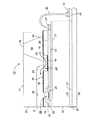
本発明は、全ての開示がここに参照され取り入れられている、ホーキンス他の米国再発行特許第32,572号、ホーキンス他の米国特許第5,010,355号、フィッシャ他の米国特許第4,851,371号、バローラの米国特許第5,297,336号に開示されている型の加熱インクジェットプリンタと関連させ説明される。本発明は、後で見られるように、特別な用途と異なる型のプリントヘッド構造を持つことが理解される。上記特許に開示されているように、加熱インクジェットプリントヘッドは、バッチで製造される。異方性腐食の行われたチャネルウェーハを、加熱ウェーハに合わせ、接着し、次いで、切断し、接着されたウェーハを個々のプリントヘッドに分離する。次いで、プリントヘッドをヒートシンクに接着し、さらにこのヒートシンクに、プリントヘッドに対する電気接続部を搭載するドーターボードを接着する。図1は、プリントヘッドの断面図を示し、このプリントヘッドは、本発明の原理に従う耐インク被覆により保護されるヒートシンクを持つ。プリントヘッド10は、異方性腐食の行われたチャネルプレート11を含み、このチャネルプレート11は、加熱プレート12に合わせられ、接着される。プレート12の表面のプリントヘッドは、銀エポキシにより、ヒートシンク35に接着される。ヒートシンク35は、一実施形態では、亜鉛基板32、銅メッキ膜33、以下に述べる技術により付着される高分子クロメート膜34を含む。同様に、ヒートシンク35の上に、電極13を持つドーターボード20が搭載される。電極13には、(図示されていない)駆動回路と電源が接続される。チャネルプレート11は、開端が注入口15となる腐食貫通された容器14と、中に異方性腐食の行われた複数のチャネル16を持つ。チャネル16の端は、ノズル面29に開き、傾斜端21で終る。チャネルの開端は、ノズル8として機能する。加熱プレートは、加熱素子25の列と、アドレス電極22を持ち、このアドレス電極22は、加熱プレート12のチャネル形プレートに面する表面に形成される。加熱素子と電極は、絶縁層27の上に形成され、別の絶縁層28により保護される。好ましい実施形態においては、厚膜絶縁層18は、加熱プレートとチャネル形プレートの間に挟み込まれる10ミクロンの厚さの感光ポリイミドである。層18には、パターンが形成され、保護され、加熱素子が露光され、これにより加熱素子が独立した穴26に配置され、容器14とインクチャネル16の間に、インクのバイパスとなる穴24が形成される。また、層18には、電極接着端子31を露光するパターンが形成される。パターン形成のステップに続き、層18は保護される。インクはこのようにして、矢印23で示されるように容器14からチャネル21の閉端を回りチャネル16に流れる。端子31は、接続線30によりドーターボード電極13に接続される。異方性腐食の行われたチャネル16は、三角の断面領域を持ち、ノズル表面29のノズルを囲む材料に、三角形ノズルの二方の側にはシリコンが使用され、第三の側には厚膜層材料の層が使用される。
【0012】
通常プリントモードで膜34が無いときのインクは、銅メッキ膜33を腐食し、ヒートシンクのプリントヘッドへの接着に徐々に影響を与える。しかし、本発明に従えば、クロメート膜34は、強固な、また安定したヒートシンク被覆を与える。このヒートシンク被覆は大きな耐インク腐食性を与え、プリントヘッドのヒートシンクへの接着を保持する。
【0013】
クロメート被覆は、浸せき処理、または陰極クロメート処理のいずれかにより、銅メッキされたヒートシンク面に形成される。各処理の例が図1と図2に示される。
【0014】
例I−浸せき
亜鉛ダイカスト32に銅メッキ処理が行われ、表面に銅の膜33が形成される。膜33は、ピロリン酸塩槽の銅の最初の付着と、続いて酸性銅硫酸塩電解液を使用し、約0.0006インチの最終メッキ厚にメッキされるものからなる。浸せき槽には、3g/lのクロム三酸化物(chromium trioxide)を脱イオン水に含み、大気温度において作用するものが使用される。銅メッキ亜鉛被覆は、槽の中で約30秒静止され行われ、銅とクロムの薄い酸化層(クロメート膜34)が形成される。一般的な厚さは、50から500オングストロームの範囲である。次いでヒートシンク35は取り出され、洗浄され、90℃でオーブン乾燥されるか、または洗浄されることなく単に90℃の温度で乾燥される。
【0015】
例II
銅膜33は例Iと同様に亜鉛基板32の表面に形成される。例Iと同様に同じH 2 CrO 4 槽が用意される。膜34は、次の陰極クロメート処理により形成される。
【0016】
a)槽と同じ容器の中に、寸法が安定している一対の陽極(好ましくは鉛)が浸される。
【0017】
b)銅メッキされたヒートシンクが槽に浸せきされる。
【0018】
c)電極が30ボルト直流電力供給端子に接続される。ヒートシンクは陰極であり、負の端子に接続される。
【0019】
d)ヒートシンクは約30秒間、クロメート膜34が形成されるまで浸せきされる。
【0020】
e)印加電圧が停止され、ヒートシンクが槽から取り出される。
【0021】
f)次いで、ヒートシンクは例Iと同様に乾燥される。
【0022】
比較結果
例Iと例IIのクロメートで不動態化された銅メッキヒートシンクのインク腐食の減少(不動態化)は、開回路腐食電位(open circuit corrosion potential(OCP))試験法により測定された。これは、各プロセスにより造られた三個のサンプルについて、二個の銅メッキされたコントロールサンプルと対比して実施された。
【0023】
二種類目の試験は、温度を上げた多種類のインクに長時間浸せきした後、ヒートシンクのプリントヘッドに対する剪断強さを測定し行われた。
【0024】
腐食試験
開回路腐食電位(OCP)電圧測定は、標準カロメル電極(standard calomel electrode(SCE))を基準にし行われる。表1の三欄、四欄、五欄の負数は、ヒートシンクの不動態化を示す。表1は、浸せき(例I)処理と陰極(例II)処理により形成された二組のサンプルの比較結果を示す。コントロールグループのサンプル(銅メッキヒートシンクのみ)は、対照のために試験される。ヒートシンクのサンプルの試験は、浸せき後、5秒と60秒と、攪拌ステップとともに60秒で行われる第三の測定を加え行われる。槽から取り出した後、サンプルの洗浄の有無による効果について、また、電圧を加え、または加えないで槽に入れ/出す陰極処理の効果について、付加的に試験が行われる。二組のサンプルが連続する日に用意される。用意した日にベーキングした後、室温に冷却し直ちにOCPが測定される。全てのサンプルは、10%重量の硫酸ナトリウムに15秒浸せきし清浄され、次いでタップ(tap)とDl水洗浄が行われ、吹き乾燥が行われ、その後、5分間、90℃でベーキングされる。OCP対SCEの測定は、pHがHclで3%に調整された、3%重量のNaCl、0.2%CuSO4.5H2Oの中で行われる。二組目の測定は、全てのサンプルについて三日目に行われる。従って、この時点での第一組のサンプルは研究室の大気に二日間曝され、第二組は一日間曝されていることになる。三個の測定が記録される。サンプルが電解液に入れられると、OCPは急激に変化し、5秒後に安定し始め、この時点で第一の測定が記録される。第二の測定は、さらに55秒後、静止した状態で記録される。60秒後の記録の直後、電解液が攪拌され、第三の記録がとられる。60秒と攪拌読み取りのみが重要であると考えてもよい。60秒測定は不動態化率を示す。60秒と攪拌読み取りの差は、混成電位における分極を示す。
【0025】
サンプル1とサンプル6はコントロールサンプルであり、サンプル2とサンプル7は、浸せきと洗浄を行い形成されるクロメートヒートシンクであり、サンプル3とサンプル8は、浸せきを行い、洗浄は行わないで形成されるクロメートヒートシンクであり、サンプル4は、洗浄を行い、浸せき後、電界が加えられる陰極クロメートヒートシンクであり、サンプル5は、洗浄は行わず、浸せき後、電界が加えられる陰極クロメートヒートシンクであり、サンプル9は、洗浄を行い、浸せきと取り出し時、電界が加えられる陰極クロメートヒートシンクであり、サンプル10は、洗浄を行わないで、浸せきと取り出し時、電界が加えられる陰極クロメートヒートシンクである。この結果、次の結論が得られる。
【0026】
1.陰極クロメート処理は、大きな不動態化と永続する接着面を与え、従って、浸せきクロメート処理ヒートシンク、またはコントロール(銅メッキのみ)ヒートシンクのいずれよりも、大きな耐インク腐食性を持つ。
【0027】
2.浸せきクロメート処理ヒートシンクは、コントロールよりも大きな不動態化接着面を与えた。
【0028】
3.電圧を加えながらの槽への入れ/出しは、不動態に対する明らかな効果を持たない。
【0029】
4.陰極クロメートサンプルの洗浄は、洗浄しないサンプルに比べ不動態に少し減少が見られる。
【0030】
サンプルの外観検査は、上の測定を裏付けている。サンプル1とサンプル6(コントロール)、サンプル2、サンプル3、サンプル7(洗浄する浸せきクロメート)は、研究室大気において六日後、残留変色を示した。陰極クロメートのサンプル4、サンプル5、サンプル9、サンプル10は、研究室大気において六日後、変色を示さなかった。
【0031】
【表1】

ダイ接着剪断試験は、プリントヘッド10(図1)を、銅メッキ膜33のみ(サンプル1)を持つヒートシンクと、浸せきを行い、膜33の上に陰極クロメート膜34を重ねたヒートシンクに接着し行われる。次いで、プリントヘッド/ヒートシンク組立は、黒色水性インクに浸せきされる。このインクは、全体で約77%重量の水と、13.6%重量の黒と赤の染料の混合と、全体で約9.4%重量の助溶剤(Cosolvent)/湿潤剤(Humectant)/殺生物剤(Biocide)、噴射助成剤(Jetting Aid)を含む。インク溶剤は、約pH=7.43、粘度1.32cps、表面張力53.8ダイン/cmである。サンプルは取り出され、次いで剪断試験にかけられ、ヒートシンクがプリントヘッドから分離する点の剪断値/ポンドが求められる。結果が表2に示される。ポンドで表される平均剪断値が3欄と5欄に示される。試験は0.050インチ/分の速度で行われる。次の観察結果が得られる。
【0032】
1.耐剪断力を最も良く示す構造(従って、プリントヘッドのヒートシンクへの接着を最も良く保持する)構造は、洗浄を行う、陰極クロメートサンプルである。
【0033】
【表2】
【0034】
3.浸せきと陰極の双方のクロメート構造は、処理されない、銅メッキのみのヒートシンクに比べ優れた剪断接着を与える。
【図面の簡単な説明】
【図1】 銅メッキされたヒートシンクの表面に形成される高分子クロメート耐インク被覆膜を持つヒートシンクを示す加熱インクジェットプリンタの拡大断面図である。
【図2】 図1の耐インク膜の形成に使用される2種類の処理の流れ図である。
【符号の説明】
8 ノズル、10 プリントヘッド、11 チャネルプレート、12 加熱プレート、13 電極、14 容器、15 注入口、16 チャネル、18 厚膜絶縁層、20 ドーターボード、21 傾斜端、22 アドレス電極、24 インク側路穴、25 加熱素子、26 穴、27 絶縁層、28 絶縁層、29 ノズル面、30 接続線、31 電極接着端子、32 亜鉛基板、33 銅メッキ膜、34 クロメート膜、35 ヒートシンク。[0001]
BACKGROUND OF THE INVENTION
The present invention relates to an inkjet printing apparatus that uses energy to eject ink droplets held in a channel formed inside a print head from a orifice onto a recording medium. In particular, the present invention relates to an inkjet printhead having an improved coating that resists the corrosion effects of high pH ink on the heat sink of the printhead.
[0002]
[Prior art]
An area of the print head that is susceptible to high pH ink corrosion is the heat sink used to mount the die of a heated inkjet printer. The heat sink is generally made of a metal having good thermal conductivity such as zinc. This zinc is coated with another metal and this coating is bonded directly to the printhead die. In general, zinc die-casting has corrosion resistance. This is done by a series of plating / processing steps, starting with applying a thin coating of copper first in a highly homogeneous electrodeposited copper cyanide or pyrophosphate bath and then an acidic copper sulfate electrolyte. , Plating is performed to the required copper thickness. The final coating is chosen according to the application. In a marine or factory environment, the hardware is typically treated with a galvanic protection, ie a combination of coatings that provide sacrificial protection. This anticorrosion is obtained from a layer of bright nickel and chromium metal.
[0003]
[Problems to be solved by the invention]
The problem with the metal chosen for the zinc die coating is that the complex is formed from species with any free electron pair. Water, ammonia, amino group, imino group, hydroxyl group and thiol group are examples of complexes having free electron pairs. Thus, an ink comprising one or more such groups of materials readily erodes the nickel or copper coating layer that contacts the heat sink. This always occurs in normal printing. As a result, the heat sink erodes over time. Apart from damage to the appearance of the heat sink, a significant problem with such corrosion is die separation from the substrate.
[0004]
Another source of similar corrosion is the electrical reaction between the nickel and zinc coatings in the presence of moisture.
[0005]
[Means for Solving the Problems]
It is an object of the present invention to provide an ink jet printing apparatus in which an ink resistant barrier coating is formed on a print head heat sink to prevent ink corrosion effects.
[0006]
It is another object of the present invention to provide a protective layer that is inert to chemical corrosion by ions and molecular species in the ink.
[0007]
Yet another object is to extend the effective pH range of heated inkjet printheads.
[0008]
These and other objects are achieved by copper plating a zinc heat sink and forming a polymeric chromate barrier film on the plating. The chromate film is formed by either immersion treatment or cathodic chromate treatment. A heat sink that is copper plated and has a chromate barrier film formed on its surface is highly resistant to the effects of ink corrosion and provides a strong bond to the bond surface when bonded to a printhead.
[0009]
In particular, the present invention relates to a heated inkjet printer that ejects ink onto a recording medium, the heated inkjet printer including a printhead that includes at least one channel that holds ink, and at least one nozzle that ejects ink onto the recording medium. A heating means for selectively heating the ink in the channel and ejecting the ink in the channel from the nozzle, and a heat sink having a surface to which the print head is bonded, and the heat sink is formed on the substrate surface A metal substrate having a thin copper plating film, and a heat sink having a thin chromate film overlying the copper plating film and having a print head bonded to the surface of the chromate film.
[0010]
The present invention also relates to a method of forming a heat sink member having at least one surface with improved ink corrosion resistance, the method comprising:
a) performing copper plating on the surface of the metal substrate to form a copper plating film having a thickness between 0.0004 and 0.0007 inches;
b) Prepare an electrolyte bath of chromic acid and water, this bath has a pair of anodes that are placed inside,
c) soaking the plated substrate in a bath and applying an electric field to the anode for a time sufficient to form a thin polymer chromate film;
d) Remove the heat sink on which the cathode chromate film is formed from the tank,
e) Dry the heat sink,
Includes steps.
[0011]
DETAILED DESCRIPTION OF THE INVENTION
The present invention includes Hawkins et al., U.S. Reissue Patent No. 32,572, Hawkins et al. U.S. Pat.No. 5,010,355, Fisher et al. U.S. Pat. This is described in connection with a heated ink jet printer of the type disclosed in US Pat. No. 5,297,336. It will be appreciated that the present invention has a different type of printhead structure for special applications, as will be seen later. As disclosed in the above patent, heated inkjet printheads are manufactured in batches. Channel wafers that have been subjected to anisotropic erosion are aligned and bonded to heated wafers, and then cut, separating the bonded wafers into individual printheads. Next, the print head is bonded to a heat sink, and a daughter board for mounting an electrical connection to the print head is bonded to the heat sink. FIG. 1 shows a cross-sectional view of a printhead that has a heat sink that is protected by an ink resistant coating in accordance with the principles of the present invention. The
[0012]
Ink in the absence of the
[0013]
The chromate coating is formed on the copper-plated heat sink surface by either dipping or cathodic chromating. Examples of each process are shown in FIGS.
[0014]
Example I-Immersion A zinc plating process is performed on the zinc die cast 32 to form a
[0015]
Example II
The
[0016]
a) A pair of anodes (preferably lead) of stable dimensions are immersed in the same container as the tank.
[0017]
b) A copper-plated heat sink is immersed in the bath.
[0018]
c) The electrode is connected to a 30 volt DC power supply terminal. The heat sink is a cathode and is connected to the negative terminal.
[0019]
d) The heat sink is immersed for about 30 seconds until the
[0020]
e) The applied voltage is stopped and the heat sink is removed from the bath.
[0021]
f) The heat sink is then dried as in Example I.
[0022]
Results of comparison The reduction (passivation) of ink corrosion in the chromated passivated copper-plated heat sinks of Examples I and II was determined by the open circuit corrosion potential (OCP) test method. Measured. This was done for the three samples made by each process in contrast to the two copper plated control samples.
[0023]
The second type of test was carried out by measuring the shear strength of the heat sink against the print head after soaking for a long time in various types of inks at elevated temperatures.
[0024]
Corrosion test Open circuit corrosion potential (OCP) voltage measurements are made with reference to a standard calomel electrode (SCE). The negative numbers in columns 3, 4 and 5 in Table 1 indicate heat sink passivation. Table 1 shows the results of a comparison of two sets of samples formed by immersion (Example I) and cathode (Example II) treatments. A control group sample (copper plated heat sink only) is tested for control. The heat sink sample is tested for 5 seconds and 60 seconds after soaking, with a third measurement performed at 60 seconds with a stirring step. After removal from the cell, additional tests are performed on the effect of whether the sample is washed or not and on the effect of the cathodic treatment with or without application of voltage. Two sets of samples are prepared on consecutive days. After baking on the day of preparation, it is cooled to room temperature and OCP is measured immediately. All samples are cleaned by dipping in 10% sodium sulfate for 15 seconds, followed by a tap and Dl water wash, blown dry, and then baked at 90 ° C. for 5 minutes. OCP vs. SCE measurements were made with 3% NaCl, 0.2% CuSO 4 .3, pH adjusted to 3% with Hcl. Performed in 5H 2 O. The second set of measurements is taken on the third day for all samples. Thus, the first set of samples at this point is exposed to the laboratory atmosphere for two days and the second set is exposed for one day. Three measurements are recorded. As the sample is placed in the electrolyte, the OCP changes rapidly and begins to stabilize after 5 seconds, at which point the first measurement is recorded. The second measurement is recorded still after another 55 seconds. Immediately after the recording after 60 seconds, the electrolyte is stirred and a third recording is taken. Only 60 seconds and agitation reading may be considered important. The 60 second measurement indicates the passivation rate. The difference between 60 seconds and the agitation reading indicates the polarization at the hybrid potential.
[0025]
Sample 1 and Sample 6 are control samples, Sample 2 and Sample 7 are chromate heat sinks formed by immersion and cleaning, and
[0026]
1. Cathodic chromate treatment provides great passivation and a permanent adhesive surface and thus has greater ink corrosion resistance than either an immersion chromate heat sink or a control (copper plating only) heat sink.
[0027]
2. The immersion chromated heat sink provided a passivated adhesive surface greater than the control.
[0028]
3. Putting in / out of the bath while applying voltage has no obvious effect on passivity.
[0029]
4). Cleaning the cathodic chromate sample shows a slight reduction in passivity compared to the unwashed sample.
[0030]
Sample visual inspection confirms the above measurements. Samples 1 and 6 (control), Sample 2, Sample 3, and Sample 7 (soaked chromate to be washed) showed residual discoloration after 6 days in the laboratory atmosphere. Cathodic chromate Sample 4, Sample 5, Sample 9, and
[0031]
[Table 1]
[0032]
1. The structure that best exhibits shear resistance (and thus best maintains the adhesion of the printhead to the heat sink) is the cathodic chromate sample that is cleaned.
[0033]
[Table 2]
[0034]
3. Both immersion and cathode chromate structures provide superior shear adhesion compared to untreated, copper-plated heat sinks.
[Brief description of the drawings]
FIG. 1 is an enlarged cross-sectional view of a heated inkjet printer showing a heat sink with a polymeric chromate ink resistant coating formed on the surface of a copper plated heat sink.
FIG. 2 is a flowchart of two types of processing used for forming the ink-resistant film of FIG.
[Explanation of symbols]
8 nozzles, 10 print head, 11 channel plate, 12 heating plate, 13 electrode, 14 container, 15 inlet, 16 channel, 18 thick film insulation layer, 20 daughter board, 21 slanted edge, 22 address electrode, 24 ink side path Hole, 25 Heating element, 26 Hole, 27 Insulating layer, 28 Insulating layer, 29 Nozzle surface, 30 Connection line, 31 Electrode bonding terminal, 32 Zinc substrate, 33 Copper plating film, 34 Chromate film, 35 Heat sink.
Claims (8)
前記インクを保持するチャネルを少なくとも含むプリントヘッドと、
記録媒体に前記インクを噴射する少なくとも1つのノズルと、
前記チャネルのインクを選択的に加熱して、前記チャネルのインクを前記ノズルから噴射させる加熱器と、
前記プリントヘッドが接着される表面を持つヒートシンクであって、このヒートシンクは、基板面に形成される薄い銅メッキ膜を持つ金属基板と、銅メッキ膜の上に重ねられる薄いクロメート膜を持ち、そのクロメート膜の表面にプリントヘッドが接着される、ヒートシンクと、
を含むことを特徴とする加熱インクジェットプリンタ。In a heated inkjet printer that ejects ink onto a recording medium,
A printhead including at least a channel for holding the ink;
At least one nozzle for ejecting the ink onto a recording medium;
A heater for selectively heating the ink of the channel and ejecting the ink of the channel from the nozzle;
A heat sink having a surface to which the print head is bonded, the heat sink having a metal substrate having a thin copper plating film formed on the substrate surface and a thin chromate film overlaid on the copper plating film. A heat sink where the print head is bonded to the surface of the chromate film;
A heated ink jet printer comprising:
a)金属基板の表面に銅メッキを行い、0.0004から0.0007インチまでの間の厚さを持つ銅メッキ膜を形成し、
b)クロム酸と水の電解液槽を用意し、この槽は、中に間隔をおいて入れられる一対の陽極を持ち、
c)銅メッキされた金属基板を槽に浸せきし、陰極として機能する銅メッキされた金属基板の上に50から500オングストロームまでの間の高分子クロメート膜を形成するのに十分な時間、陽極の間に電界を与えて、陰極クロメート処理されたヒートシンクを形成し、
d)槽から前記ヒートシンクを取り出し、
e)前記ヒートシンクを加熱させる、
ステップを含むことを特徴とするヒートシンクを形成する方法。In a method of forming a heat sink having at least one improved ink erosion resistant surface,
a) performing copper plating on the surface of the metal substrate to form a copper plating film having a thickness between 0.0004 and 0.0007 inches;
b) Prepare an electrolyte bath of chromic acid and water, which has a pair of anodes that are spaced apart,
c) Immerse the copper-plated metal substrate in the bath and allow enough time for the anode chromatogram to form a polymer chromate film between 50 and 500 Angstroms on the copper-plated metal substrate that functions as the cathode. An electric field is applied between them to form a cathode chromated heat sink,
d) Remove the heat sink from the tank,
e) heating the heat sink;
A method of forming a heat sink comprising the steps of:
a)金属基板の表面に銅メッキを行い、
b)クロム酸と水の電解液槽を用意し、
c)銅メッキされた基板の表面に50から500オングストロームまでの間の厚さのH2CrO4のクロメート被覆膜を形成するのに十分な時間、銅メッキされた基板を槽に浸せきし、そのクロメート被覆膜と下層の基板とがヒートシンクを構成し、
d)槽から前記ヒートシンクを取り出し、
e)前記ヒートシンクを乾燥させる、
ステップを含むことを特徴とするヒートシンクを形成する方法。In a method of forming a heat sink having at least one improved ink erosion resistant surface,
a) Copper plating on the surface of the metal substrate,
b) Prepare an electrolyte bath of chromic acid and water,
c) immersing the copper-plated substrate in a bath for a time sufficient to form a 50 to 500 Angstrom thick H 2 CrO 4 chromate coating on the surface of the copper-plated substrate; The chromate coating film and the underlying substrate constitute a heat sink,
d) Remove the heat sink from the tank,
e) drying the heat sink;
A method of forming a heat sink comprising the steps of:
前記記録液を保持するチャンバと、
前記記録媒体に前記記録液を噴射するノズルと、を含み、更に、
前記チャンバと前記ノズルの間に液体流経路を提供するチャネル手段と、
チャネル内に収容される前記記録液にエネルギを印加するエネルギ生成手段と、
前記エネルギ生成手段を選択的に作動して、前記ノズルから記録媒体上に前記記録液を定期的に噴射させる手段と、を含む内部構造を備え、
前記プリントヘッドは、該プリントヘッドから熱を取り除く、少なくとも部分的に導電されたヒートシンク基板の表面に接着され、
前記ヒートシンク基板は、薄い銅メッキ膜を持つ金属基板と、銅メッキ膜の上に重ねられる薄いクロメート膜を持ち、そのクロメート膜の表面にプリントヘッドが接着される、
ことを特徴とするプリントヘッド。A print head that ejects a recording liquid onto a recording medium,
A chamber for holding the recording liquid;
A nozzle for injecting the recording liquid onto the recording medium, and
Channel means for providing a liquid flow path between the chamber and the nozzle;
Energy generating means for applying energy to the recording liquid contained in the channel;
Means for selectively operating the energy generating means to periodically eject the recording liquid from the nozzles onto a recording medium,
The print head is bonded to a surface of an at least partially conductive heat sink substrate that removes heat from the print head;
The heat sink substrate has a metal substrate having a thin copper plating film and a thin chromate film superimposed on the copper plating film, and a print head is bonded to the surface of the chromate film.
A print head characterized by that.
前記チャネル手段として機能する一連の平行な溝がエッチングによって形成されたチャネル板を含む上部基板と、
加熱板を含む下部基板と、
前記下部基板に形成された加熱部材の配列を含む前記エネルギ生成手段と、
前記下部基板の表面に形成された電極接続端子を含む、エネルギ生成手段を選択的に作動する前記手段と、を含み、
上部基板と下部基板が、位置合わせされて、互いに接着され、前記プリントヘッドを形成し、
前記プリントヘッドは、前記ヒートシンクに接着されること
を特徴とするプリントヘッド。The print head according to claim 7, comprising:
An upper substrate including a channel plate formed by etching a series of parallel grooves functioning as the channel means;
A lower substrate including a heating plate;
The energy generating means including an array of heating members formed on the lower substrate;
Means for selectively operating energy generating means, including electrode connection terminals formed on the surface of the lower substrate,
The upper and lower substrates are aligned and glued together to form the printhead;
The print head is bonded to the heat sink.
Applications Claiming Priority (2)
| Application Number | Priority Date | Filing Date | Title |
|---|---|---|---|
| US08/674,493 US5751316A (en) | 1996-07-01 | 1996-07-01 | Thermal ink jet printhead with ink resistant heat sink coating |
| US08/674,493 | 1996-07-01 |
Publications (2)
| Publication Number | Publication Date |
|---|---|
| JPH1058687A JPH1058687A (en) | 1998-03-03 |
| JP4301583B2 true JP4301583B2 (en) | 2009-07-22 |
Family
ID=24706827
Family Applications (1)
| Application Number | Title | Priority Date | Filing Date |
|---|---|---|---|
| JP15487297A Expired - Fee Related JP4301583B2 (en) | 1996-07-01 | 1997-06-12 | Heated ink jet printer and method for forming heat sink member of head thereof |
Country Status (2)
| Country | Link |
|---|---|
| US (1) | US5751316A (en) |
| JP (1) | JP4301583B2 (en) |
Families Citing this family (8)
| Publication number | Priority date | Publication date | Assignee | Title |
|---|---|---|---|---|
| US6339881B1 (en) * | 1997-11-17 | 2002-01-22 | Xerox Corporation | Ink jet printhead and method for its manufacture |
| US6343848B2 (en) | 1999-01-19 | 2002-02-05 | Xerox Corporation | Method and apparatus for transferring heat from a thermal inkjet printhead substrate using a heat sink |
| US6532125B1 (en) * | 1999-09-30 | 2003-03-11 | International Business Machines Corporation | Apparatus and method suitable for magnetic-thermal recording |
| US6341848B1 (en) | 1999-12-13 | 2002-01-29 | Hewlett-Packard Company | Fluid-jet printer having printhead with integrated heat-sink |
| US6659591B2 (en) * | 2000-07-10 | 2003-12-09 | Canon Kabushiki Kaisha | Ink jet recording head and producing method for the same |
| TW585997B (en) * | 2003-04-10 | 2004-05-01 | Micro Star Int Co Ltd | Component having high-temperature alert function applied in electronic equipment |
| US7735225B2 (en) * | 2007-03-30 | 2010-06-15 | Xerox Corporation | Method of manufacturing a cast-in place ink feed structure using encapsulant |
| CN115449302A (en) * | 2022-09-20 | 2022-12-09 | 江西鑫铂瑞科技有限公司 | Use method of novel polishing solution for electrolytic copper foil cathode titanium roller |
Family Cites Families (9)
| Publication number | Priority date | Publication date | Assignee | Title |
|---|---|---|---|---|
| USRE32572E (en) * | 1985-04-03 | 1988-01-05 | Xerox Corporation | Thermal ink jet printhead and process therefor |
| US4851371A (en) * | 1988-12-05 | 1989-07-25 | Xerox Corporation | Fabricating process for large array semiconductive devices |
| US5010355A (en) * | 1989-12-26 | 1991-04-23 | Xerox Corporation | Ink jet printhead having ionic passivation of electrical circuitry |
| JPH05208497A (en) * | 1991-10-17 | 1993-08-20 | Xerox Corp | Ink jet printing head |
| US5255022A (en) * | 1992-04-02 | 1993-10-19 | Xerox Corporation | Ink manifold having elastomer channel plate for ink jet printhead and process for making |
| US5258781A (en) * | 1992-04-08 | 1993-11-02 | Xerox Corporation | One-step encapsulation, air gap sealing and structure bonding of thermal ink jet printhead |
| EP0613784B1 (en) * | 1992-12-14 | 1996-10-16 | Agfa-Gevaert N.V. | A thermal image-recording apparatus with a cooling system |
| JPH07223313A (en) * | 1994-02-09 | 1995-08-22 | Fuji Xerox Co Ltd | Recording device and recording head and manufacture of recording head |
| US5585825A (en) * | 1994-11-25 | 1996-12-17 | Xerox Corporation | Ink jet printer having temperature sensor for replaceable printheads |
-
1996
- 1996-07-01 US US08/674,493 patent/US5751316A/en not_active Expired - Lifetime
-
1997
- 1997-06-12 JP JP15487297A patent/JP4301583B2/en not_active Expired - Fee Related
Also Published As
| Publication number | Publication date |
|---|---|
| JPH1058687A (en) | 1998-03-03 |
| US5751316A (en) | 1998-05-12 |
Similar Documents
| Publication | Publication Date | Title |
|---|---|---|
| US5843259A (en) | Method for applying an adhesive layer to a substrate surface | |
| US9520509B2 (en) | Sheet assembly with aluminum based electrodes | |
| JP4301583B2 (en) | Heated ink jet printer and method for forming heat sink member of head thereof | |
| KR100325990B1 (en) | Surface treatment of copper to prevent microcracking in flexible circuits | |
| US6588095B2 (en) | Method of processing a device by electrophoresis coating | |
| US4019877A (en) | Method for coating of polyimide by electrodeposition | |
| US20040137299A1 (en) | Terminal plate and method for producing same | |
| US20120092424A1 (en) | Inkjet Printers | |
| US4180442A (en) | Electrodeposition of coatings on metals to enhance adhesive bonding | |
| US5015538A (en) | Process for pulse electroplating electroactive polymers and articles derived therefrom | |
| US10475981B2 (en) | Thermoelectric module | |
| JPH06171094A (en) | Ink jet recording head and manufacture thereof | |
| CA1308058C (en) | Method of cationic electrodeposition using dissolution resistant anodes | |
| JP2544974B2 (en) | Surface treatment method for stainless steel with excellent paint adhesion | |
| US4389459A (en) | Conductive coatings for metal substrates | |
| US4132608A (en) | Technique for electrodeposition of water-based polymeric coating | |
| Vazirani | Surface preparation of copper and its alloys for adhesive bonding and organic coatings | |
| KR20120091280A (en) | Inkjet printers | |
| JP3525618B2 (en) | Plating method for metal substrate | |
| JPH0825637A (en) | Manufacture of recording head | |
| WO2010128676A1 (en) | Fuel cell separator and method for producing same | |
| JPH1086372A (en) | Thermal ink jet print head having ink-resistant heat sink coat | |
| US5032467A (en) | Process for electroplating electroactive polymers and articles derived therefrom | |
| JP2003073853A (en) | Surface treated aluminum material superior in corrosion resistance, and manufacturing method therefor | |
| Dumbravescu | Stress-compensated metal stencil masks for selective deposition in microelectronics, micromechanics, and optoelectronics |
Legal Events
| Date | Code | Title | Description |
|---|---|---|---|
| A521 | Written amendment |
Free format text: JAPANESE INTERMEDIATE CODE: A523 Effective date: 20040512 |
|
| A621 | Written request for application examination |
Free format text: JAPANESE INTERMEDIATE CODE: A621 Effective date: 20040512 |
|
| RD04 | Notification of resignation of power of attorney |
Free format text: JAPANESE INTERMEDIATE CODE: A7424 Effective date: 20040512 |
|
| A977 | Report on retrieval |
Free format text: JAPANESE INTERMEDIATE CODE: A971007 Effective date: 20070524 |
|
| A131 | Notification of reasons for refusal |
Free format text: JAPANESE INTERMEDIATE CODE: A131 Effective date: 20070529 |
|
| A601 | Written request for extension of time |
Free format text: JAPANESE INTERMEDIATE CODE: A601 Effective date: 20070829 |
|
| A602 | Written permission of extension of time |
Free format text: JAPANESE INTERMEDIATE CODE: A602 Effective date: 20070903 |
|
| A131 | Notification of reasons for refusal |
Free format text: JAPANESE INTERMEDIATE CODE: A131 Effective date: 20080415 |
|
| A521 | Written amendment |
Free format text: JAPANESE INTERMEDIATE CODE: A523 Effective date: 20080502 |
|
| A131 | Notification of reasons for refusal |
Free format text: JAPANESE INTERMEDIATE CODE: A131 Effective date: 20081028 |
|
| A521 | Written amendment |
Free format text: JAPANESE INTERMEDIATE CODE: A523 Effective date: 20090105 |
|
| TRDD | Decision of grant or rejection written | ||
| A01 | Written decision to grant a patent or to grant a registration (utility model) |
Free format text: JAPANESE INTERMEDIATE CODE: A01 Effective date: 20090324 |
|
| A01 | Written decision to grant a patent or to grant a registration (utility model) |
Free format text: JAPANESE INTERMEDIATE CODE: A01 |
|
| A61 | First payment of annual fees (during grant procedure) |
Free format text: JAPANESE INTERMEDIATE CODE: A61 Effective date: 20090421 |
|
| FPAY | Renewal fee payment (event date is renewal date of database) |
Free format text: PAYMENT UNTIL: 20120501 Year of fee payment: 3 |
|
| R150 | Certificate of patent or registration of utility model |
Free format text: JAPANESE INTERMEDIATE CODE: R150 |
|
| LAPS | Cancellation because of no payment of annual fees |