JP4300694B2 - Operating device - Google Patents

Operating device Download PDF

Info

Publication number
JP4300694B2
JP4300694B2 JP2000274196A JP2000274196A JP4300694B2 JP 4300694 B2 JP4300694 B2 JP 4300694B2 JP 2000274196 A JP2000274196 A JP 2000274196A JP 2000274196 A JP2000274196 A JP 2000274196A JP 4300694 B2 JP4300694 B2 JP 4300694B2
Authority
JP
Japan
Prior art keywords
signal
unit
switch
rotation
operating device
Prior art date
Legal status (The legal status is an assumption and is not a legal conclusion. Google has not performed a legal analysis and makes no representation as to the accuracy of the status listed.)
Expired - Fee Related
Application number
JP2000274196A
Other languages
Japanese (ja)
Other versions
JP2002093142A (en
JP2002093142A5 (en
Inventor
紀明 高木
Current Assignee (The listed assignees may be inaccurate. Google has not performed a legal analysis and makes no representation or warranty as to the accuracy of the list.)
Sony Corp
Original Assignee
Sony Corp
Priority date (The priority date is an assumption and is not a legal conclusion. Google has not performed a legal analysis and makes no representation as to the accuracy of the date listed.)
Filing date
Publication date
Application filed by Sony Corp filed Critical Sony Corp
Priority to JP2000274196A priority Critical patent/JP4300694B2/en
Publication of JP2002093142A publication Critical patent/JP2002093142A/en
Publication of JP2002093142A5 publication Critical patent/JP2002093142A5/ja
Application granted granted Critical
Publication of JP4300694B2 publication Critical patent/JP4300694B2/en
Anticipated expiration legal-status Critical
Expired - Fee Related legal-status Critical Current

Links

Images

Description

【0001】
【発明の属する技術分野】
本発明は、データの切換操作とその他の操作を1つの操作部で行うことができる操作装置に関する。
【0002】
【従来の技術】
従来、楽音信号等の情報信号が記録された光ディスクを回転可能に収納したディスクカートリッジの再生装置の中には、記録媒体となるディスクカートリッジと略同じ大きさにまで小型化がされた携帯型のものがある。この携帯型の再生装置は、ディスクカートリッジが装着され、光ディスクの再生を行うための再生部や操作部が設けられた装置本体を有する。この装置本体には、イヤホンが接続コードを介して接続されている。携帯型の再生装置は、通常、装置本体を鞄の中に収納して、鞄の中からイヤホンを引き出して、イヤホンを耳介に装着して使用される。したがって、再生装置は、装置本体が鞄の中に収納されていることから、操作が不便となってしまう。
【0003】
そこで、携帯型の再生装置には、イヤホンの接続コードの途中に遠隔操作装置を設けたものがある。この遠隔操作装置は、再生装置の基本的操作を行うことができるように、押し釦型の再生開始釦、再生停止釦、順方向トランクジャンプ釦、逆方向トラックジャンプ釦、音量を大きくする音量プラス釦、音量を小さくする音量マイナス釦等が設けられている。
【0004】
このような遠隔操作装置が設けられた再生装置は、装置本体に設けられた操作部で操作するまでもなく、遠隔操作装置で操作を行うことができることから、利便性の向上が図られている。
【0005】
【発明が解決しようとする課題】
ところで、遠隔操作装置は、イヤホンの接続コードの途中に設けられるものであるから、余りに大きく重くなりすぎると、イヤホンの装着感を悪くしてしまう。一方で、再生装置は、多機能化が図られていることから、遠隔操作装置に設ける操作釦の数も多くなる傾向にある。そして、遠隔操作装置は、余りに操作釦が多くなりすぎると、利用者の使い勝手が悪くなってしまう。
【0006】
また、遠隔操作装置に設けられた各操作釦は、押し釦型であることから、様々な物に当たったときに不意に押されてしまい、利用者の意に反して再生装置の機能が実行してしまうことがある。例えば、再生開始釦が利用者の意に反して押されてしまうと、利用者の気付かぬ間に再生が行われ、電力を消耗してしまう。また、再生中にトラックジャンプ釦や再生停止釦が押されてしまうと、利用者が現在聞いている曲が突然変わったり、停止してしまい、利用者に不快感を与えてしまう。
【0007】
そこで、本発明は、一の操作部で複数の操作を行うことができるようにすることで、小型化を図ると共に操作性の向上を図ることができる操作装置を提供することを目的とする。
【0008】
また、本発明は、物等が当たることで不意に操作部が操作されてしまうことを防止することができる操作装置を提供することを目的とする。
【0009】
【課題を解決するための手段】
本発明に係る操作装置は、上述した課題を解決すべく、ケース本体と、上記ケース本体に対して第1の位置と第2の位置に移動可能であり、それぞれの位置で2方向に回動操作可能な第1の操作部と、上記第1の操作部が上記第1の位置にあるときの回動操作に基づいて、第1の操作信号を生成し、上記第1の操作部が上記第2の位置にあるときの回動操作に基づいて、第2の操作信号を生成する回路とを備え、上記回動操作は、上記第1の操作部全体を回動させる操作である。
【0012】
【発明の実施の形態】
以下、本発明が適用された遠隔操作装置及びこの遠隔操作装置を用いる再生装置について、図面を参照して説明する。
【0013】
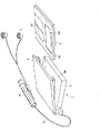
この再生装置1は、図1に示すように、光ディスク2aをカートリッジ本体2bに回転可能に収納したディスクカートリッジ2を記録媒体に用いるものであり、ディスクカートリッジ2の大きさとほぼ同じ大きさにまで小型化された携帯型の装置である。
【0014】
この再生装置1は、図1に示すように、ディスクカートリッジ2と略同じ大きさの装置本体3と、この装置本体3に接続コード4を介して接続される遠隔操作装置5と、この遠隔操作装置5に接続されるイヤホン6とから構成されている。装置本体3には、内部にディスクカートリッジ2が装着される装着部3aが設けられ、この装着部3aを開閉する蓋体7が設けられている。装着部3aには、スピンドルモータの駆動軸にディスクテーブルが取り付けられてなり、ディスクカートリッジ2の光ディスク2aをディスクテーブルに装着された状態で回転するディスク回転駆動機構や光ディスク2aの内外周に光ビームを照射し、光ディスク2aに記録された楽音信号等の情報信号の読み出しを行う光ピックアップ等が設けられている。
【0015】
ディスクカートリッジ2は、蓋体7が装着部3aを開放した状態で、光ディスク2aの一部をカートリッジ本体2bより外方に臨ませる開口部を閉塞するシャッタ部材2cの移動方向と平行な方向から装置本体3内に挿入される。そして、蓋体7が閉塞されると、光ディスク2aが装着部3aのディスクテーブルに装着され、光ディスク2aが回転可能な状態になる。そして、光ディスク2aがディスク回転駆動機構により回転されるとともに光ピックアップが光ディスク2aの内外周に亘って移動操作されることにより、光ディスク2aに記録された情報信号が読み出される。
【0016】
この再生装置1は、図2に示すように、楽音信号等の情報信号が記録された光ディスク2aに対し、光ビームを照射し反射された戻りの光ビームを検出することで、光ディスク2aに対して情報信号の読み出しを行う光ピックアップ11と、光ピックアップ11より出力された出力信号を増幅するRFアンプ12と、RFアンプ12からのRF信号をアナログ信号に変換し再生信号を生成する再生回路13と、この再生信号を増幅するアンプ14と、アンプ14で増幅された再生信号を出力するイヤホン、ヘッドホン、スピーカ等の出力器15とを備える。また、光ディスク再生装置1は、RFアンプ12の出力に基づきサーボ制御を行うサーボ回路16と、サーボ回路16からのサーボ信号に基づいて光ピックアップ11を駆動制御するドライブ回路17と、再生回路13やサーボ回路16を制御する制御回路18とを備える。
【0017】
光ピックアップ11は、装置本体3の装着部3aに設けられており、光ビームを出射する半導体レーザと、この半導体レーザより出射された光ビームを集束する対物レンズと、光ディスク2aで反射された戻りの光ビームを検出する光検出器等を備える。半導体レーザより出射された光ビームは、対物レンズにより集束され、光ディスク2aの信号記録面に照射される。そして、光ディスク2aの信号記録面で反射された戻りの光ビームは、光検出器により電気信号に変換され、光検出器は、この電気信号をRFアンプ12に供給する。また、対物レンズは、2軸アクチュエータ等の対物レンズ駆動機構に保持され、対物レンズの光軸と平行なフォーカシング方向及び対物レンズの光軸に直交するトラッキング方向に駆動変位される。
【0018】
RFアンプ12は、光ピックアップを構成する光検出器からの出力信号に基づいて、RF信号、フォーカシングエラー信号及びトラッキングエラー信号を生成する。例えばフォーカシングエラー信号は、非点収差法により生成され、トラッキングエラー信号は、3ビーム法やプッシュプル法により生成される。そして、RFアンプ12は、RF信号を再生回路13に供給し、フォーカシングエラー信号及びトラッキングエラー信号をサーボ回路16に供給する。
【0019】
再生回路13は、RFアンプ12から出力されたRF信号を2値化する2値化回路13aと、2値化回路13aで2値化されたデータを復調する復調回路13bと、復調されたデータの符号誤りを検出訂正する誤り検出訂正回路13cと、誤り訂正されたデータを伸長する伸長回路13dと、伸長されたディジタル信号をアナログ信号に変換するディジタル/アナログ変換回路(A/D変換回路)13eとを有する。再生回路13は、RFアンプ12からのRF信号を2値化、復調した後、誤り訂正を行い、誤り訂正がなされたデータを伸長し、アナログ信号に変換することにより再生信号を生成する。そして、この再生信号は、アンプ14で増幅された後、出力器15より出力される。
【0020】
RFアンプ12からフォーカシングエラー信号及びトラッキングエラー信号が供給されるサーボ回路16は、光ディスク2aを再生する際のサーボ信号を生成する。具体的に、サーボ回路16は、フォーカシングエラー信号に基づき、このフォーカシングエラー信号が0となるように、フォーカシングサーボ信号を生成し、また、トラッキングエラー信号に基づき、このトラッキングエラー信号が0となるように、トラッキングサーボ信号を生成する。そして、サーボ回路16は、フォーカシングサーボ信号及びトラッキングサーボ信号をドライブ回路17に供給する。
【0021】
ドライブ回路17は、サーボ回路16で生成されたフォーカシングサーボ信号及びトラッキングサーボ信号に基づいて、光ピックアップ11を構成する対物レンズを駆動する2軸アクチュエータを駆動制御する。ドライブ回路17は、フォーカシングサーボ信号に基づき2軸アクチュエータを駆動し、対物レンズを対物レンズの光軸と平行なフォーカシング方向に駆動変位させる。また、ドライブ回路17は、トラッキングサーボ信号に基づき2軸アクチュエータを駆動し、対物レンズの光軸に直交するトラッキング方向に対物レンズを駆動変位させる。
【0022】
制御回路18は、装置本体3に設けられた操作部からの操作信号や装置本体3に接続コード4を介して接続された遠隔操作装置5からの操作信号に基づいて上述したサーボ回路16や再生回路13等の制御を行う。
【0023】
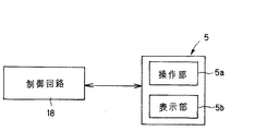
以上のような再生装置1の遠隔制御を行う遠隔操作装置5は、図3に示すように、利用者によって操作される操作部5aと装置本体3の動作状態等を表示する状態表示部5bとを有する。
【0024】
ここで、操作部5aについて詳細に説明すると、図4に示すように、操作部5aは、プッシュ型のスイッチSW1〜スイッチSW10を有する。具体的に、スイッチSW1は、装置本体3に再生動作を開始させるとともに再生中に逆方向にトラックジャンプさせるためのものであり、スイッチSW2は、再生中のデータの音質を切り換えるためのものであり、スイッチSW3は、再生動作を開始させるとともに再生中に順方向にトラックジャンプさせるためのものであり、スイッチSW4は、再生動作を一時停止させるためのものであり、スイッチSW5は、再生動作を停止させるためのものであり、スイッチSW6は、再生中の音量を小さくするためのものであり、スイッチSW7は、再生中の音量を大きくするためのものであり、スイッチSW8は、入力決定をするためのものであり、スイッチSW9は、トラック番号順に再生する通常の再生モード、ランダムに再生する再生モード等を切り換えるものであり、スイッチSW10は、表示部5bの表示形態を切り換えるためのものである。
【0025】
また、入力端子VinとスイッチSW1との間には、抵抗R0とコンデンサCが並列に接続され、スイッチSW1とスイッチSW2の間には、抵抗R1が接続され、スイッチSW2とスイッチSW3の間には、抵抗R2が接続され、スイッチSW3とスイッチSW4との間には、抵抗R3が接続され、スイッチSW4とスイッチSW5との間には、抵抗R4が接続され、スイッチSW5とスイッチSW6との間には、抵抗R5が接続され、スイッチSW6とスイッチSW7との間には、抵抗R6が接続され、スイッチSW7とスイッチSW8との間には、抵抗R7が接続され、スイッチSW8とスイッチSW9との間には、抵抗R8が接続され、スイッチSW9とスイッチSW10との間には、抵抗R9が接続されている。
【0026】
更に、出力端子Voutには、操作部5aの操作を無効化するためのスイッチSW11が設けられている。このスイッチSW11は、スライド型のスイッチであり、中央の出力端子Voutに接続された第1の端子T1を共通端子とし、端子T1の両側に設けられた第2の端子T2と第3の端子T3に選択的に接続される。第2の端子T2は、上述したスイッチSW1〜スイッチSW10に接続された端子であり、第3の端子T3は、上述したスイッチSW1〜スイッチSW10に接続されていない。したがって、スイッチSW11は、第1及び第2の端子T1、T2に接続されているときのみ、操作信号を出力端子Voutより出力可能な状態にする。
【0027】
制御回路18は、スイッチSW11が第1の端子T1と第2の端子T2を接続しているときに、スイッチSW1〜スイッチSW10の何れかが押され、導通したとき、抵抗が異なることによって出力電圧が異なり、この出力電圧を検出することで、遠隔操作装置5からの操作信号を識別し、操作信号に応じて再生回路13等を制御する。
【0028】
また、表示部5bは、再生装置1の動作状態を表示する動作表示部であり、液晶表示パネルにより形成されている。この表示部5bは、接続コード4を介して制御回路18によって制御され、制御回路18は、操作部5aからの操作信号に基づいて表示部5bの表示制御を行う。この表示部5bは、例えば光ディスク2aのTOC<table of contents>領域に記録された文字情報や、再生装置1の電源となる電池の残量表示や、再生中のデータの記録トラック番号や、現在の時刻や、音量のレベルや、光ディスク2aの残り曲数や残り時間等を表示する。
【0029】
次に、この遠隔操作装置5の構成を説明すると、図5乃至図7に示すように、本体部を構成するケース本体21と、このケース本体21の一端側に設けられる第1の操作部を構成する回動操作体22とを有する。この遠隔操作装置5は、全体が略円柱状に形成されることによって、物に引っかかりにくくし、外周面に設けられた操作釦等が不意に押されてしまって再生装置1が誤動作してしまうことを防止している。
【0030】
ケース本体21には、液晶表示パネルよりなる状態表示部23が設けられ、また、図6に示すように、長手方向に沿って一列に、再生動作を一時停止するための一時停止釦24と、再生中のデータの音質を切り換えるための音質切換釦25と、入力決定をするための入力決定釦26と、トラック番号順に再生する通常の再生モード、ランダムに再生する再生モード等を切り換える再生モード切換釦27と、状態表示部23の表示形態を切り換える表示切換釦28とが設けられている。
【0031】
また、回動操作体22は、図5及び図7に示すように、ケース本体21の長手方向に沿った図5及び図7中矢印A方向及び反矢印A方向に直線移動可能に設けられている。そして、回動操作体22は、図5に示すように、ケース本体21側の第1の位置にあるとき、図5中矢印B方向及び反矢印B方向に回動可能に設けられている。具体的に、再生装置1が動作していないときに、何れか一方に回動されると、再生装置1は、再生動作を開始し、また、再生動作中にあっては、図5中矢印B方向に回動されることで、順方向にトラックジャンプし、図5中反矢印B方向に回動されることで、逆方向にトラックジャンプする。
【0032】
また、回動操作体22は、図7に示すように、ケース本体21より引き出された第2の位置にあるときも、図7中矢印B方向及び反矢印B方向に回動する。具体的に、再生装置1は、図7中矢印B方向に回動されたとき、音量を大きくし、図7中反矢印B方向に回動されたとき、音量を小さくする。
【0033】
更に、回動操作体22には、図6及び図7に示すように、再生装置1の再生動作を停止する第2の操作部を構成する停止釦29が設けられている。遠隔操作装置5は、回動操作体22に停止釦29を設け、トラックジャンプ操作や音量調節操作を行う操作位置と再生停止操作を行う操作位置を近接させることで、使い勝手を良くしている。
【0034】
略円柱状のケース本体21は、図8に示すように、断面略円弧状の上ケース33と下ケース34とから構成されており、これら上下ケース33,34は、様々な物に当たることが多いことから機械的な強度を有するABS樹脂等により形成されている。上ケース33には、図5、図7及び図8に示すように、ケース本体21内に配設される液晶表示パネルに表示された文字等を透視して見ることができるように、略矩形の透視窓35が設けられている。この透視窓35も、表面に傷が付き液晶表示パネルの文字が見にくくなることを防止するために、剛性を有するABS樹脂で形成されている。また、上ケース33の一端部には、図8に示すように、下ケース34の一端部に設けられた筒状部に係合される略円弧状の係合凹部36が形成されている。更に、下ケース34の他端部には、再生装置1と接続するための接続コード4を外部に導出するための第1のコード導出用切欠部37が形成されている。更に、上ケース33の開口端の長手方向には、下ケース34と結合する際、下ケース34との結合位置の位置決めを行うための位置決め突起38aと下ケース34を係止するための係止突起38bが複数形成されている。
【0035】
下ケース34には、図8に示すように、内面側に、液晶表示パネル39を支持するための複数の支持部41と、液晶表示パネル39を支持するとともに位置決めを行う支持ピン42が設けられている。
【0036】
ここで、液晶表示パネル39は、図8及び図9に示すように、略同じ大きさの剛性を有するプリント配線基板43に取り付けられている。プリント配線基板43には、液晶表示パネル39の取付面と対向する面に、図4に示すプッシュ型のスイッチが設けられており、具体的には、再生動作を一時停止させるためのスイッチSW4と再生中のデータの音質を切り換えるためのスイッチSW2と入力決定をするためのスイッチSW8と再生モードの切換を行うためのスイッチSW9と表示部5bの表示形態を切り換えるためのスイッチSW10が設けられている。また、プリント配線基板43には、スイッチSW1〜スイッチSW10を無効化するためのスライド型のスイッチSW11が設けられている。更に、プリント配線基板43には、短辺方向の側縁部に、再生動作を停止させるためのスイッチSW5が設けられている。
【0037】
更に、プリント配線基板43には、下ケース34に設けられた支持ピン42が係合される位置決め孔46が形成されている。そして、このプリント配線基板43には、接続コード4が接続されている。
【0038】
そして、液晶表示パネル39が取り付けられたプリント配線基板43は、図8に示すように、液晶表示パネル39を上ケース33側にし、側縁部を支持部41に支持させ、支持ピン42を位置決め孔46に係合させることによって、位置決めされた状態で下ケース34に取り付けられる。
【0039】
また、図6及び図8に示すように、下ケース34には、イヤホンジャックを取り付けるためのジャック取付部47が一体的に形成されている。このジャック取付部47は、下ケース34の他端側から回動操作体22が取り付けられる一端側に向かって突出して設けられている。このジャック取付部47には、図8に示すように、ジャック支持部材48を介してジャック部材49がイヤホン6との接続孔49aをジャック取付部47の下ケース34の一端側の端面より外部に臨ませるようにして取り付けられる。
【0040】
このジャック取付部47には、図6に示すように、遠隔操作装置5を利用者の服や鞄等に係止させるためのクリップ部材51が設けられている。クリップ部材51は、ジャック取付部47の基端側に回動可能に取り付けられ、図示しない付勢部材によって、下ケース34側に付勢されている。
【0041】
更に、下ケース34には、図6、図8及び図10に示すように、プリント配線基板43に設けられたプッシュ型のスイッチSW4とスイッチSW2とスイッチSW8とスイッチSW9とスイッチSW10を押圧するための押圧操作部材54a〜54eを外部に臨ませるための開口部52a,52b,52c,52d,52eが設けられている。これら開口部52a〜52eの近傍には、押圧操作部材54a〜54eを回動支持する支持溝53が形成されている。
【0042】
これら開口部52a〜52eには、一体的に形成された押圧操作部材54a,54b,54c,54eが配設される。各押圧支持部材54a〜54eは、利用者によって押圧操作される操作部55と、上記支持溝53に係合される支軸56を有する回動支持部56と、スイッチSW4とスイッチSW2とスイッチSW8とスイッチSW9とスイッチSW10を押圧する押圧片57とを有し、これら押圧操作部材54a〜54eは、連結片58によって連結されている。そして、押圧片57は、下ケース34に配設されたプリント配線基板43のスイッチSW4とスイッチSW2とスイッチSW8とスイッチSW9とスイッチSW10を押圧することができるように、操作部55に対して略直交して設けられている。
【0043】
これら押圧操作部材54a〜54eは、支軸56aを支持溝53に係合させて、操作部55を開口部52a〜52eより外部に臨ませるようにして取り付けられる。そして、押圧操作部材54a〜54eは、支持溝53に係合された支軸56aを回動支点として、図10中矢印C方向に回動操作される。これによって、押圧片57は、下ケース34に配設されたプリント配線基板43のスイッチSW4とスイッチSW2とスイッチSW8とスイッチSW9とスイッチSW10を押圧する。
【0044】
なお、開口部52a〜52eの外面側には、各スイッチSW4とスイッチSW2とスイッチSW8とスイッチSW9とスイッチSW10の機能を示す機能表示部59a,59b,59c,59eが設けられている。具体的に、図6に示すように、機能表示部59aには、一時停止の表示がなされ、機能表示部59bには、サウンドの表示がなされ、機能表示部59cには、入力の表示がなされ、機能表示部59dには、再生モードの表示がなされ、機能表示部59eには、ディスプレイの表示がなされている。
【0045】
また、下ケース34には、図8及び図11に示すように、スイッチSW1〜スイッチSW10の操作を無効化するスイッチSW11をスライド操作するためのスライド操作部材61が設けられている。このスライド操作部材61は、利用者によってスライド操作される操作部62と、スライドをガイドするスライドガイド部63と、プリント配線基板43に設けられた操作子64aに係合される係合凹部64とを有する。そして、このスライド操作部材61は、下ケース34に設けられたスライドガイド孔65より操作部62を外部に臨ませ、スライドガイド部63をスライドガイド孔65に係合させ、係合凹部64をスイッチSW11の操作子64aに係合させて取り付けられる。このようなスライド操作部材61は、一方にスライド操作されたとき、図4に示すように、第1及び第2の端子T1,T2に接続され、スイッチSW1〜スイッチSW10の機能を有効化し、他方にスライドされ操作されたとき、第1及び第3の端子T1,T3に接続され、スイッチSW1〜スイッチSW10の機能を無効化する。
【0046】
また、更に、下ケース34の他端部には、図8に示すように、第1のコード導出用切欠部37とともに接続コード4を外部に導出するための第2のコード導出用切欠部66が形成されている。第1の第1のコード導出用切欠部37と第2のコード導出用切欠部66とは、上ケース33と下ケース34とが結合されたとき、接続コード4を導出しながら保持するコード保持部を構成する。また、下ケース34の開口端の長手方向には、上ケース33と結合する際、上ケース33側の位置決め突起38aと係合し、位置決めを行う位置決め突部67aと、上ケース33側の係止突起38bが係合する係止孔67bが複数形成されている。上ケース33と下ケース34とは、上ケース38aの位置決め突起38aと下ケース34側の位置決め突部67aとを係合させ、上ケース33側の係止突起38bを下ケース34側の係止孔67bに係止させることで結合される。
【0047】
ところで、下ケース34の一端部には、図8に示すように、第1の操作部を構成する回動操作体22を取り付けるための筒状部71が設けられている。この筒状部71は、図12及び図13に示すように、回動操作体22が取り付けられたときに、利用者の使用感を良くするため、ケース本体21の外周面と回動操作体22の外周面とが略面一となるようにするため、境界部に段差部72を設け、ケース本体21より縮径して形成されている。この筒状部71は、回動操作体22の回動をガイドする略半円弧状の第1の回動ガイド片73と第2の回動ガイド片74とから構成され、相対向する位置に、回動規制凹部75,76が形成されている。
【0048】
第1の回動ガイド片73と第2の回動ガイド片74には、略中央部に第2の操作部を構成する押し釦を支持する支持部材を係止するための係止孔77,78が形成されている。更に、筒状部71の基端側であって、第1の回動ガイド片73と第2の回動ガイド片74とを連結する連結部79,80の内面側には、回動操作体22を基準位置に回動付勢する付勢部材が係止される係止溝81,82が形成されている。
【0049】
また、第1の回動ガイド片73の基端部、すなわち、回動操作体22がケース本体21より引き出されたとき外部に臨む位置には、回動操作体22をケース本体21より引き出された第2の位置で回動操作する際の機能を示す機能表示部83が形成されている。具体的に、機能表示部83には、回動操作体22の第2の位置での回動操作は音量調節であることから、音量を大きくする方に+表示がなされ、音量を小さくする方に−表示がなされている。
【0050】
以上のような筒状部71の外側に取り付けられる回動操作体22は、図12に示すように、外径がケース本体21の外径と略同じとなし、内径が筒状部71の外径と略同じとなす略リング状に形成されている。すなわち、回動操作体22は、外周面が筒状部71に取り付けられた際にケース本体21の外周面と略面一をなし、利用者の手触りが良くなるように形成されている。
【0051】
回動操作体22の表面には、回動操作体22がケース本体21側の第1の位置で回動操作する際の機能を示す機能表示部84が形成されている。機能表示部84は、回動操作体22の第2の位置での回動操作がトラックジャンプであることから、ジャンプ方向を示す矢印で構成されている。また、この機能表示部84の近傍には、回動操作体22を第2の位置に引き出したとき、音量調節を行うことができることを利用者に示唆するための表示部85も設けられている。
【0052】
このリング状の回動操作体22には、厚さ方向の中程に、略矩形状の仕切壁86が設けられ、この仕切壁86は、回動操作体22の内周面に回動規制片87,88を介して設けられている。回動操作体22は、筒状部71に挿入されたとき、回動規制片87,88が筒状部71側の回動規制凹部75,76に係合される。これによって、筒状部71に挿入された回動操作体22は、回動規制片87,88が回動規制凹部75,76の側縁に突き当たるまで回動可能となり、回動範囲が規制される。また、この回動操作体22は、第1及び第2の回動ガイド片73,74にガイドされて、第1及び第2の回動ガイド片73,74の基端側の第1の位置と先端側の第2の位置とに亘って直線移動される。
【0053】
このように回動操作体22が挿入された筒状部71には、図12に示すように、先端側に第2の操作部である停止釦29を構成する押し釦91と、この押し釦91を支持する支持部材92が配設される。押し釦91は、略円形の押圧操作部93と、押圧操作部93の基端側に設けられたフランジ部94とから構成されている。この押し釦91は、停止釦29として機能するものであるから、停止動作を機能表示する機能表示部95が設けられている。また、押し釦91の裏面側略中央には、図9に示すプリント配線基板43の短辺方向の側縁に設けられたプッシュ型のスイッチSW5を押圧するための押圧シャフト101を取り付けるための取付孔96が形成されている。
【0054】
また、支持部材92は、押し釦91を外部に臨ませる開口部97と、この開口部97の周縁部であって、押し釦91のフランジ部94が係止される係止部98と、筒状部71に取り付けるための係止片99,100とを有する。押し釦91は、押圧操作部93を開口部97より外部に臨ませ、フランジ部94を係止部98に係止させるようにして、支持部材92に配設される。また、取付孔96には、押圧シャフト101が取り付けられる。そして、押し釦91が配設された支持部材92は、回動操作体22が配設された筒状部71に配設された状態で、係止片99,100を係止孔77,78に係止させることにより取り付けられる。
【0055】
このように取り付けられた押し釦91は、図17に示すように、回動操作体22が第1及び第2の回動ガイド片73,74の基端側の第1の位置にあるとき突出し、先端側の第2の位置にあるとき、回動操作体22の端部と略面一をなす。そして、押し釦91の取付孔96に取り付けられた押圧シャフト101は、押し釦91が押圧操作されたとき、プリント配線基板43の短辺方向の側縁部に設けられたスイッチSW5を押圧する。また、押し釦91は、回動操作体22が第2の位置にあるとき、回動操作体22の開口端と略面一をなし、操作しづらくなることから、利用者が音量を調節しているときに、誤って停止釦29である押し釦91を押してしまい、再生装置1の再生動作が停止してしまうことを防止している。更に、押し釦91により構成される停止釦29は、操作位置が回動操作体22に設けられることで、回動操作体22の回動操作位置と近いことから、使い勝手を良くすることができる。
【0056】
また、下ケース34の筒状部71に挿入された回動操作体22は、図13及び図14に示すように、取付部材103によって筒状部71に取り付けられる。この取付部材103は、筒状部71の基端側から挿入されるものであり、略円筒状の基体部104を有する。この基体部104は、内部に、回動操作体22を基準位置に回動付勢する付勢部材である捻りコイルバネ110が配設され、両端部110a,110bがそれぞれ開口部110c,110dより外部に臨まされている。これら捻りコイルバネ110の端部110a,110bは、下ケース34の筒状部71の内面に設けられた係止溝81,82にそれぞれ係止される。これによって、回動操作体22は、基準位置に保持される。
【0057】
基体部104の筒状部71への挿入側の一端には、回動操作体22を筒状部71に取り付けるための一対の取付片105,106が形成されている。取付片105,106は、先端部に係止部105a,106aが設けられ、これら係止片105a,106aは、筒状部71に取り付けられた回動操作体22の仕切壁86に係止される。これによって、取付部材103は、回動操作体22と一体的に直線移動される。また、回動操作体22の略中央部には、押圧シャフト101が挿通される挿通孔107が形成されている。
【0058】
基体部104の他端側には、端子部材109を取り付けるための端子取付部108が形成されている。端子取付部108に取り付けられる端子部材109は、図13及び図14に示すように、導電性の金属板を打ち抜き折曲することによって、第1乃至第4の弾性接点アーム111,112,113,114が設けられている。第1及び第2の弾性接点アーム111,112は、端子取付部108の一方の側に設けられ、装置本体3に再生動作を開始させるとともに再生中に順方向にトラックジャンプさせるためのスイッチSW3と再生中の音量を大きくするためのスイッチSW7を構成し、第3及び第4の弾性接点アーム113,114は、端子取付部108の他方の側に設けられ、装置本体3に再生動作を開始させるとともに再生中に逆方向にトラックジャンプさせるためのスイッチSW1と再生中の音量を小さくするためのスイッチSW6を構成する。
【0059】
図15(A)及び図15(B)に示すように、第1乃至第4の弾性接点アーム111〜114は、プリント配線基板43に設けられた第1乃至第6の接点部115,116,117,118,119,120に選択的に弾接される。第1乃至第3の接点部115〜117は、一方の側に一列に並んで設けられ、回動操作体22が一方向に回動されたときに第1及び第2の弾性接点アーム111,112が弾接される。そして、第2の接点部116は、コモン端子であり、第1及び第2の弾性接点アーム111,112は、第1及び第2の接点部115,116と第2及び第3の接点部116,117とに選択的に弾接される。
【0060】
すなわち、図15(A)に示すように、回動操作体22がケース本体21側の第1の位置で一方向に回動されるとき、第1及び第2の弾性接点アーム111,112は、第1及び第2の接点部115,116に弾接し、図4に示す再生動作を開始させるとともに再生中に順方向にトラックジャンプさせるためのスイッチSW3として機能する。また、図15(B)に示すように、回動操作体22がケース本体21から引き出された第2の位置で一方向に回動されるとき、第1及び第2の弾性接点アーム111,112は、第2及び第3の接点部116,117に弾接し、再生中の音量を大きくするためのスイッチSW7として機能する。
【0061】
また、第4乃至第6の接点部118〜120は、他方の側に一列に並んで設けられており、回動操作体22が他方向に回動されたときに第3及び第4の弾性接点アーム113,114が弾接される。そして、第5の接点部119は、コモン端子であり、第3及び第4の弾性接点アーム113,114は、第4及び第5の接点部117,118と第5及び第6の接点部119,120とに選択的に弾接される。
【0062】
すなわち、図15(A)に示すように、回動操作体22がケース本体21側の第1の位置で他方向に回動されるとき、第2及び第3の弾性接点アーム113,114は、第4及び第5の接点部118,119に弾接し、図4に示す装置本体3に再生動作を開始させるとともに再生中に逆方向にトラックジャンプさせるためのスイッチSW1として機能する。また、図15(B)に示すように、回動操作体22がケース本体21から引き出された第2の位置で他方向に回動されるとき、第2及び第3の弾性接点アーム113,114は、第5及び第6の接点部119,120に弾接し、再生中の音量を小さくするためのスイッチSW6として機能する。
【0063】
更に、図16に示すように、取付部材103の基体部104には、他端側に、回動操作体22を第1の位置と第2の位置に亘って直線移動操作する際に、利用者にクリック感を与えるためのクリック感付与板123が設けられている。このクリック感付与板123は、回動操作体22の直線移動方向と略直交する図16中矢印D方向に変位可能に設けられている。このクリック感付与板123は、略円弧状の第1の係合凹部124と第2の係合凹部125とが連続して設けられ、これら係合凹部124,125の境界部に突出部126が形成されている。
【0064】
一方、プリント配線基板43の短辺方向の一端部には、フレーム127が設けられ、このフレーム127の略中央部には、クリック感付与板123の第1及び第2の係合凹部124,125に係脱する係合部材となる球状体128が取り付けられている。クリック感付与板123は、取付部材103が回動操作体22が直線移動するとき、プリント配線基板43側の球状体128が突出部126を乗り上げることで弾性変位し、第1の係合凹部124と第2の係合凹部125の何れかに球状体128が係合し弾性復帰することで、クリック感を発生する。また、回動操作体22は、球状体128が第1の係合凹部124と第2の係合凹部125の何れかに係合されることによって、第1の位置と第2の位置の何れかに保持される。具体的に、球状体128は、筒状部71側の第1の係合凹部124に係合することによって、回動操作体22を第1の位置に保持し、第2の係合凹部125に係合することによって、回動操作体22を第2の位置に保持する。
【0065】
なお、図14に示すように、クリック感付与板123の変位量の小さい基端部には、取付部材103に取り付けられた回動操作体22が下ケース34の筒状部71より抜け落ちることを防止するストッパ129が設けられている。このストッパ129は、下ケース43の筒状部71の基端部に係止されることで、回動操作体22の第2の位置への移動を規制するとともに、取付部材103に取り付けられた回動操作体22が筒状部71より抜け落ちることを防止する。
【0066】
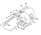
以上のように構成された遠隔操作装置5では、先ず、下ケース34に、図8及び図10に示すように、押圧支持部材54a〜54eを、支軸56aを支持溝53に係合させ、操作部55を開口部52a〜52eより外部に臨ませるようにして取り付け、次いで、液晶表示パネル39が取り付けられたプリント配線基板43を液晶表示パネル39を上ケース33側にして配設する。次いで、下ケース34の筒状部71には、図8及び図12に示すように、回動規制片87,88が筒状部71側の回動規制凹部75,76に係合するように回動操作体22が挿入される。そして、フランジ部94を係止部98に係止させるようにして押し釦91が配設された支持部材92は、係止片99,100を筒状部71の係止孔77,78に係止させることにより筒状部71に取り付けられる。押し釦91の取付孔96に取り付けられた押圧シャフト101は、図17に示すように、プリント配線基板43のスイッチSW5に臨まされる。
【0067】
一方、下ケース34側からは、取付部材103が挿通孔107に押圧シャフト101を挿通させて筒状部71に取り付けられる。これにより、取付部材103の取付片105,106は、筒状部71に取り付けられた回動操作体22の仕切壁86に係止され、回動操作体22と一体的に直線移動可能な状態になる。また、図16に示すように、下ケース34に配設された球状体128は、基体部104のクリック感付与板123の第1の係合凹部124又は第2の係合凹部125の何れかに係合される。
【0068】
また、図13に示すように、基体部104に配設された捻りコイルバネ110の両端部110a,110bは、筒状部71の内面に設けられた係止溝81,82にそれぞれ係止され、取付部材103に一体的に取り付けられた回動操作体22は、基準位置に保持される。すなわち、図14に示すように、第1及び第2の弾性接点アーム111,112が、第1、第2及び第3の接点部115,116,117上に位置し、第3及び第4の弾性接点アーム113,114が、第4、第5及び第6の弾性接点アーム113,114上に位置し、これらの弾性接点アーム111〜114が何れの接点部115〜120にも接触していない状態となる。
【0069】
この後、下ケース34は、位置決め突部67aが上ケース33側の位置決め突起38aと係合し、係止孔67bに上ケース33側の係止突起38bが係合し、更に止めねじ等により結合される。このように回動操作体22がケース本体21に取り付けられると、図17に示すように、回動操作体22は、筒状部71を構成する第1及び第2の回動ガイド片73,74に沿って、ケース本体21側の第1の位置とケース本体21から離間した第2の位置に直線移動する。回動操作体22は、第2の位置にあるとき、押し釦91と略面一をなすことから、押し釦91の操作がし辛くなり、利用者が音量を調節しているときに、誤って停止釦29である押し釦91を押してしまい、再生装置1の再生動作が停止してしまうことを防止している。
【0070】
また、回動操作体22が第1の位置や第2の位置にあるとき、回動操作体22は、筒状部71の周回り方向に、捻りコイルバネ110の付勢力に抗して回動される。これによって、回動操作体22と一体的に回動する取付部材103に設けられた第1及び第2の弾性接点アーム111,112は、プリント配線基板43の第1及び第2の接点部115,116と第2及び第3の接点部116,117に択一的に弾接され、また、第3及び第4の弾性接点アーム113,114は、第4及び第5の接点部118,119と第5及び第6の接点部119,120に択一的に弾接される。このように、遠隔操作装置5では、第1の位置と第2の位置に移動可能な回動操作体22を用いることで、従来のように、不意にスイッチが押されてしまい、機器が利用者の意に反して動作することを防止することができる。
【0071】
次に、再生装置1に接続されている遠隔操作装置5の操作方法について説明する。先ず、図1及び図2に示すように、再生装置1の装着部3aに装着されたディスクカートリッジ2の光ディスク2aの再生を行うときの遠隔操作装置5の操作を説明する。光ディスク2aの再生を行うときには、図5に示すように、ケース本体21側の第1の位置にある回動操作体22を、取付部材103の捻りコイルバネ110の付勢力に抗して図5中矢印B又は反矢印B方向に回動操作する。すると、回動操作体22と一体的に回動する取付部材103に設けられた第1及び第2の弾性接点アーム111,112は、プリント配線基板43の第1及び第2の接点部115,116若しくは第4若しくは第5の接点部118,119に弾接される。これによって、図4に示すスイッチSW1若しくはスイッチSW3はオンとなり、再生動作の開始を示す信号は、接続コード4を介して制御回路18に出力される。制御回路18は、この信号に基づいて、ディスク回転駆動機構のスピンドルモータと光ピックアップ11を駆動する。
【0072】
すると、光ピックアップ11は、図2に示すように、半導体レーザより光ビームを出射し、光ディスク2aの信号記録面に光ビームを照射し、光ディスク2aの信号記録面で反射した戻りの光ビームを光検出器で検出することで、情報信号の読み出しを行う。そして、光ピックアップ11の光検出器は、照射された光ビームを電気信号に変換し、この電気信号をRFアンプ12に供給する。すると、RFアンプ12は、光検出器からの出力信号に基づいて、RF信号、フォーカスエラー信号及びトラッキングエラー信号を生成し、RF信号を再生回路13に供給し、フォーカスエラー信号及びトラッキングエラー信号をサーボ回路16に供給する。再生回路13は、RFアンプ12からのRF信号を2値化、復調した後、誤り訂正を行い、誤り訂正がなされたデータを伸長し、アナログ信号に変換することにより再生信号を生成する。そして、アンプ14で増幅された再生信号は、アンプ14で増幅され、イヤホン、ヘッドホン、スピーカ等の出力器15より出力される。
【0073】
このように再生装置1が再生動作を行っているときに、遠隔操作装置5は、回動操作体22を用いることにより、順方向と逆方向のトラックジャンプと、音量調節を行うことができる。
【0074】
先ず、順方向のトラックジャンプ操作するときには、図16に示す球状体128が第1の係合凹部124に係合することで第1の位置に保持された回動操作体22を取付部材103の捻りコイルバネ110の付勢力に抗して図5中矢印B方向に回動操作する。すると、回動操作体22と一体的に回動する取付部材103に設けられた第1及び第2の弾性接点アーム111,112は、プリント配線基板43の第1及び第2の接点部115,116に弾接される。これによって、図4に示すスイッチSW3は、オンの状態となり、順方向のトラックジャンプ、すなわち再生中のデータの次の記録トラックの先頭から再生するための信号を制御回路18に出力する。これに基づいて、制御回路18は、光ピックアップ11を光ディスク2aの内外周に亘って移動させ、次のトラックの先頭の読み出し処理を開始する。
【0075】
また、逆方向のトラックジャンプ操作するときには、第1の位置にある回動操作体22を取付部材103の捻りコイルバネ110の付勢力に抗して図5中反矢印B方向に回動操作する。すると、回動操作体22と一体的に回動する取付部材103に設けられた第3及び第4の弾性接点アーム113,114は、プリント配線基板43の第4及び第5の接点部118,119に弾接される。これによって、図4に示すスイッチSW1は、オンの状態となり、逆方向のトラックジャンプ、すなわち再生中のデータの頭出しをするための信号を制御回路18に出力する。これに基づいて、制御回路18は、光ピックアップ11を光ディスク2aの内外周に亘って移動させ、再生中の記録トラックの先頭からデータの読出処理を開始する。
【0076】
以上のように、遠隔操作装置5では、順方向や逆方向にトラックジャンプ操作を行うとき、回動操作体22に、トラックジャンプ方向を示す機能表示部84が設けられていることから、簡単に回動方向を認識することができる。
【0077】
更に、再生中のデータの音量を大きくするときには、回動操作体22が図5中矢印A方向に引き出し操作され第2の位置に直線移動され、図7に示す状態となる。このとき、回動操作体22には、表示部85が設けられていることから、利用者は、回動操作体22の引き出し方向を容易に認識することができる。また、このとき、図16に示す球状体128は、突出部126を乗り上げが第2の係合凹部125に係合し、このとき、クリック感付与板123が弾性変位する。これによって、利用者は、クリック感が付与され、回動操作体22が第2の位置に直線移動したことを認識することができる。
【0078】
そして、回動操作体22がケース本体21から離間した第2の位置にあるとき、回動操作体22は、取付部材103の捻りコイルバネ110の付勢力に抗して図7中矢印B方向に回動される。すると、回動操作体22と一体的に回動する取付部材103に設けられた第1及び第2の弾性接点アーム111,112は、プリント配線基板43の第2及び第3の接点部116,117に弾接される。これによって、図4に示すスイッチSW7は、オンの状態となり、音量を大きくする信号を制御回路18に出力する。これに基づいて、制御回路18は、音量を1段階レベルを上げて出力器15より出力される音量を大きくする。
【0079】
また、再生中のデータの音量を小さくするときには、第2の位置にある回動操作体22を取付部材103の捻りコイルバネ110の付勢力に抗して図7中反矢印B方向に回動操作する。すると、回動操作体22と一体的に回動する取付部材103に設けられた第3及び第4の弾性接点アーム113,114は、プリント配線基板43の第5及び第6の接点部119,120に弾接される。これによって、図4に示すスイッチSW6は、オンの状態となり、音量を小さくする信号を制御回路18に出力する。これに基づいて、制御回路18は、音量を1段階レベルを下げて出力器15より出力される音量を小さくする。
【0080】
以上のように、遠隔操作装置5では、音量調整を行うとき、回動操作体22が第2の位置に移動されたときに外部に臨む筒状部71に機能表示部83が設けられていることから、簡単に回動方向を認識することができる。
【0081】
更に、再生装置1の再生動作を停止するときには、回動操作体22が第1の位置と第2の位置にあるかを問わず、停止釦29が押される。すると、図17に示すように、プリント配線基板43の短辺方向の側縁部に設けられたスイッチSW5が押圧シャフト101により押圧され、オンの状態となり、このスイッチSW5は、再生動作の停止を示す信号を制御回路18に出力する。これに基づいて、制御回路18は、ディスク回転駆動機構や光ピックアップ11等の動作を停止する。
【0082】
ところで、音量調節は、通常利用者が音を聞きながら行うものである。この遠隔操作装置5では、図17に示すように、回動操作体22が音量調節を行う第2の位置にあるとき、停止釦29が回動操作体22の開口端と略面一となし、操作しずらい状態とすることで、利用者が音量を調節しているときに、誤って停止釦29である押し釦91を押してしまい、再生装置1の再生動作が停止してしまうことを防止している。
【0083】
ケース本体21を構成する下ケース34に設けられた一時停止釦24と音質切換釦25と入力決定釦26と再生モード切換釦27と表示切換釦28を操作するときには、図10に示すように、所定の操作釦の開口部52a〜52eより外部に臨まされた操作部55が押圧されると、支持溝53に係合された支軸56aを回動支点として、図10中矢印C方向に回動操作される。これによって、押圧片57は、下ケース34に配設されたプリント配線基板43のスイッチSW4,2,8,9,10を押圧する。すると、スイッチSW4,2,8,9,10は、各スイッチに対応した信号を制御回路18の出力し、これに基づいて、制御回路18は、各回路の動作を制御する。
【0084】
以上のような遠隔操作装置5は、回動操作体22を用いることによって、再生装置1の複数の機能を実行することができることから、遠隔操作装置5の小型化を図ることができるとともに、操作性の向上を図ることができる。また、遠隔操作装置5は、回動操作体22に停止釦29を設け、トラックジャンプ操作や音量調節操作を行う位置と再生停止操作を行う位置を近接させることで、使い勝手を良くしている。
【0085】
更に、遠隔操作装置5は、全体の形状を略円柱状とし、物等が引っかかりにくい形状とされているので、物等に当たって利用者の意に反してスイッチがオンとなってしまうことを防止することができる。また、再生装置1の機能の中で特に基本的な機能である記録媒体の再生機能、トラックジャンプ機能、音量調節機能の操作は、物等が当たってもスイッチがオンとならない回動操作体22によって行うことから、再生装置1の誤動作を防止することができる。更に、遠隔操作装置5では、図17に示すように、回動操作体22が音量調節を行う第2の位置にあるとき、停止釦29が回動操作体22の開口端と略面一となし、操作しずらい状態とすることで、利用者が音を聞きながら音量を調節しているときに、誤って停止釦29を押してしまい、再生装置1の再生動作が停止してしまうことを防止することができる。
【0086】
以上、ディスクカートリッジ2の再生装置1を例により説明したが、本発明は、光ディスク単体を記録媒体に用いる再生装置やテープカセットを記録媒体に用いる再生装置の遠隔操作装置に適用することもできる。
【0087】
【発明の効果】
本発明によれば、操作部が第1の位置と第2の位置のそれぞれで2方向に回動操作することができ、これによってケース本体の小型化を図ることができるとともに、操作性の向上を図ることができる。
【図面の簡単な説明】
【図1】光ディスクの再生装置に遠隔操作装置が接続された状態を示す斜視図である。
【図2】上記再生装置のブロック図である。
【図3】遠隔操作装置の構成を説明するブロック図である。
【図4】遠隔操作装置の回路図である。
【図5】遠隔操作装置を前面側から見た斜視図である。
【図6】遠隔操作装置を背面側から見た斜視図である。
【図7】遠隔操作装置の回動操作体が第2の位置にケース本体から引き出された状態を示す斜視図である。
【図8】遠隔操作装置の分解斜視図である。
【図9】液晶表示パネルが取り付けられたプリント配線基板の斜視図である。
【図10】プッシュ型の操作部の構成を説明する断面図である。
【図11】スライド型の操作部の構成を説明する斜視図である。
【図12】回動操作体のケース本体の筒状部への取付を説明するための斜視図である。
【図13】回動操作体をケース本体の筒状部に取り付けるための取付部材を説明する斜視図である。
【図14】回動操作体側に設けられる端子部材に設けられた第1乃至第4の弾性接点アームとプリント配線基板に設けられた第1乃至第6の接点部との関係を説明する斜視図である。
【図15】(A)は、回動操作体がケース本体側の第1の位置にあるときの、第1乃至第4の弾性接点アームと第1乃至第6の接点部との位置関係を説明する図であり、(B)は、回動操作体がケース本体より引き出された第2の位置にあるときの、第1乃至第4の弾性接点アームと第1乃至第6の接点部との位置関係を説明する図である。
【図16】クリック感付与板とプリント配線基板に設けられた球状体との関係を説明する斜視図である。
【図17】第2の操作部である停止釦の構成を説明する断面図である。なお、本図では、取付部材を省略する。
【符号の説明】
1 再生装置、2 ディスクカートリッジ、5 遠隔操作装置、6 イヤホン、21 ケース本体、22 回動操作体、33 上ケース、34 下ケース、43プリント配線基板、71 筒状部、73 第1の回動ガイド片、74 第2の回動ガイド片、75 第1の回動規制凹部、76 第2の回動規制凹部、87,88 回動規制片、91 押し釦、92 支持部材、101 押圧シャフト、103 取付部材、110 捻りコイルバネ、111〜114 第1乃至第4の弾性接点アーム、115〜120 第1乃至第6の接点部、123 クリック感付与板、128 球状体、129 ストッパ
[0001]
BACKGROUND OF THE INVENTION
  The present invention provides data switching operations and other operations.etcCan be performed with one operation unitOperating deviceAbout.
[0002]
[Prior art]
2. Description of the Related Art Conventionally, in a disk cartridge playback apparatus that rotatably stores an optical disk on which an information signal such as a musical sound signal is stored, a portable type that has been downsized to approximately the same size as a disk cartridge that serves as a recording medium. There is something. This portable playback device has a device main body in which a disk cartridge is mounted and a playback unit and an operation unit for playing back an optical disk are provided. Earphones are connected to the apparatus body via a connection cord. A portable playback device is usually used by storing the device main body in a bag, pulling out the earphone from the bag, and mounting the earphone on the auricle. Therefore, the playback apparatus is inconvenient to operate because the apparatus main body is housed in the bag.
[0003]
Thus, some portable playback devices include a remote control device provided in the middle of an earphone connection cord. This remote control device is a push button type playback start button, playback stop button, forward trunk jump button, reverse track jump button, volume increasing volume, so that basic operations of the playback device can be performed. A button, a volume minus button for decreasing the volume, and the like are provided.
[0004]
The playback device provided with such a remote operation device can be operated with the remote operation device without being operated with the operation unit provided in the device main body, so that the convenience is improved. .
[0005]
[Problems to be solved by the invention]
By the way, since the remote control device is provided in the middle of the connection cord of the earphone, if it becomes too large and heavy, the feeling of wearing the earphone is deteriorated. On the other hand, since the playback device is multi-functional, the number of operation buttons provided on the remote control device tends to increase. And if a remote control device has too many operation buttons, a user's usability will worsen.
[0006]
In addition, since each operation button provided on the remote control device is a push button type, it is unexpectedly pressed when hitting various objects, and the function of the playback device is executed against the intention of the user. May end up. For example, if the playback start button is pressed against the user's will, playback is performed without the user's knowledge and power is consumed. Also, if the track jump button or the playback stop button is pressed during playback, the song that the user is currently listening to suddenly changes or stops, giving the user an unpleasant feeling.
[0007]
  Therefore, the present invention can reduce the size and improve the operability by allowing a plurality of operations to be performed with one operation unit.Operating deviceThe purpose is to provide.
[0008]
  Further, the present invention can prevent the operation unit from being operated unexpectedly by hitting an object or the like.Operating deviceThe purpose is to provide.
[0009]
[Means for Solving the Problems]
  In order to solve the above-described problems, the operating device according to the present invention is movable to a first position and a second position with respect to the case body, and rotates in two directions at each position. A first operation signal is generated based on an operable first operation unit and a rotation operation when the first operation unit is in the first position, and the first operation unit is configured as described above. A circuit for generating a second operation signal based on a rotation operation when in the second position;The rotation operation is an operation for rotating the entire first operation unit.
[0012]
DETAILED DESCRIPTION OF THE INVENTION
Hereinafter, a remote control device to which the present invention is applied and a playback device using the remote control device will be described with reference to the drawings.
[0013]
As shown in FIG. 1, the reproducing apparatus 1 uses a disk cartridge 2 in which an optical disk 2a is rotatably housed in a cartridge body 2b as a recording medium, and is small in size to approximately the same size as the disk cartridge 2. It is a portable device.
[0014]
As shown in FIG. 1, the reproducing apparatus 1 includes an apparatus body 3 that is substantially the same size as the disk cartridge 2, a remote operation apparatus 5 that is connected to the apparatus body 3 via a connection cord 4, and the remote operation. The earphone 6 is connected to the device 5. The apparatus main body 3 is provided with a mounting portion 3a in which the disk cartridge 2 is mounted, and a lid 7 for opening and closing the mounting portion 3a. A disk table is attached to the drive shaft of the spindle motor in the mounting portion 3a, and the optical disk 2a of the disk cartridge 2 rotates with the optical disk 2a mounted on the disk table. , And an optical pickup for reading out information signals such as musical tone signals recorded on the optical disc 2a.
[0015]
The disc cartridge 2 is a device in a direction parallel to the moving direction of the shutter member 2c that closes an opening that allows a part of the optical disc 2a to face outward from the cartridge body 2b in a state in which the lid 7 opens the mounting portion 3a. It is inserted into the main body 3. When the lid 7 is closed, the optical disk 2a is mounted on the disk table of the mounting portion 3a, and the optical disk 2a becomes rotatable. The optical disk 2a is rotated by the disk rotation drive mechanism and the optical pickup is moved over the inner and outer circumferences of the optical disk 2a, whereby the information signal recorded on the optical disk 2a is read.
[0016]
As shown in FIG. 2, the reproducing apparatus 1 irradiates an optical disk 2a on which an information signal such as a musical sound signal is recorded and irradiates the optical beam 2a and detects a return light beam reflected thereby. An optical pickup 11 that reads out an information signal, an RF amplifier 12 that amplifies the output signal output from the optical pickup 11, and a reproduction circuit 13 that converts the RF signal from the RF amplifier 12 into an analog signal and generates a reproduction signal. And an amplifier 14 that amplifies the reproduction signal, and an output device 15 such as an earphone, a headphone, and a speaker that outputs the reproduction signal amplified by the amplifier 14. The optical disk reproducing apparatus 1 includes a servo circuit 16 that performs servo control based on the output of the RF amplifier 12, a drive circuit 17 that drives and controls the optical pickup 11 based on a servo signal from the servo circuit 16, a reproduction circuit 13, And a control circuit 18 for controlling the servo circuit 16.
[0017]
The optical pickup 11 is provided in the mounting portion 3a of the apparatus body 3, and includes a semiconductor laser that emits a light beam, an objective lens that focuses the light beam emitted from the semiconductor laser, and a return reflected by the optical disc 2a. A light detector for detecting the light beam. The light beam emitted from the semiconductor laser is focused by the objective lens and irradiated onto the signal recording surface of the optical disc 2a. The returned light beam reflected by the signal recording surface of the optical disc 2 a is converted into an electrical signal by the photodetector, and the photodetector supplies the electrical signal to the RF amplifier 12. The objective lens is held by an objective lens driving mechanism such as a biaxial actuator, and is driven and displaced in a focusing direction parallel to the optical axis of the objective lens and a tracking direction orthogonal to the optical axis of the objective lens.
[0018]
The RF amplifier 12 generates an RF signal, a focusing error signal, and a tracking error signal based on an output signal from a photodetector constituting the optical pickup. For example, the focusing error signal is generated by the astigmatism method, and the tracking error signal is generated by the three beam method or the push-pull method. The RF amplifier 12 supplies the RF signal to the reproduction circuit 13 and supplies the focusing error signal and the tracking error signal to the servo circuit 16.
[0019]
The reproduction circuit 13 includes a binarization circuit 13a for binarizing the RF signal output from the RF amplifier 12, a demodulation circuit 13b for demodulating data binarized by the binarization circuit 13a, and demodulated data. Error detection / correction circuit 13c for detecting and correcting the sign error of data, decompression circuit 13d for decompressing the error-corrected data, and digital / analog conversion circuit (A / D conversion circuit) for converting the decompressed digital signal into an analog signal 13e. The reproduction circuit 13 binarizes and demodulates the RF signal from the RF amplifier 12, performs error correction, expands the data subjected to error correction, and converts it into an analog signal to generate a reproduction signal. The reproduction signal is amplified by the amplifier 14 and then output from the output unit 15.
[0020]
A servo circuit 16 to which a focusing error signal and a tracking error signal are supplied from the RF amplifier 12 generates a servo signal for reproducing the optical disc 2a. Specifically, the servo circuit 16 generates a focusing servo signal based on the focusing error signal so that the focusing error signal becomes 0, and the tracking error signal becomes 0 based on the tracking error signal. In addition, a tracking servo signal is generated. Then, the servo circuit 16 supplies a focusing servo signal and a tracking servo signal to the drive circuit 17.
[0021]
The drive circuit 17 drives and controls the biaxial actuator that drives the objective lens that constitutes the optical pickup 11 based on the focusing servo signal and the tracking servo signal generated by the servo circuit 16. The drive circuit 17 drives the biaxial actuator based on the focusing servo signal, and drives and displaces the objective lens in the focusing direction parallel to the optical axis of the objective lens. The drive circuit 17 drives the biaxial actuator based on the tracking servo signal, and drives and displaces the objective lens in the tracking direction orthogonal to the optical axis of the objective lens.
[0022]
The control circuit 18 performs the above-described servo circuit 16 and reproduction based on an operation signal from an operation unit provided in the apparatus body 3 and an operation signal from the remote operation apparatus 5 connected to the apparatus body 3 via the connection cord 4. Control of the circuit 13 and the like is performed.
[0023]
As shown in FIG. 3, the remote operation device 5 that performs remote control of the playback device 1 as described above includes an operation unit 5 a operated by a user, a state display unit 5 b that displays an operation state of the device body 3, and the like. Have
[0024]
Here, the operation unit 5a will be described in detail. As shown in FIG. 4, the operation unit 5a includes push-type switches SW1 to SW10. Specifically, the switch SW1 is for causing the apparatus main body 3 to start a reproduction operation and for causing a track jump in the reverse direction during reproduction, and the switch SW2 is for switching the sound quality of the data being reproduced. The switch SW3 is for starting a playback operation and for causing a track jump in the forward direction during playback, the switch SW4 is for temporarily stopping the playback operation, and the switch SW5 is for stopping the playback operation. The switch SW6 is for reducing the volume during playback, the switch SW7 is for increasing the volume during playback, and the switch SW8 is for determining input. The switch SW9 is a normal playback mode for playback in the order of track numbers and a playback mode for random playback. Etc. are those for switching the switch SW10 is for switching the display mode of the display unit 5b.
[0025]
A resistor R0 and a capacitor C are connected in parallel between the input terminal Vin and the switch SW1, a resistor R1 is connected between the switch SW1 and the switch SW2, and between the switch SW2 and the switch SW3. The resistor R2 is connected, the resistor R3 is connected between the switch SW3 and the switch SW4, the resistor R4 is connected between the switch SW4 and the switch SW5, and between the switch SW5 and the switch SW6. The resistor R5 is connected, the resistor R6 is connected between the switch SW6 and the switch SW7, the resistor R7 is connected between the switch SW7 and the switch SW8, and between the switch SW8 and the switch SW9. Is connected to a resistor R8, and a resistor R9 is connected between the switch SW9 and the switch SW10.
[0026]
Furthermore, the output terminal Vout is provided with a switch SW11 for invalidating the operation of the operation unit 5a. The switch SW11 is a slide-type switch, and the first terminal T1 connected to the central output terminal Vout is a common terminal, and the second terminal T2 and the third terminal T3 provided on both sides of the terminal T1. Selectively connected. The second terminal T2 is a terminal connected to the switches SW1 to SW10 described above, and the third terminal T3 is not connected to the switches SW1 to SW10 described above. Therefore, only when the switch SW11 is connected to the first and second terminals T1 and T2, the switch SW11 enables the operation signal to be output from the output terminal Vout.
[0027]
When the switch SW11 is connected to the first terminal T1 and the second terminal T2, the control circuit 18 outputs an output voltage due to a difference in resistance when any one of the switches SW1 to SW10 is pushed and becomes conductive. However, by detecting this output voltage, the operation signal from the remote control device 5 is identified, and the reproduction circuit 13 and the like are controlled according to the operation signal.
[0028]
The display unit 5b is an operation display unit that displays the operation state of the playback device 1, and is formed of a liquid crystal display panel. The display unit 5b is controlled by the control circuit 18 via the connection cord 4, and the control circuit 18 performs display control of the display unit 5b based on an operation signal from the operation unit 5a. The display unit 5b displays, for example, character information recorded in the TOC <table of contents> area of the optical disc 2a, a remaining battery level display serving as a power source for the playback apparatus 1, a recording track number of data being played back, , The volume level, the remaining number of songs on the optical disc 2a, the remaining time, etc. are displayed.
[0029]
Next, the configuration of the remote control device 5 will be described. As shown in FIGS. 5 to 7, a case main body 21 constituting the main body and a first operation section provided on one end side of the case main body 21 are illustrated. And a rotating operation body 22 to be configured. Since the remote control device 5 is formed in a substantially cylindrical shape as a whole, the remote control device 5 is less likely to be caught by an object, and an operation button or the like provided on the outer peripheral surface is unexpectedly pressed, causing the playback device 1 to malfunction. To prevent that.
[0030]
The case main body 21 is provided with a status display unit 23 made of a liquid crystal display panel. Further, as shown in FIG. 6, a pause button 24 for pausing the reproduction operation in a line along the longitudinal direction; A sound quality switching button 25 for switching the sound quality of data being reproduced, an input determination button 26 for determining input, and a playback mode switching for switching between a normal playback mode for playback in order of track numbers, a playback mode for random playback, etc. A button 27 and a display switching button 28 for switching the display form of the status display unit 23 are provided.
[0031]
Further, as shown in FIGS. 5 and 7, the rotating operation body 22 is provided so as to be linearly movable in the direction of the arrow A and the direction of the counter arrow A in FIGS. 5 and 7 along the longitudinal direction of the case body 21. Yes. As shown in FIG. 5, the rotating operation body 22 is provided so as to be rotatable in the arrow B direction and the counter arrow B direction in FIG. 5 when it is in the first position on the case body 21 side. Specifically, when the playback apparatus 1 is not operating, if the playback apparatus 1 is rotated to one of the directions, the playback apparatus 1 starts the playback operation. By turning in the B direction, the track jumps in the forward direction, and by turning in the counter arrow B direction in FIG. 5, the track jumps in the reverse direction.
[0032]
Further, as shown in FIG. 7, the rotating operation body 22 also rotates in the arrow B direction and the counter arrow B direction in FIG. 7 when it is in the second position pulled out from the case body 21. Specifically, the playback device 1 increases the volume when rotated in the direction of arrow B in FIG. 7, and decreases the volume when rotated in the direction of the opposite arrow B in FIG.
[0033]
Further, as shown in FIGS. 6 and 7, the rotation operation body 22 is provided with a stop button 29 that constitutes a second operation unit that stops the reproduction operation of the reproduction apparatus 1. The remote operation device 5 is provided with a stop button 29 on the rotary operation body 22 so that the operation position for performing a track jump operation or volume control operation and the operation position for performing a reproduction stop operation are close to each other, thereby improving usability.
[0034]
As shown in FIG. 8, the substantially cylindrical case body 21 is composed of an upper case 33 and a lower case 34 having a substantially arc-shaped cross section, and the upper and lower cases 33 and 34 often hit various objects. Therefore, it is formed of an ABS resin having mechanical strength. As shown in FIGS. 5, 7, and 8, the upper case 33 has a substantially rectangular shape so that characters and the like displayed on the liquid crystal display panel disposed in the case body 21 can be seen through. The see-through window 35 is provided. The see-through window 35 is also made of a rigid ABS resin in order to prevent the surface from being scratched and making it difficult to see the characters on the liquid crystal display panel. Further, as shown in FIG. 8, a substantially arc-shaped engaging recess 36 that is engaged with a cylindrical portion provided at one end of the lower case 34 is formed at one end of the upper case 33. Furthermore, a first cord lead-out notch 37 for leading the connection cord 4 for connecting to the playback device 1 to the outside is formed at the other end of the lower case 34. Further, in the longitudinal direction of the open end of the upper case 33, when the lower case 34 is coupled, a positioning projection 38a for positioning the coupling position with the lower case 34 and a latch for latching the lower case 34 are provided. A plurality of protrusions 38b are formed.
[0035]
As shown in FIG. 8, the lower case 34 is provided with a plurality of support portions 41 for supporting the liquid crystal display panel 39 and support pins 42 for supporting and positioning the liquid crystal display panel 39 on the inner surface side. ing.
[0036]
Here, as shown in FIGS. 8 and 9, the liquid crystal display panel 39 is attached to a printed wiring board 43 having substantially the same rigidity. The printed wiring board 43 is provided with a push-type switch shown in FIG. 4 on the surface facing the mounting surface of the liquid crystal display panel 39. Specifically, a switch SW4 for temporarily stopping the reproduction operation is provided. A switch SW2 for switching the sound quality of the data being reproduced, a switch SW8 for determining input, a switch SW9 for switching the reproduction mode, and a switch SW10 for switching the display form of the display unit 5b are provided. . The printed wiring board 43 is provided with a slide-type switch SW11 for invalidating the switches SW1 to SW10. Further, the printed wiring board 43 is provided with a switch SW5 for stopping the reproduction operation at the side edge in the short side direction.
[0037]
Further, the printed wiring board 43 is formed with a positioning hole 46 with which the support pin 42 provided in the lower case 34 is engaged. A connection cord 4 is connected to the printed wiring board 43.
[0038]
As shown in FIG. 8, the printed wiring board 43 to which the liquid crystal display panel 39 is attached has the liquid crystal display panel 39 on the upper case 33 side, the side edges are supported by the support portions 41, and the support pins 42 are positioned. By being engaged with the hole 46, it is attached to the lower case 34 in a positioned state.
[0039]
As shown in FIGS. 6 and 8, the lower case 34 is integrally formed with a jack mounting portion 47 for mounting an earphone jack. The jack attachment portion 47 is provided so as to protrude from the other end side of the lower case 34 toward one end side to which the rotating operation body 22 is attached. As shown in FIG. 8, the jack mounting portion 47 has a jack support member 48 through which a jack member 49 has a connection hole 49 a for connection with the earphone 6 to the outside from the end face on one end side of the lower case 34 of the jack mounting portion 47. It is attached to face it.
[0040]
As shown in FIG. 6, the jack mounting portion 47 is provided with a clip member 51 for locking the remote control device 5 to a user's clothes or a bag. The clip member 51 is rotatably attached to the proximal end side of the jack attachment portion 47 and is urged toward the lower case 34 by an urging member (not shown).
[0041]
Further, as shown in FIGS. 6, 8, and 10, the lower case 34 presses the push type switches SW <b> 4, SW <b> 2, SW <b> 8, SW <b> 9, and SW <b> 10 provided on the printed circuit board 43. Are provided with openings 52a, 52b, 52c, 52d, and 52e for exposing the pressing operation members 54a to 54e to the outside. In the vicinity of these openings 52a to 52e, a support groove 53 that rotatably supports the pressing operation members 54a to 54e is formed.
[0042]
In these openings 52a to 52e, integrally formed pressing operation members 54a, 54b, 54c, 54e are disposed. Each of the pressing support members 54a to 54e includes an operation unit 55 that is pressed by a user, a rotation support unit 56 having a support shaft 56 that is engaged with the support groove 53, a switch SW4, a switch SW2, and a switch SW8. And the switch SW9 and the pressing piece 57 that presses the switch SW10. These pressing operation members 54a to 54e are connected by a connecting piece 58. Then, the pressing piece 57 is substantially omitted from the operation unit 55 so that the switch SW4, the switch SW2, the switch SW8, the switch SW9, and the switch SW10 of the printed wiring board 43 disposed in the lower case 34 can be pressed. They are provided orthogonally.
[0043]
These pressing operation members 54a to 54e are attached so that the support shaft 56a is engaged with the support groove 53 and the operation portion 55 is exposed to the outside through the openings 52a to 52e. Then, the pressing operation members 54 a to 54 e are rotated in the direction of arrow C in FIG. 10 with the support shaft 56 a engaged with the support groove 53 as a rotation fulcrum. Accordingly, the pressing piece 57 presses the switch SW4, the switch SW2, the switch SW8, the switch SW9, and the switch SW10 of the printed wiring board 43 disposed in the lower case 34.
[0044]
On the outer surface side of the openings 52a to 52e, function display portions 59a, 59b, 59c, and 59e indicating the functions of the switches SW4, SW2, SW8, SW9, and SW10 are provided. Specifically, as shown in FIG. 6, the function display unit 59a displays a pause, the function display unit 59b displays a sound, and the function display unit 59c displays an input. The function display unit 59d displays a playback mode, and the function display unit 59e displays a display.
[0045]
Further, as shown in FIGS. 8 and 11, the lower case 34 is provided with a slide operation member 61 for sliding the switch SW11 that invalidates the operation of the switches SW1 to SW10. The slide operation member 61 includes an operation unit 62 that is slid by a user, a slide guide unit 63 that guides the slide, and an engagement recess 64 that is engaged with an operation element 64 a provided on the printed circuit board 43. Have The slide operation member 61 has the operation portion 62 exposed to the outside through a slide guide hole 65 provided in the lower case 34, the slide guide portion 63 is engaged with the slide guide hole 65, and the engagement recess 64 is switched. It is attached by engaging with the operation element 64a of SW11. When such a slide operation member 61 is slid to one side, as shown in FIG. 4, the slide operation member 61 is connected to the first and second terminals T1 and T2, and activates the functions of the switches SW1 to SW10. When the switch is slid and operated, it is connected to the first and third terminals T1, T3, and disables the functions of the switches SW1 to SW10.
[0046]
Further, at the other end of the lower case 34, as shown in FIG. 8, a second cord lead-out notch 66 for leading the connecting cord 4 together with the first cord lead-out notch 37 is provided. Is formed. The first first code lead-out notch 37 and the second cord lead-out notch 66 hold a cord that leads and holds the connection cord 4 when the upper case 33 and the lower case 34 are coupled. Parts. Further, in the longitudinal direction of the opening end of the lower case 34, when the upper case 33 is coupled, the positioning protrusion 67a that engages with the positioning protrusion 38a on the upper case 33 side for positioning, and the engagement on the upper case 33 side. A plurality of locking holes 67b with which the locking protrusions 38b are engaged are formed. The upper case 33 and the lower case 34 engage the positioning protrusion 38a of the upper case 38a with the positioning protrusion 67a on the lower case 34 side, and the locking protrusion 38b on the upper case 33 side is locked on the lower case 34 side. The holes 67b are coupled by being locked.
[0047]
Incidentally, as shown in FIG. 8, a cylindrical portion 71 for attaching the rotating operation body 22 constituting the first operation portion is provided at one end portion of the lower case 34. As shown in FIGS. 12 and 13, the cylindrical portion 71 has an outer peripheral surface of the case main body 21 and a rotating operation body in order to improve the user's feeling when the rotating operation body 22 is attached. In order to be substantially flush with the outer peripheral surface of 22, a stepped portion 72 is provided at the boundary portion, and the diameter of the case main body 21 is reduced. The cylindrical portion 71 is composed of a first semicircular arc-shaped first rotation guide piece 73 and a second rotation guide piece 74 that guide the rotation of the rotation operation body 22, and are located at opposite positions. The rotation restricting recesses 75 and 76 are formed.
[0048]
The first rotation guide piece 73 and the second rotation guide piece 74 have a locking hole 77 for locking a support member that supports a push button that constitutes the second operation unit at a substantially central portion. 78 is formed. Further, on the inner side of the connecting portions 79 and 80 that connect the first rotation guide piece 73 and the second rotation guide piece 74 on the proximal end side of the cylindrical portion 71, there is a rotation operation body. Locking grooves 81 and 82 are formed in which a biasing member that pivotally biases 22 to the reference position is locked.
[0049]
Further, the rotation operation body 22 is pulled out from the case main body 21 at a base end portion of the first rotation guide piece 73, that is, at a position facing the outside when the rotation operation body 22 is pulled out from the case main body 21. In addition, a function display portion 83 is formed which indicates a function when the rotation operation is performed at the second position. Specifically, in the function display section 83, since the rotation operation at the second position of the rotation operation body 22 is volume adjustment, + is displayed when the volume is increased, and the volume is decreased. -Is displayed.
[0050]
The rotating operation body 22 attached to the outside of the cylindrical portion 71 as described above has an outer diameter that is substantially the same as the outer diameter of the case body 21 as shown in FIG. It is formed in a substantially ring shape that is substantially the same as the diameter. That is, the rotating operation body 22 is formed so that the outer peripheral surface is substantially flush with the outer peripheral surface of the case main body 21 when the outer peripheral surface is attached to the cylindrical portion 71, and the user's touch is improved.
[0051]
On the surface of the rotation operation body 22, a function display portion 84 is formed that indicates a function when the rotation operation body 22 performs a rotation operation at the first position on the case body 21 side. The function display unit 84 is configured by an arrow indicating a jump direction since the rotation operation at the second position of the rotation operation body 22 is a track jump. In addition, a display unit 85 is also provided in the vicinity of the function display unit 84 to indicate to the user that the volume can be adjusted when the rotary operation body 22 is pulled out to the second position. .
[0052]
The ring-shaped rotational operation body 22 is provided with a substantially rectangular partition wall 86 in the middle of the thickness direction. The partition wall 86 is rotationally restricted on the inner peripheral surface of the rotational operation body 22. It is provided via pieces 87 and 88. When the rotation operation body 22 is inserted into the cylindrical portion 71, the rotation restricting pieces 87 and 88 are engaged with the rotation restricting recesses 75 and 76 on the tubular portion 71 side. Thereby, the rotation operation body 22 inserted into the cylindrical portion 71 can be rotated until the rotation restricting pieces 87 and 88 abut against the side edges of the rotation restricting recesses 75 and 76, and the rotation range is restricted. The Further, the rotation operation body 22 is guided by the first and second rotation guide pieces 73 and 74, and the first position on the base end side of the first and second rotation guide pieces 73 and 74. And a second position on the tip side.
[0053]
As shown in FIG. 12, the cylindrical portion 71 into which the rotating operation body 22 is inserted as described above includes a push button 91 that constitutes a stop button 29 that is a second operation portion on the distal end side, and this push button. A support member 92 that supports 91 is disposed. The push button 91 includes a substantially circular pressing operation portion 93 and a flange portion 94 provided on the proximal end side of the pressing operation portion 93. Since the push button 91 functions as the stop button 29, a function display unit 95 for displaying a stop operation as a function is provided. Further, an attachment for attaching a pressing shaft 101 for pressing a push-type switch SW5 provided at the side edge in the short side direction of the printed wiring board 43 shown in FIG. A hole 96 is formed.
[0054]
The support member 92 includes an opening 97 that allows the push button 91 to be exposed to the outside, a locking portion 98 that is a peripheral portion of the opening 97 and that holds the flange portion 94 of the push button 91, and a cylinder. And locking pieces 99 and 100 to be attached to the shape portion 71. The push button 91 is disposed on the support member 92 such that the pressing operation portion 93 is exposed to the outside through the opening 97 and the flange portion 94 is locked to the locking portion 98. The pressing shaft 101 is attached to the attachment hole 96. The support member 92 on which the push button 91 is disposed is disposed on the cylindrical portion 71 on which the rotation operation body 22 is disposed, and the engagement pieces 99 and 100 are engaged with the engagement holes 77 and 78. It is attached by being locked to.
[0055]
As shown in FIG. 17, the push button 91 attached in this way protrudes when the rotary operation body 22 is in the first position on the base end side of the first and second rotary guide pieces 73 and 74. When in the second position on the distal end side, it is substantially flush with the end of the rotating operation body 22. The press shaft 101 attached to the attachment hole 96 of the push button 91 presses the switch SW5 provided at the side edge in the short side direction of the printed wiring board 43 when the push button 91 is pressed. Further, the push button 91 is substantially flush with the opening end of the rotary operation body 22 when the rotary operation body 22 is in the second position, and is difficult to operate. In this case, it is possible to prevent the playback operation of the playback apparatus 1 from being stopped by accidentally pressing the push button 91 that is the stop button 29. Further, the stop button 29 constituted by the push button 91 is provided with the operation position on the rotation operation body 22, so that it is close to the rotation operation position of the rotation operation body 22. .
[0056]
Further, the rotating operation body 22 inserted into the cylindrical portion 71 of the lower case 34 is attached to the cylindrical portion 71 by the attachment member 103 as shown in FIGS. 13 and 14. The attachment member 103 is inserted from the base end side of the cylindrical portion 71 and has a substantially cylindrical base portion 104. The base portion 104 is provided with a torsion coil spring 110 that is an urging member for urging and urging the rotation operation body 22 to the reference position, and both end portions 110a and 110b are external to the openings 110c and 110d, respectively. It is faced by. The end portions 110a and 110b of the torsion coil spring 110 are locked in locking grooves 81 and 82 provided on the inner surface of the cylindrical portion 71 of the lower case 34, respectively. Thereby, the rotating operation body 22 is held at the reference position.
[0057]
A pair of attachment pieces 105 and 106 for attaching the rotating operation body 22 to the cylindrical portion 71 are formed at one end of the base portion 104 on the insertion side to the cylindrical portion 71. The attaching pieces 105 and 106 are provided with engaging portions 105a and 106a at the tip portions, and these engaging pieces 105a and 106a are engaged with the partition wall 86 of the rotating operation body 22 attached to the cylindrical portion 71. The As a result, the attachment member 103 is linearly moved integrally with the rotary operation body 22. Further, an insertion hole 107 through which the pressing shaft 101 is inserted is formed at a substantially central portion of the rotating operation body 22.
[0058]
A terminal attachment portion 108 for attaching the terminal member 109 is formed on the other end side of the base portion 104. As shown in FIGS. 13 and 14, the terminal member 109 attached to the terminal attaching portion 108 is formed by punching and bending a conductive metal plate to thereby form the first to fourth elastic contact arms 111, 112, 113, 114 is provided. The first and second elastic contact arms 111 and 112 are provided on one side of the terminal mounting portion 108, and a switch SW3 for causing the apparatus main body 3 to start a reproduction operation and to cause a track jump in the forward direction during reproduction. The switch SW7 for increasing the volume during reproduction is configured, and the third and fourth elastic contact arms 113 and 114 are provided on the other side of the terminal mounting portion 108, and cause the apparatus main body 3 to start the reproduction operation. At the same time, a switch SW1 for causing the track jump in the reverse direction during reproduction and a switch SW6 for reducing the volume during reproduction are configured.
[0059]
As shown in FIGS. 15A and 15B, the first to fourth elastic contact arms 111 to 114 are provided with first to sixth contact portions 115 and 116 provided on the printed wiring board 43, respectively. 117, 118, 119, and 120 are selectively elastically contacted. The first to third contact portions 115 to 117 are provided in a line on one side, and the first and second elastic contact arms 111, when the rotating operation body 22 is rotated in one direction. 112 is elastically contacted. The second contact portion 116 is a common terminal, and the first and second elastic contact arms 111 and 112 are the first and second contact portions 115 and 116 and the second and third contact portions 116. , 117 is selectively elastically contacted.
[0060]
That is, as shown in FIG. 15A, when the rotating operation body 22 is rotated in one direction at the first position on the case body 21 side, the first and second elastic contact arms 111 and 112 are The first and second contact portions 115 and 116 are elastically contacted to function as a switch SW3 for starting the reproduction operation shown in FIG. 4 and causing the track jump in the forward direction during reproduction. Further, as shown in FIG. 15B, when the rotating operation body 22 is rotated in one direction at the second position pulled out from the case body 21, the first and second elastic contact arms 111, 112 functions as a switch SW7 for elastically contacting the second and third contact portions 116 and 117 and increasing the volume during reproduction.
[0061]
The fourth to sixth contact portions 118 to 120 are provided in a row on the other side, and the third and fourth elasticities are provided when the rotating operation body 22 is rotated in the other direction. The contact arms 113 and 114 are elastically contacted. The fifth contact portion 119 is a common terminal, and the third and fourth elastic contact arms 113 and 114 are the fourth and fifth contact portions 117 and 118 and the fifth and sixth contact portions 119. , 120 is selectively elastically contacted.
[0062]
That is, as shown in FIG. 15A, when the rotating operation body 22 is rotated in the other direction at the first position on the case body 21 side, the second and third elastic contact arms 113 and 114 are The switch SW1 is elastically contacted with the fourth and fifth contact portions 118 and 119, and functions as a switch SW1 for causing the apparatus main body 3 shown in FIG. 4 to start a reproduction operation and causing a track jump in the reverse direction during reproduction. As shown in FIG. 15B, when the rotating operation body 22 is rotated in the other direction at the second position pulled out from the case body 21, the second and third elastic contact arms 113, Reference numeral 114 elastically contacts the fifth and sixth contact portions 119 and 120 and functions as a switch SW6 for reducing the volume during reproduction.
[0063]
Further, as shown in FIG. 16, the base member 104 of the mounting member 103 is used when the rotational operation body 22 is linearly moved across the first position and the second position on the other end side. A click feeling imparting plate 123 is provided to give the user a click feeling. The click feeling imparting plate 123 is provided to be displaceable in the direction of arrow D in FIG. The click feeling imparting plate 123 is provided with a substantially arc-shaped first engagement recess 124 and a second engagement recess 125 in a continuous manner, and a protrusion 126 is formed at the boundary between the engagement recesses 124 and 125. Is formed.
[0064]
On the other hand, a frame 127 is provided at one end portion in the short side direction of the printed wiring board 43, and the first and second engagement recesses 124 and 125 of the click feeling imparting plate 123 are provided at a substantially central portion of the frame 127. A spherical body 128 serving as an engaging member that engages and disengages is attached. The click feeling imparting plate 123 is elastically displaced by the spherical member 128 on the printed wiring board 43 side riding on the protruding portion 126 when the mounting member 103 linearly moves the rotating operation body 22, and the first engagement recess 124. When the spherical body 128 is engaged with any one of the second engagement recesses 125 and elastically returns, a click feeling is generated. In addition, the rotating operation body 22 has either the first position or the second position when the spherical body 128 is engaged with either the first engagement recess 124 or the second engagement recess 125. Held in the crab. Specifically, the spherical body 128 holds the rotating operation body 22 in the first position by engaging with the first engagement recess 124 on the cylindrical portion 71 side, and the second engagement recess 125. By engaging with, the rotating operation body 22 is held at the second position.
[0065]
As shown in FIG. 14, the rotation operation body 22 attached to the attachment member 103 falls off from the cylindrical portion 71 of the lower case 34 at the base end portion where the displacement of the click feeling imparting plate 123 is small. A stopper 129 is provided to prevent it. The stopper 129 is locked to the base end portion of the cylindrical portion 71 of the lower case 43, thereby restricting the movement of the rotational operation body 22 to the second position and is attached to the attachment member 103. The rotating operation body 22 is prevented from falling off the cylindrical portion 71.
[0066]
In the remote control device 5 configured as described above, first, as shown in FIGS. 8 and 10, the press support members 54 a to 54 e are engaged with the lower case 34, and the support shaft 56 a is engaged with the support groove 53. The operation unit 55 is attached so that it faces the outside through the openings 52a to 52e, and then the printed wiring board 43 to which the liquid crystal display panel 39 is attached is disposed with the liquid crystal display panel 39 on the upper case 33 side. Next, as shown in FIGS. 8 and 12, the rotation restricting pieces 87 and 88 are engaged with the rotation restricting recesses 75 and 76 on the tubular portion 71 side in the tubular portion 71 of the lower case 34. The rotating operation body 22 is inserted. The support member 92 provided with the push button 91 so as to lock the flange portion 94 to the locking portion 98 engages the locking pieces 99 and 100 with the locking holes 77 and 78 of the cylindrical portion 71. It is attached to the cylindrical part 71 by stopping. The pressing shaft 101 attached to the attaching hole 96 of the push button 91 is exposed to the switch SW5 of the printed wiring board 43 as shown in FIG.
[0067]
On the other hand, from the lower case 34 side, the attachment member 103 is attached to the cylindrical portion 71 by inserting the pressing shaft 101 through the insertion hole 107. Thereby, the attachment pieces 105 and 106 of the attachment member 103 are locked to the partition wall 86 of the rotation operation body 22 attached to the cylindrical portion 71, and can be linearly moved integrally with the rotation operation body 22. become. Also, as shown in FIG. 16, the spherical body 128 disposed in the lower case 34 is either the first engagement recess 124 or the second engagement recess 125 of the click feeling imparting plate 123 of the base portion 104. Is engaged.
[0068]
Further, as shown in FIG. 13, both end portions 110 a and 110 b of the torsion coil spring 110 disposed on the base portion 104 are respectively locked in locking grooves 81 and 82 provided on the inner surface of the cylindrical portion 71, The rotating operation body 22 integrally attached to the attachment member 103 is held at the reference position. That is, as shown in FIG. 14, the first and second elastic contact arms 111 and 112 are positioned on the first, second and third contact portions 115, 116 and 117, and the third and fourth The elastic contact arms 113 and 114 are located on the fourth, fifth and sixth elastic contact arms 113 and 114, and these elastic contact arms 111 to 114 are not in contact with any of the contact portions 115 to 120. It becomes a state.
[0069]
Thereafter, in the lower case 34, the positioning projection 67a engages with the positioning projection 38a on the upper case 33 side, the locking projection 38b on the upper case 33 side engages with the locking hole 67b, and further, by a set screw or the like. Combined. When the rotating operation body 22 is attached to the case main body 21 as described above, the rotating operation body 22 includes the first and second rotation guide pieces 73 constituting the cylindrical portion 71, as shown in FIG. Along the line 74, the linear movement is made to the first position on the case body 21 side and the second position separated from the case body 21. Since the rotary operation body 22 is substantially flush with the push button 91 when in the second position, the operation of the push button 91 is difficult to operate, and an error occurs when the user adjusts the volume. Thus, it is possible to prevent the playback operation of the playback apparatus 1 from being stopped by pressing the push button 91 that is the stop button 29.
[0070]
Further, when the rotating operation body 22 is in the first position or the second position, the rotating operation body 22 rotates against the urging force of the torsion coil spring 110 in the circumferential direction of the cylindrical portion 71. Is done. Accordingly, the first and second elastic contact arms 111 and 112 provided on the attachment member 103 that rotates integrally with the rotation operation body 22 are connected to the first and second contact portions 115 of the printed wiring board 43. , 116 and the second and third contact portions 116, 117 are alternatively elastically contacted, and the third and fourth elastic contact arms 113, 114 are connected to the fourth and fifth contact portions 118, 119, respectively. And the fifth and sixth contact portions 119 and 120 are alternatively elastically contacted. As described above, in the remote operation device 5, by using the rotary operation body 22 that can move to the first position and the second position, the switch is unexpectedly pushed as in the conventional case, and the device is used. It can be prevented from operating against the will of the person.
[0071]
Next, an operation method of the remote control device 5 connected to the playback device 1 will be described. First, as shown in FIGS. 1 and 2, the operation of the remote control device 5 when reproducing the optical disc 2a of the disc cartridge 2 mounted on the mounting portion 3a of the playback device 1 will be described. When reproducing the optical disk 2a, as shown in FIG. 5, the rotating operation body 22 at the first position on the case body 21 side is resisted against the urging force of the torsion coil spring 110 of the mounting member 103 in FIG. Rotate in the direction of arrow B or counter arrow B. Then, the first and second elastic contact arms 111 and 112 provided on the attachment member 103 that rotates integrally with the rotation operation body 22 are connected to the first and second contact portions 115 and 115 of the printed wiring board 43. 116 or the fourth or fifth contact portion 118, 119 is elastically contacted. Accordingly, the switch SW1 or the switch SW3 shown in FIG. 4 is turned on, and a signal indicating the start of the reproduction operation is output to the control circuit 18 via the connection cord 4. Based on this signal, the control circuit 18 drives the spindle motor of the disk rotation drive mechanism and the optical pickup 11.
[0072]
Then, as shown in FIG. 2, the optical pickup 11 emits a light beam from the semiconductor laser, irradiates the signal recording surface of the optical disc 2a with the light beam, and returns the returned light beam reflected by the signal recording surface of the optical disc 2a. The information signal is read by detecting with the photodetector. Then, the photodetector of the optical pickup 11 converts the irradiated light beam into an electrical signal, and supplies this electrical signal to the RF amplifier 12. Then, the RF amplifier 12 generates an RF signal, a focus error signal, and a tracking error signal based on the output signal from the photodetector, supplies the RF signal to the reproduction circuit 13, and outputs the focus error signal and the tracking error signal. The servo circuit 16 is supplied. The reproduction circuit 13 binarizes and demodulates the RF signal from the RF amplifier 12, performs error correction, expands the data subjected to error correction, and converts it into an analog signal to generate a reproduction signal. The reproduction signal amplified by the amplifier 14 is amplified by the amplifier 14 and output from an output device 15 such as an earphone, a headphone, or a speaker.
[0073]
Thus, when the playback device 1 is performing a playback operation, the remote operation device 5 can perform forward and reverse track jumps and volume control by using the rotating operation body 22.
[0074]
First, when the forward track jump operation is performed, the spherical operation body 22 shown in FIG. 16 is engaged with the first engagement recess 124 so that the rotation operation body 22 held at the first position is moved to the mounting member 103. It is rotated in the direction of arrow B in FIG. 5 against the urging force of the torsion coil spring 110. Then, the first and second elastic contact arms 111 and 112 provided on the attachment member 103 that rotates integrally with the rotation operation body 22 are connected to the first and second contact portions 115 and 115 of the printed wiring board 43. 116 is elastically contacted. As a result, the switch SW3 shown in FIG. 4 is turned on, and outputs a forward track jump, that is, a signal for reproducing from the head of the next recording track of the data being reproduced to the control circuit 18. Based on this, the control circuit 18 moves the optical pickup 11 over the inner and outer peripheries of the optical disc 2a, and starts reading the beginning of the next track.
[0075]
Further, when the track jump operation in the reverse direction is performed, the rotation operation body 22 in the first position is rotated in the direction of the arrow B in FIG. 5 against the urging force of the torsion coil spring 110 of the mounting member 103. Then, the third and fourth elastic contact arms 113 and 114 provided on the attachment member 103 that rotates integrally with the rotation operation body 22 are connected to the fourth and fifth contact portions 118 and 114 of the printed wiring board 43. Bulleted by 119. As a result, the switch SW1 shown in FIG. 4 is turned on, and outputs a signal to the control circuit 18 for reverse track jump, that is, to cue the data being reproduced. Based on this, the control circuit 18 moves the optical pickup 11 over the inner and outer peripheries of the optical disc 2a, and starts the data reading process from the beginning of the recording track being reproduced.
[0076]
As described above, in the remote operation device 5, when the track jump operation is performed in the forward direction or the reverse direction, the function display unit 84 indicating the track jump direction is provided in the rotating operation body 22. The direction of rotation can be recognized.
[0077]
Further, when the volume of data being reproduced is increased, the rotating operation body 22 is pulled out in the direction of arrow A in FIG. 5 and linearly moved to the second position, resulting in the state shown in FIG. At this time, since the rotation operation body 22 is provided with the display unit 85, the user can easily recognize the pulling direction of the rotation operation body 22. At this time, the spherical body 128 shown in FIG. 16 rides on the protrusion 126 and engages with the second engagement recess 125, and at this time, the click feeling imparting plate 123 is elastically displaced. Thereby, the user can recognize that the click feeling is given and the rotational operation body 22 is linearly moved to the second position.
[0078]
When the rotating operation body 22 is in the second position separated from the case main body 21, the rotating operation body 22 resists the urging force of the torsion coil spring 110 of the mounting member 103 in the direction of arrow B in FIG. It is rotated. Then, the first and second elastic contact arms 111 and 112 provided on the attachment member 103 that rotates integrally with the rotating operation body 22 are connected to the second and third contact portions 116 and 116 of the printed wiring board 43. Bulleted at 117. As a result, the switch SW7 shown in FIG. 4 is turned on and outputs a signal for increasing the volume to the control circuit 18. Based on this, the control circuit 18 increases the volume by one level and increases the volume output from the output unit 15.
[0079]
In order to reduce the volume of the data being reproduced, the rotating operation body 22 in the second position is rotated in the direction of the arrow B in FIG. 7 against the urging force of the torsion coil spring 110 of the mounting member 103. To do. Then, the third and fourth elastic contact arms 113 and 114 provided on the attachment member 103 that rotates integrally with the rotating operation body 22 are connected to the fifth and sixth contact portions 119 and 119 of the printed wiring board 43. Bulleted at 120. As a result, the switch SW6 shown in FIG. 4 is turned on and outputs a signal for reducing the volume to the control circuit 18. Based on this, the control circuit 18 lowers the volume by one level and reduces the volume output from the output device 15.
[0080]
As described above, in the remote operation device 5, when performing volume adjustment, the function display unit 83 is provided on the cylindrical portion 71 that faces the outside when the rotary operation body 22 is moved to the second position. Therefore, the rotation direction can be easily recognized.
[0081]
Further, when the reproduction operation of the reproduction apparatus 1 is stopped, the stop button 29 is pressed regardless of whether the rotary operation body 22 is in the first position or the second position. Then, as shown in FIG. 17, the switch SW5 provided at the side edge in the short side direction of the printed wiring board 43 is pressed by the pressing shaft 101 and is turned on, and the switch SW5 stops the reproduction operation. The signal shown is output to the control circuit 18. Based on this, the control circuit 18 stops the operation of the disk rotation drive mechanism, the optical pickup 11 and the like.
[0082]
By the way, the volume adjustment is usually performed while the user listens to the sound. In this remote operation device 5, as shown in FIG. 17, when the rotary operation body 22 is in the second position for adjusting the volume, the stop button 29 is substantially flush with the opening end of the rotary operation body 22. When the user is adjusting the volume, the push button 91 that is the stop button 29 is accidentally pressed and the playback operation of the playback device 1 is stopped by making the operation difficult. It is preventing.
[0083]
When operating the pause button 24, the sound quality switching button 25, the input determination button 26, the playback mode switching button 27, and the display switching button 28 provided on the lower case 34 constituting the case body 21, as shown in FIG. When the operation part 55 exposed to the outside from the opening parts 52a to 52e of a predetermined operation button is pressed, the support shaft 56a engaged with the support groove 53 is rotated in the direction of arrow C in FIG. Is operated. As a result, the pressing piece 57 presses the switches SW4, 2, 8, 9, and 10 of the printed wiring board 43 disposed in the lower case 34. Then, the switches SW4, 2, 8, 9, and 10 output signals corresponding to the respective switches from the control circuit 18, and based on this, the control circuit 18 controls the operation of each circuit.
[0084]
Since the remote operation device 5 as described above can execute a plurality of functions of the playback device 1 by using the rotating operation body 22, the remote operation device 5 can be reduced in size and operated. It is possible to improve the performance. In addition, the remote operation device 5 is provided with a stop button 29 on the rotary operation body 22 so that the position for performing the track jump operation or volume adjustment operation and the position for performing the reproduction stop operation are close to each other, thereby improving usability.
[0085]
Furthermore, since the remote control device 5 has a substantially cylindrical shape and is difficult to catch objects, the remote operation device 5 prevents the switch from being turned on against the user's will. be able to. Further, the operation of the playback function of the recording medium, the track jump function, and the volume control function, which is a particularly basic function among the functions of the playback device 1, does not turn on even when an object or the like hits. Therefore, the malfunction of the playback device 1 can be prevented. Furthermore, in the remote control device 5, as shown in FIG. 17, when the rotary operation body 22 is in the second position for adjusting the volume, the stop button 29 is substantially flush with the opening end of the rotary operation body 22. None, by making it difficult to operate, when the user adjusts the volume while listening to the sound, the stop button 29 is accidentally pressed, and the playback operation of the playback device 1 is stopped. Can be prevented.
[0086]
The reproducing apparatus 1 of the disk cartridge 2 has been described above by way of example, but the present invention can also be applied to a reproducing apparatus that uses a single optical disk as a recording medium and a remote control apparatus for a reproducing apparatus that uses a tape cassette as a recording medium.
[0087]
【The invention's effect】
  According to the present invention, the operation unit is moved in two directions at each of the first position and the second position.RotationCan be manipulated by this,The case body can be miniaturized and the operability can be improved.
[Brief description of the drawings]
FIG. 1 is a perspective view showing a state in which a remote control device is connected to an optical disk playback device.
FIG. 2 is a block diagram of the playback apparatus.
FIG. 3 is a block diagram illustrating a configuration of a remote control device.
FIG. 4 is a circuit diagram of the remote control device.
FIG. 5 is a perspective view of the remote control device as viewed from the front side.
FIG. 6 is a perspective view of the remote control device as viewed from the back side.
FIG. 7 is a perspective view showing a state in which the rotating operation body of the remote control device is pulled out from the case body to the second position.
FIG. 8 is an exploded perspective view of the remote control device.
FIG. 9 is a perspective view of a printed wiring board to which a liquid crystal display panel is attached.
FIG. 10 is a cross-sectional view illustrating the configuration of a push-type operation unit.
FIG. 11 is a perspective view illustrating a configuration of a slide type operation unit.
FIG. 12 is a perspective view for explaining the attachment of the rotating operation body to the cylindrical portion of the case main body.
FIG. 13 is a perspective view for explaining an attachment member for attaching the rotating operation body to the cylindrical portion of the case main body.
FIG. 14 is a perspective view for explaining a relationship between first to fourth elastic contact arms provided on a terminal member provided on a rotating operation body side and first to sixth contact parts provided on a printed wiring board; It is.
FIG. 15A shows the positional relationship between the first to fourth elastic contact arms and the first to sixth contact portions when the rotating operation body is in the first position on the case body side. It is a figure explaining, (B) is the 1st thru | or 4th elastic contact arm and the 1st thru | or 6th contact part when a rotation operation body exists in the 2nd position pulled out from the case main body. It is a figure explaining the positional relationship of these.
FIG. 16 is a perspective view illustrating the relationship between the click feeling imparting plate and the spherical body provided on the printed wiring board.
FIG. 17 is a cross-sectional view illustrating a configuration of a stop button that is a second operation unit. In this figure, the mounting member is omitted.
[Explanation of symbols]
DESCRIPTION OF SYMBOLS 1 Playback apparatus, 2 Disc cartridge, 5 Remote operation apparatus, 6 Earphone, 21 Case main body, 22 Rotation operation body, 33 Upper case, 34 Lower case, 43 Printed wiring board, 71 Cylindrical part, 73 1st rotation Guide piece, 74 Second turn guide piece, 75 First turn restricting recess, 76 Second turn restricting recess, 87, 88 Turn restricting piece, 91 Push button, 92 Support member, 101 Press shaft, DESCRIPTION OF SYMBOLS 103 Attachment member, 110 Torsion coil spring, 111-114 1st-4th elastic contact arm, 115-120 1st-6th contact part, 123 Click feeling provision board, 128 spherical body, 129 stopper

Claims (15)

ケース本体と、
上記ケース本体に対して第1の位置と第2の位置に移動可能であり、それぞれの位置で2方向に回動操作可能な第1の操作部と、
上記第1の操作部が上記第1の位置にあるときの回動操作に基づいて、第1の操作信号を生成し、上記第1の操作部が上記第2の位置にあるときの回動操作に基づいて、第2の操作信号を生成する回路とを備え
上記回動操作は、上記第1の操作部全体を回動させる操作である操作装置。
The case body,
A first operating portion that is movable to a first position and a second position with respect to the case body, and that can be rotated in two directions at each position;
A first operation signal is generated based on the rotation operation when the first operation unit is at the first position, and the rotation is performed when the first operation unit is at the second position. A circuit for generating a second operation signal based on the operation ,
The rotation device is an operation device that is an operation of rotating the entire first operation unit.
上記回路は、上記第1の操作信号として、データ選択を行わせる操作信号を生成し、上記第2の操作信号として、データ選択動作とは異なる他の動作を行わせる操作信号を生成する
請求項1記載の操作装置。
The circuit generates an operation signal for performing data selection as the first operation signal, and generates an operation signal for performing another operation different from the data selection operation as the second operation signal. The operating device according to 1.
上記第1の操作部は、上記第1の操作部の回動軸線に沿って、上記第1の位置と上記第2の位置とに亘って移動する
請求項1又は請求項2記載の操作装置。
3. The operating device according to claim 1, wherein the first operating unit moves between the first position and the second position along a rotation axis of the first operating unit. 4. .
上記操作装置は、更に、上記第1の操作部を基準位置に付勢するための付勢部材を備える
請求項1乃至請求項3のうち何れか1項記載の操作装置。
The operating device according to any one of claims 1 to 3, wherein the operating device further includes a biasing member for biasing the first operating portion to a reference position.
上記第1の操作部の表面には、上記第1の操作部が回動操作されるときの機能を示す表示が形成されている
請求項1乃至請求項4のうち何れか1項記載の操作装置。
The operation according to any one of claims 1 to 4, wherein a display indicating a function when the first operation unit is rotated is formed on a surface of the first operation unit. apparatus.
上記データの選択動作はトラックジャンプ動作であり、
上記回路は、上記第1の操作部に対する上記第1の位置での回動に基づいて、順方向又は逆方向のトラックジャンプ動作を行わせる上記第1の操作信号を生成する
請求項2記載の操作装置。
The data selection operation is a track jump operation,
The said circuit produces | generates the said 1st operation signal which performs a track jump operation | movement of a forward direction or a reverse direction based on rotation in the said 1st position with respect to the said 1st operation part. Operating device.
上記操作装置は、更に、上記第1の操作部が上記第1の位置と上記第2の位置とに亘って移動するときに、上記第1の操作部に係合することでクリック感を発生させるクリック感付与部を備える
請求項1乃至請求項6のうち何れか1項記載の操作装置。
The operation device further generates a click feeling by engaging the first operation unit when the first operation unit moves between the first position and the second position. The operation device according to any one of claims 1 to 6, further comprising a click feeling imparting unit.
上記操作装置は、更に、押圧操作可能な第2の操作部を備え、
上記回路は上記第2の操作部への操作に基づいて、再生動作を停止させるための更なる操作信号を生成する
請求項1乃至請求項7のうち何れか1項記載の操作装置。
The operation device further includes a second operation unit that can be pressed,
The operation device according to claim 1, wherein the circuit generates a further operation signal for stopping the reproduction operation based on an operation on the second operation unit.
上記操作装置は、更に、状態を表示するための表示部を備える
請求項1乃至請求項8のうち何れか1項記載の操作装置。
The operating device according to any one of claims 1 to 8, wherein the operating device further includes a display unit for displaying a state.
上記操作装置は、更に、上記回動軸線と平行な直線上に、上記回動軸線に対して垂直に押圧可能な複数の操作釦を備え、
上記回路は、上記複数の操作釦のうち一の釦への操作に基づいて、上記表示部の表示を切替えるための更なる操作信号を生成する
請求項9記載の操作装置。
The operation device further includes a plurality of operation buttons that can be pressed perpendicularly to the rotation axis on a straight line parallel to the rotation axis.
The operation device according to claim 9, wherein the circuit generates a further operation signal for switching the display of the display unit based on an operation on one of the plurality of operation buttons.
上記操作装置は、更に、上記第1の操作部が上記第1の位置から上記第2の位置に移動される方向と略同一の方向に向かって、ジャックの接続孔を備える
請求項1乃至請求項10のうち何れか1項記載の操作装置。
The operation device further includes a jack connection hole in a direction substantially the same as a direction in which the first operation unit is moved from the first position to the second position. The operating device according to any one of Items 10.
上記ケース本体は、上記第1の操作部が設けられる一端とは反対側の他端に、外部機器と接続するための接続コードを外部に導出するための切欠部を備える
請求項1乃至請求項11のうち何れか1項記載の操作装置。
The case body includes a notch for leading a connection cord for connecting to an external device to the other end opposite to one end where the first operation unit is provided. The operating device according to claim 1.
再生装置の遠隔操作装置である
請求項1乃至請求項12のうち何れか1項記載の操作装置。
The operation device according to any one of claims 1 to 12, wherein the operation device is a remote operation device for a playback device.
上記他の動作は、再生されるデータの音量を調整する動作である
請求項2記載の操作装置。
The operating device according to claim 2, wherein the other operation is an operation of adjusting a volume of data to be reproduced.
上記操作装置は、全体が略円筒状をなす
請求項1乃至請求項14のうち何れか1項記載の操作装置。
The operating device according to any one of claims 1 to 14, wherein the operating device has a substantially cylindrical shape as a whole.
JP2000274196A 2000-09-08 2000-09-08 Operating device Expired - Fee Related JP4300694B2 (en)

Priority Applications (1)

Application Number Priority Date Filing Date Title
JP2000274196A JP4300694B2 (en) 2000-09-08 2000-09-08 Operating device

Applications Claiming Priority (1)

Application Number Priority Date Filing Date Title
JP2000274196A JP4300694B2 (en) 2000-09-08 2000-09-08 Operating device

Related Child Applications (1)

Application Number Title Priority Date Filing Date
JP2009039022A Division JP4784661B2 (en) 2009-02-23 2009-02-23 Operating device

Publications (3)

Publication Number Publication Date
JP2002093142A JP2002093142A (en) 2002-03-29
JP2002093142A5 JP2002093142A5 (en) 2007-05-10
JP4300694B2 true JP4300694B2 (en) 2009-07-22

Family

ID=18759995

Family Applications (1)

Application Number Title Priority Date Filing Date
JP2000274196A Expired - Fee Related JP4300694B2 (en) 2000-09-08 2000-09-08 Operating device

Country Status (1)

Country Link
JP (1) JP4300694B2 (en)

Families Citing this family (7)

* Cited by examiner, † Cited by third party
Publication number Priority date Publication date Assignee Title
MY142407A (en) * 2004-08-13 2010-11-30 Sony Emcs Malaysia Sdn Bhd Remote controller for portable electronic device
JP4585491B2 (en) 2006-07-31 2010-11-24 ソニー株式会社 CONTENT REPRODUCTION DEVICE, CONTROL METHOD, AND ELECTRONIC DEVICE
KR101323854B1 (en) * 2007-10-16 2013-10-31 삼성전자주식회사 Switch Assembly and Earphone with the Same Thereof
JP4678548B2 (en) 2008-10-03 2011-04-27 ソニー株式会社 Information processing apparatus, information processing method, information processing system, and information processing program
JP5093142B2 (en) * 2009-02-13 2012-12-05 ソニー株式会社 CONTENT REPRODUCTION DEVICE, CONTROL METHOD, AND ELECTRONIC DEVICE
JP4784661B2 (en) * 2009-02-23 2011-10-05 ソニー株式会社 Operating device
WO2012024846A1 (en) * 2010-08-27 2012-03-01 海能达通信股份有限公司 Hidden wired contoller

Also Published As

Publication number Publication date
JP2002093142A (en) 2002-03-29

Similar Documents

Publication Publication Date Title
US5659530A (en) Recording and/or reproducing apparatus for a cartridge accomodating a recording medium and an eject mechanism thereof
JP2008243369A (en) Recording and/or reproducing device for recording medium
JP4300694B2 (en) Operating device
JPH03122880A (en) Disk cartridge
US6772422B2 (en) Electronic apparatus
US5541809A (en) Electronic equipments chassis made from bent sheet metal
JP4784661B2 (en) Operating device
JP4051728B2 (en) Recording / playback device
JPH0528734A (en) Disk reproducing device
US5214543A (en) Portable audio apparatus having a power savings device
JP4649814B2 (en) Recording and / or playback device
JP4411530B2 (en) Open / closed state detection device and electronic device
JP3837826B2 (en) Recording / playback device
JP2002288974A (en) Electronic equipment
JP4586825B2 (en) Information processing apparatus and data reproduction method
JPH10188393A (en) Recording and/or reproducing device
JP2002335594A (en) Microphone mode switching mechanism and recorder/ reproducer
JPS609999Y2 (en) digital playback device
JP2002334564A (en) Electronic equipment
JP2001167670A (en) Switch operation structure and voice playback apparatus
JP2002334562A (en) Recording and reproducing device
JP2001237111A (en) Mechanism for preventing rotation of rotary knob
JP2006073139A (en) Opening/closing device for cap
JPH10188243A (en) Supporting mechanism for turning member and supporting mechanism for magnetic head
JP2001067772A (en) Switching mechanism

Legal Events

Date Code Title Description
A521 Written amendment

Free format text: JAPANESE INTERMEDIATE CODE: A523

Effective date: 20070316

A621 Written request for application examination

Free format text: JAPANESE INTERMEDIATE CODE: A621

Effective date: 20070316

A977 Report on retrieval

Free format text: JAPANESE INTERMEDIATE CODE: A971007

Effective date: 20080716

A131 Notification of reasons for refusal

Free format text: JAPANESE INTERMEDIATE CODE: A131

Effective date: 20080924

A521 Written amendment

Free format text: JAPANESE INTERMEDIATE CODE: A523

Effective date: 20081113

A02 Decision of refusal

Free format text: JAPANESE INTERMEDIATE CODE: A02

Effective date: 20081224

A521 Written amendment

Free format text: JAPANESE INTERMEDIATE CODE: A523

Effective date: 20090223

A911 Transfer of reconsideration by examiner before appeal (zenchi)

Free format text: JAPANESE INTERMEDIATE CODE: A911

Effective date: 20090316

TRDD Decision of grant or rejection written
A01 Written decision to grant a patent or to grant a registration (utility model)

Free format text: JAPANESE INTERMEDIATE CODE: A01

Effective date: 20090331

A01 Written decision to grant a patent or to grant a registration (utility model)

Free format text: JAPANESE INTERMEDIATE CODE: A01

FPAY Renewal fee payment (event date is renewal date of database)

Free format text: PAYMENT UNTIL: 20120501

Year of fee payment: 3

A61 First payment of annual fees (during grant procedure)

Free format text: JAPANESE INTERMEDIATE CODE: A61

Effective date: 20090413

FPAY Renewal fee payment (event date is renewal date of database)

Free format text: PAYMENT UNTIL: 20120501

Year of fee payment: 3

FPAY Renewal fee payment (event date is renewal date of database)

Free format text: PAYMENT UNTIL: 20120501

Year of fee payment: 3

FPAY Renewal fee payment (event date is renewal date of database)

Free format text: PAYMENT UNTIL: 20130501

Year of fee payment: 4

FPAY Renewal fee payment (event date is renewal date of database)

Free format text: PAYMENT UNTIL: 20140501

Year of fee payment: 5

R250 Receipt of annual fees

Free format text: JAPANESE INTERMEDIATE CODE: R250

LAPS Cancellation because of no payment of annual fees