JP4298947B2 - Image display method and television camera apparatus - Google Patents
Image display method and television camera apparatus Download PDFInfo
- Publication number
- JP4298947B2 JP4298947B2 JP2001360338A JP2001360338A JP4298947B2 JP 4298947 B2 JP4298947 B2 JP 4298947B2 JP 2001360338 A JP2001360338 A JP 2001360338A JP 2001360338 A JP2001360338 A JP 2001360338A JP 4298947 B2 JP4298947 B2 JP 4298947B2
- Authority
- JP
- Japan
- Prior art keywords
- image
- area
- enlarged
- enlargement
- acquired
- Prior art date
- Legal status (The legal status is an assumption and is not a legal conclusion. Google has not performed a legal analysis and makes no representation as to the accuracy of the status listed.)
- Expired - Fee Related
Links
Images


Description
【0001】
【発明の属する技術分野】
本発明は、電子ズーム機能によりズームアップを行なった場合でも、視野角を損なうことなく、1枚の映像信号として出力できるテレビジョンカメラ装置に関するものである。
【0002】
【従来の技術】
従来、監視カメラ等のテレビジョンカメラ装置によって撮像された画像を、モニタ等の表示装置で遠隔で観察する場合に、表示装置に表示された画像の所望する任意のエリアをズームアップによりを拡大することがある。例えば、遠隔の場所(例えば、警備室等)に設置された表示装置で観察している監視員が、表示装置に表示されている画像中の人物が、誰か、また、どんな表情をしているか等の情報を確認したいときがある。このとき、監視員は、その人物の顔の部分を、制御卓(例えば、パソコン等)で拡大したい場所、拡大率等を指定して、遠隔操作によりズームアップする。
テレビジョンカメラ装置及び、表示装置と制御卓間は RS−232C や LAN( Local Area Network )等で接続される。
【0003】
図3は、従来のズームアップ時の画像のイメージを示す図である。(a) は、ズームアップする前の監視視野内全体が写っている画像 10 であり、(b) は、画像 10 の中央部に写った人物 11 の顔の領域 21 をズームアップした画像 20 である。
拡大された画像 20 を表示装置に写していたときに、監視者は、例えば、画像 10 に写っていた他の人物 12 と 13 とがどんな状態であるか、どんなことをしているかを知りたい場合がある。また、画像 20 の領域 22 が他の部分とどのような相対位置にあるかを知りたい場合がある。
【0004】
ズームアップによって拡大された画像 20 と、広角な全体の画像 10 とを同時に観測する必要がある場合、
(1)ズームアップした画像 20 と広角の画像 10 を2系統の信号として出力する方法
(2)ズームアップした画像 20 と広角の画像 10 の2つを片方の映像にはめ込み合成し、その映像信号を出力する方法
とで実現することができる
【0005】
【発明が解決しようとする課題】
従来の技術によるテレビジョンカメラ装置おいて次のような欠点がある
(1)ズームアップした画像と広角の画像の2系統の信号として出力する方法では、1台のカメラに対して2台の表示装置が必要となり効率的ではない。
(2)ズームアップした画像と広角の画像を、片方の画像をはめ込む方法では、合成された2つの画像の境界は空間的に連続していないため2つの画像の位置関係を観測者が把握しにくい。
本発明の目的は、上記のような欠点を除去し、ズームアップ時でも視野角を狭めることなく広角な画像が得られるテレビジョンカメラ装置を提供することにある。
【0006】
【課題を解決するための手段】
上記の目的を達成するために、本発明のテレビジョンカメラ装置は、レンズを通して入力される映像を光電変換し、そして、光電変換された信号をデジタル化して処理し、さらにそのデジタル化された映像信号の任意または、固定のエリアの画像サイズを任意に変更できる機能を有し、ズームアップで所望のエリアを拡大をした場合、その周辺のエリア縮小し、画像サイズをズームアップ前のものと同じになるようにすることによって、ズームアップを行なった場合でも、ズームアップ行なわない状態と同じ視野角の映像信号を出力できるようにするものである。
【0007】
即ち、本発明の画像表示方法は、取得した画像の所望の領域を拡大し、かつ、拡大された該所望の領域以外の領域の一部または全てを縮小し、前記拡大された画像と前記縮小された画像を表示画面に表示するものである。
また、本発明の画像表示方法は、前記所望の領域の中心と、拡大率と、及び前記拡大された画像を表示する前記表示画面の表示領域の大きさとを指定することにより、前記取得した画像の所望の領域を電子ズームアップして前記表示画面の前記表示領域に表示するものである。
また、本発明の画像表示方法は、前記所望の領域の範囲と、前記拡大された画像を表示する前記表示画面の表示領域の大きさとを指定することにより、前記取得した画像の所望の領域を電子ズームアップして前記表示画面の前記表示領域に表示するものである。
また、本発明の画像表示方法は、拡大率と、前記所望の領域の範囲とを指定することにより、前記取得した画像の所望の領域を電子ズームアップして前記表示画面の前記表示領域に表示するものである。
【0008】
また、本発明の画像表示方法は、前記拡大された画像を表示する前記表示画面の表示領域の位置は、前記所望の領域の中心と前記全体の表示領域との相対的位置に応じて決定するものである。
また、本発明の画像表示方法は、前記所望の領域以外の領域について横方向を圧縮して表示するものである。
また、本発明の画像表示方法は、前記所望の領域以外の領域について縦方向を圧縮して表示するものである。
また、本発明の画像表示方法は、前記所望の領域以外の領域について横方向と縦方向とを圧縮して表示するものである。
【0009】
また、本発明のテレビジョンカメラ装置は、撮像素子と、該撮像素子が取得した映像信号を画像処理する信号処理手段と、該画像処理された画像データを保存する画像メモリと、該保存された画像の所望の領域を拡大または縮小する拡大縮小手段と、該拡大縮小手段を制御する制御手段とを備えたテレビジョンカメラ装置であって、前記制御手段は、前記撮像素子が取得した画像の所望の領域を電子ズームアップし、かつ、それ以外の領域を縮小し、前記取得した画像の全体を表示するものである。
【0010】
また、本発明のテレビジョンカメラ装置の前記画像メモリは、前記信号処理手段から供給される前記画像処理された画像データを複数フィールドまたは複数フレーム記憶し、前記拡大縮小手段に前記記憶された画像データを1画面毎に出力するものである。
また、本発明のテレビジョンカメラ装置の前記拡大縮小手段は、前記画像データをエリアごとに拡大または縮小するものである。
また、本発明のテレビジョンカメラ装置の前記拡大縮小手段は、前記画像メモリが保存する前記画像データの画像サイズと同じサイズになるように前記所望の領域を拡大しかつ前記所望の領域以外の領域を縮小した映像データを出力するものである。
また、本発明のテレビジョンカメラ装置は、更に信号出力手段を備え、前記拡大縮小手段から出力された前記映像データを、VBS または 4:2:2 のデジタル信号に変更して出力するものである。
【0011】
【発明の実施の形態】
本発明によるテレビジョンカメラの形態の一実施例を、図1と図2を使用して説明する。図1は、本発明の一実施例のテレビジョンカメラ装置の構成を示すブロック図である。1 はレンズ、2 は撮像素子、3 は CDS・LPF 回路、4 は利得制御( AGC )回路、5 は信号処理回路、6 は画像メモリ、7 は拡大・縮小処理部、8 はCPU( Central Processing Unit )、100 は信号出力部である。撮像素子 2 は例えば、CCD( Charge Coupled Device )である。
【0012】
図1において、被写体からの入射光は、レンズ 1 を通過して撮像素子 2 に入射される。撮像素子 2 は、入射光を映像信号に光電変換して CDS・LPF 回路 3 に出力する。 CDS・LPF 回路 3 は、入力される映像信号に含まれる熱雑音や 1/f 雑音、及び、サンプリング雑音等を低減し、AGC 回路 4 に出力する。AGC 回路 4 は、雑音を低減された映像信号を所要レベルまで利得増幅して、信号処理回路 5 に出力する。信号処理回路 5 は、AGC 回路 4 から入力される映像信号を A/D 変換してデジタル化し、更に、ニー補正、ディテール補正、ガンマ補正等の所要の信号処理を行い、画像メモリ 6 に出力する。
【0013】
画像メモリ 6 は、信号処理部 5 から入力される映像信号の、I フィールド、または、I フレーム分を、画像データとして記憶し、記憶された画像データを1画面分ごとに拡大・縮小処理部 7 に出力する( I は自然数)。拡大・縮小処理部 7 は、入力された画像データをエリアごとに任意に伸縮して、例えば、CPU 8から指定される任意の倍率で画像の中心部を拡大処理し、また同時に、画像サイズが拡大前と同じになるように、画像の周辺部のみを縮小処理し、処理された映像データを信号出力部 100 に出力する。信号出力部 100 は、入力された映像データを VBS または 4:2:2 等のデジタル信号に変換し、他の処理系または表示装置等に出力する。表示装置は、例えば、モニタ、ディスプレイ、表示パネルであり、他の処理系は、例えば、LAN 接続されたパソコンや、監視システムのモニタ、プリンタ、ファクシミリ、表示パネル等である。
また、CPU 8 は、AGC 回路 4 、及び、映像信号処理部 5 、拡大・縮小処理処理部 7 を制御する。
【0014】
図2は、本発明の一実施例の電子ズームアップ(拡大)時の画像のイメージを示す図である。
図2(a) は、電子ズームアップする前の監視視野内全体が写っている画像 10 であり、図3(a) と同じものである。図2(b) は、画像 10 の中央部に写った人物 11 の顔の領域 21 をズームアップして拡大し、残りの領域を縮小して表示した画像 20′である。即ち、図2は、拡大表示されない領域を横方向に圧縮して表示した実施例ある
図2(b) の画像 20′には、ズームアップした画像の領域 22′の両側の人物 12′と 13′との画像が横方向に圧縮されて表示されている。縦方向は、画像 20′の人物 11′〜 13′の足元が見えていないように、圧縮せず画像 10 の上下部分の領域が表示されない。
【0015】
この図2の例では、横方向だけ圧縮されて、縦方向は圧縮されていない。しかし、縦と横を同時に圧縮したり、縦方向だけ圧縮することも可能であり、それらの選択を監視員が自由に行なうこともできる。
図4は、本発明の第2の実施例を示す図で、拡大表示されない領域を縦方向に圧縮して表示した実施例である。
図4(a) は、電子ズームアップする前の監視視野内全体が写っている画像 30 である。図2(a) の画像 10 に対して、図4(a) では、人物 11 の下に人物 14 が写っている。図4(b) は、画像 30 の中央部に写った人物 11 の顔の領域 21 をズームアップした画像 30′である。
図4(b) の画像 30′には、電子ズームアップした画像の領域 22″の両側の人物の画像 12″と 13″とは表示画像 30′からはみ出している。そして、領域 22″の下側の人物 14′が縦方向に圧縮されて表示されている。
【0016】
次に、図5〜図8によって、所望の画像領域部分を拡大(電子ズームアップ)する場合の実施例を説明する。
図5は、本発明において、拡大部の表示領域のサイズを設定する場合の一実施例を説明する図であり、図6は、本発明において、拡大したい所望の画像領域部分を指定する場合の一実施例を説明する図である。
また図7と図8は、それぞれ、本発明において、拡大する表示領域と縮小する表示領域の位置決めする方法についての一実施例を説明するための図である。尚、図5から図8では、表示領域には、監視カメラ装置から伝送される画像を省略している。
【0017】
まず最初に、監視員は、制御卓を操作して、拡大部を表示する表示エリアの大きさを設定する。
図5に示すように、全体の表示領域 50 に対して、例えば、左下の隅 51 を基点として、マウス等のポインティングデバイスを用いて拡大部の右上の点 52 を指定する。これによって、左下の隅の点 51 と右上の隅の点 52 で形成される矩形の領域 53 の面積を拡大部の表示領域の大きさに設定する。
即ち、映像サイズ(全体の表示領域 50 )に対して、何%くらいを拡大する表示領域の大きさにするかを矩形の領域 53 として指定する。
【0018】
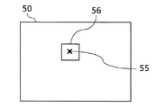
次に、拡大したい部分を指定し、同時に拡大する倍率を指定する。
例えば、図6に示すように、全体の表示領域 50 の拡大したい画像領域部分の中心 55 を指定し、同時に、拡大率を指定する。拡大率の指定は、例えば、キーボード等によって入力する。
例えば、拡大率を2倍に指定すると、図5で設定した拡大部の表示領域の大きさ(矩形の領域 53 の面積)が2倍の表示になる様に計算して、中心 55 から所定の範囲の画像領域を抽出する。
【0019】
拡大表示領域の大きさ、拡大したい画像領域部分(抽出したい画像領域)の大きさ、及び、拡大率は、いずれか2つを指定することによって、他の1つを決定することができる。
例えば、図6において、中心 55′を指定した後、拡大率を入力せず、拡大したい領域 56 の大きさを指定すれば、拡大率が、拡大率=(領域 53 )/(領域 56 の面積)として決定される。また、縦と横の拡大率を個々に設定するために、領域 53 の縦の長さ Y と横の長さ X と領域 56 の縦の長さ y と横の長さ x とから、縦の拡大率= Y / y 、横の拡大率= X / x とを求めることも可能である。
【0020】
即ち、
(1)表示領域全体の大きさに対する拡大部の大きさと倍率を定め、拡大したい領域の中心を指定すると、拡大したい領域の大きさが指定された点を中心にして定まる。
(2)表示領域全体の大きさに対する拡大部の大きさと拡大したい領域の範囲を指定すると、拡大したい倍率が定まる。
(3)倍率と拡大したい領域の範囲を指定すると、表示領域全体の大きさに対する拡大部の大きさが定まる。
【0021】
次に、図7と図8によって、拡大する表示領域と縮小する表示領域の位置決めする方法を説明する。
図7は、拡大したい領域の中心 55′が表示装置に表示された全体の表示領域 50 の中心から外れている場合であっても、電子ズームアップを指定された画像領域の中心 55′と全体の表示領域 50 の左右の端からの距離、及び、上下の端からの距離が同じになるように、拡大領域の横方向及び縦方向の位置決めを行なうことを説明する図である。
即ち、拡大表示画面領域 56′の位置は、電子ズーム指定された領域の中心 55′と前記全体の表示領域 50 との相対的位置に応じて決定する。
図7において、中心 55′から拡大表示領域 56′の左端までの距離 xa 、右端までの距離 xb 、上端までの距離 yb 、下端までの距離 ya と、中心 55′から全体の表示領域 50 の左端までの距離 XA 、右端までの距離 XB 、上端までの距離 YB 、下端までの距離 YA との間には、
XA:XB = xa:xb
YA:YB = ya:yb
が成り立つように配分している。
【0022】
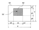
次に、図8は本発明の他の実施例で、拡大したい領域の中心 55′を基準に指定された倍率で拡大領域に入らない部分は全て縮小表示される場合を示す。図8では、指定された中心 55′と表示領域 50 の左右の端からの距離、及び、上下の端からの距離が同じになるように、拡大領域 56′の横方向及び縦方向の位置決めを行なうことを説明する図である。
即ち、中心 55′から拡大表示領域 56′の上下の距離 yL 、拡大表示領域 56′の上端から全体の表示領域 50 の上端までの距離 y1 、拡大表示領域 56′の下端から全体の表示領域 50 の下端までの距離 y0 と、全体の表示領域 50 の上端から下端までの距離 Y とすると、縮小領域の倍率は、
縮小領域の倍率 = ( y0 + y1 )/〔( y0 + y1 )+{ yL ×(拡大領域の拡大率-1 )/ 拡大領域の拡大率 }〕
となる。
例えば、拡大表示領域 56′の全体の表示領域 50 に対する面積比を 25 %(長さ比で 50 %)とすると、拡大率が 2 倍のとき、

【0023】
【発明の効果】
本発明によれば、ズームアップを行なった場合でも、視野角が狭くなることがなく、観測者が被写体の位置関係を確認し易い、映像信号が得られるテレビジョンカメラを提供することができる。
【図面の簡単な説明】
【図1】 本発明の一実施例のテレビジョンカメラ装置の構成を示すブロック図。
【図2】 本発明の一実施例の映像のイメージを示す図。
【図3】 従来のズームアップ時の画像のイメージを示す図。
【図4】 本発明の第2の実施例の映像のイメージを示す図。
【図5】 本発明の拡大部の表示エリアのサイズ設定の一実施例を説明する図。
【図6】 本発明の拡大したい所望の画像エリア部分の指定の一実施例を説明する図。
【図7】 本発明の拡大する表示エリアと縮小する表示エリアの位置決めする方法についての一実施例を説明するための図。
【図8】 本発明の拡大する表示エリアと縮小する表示エリアの位置決めする方法についての一実施例を説明するための図。
【符号の説明】
1:レンズ、 2:撮像素子、 3:CDS・LPF 回路、4:AGC 回路、 5:信号処理回路、 6:画像メモリ、 7:拡大・縮小処理部、 8:CPU、 10:画像、 11,12,13,14,11′,12′,13′,14′,12″,13″:人物、 20,20′,30,30′:画像、 21,22,22′,22″:領域、 50:全体の表示領域、 51,52:点、 53:領域、 55,55′:中心、 56,56′:拡大表示領域、 100:信号出力部。[0001]
BACKGROUND OF THE INVENTION
The present invention relates to a television camera apparatus that can output a single video signal without impairing the viewing angle even when zooming in with an electronic zoom function.
[0002]
[Prior art]
Conventionally, when an image captured by a television camera device such as a monitoring camera is remotely observed on a display device such as a monitor, a desired arbitrary area of the image displayed on the display device is enlarged by zooming up. Sometimes. For example, an observer who is observing with a display device installed in a remote place (for example, a security room), who is the person in the image displayed on the display device, and what facial expression There are times when you want to check information such as. At this time, the monitoring person zooms up by remote control by designating the location of the person's face on the control console (for example, a personal computer), the enlargement ratio, and the like.
The television camera device and the display device are connected to the control console via RS-232C or LAN (Local Area Network).
[0003]
FIG. 3 is a diagram illustrating an image of a conventional zoom-up image. (a) is an
When the enlarged image 20 was copied to the display device, the supervisor wants to know, for example, what the
[0004]
If you need to see the image 20 magnified by zooming up and the entire wide-
(1) Method to output zoomed-in image 20 and wide-
[Problems to be solved by the invention]
The conventional television camera apparatus has the following drawbacks: (1) In the method of outputting two signals of a zoomed-up image and a wide-angle image, two displays are displayed for one camera. Equipment is required and is not efficient.
(2) In the method in which one of the zoomed-up image and the wide-angle image is fitted, the boundary between the two synthesized images is not spatially continuous, so the observer grasps the positional relationship between the two images. Hateful.
An object of the present invention is to provide a television camera device that eliminates the above-described drawbacks and that can obtain a wide-angle image without narrowing the viewing angle even when zooming up.
[0006]
[Means for Solving the Problems]
In order to achieve the above object, the television camera apparatus of the present invention photoelectrically converts an image input through a lens, digitizes and processes the photoelectrically converted signal, and further processes the digitized image. It has a function that can arbitrarily change the image size of a signal or a fixed area, and if the desired area is enlarged by zooming up, the surrounding area is reduced and the image size is the same as that before zooming up Thus, even when zooming up is performed, a video signal having the same viewing angle as that when zooming up is not performed can be output.
[0007]
That is, the image display method of the present invention enlarges a desired area of the acquired image and reduces a part or all of the area other than the enlarged desired area, and the enlarged image and the reduced area. The displayed image is displayed on the display screen.
In the image display method of the present invention, the acquired image is specified by designating a center of the desired area, an enlargement ratio, and a size of a display area of the display screen on which the enlarged image is displayed. The desired area is electronically zoomed up and displayed in the display area of the display screen.
Further, the image display method of the present invention specifies a desired area of the acquired image by designating a range of the desired area and a size of a display area of the display screen on which the enlarged image is displayed. Electronic zoom-in is performed and the display area is displayed on the display screen.
In the image display method of the present invention, the desired area of the acquired image is electronically zoomed up and displayed in the display area of the display screen by designating an enlargement ratio and the range of the desired area. To do.
[0008]
In the image display method of the present invention, the position of the display area of the display screen that displays the enlarged image is determined according to the relative position between the center of the desired area and the entire display area. Is.
In the image display method of the present invention, a region other than the desired region is compressed and displayed in the horizontal direction.
In the image display method of the present invention, the region other than the desired region is compressed and displayed in the vertical direction.
In the image display method of the present invention, an area other than the desired area is compressed and displayed in the horizontal direction and the vertical direction.
[0009]
In addition, the television camera device of the present invention includes an image sensor, a signal processing unit that performs image processing on a video signal acquired by the image sensor, an image memory that stores the image processed image data, and the stored image data. A television camera apparatus comprising an enlargement / reduction means for enlarging or reducing a desired area of an image, and a control means for controlling the enlargement / reduction means, wherein the control means is a request for an image acquired by the image sensor. This area is electronically zoomed up, and the other areas are reduced to display the entire acquired image.
[0010]
Further, the image memory of the television camera apparatus of the present invention stores the image processed image data supplied from the signal processing means in a plurality of fields or frames and stores the image data in the enlargement / reduction means. Is output for each screen.
Further, the enlargement / reduction means of the television camera apparatus of the present invention enlarges or reduces the image data for each area.
Further, the enlargement / reduction means of the television camera device of the present invention enlarges the desired area so as to be the same size as the image size of the image data stored in the image memory, and an area other than the desired area The video data reduced in size is output.
The television camera apparatus of the present invention further includes a signal output means, and changes the video data output from the enlargement / reduction means to a VBS or 4: 2: 2 digital signal for output. .
[0011]
DETAILED DESCRIPTION OF THE INVENTION
An embodiment of a television camera according to the present invention will be described with reference to FIGS. FIG. 1 is a block diagram showing a configuration of a television camera apparatus according to an embodiment of the present invention. 1 is a lens, 2 is an image sensor, 3 is a CDS / LPF circuit, 4 is a gain control (AGC) circuit, 5 is a signal processing circuit, 6 is an image memory, 7 is an enlargement / reduction processing unit, and 8 is a CPU (Central Processing) Unit), 100 is a signal output unit. The
[0012]
In FIG. 1, incident light from a subject passes through a
[0013]
The
Further, the CPU 8 controls the
[0014]
FIG. 2 is a diagram showing an image at the time of electronic zoom-up (enlargement) according to an embodiment of the present invention.
FIG. 2 (a) is an
[0015]
In the example of FIG. 2, only the horizontal direction is compressed, and the vertical direction is not compressed. However, it is possible to compress the vertical and horizontal directions at the same time, or to compress only in the vertical direction, and the supervisor can freely select them.
FIG. 4 is a diagram showing a second embodiment of the present invention, which is an embodiment in which an area that is not enlarged and displayed is compressed in the vertical direction.
FIG. 4 (a) is an
In the
[0016]
Next, referring to FIGS. 5 to 8, an example in which a desired image area portion is enlarged (electronic zoom-up) will be described.
FIG. 5 is a diagram for explaining an embodiment in which the size of the display area of the enlarged portion is set in the present invention. FIG. 6 is a diagram in the case of specifying a desired image area portion to be enlarged in the present invention. It is a figure explaining one Example.
FIGS. 7 and 8 are diagrams for explaining an embodiment of a method for positioning a display area to be enlarged and a display area to be reduced in the present invention, respectively. 5 to 8, images transmitted from the monitoring camera device are omitted from the display area.
[0017]
First, the monitoring person operates the control console to set the size of the display area for displaying the enlarged portion.
As shown in FIG. 5, for the
That is, the
[0018]
Next, the part to be enlarged is designated, and the magnification to be enlarged at the same time is designated.
For example, as shown in FIG. 6, the
For example, if the enlargement ratio is specified to be double, the display area size (area of the rectangular area 53) set in FIG. Extract the image area of the range.
[0019]
By specifying any two of the size of the enlarged display region, the size of the image region portion to be enlarged (image region to be extracted), and the enlargement ratio, the other one can be determined.
For example, in FIG. 6, after designating the center 55 ', if the size of the
[0020]
That is,
(1) When the size and magnification of the enlargement portion with respect to the entire display area are determined and the center of the area to be enlarged is designated, the size of the area to be enlarged is determined around the designated point.
(2) When the size of the enlarged portion and the range of the area to be enlarged are specified with respect to the entire display area, the magnification to be enlarged is determined.
(3) When the magnification and the range of the area to be enlarged are designated, the size of the enlarged portion relative to the size of the entire display area is determined.
[0021]
Next, a method of positioning the display area to be enlarged and the display area to be reduced will be described with reference to FIGS.
FIG. 7 shows the case where the center 55 'of the region to be enlarged is deviated from the center of the
That is, the position of the enlarged
In FIG. 7, the distance xa from the center 55 'to the left edge of the enlarged display area 56', the distance xb to the right edge, the distance yb to the upper edge, the distance ya to the lower edge, and the left edge of the
XA: XB = xa: xb
YA: YB = ya: yb
Is distributed so that
[0022]
Next, FIG. 8 shows another embodiment of the present invention, and shows a case where all the portions that do not enter the enlarged region at the specified magnification with reference to the center 55 'of the region to be enlarged are reduced and displayed. In FIG. 8, the horizontal and vertical positioning of the
That is, the vertical distance yL of the
Reduced area magnification = (y0 + y1) / [(y0 + y1) + {yL × (enlargement area enlargement ratio-1) / enlargement area enlargement ratio}]
It becomes.
For example, if the area ratio of the
[0023]
【The invention's effect】
According to the present invention, it is possible to provide a television camera capable of obtaining a video signal that does not narrow a viewing angle and allows an observer to easily confirm the positional relationship of a subject even when zooming up.
[Brief description of the drawings]
FIG. 1 is a block diagram illustrating a configuration of a television camera apparatus according to an embodiment of the present invention.
FIG. 2 is a diagram showing an image of an image according to an embodiment of the present invention.
FIG. 3 is a diagram illustrating an image of a conventional zoom-up image.
FIG. 4 is a diagram showing an image of a video according to a second embodiment of the present invention.
FIG. 5 is a diagram for explaining an embodiment of setting the size of the display area of the enlarged portion according to the present invention.
FIG. 6 is a diagram for explaining an embodiment of specifying a desired image area portion to be enlarged according to the present invention.
FIG. 7 is a diagram for explaining an embodiment of a method of positioning a display area to be enlarged and a display area to be reduced according to the present invention.
FIG. 8 is a diagram for explaining an embodiment of a method for positioning a display area to be enlarged and a display area to be reduced according to the present invention.
[Explanation of symbols]
1: Lens, 2: Image sensor, 3: CDS / LPF circuit, 4: AGC circuit, 5: Signal processing circuit, 6: Image memory, 7: Enlargement / reduction processing unit, 8: CPU, 10: Image, 11, 12, 13, 14, 11 ', 12', 13 ', 14', 12 ", 13": person, 20, 20 ', 30, 30': image, 21, 22, 22 ', 22 ": area, 50: Overall display area, 51, 52: Point, 53: Area, 55, 55 ': Center, 56, 56': Enlarged display area, 100: Signal output section.
Claims (2)
前記制御手段は、前記撮像素子が取得した画像を前記指定手段で指定した中心点を中心に前記指定した領域を前記指定した拡大率で電子ズームアップし、かつ、前記指定手段で指定した領域以外の領域を前記撮像素子が取得した画像の視野角を狭めることなく縮小し、前記取得した画像の全体を画像表示手段で表示することを特徴とするテレビジョンカメラ装置。Image sensor, signal processing means for image processing of video signal acquired by image sensor, image memory for storing image processed image data, and enlargement for enlarging or reducing a desired area of the stored image A television camera apparatus comprising: a reduction means; a control means for controlling the enlargement / reduction means; and a designation means for designating the desired area, a center point of the area to be enlarged, and an enlargement ratio,
The control means electronically zooms up the designated area around the center point designated by the designation means with respect to the image acquired by the imaging device at the designated magnification, and other than the area designated by the designation means The television camera apparatus is characterized in that the area is reduced without narrowing the viewing angle of the image acquired by the image sensor, and the entire acquired image is displayed by image display means .
Priority Applications (1)
| Application Number | Priority Date | Filing Date | Title |
|---|---|---|---|
| JP2001360338A JP4298947B2 (en) | 2001-11-27 | 2001-11-27 | Image display method and television camera apparatus |
Applications Claiming Priority (1)
| Application Number | Priority Date | Filing Date | Title |
|---|---|---|---|
| JP2001360338A JP4298947B2 (en) | 2001-11-27 | 2001-11-27 | Image display method and television camera apparatus |
Publications (3)
| Publication Number | Publication Date |
|---|---|
| JP2003163836A JP2003163836A (en) | 2003-06-06 |
| JP2003163836A5 JP2003163836A5 (en) | 2005-07-07 |
| JP4298947B2 true JP4298947B2 (en) | 2009-07-22 |
Family
ID=19171171
Family Applications (1)
| Application Number | Title | Priority Date | Filing Date |
|---|---|---|---|
| JP2001360338A Expired - Fee Related JP4298947B2 (en) | 2001-11-27 | 2001-11-27 | Image display method and television camera apparatus |
Country Status (1)
| Country | Link |
|---|---|
| JP (1) | JP4298947B2 (en) |
Families Citing this family (4)
| Publication number | Priority date | Publication date | Assignee | Title |
|---|---|---|---|---|
| KR100539774B1 (en) * | 2002-10-16 | 2006-01-10 | 엘지전자 주식회사 | Wide angle photographing method for digital video system |
| JP2005077821A (en) * | 2003-09-01 | 2005-03-24 | Casio Comput Co Ltd | Apparatus and method for projection, and program |
| JP2006078664A (en) * | 2004-09-08 | 2006-03-23 | Sharp Corp | Device and method for document display, program for making computer function as document display device, and recording medium with this program stored therein |
| JPWO2009141951A1 (en) * | 2008-05-19 | 2011-09-29 | パナソニック株式会社 | Video photographing apparatus and video encoding apparatus |
-
2001
- 2001-11-27 JP JP2001360338A patent/JP4298947B2/en not_active Expired - Fee Related
Also Published As
| Publication number | Publication date |
|---|---|
| JP2003163836A (en) | 2003-06-06 |
Similar Documents
| Publication | Publication Date | Title |
|---|---|---|
| JP6587113B2 (en) | Image processing apparatus and image processing method | |
| US7732771B2 (en) | Monitoring apparatus | |
| JP3938127B2 (en) | Imaging device | |
| US7459685B2 (en) | Imaging device and method, computer program product on computer-readable medium, and imaging system | |
| JP3265893B2 (en) | Image display device | |
| EP1536633A1 (en) | Photographing apparatus and method, supervising system, program and recording medium | |
| US20010024233A1 (en) | Camera control system, camera server, camera client, control method, and storage medium | |
| EP2722831A2 (en) | Linking-up photographing system and control method for linked-up cameras thereof | |
| CN110324572B (en) | Monitoring system, monitoring method, and non-transitory computer-readable storage medium | |
| US6769131B1 (en) | Image processing apparatus and method, image distribution system and storage medium | |
| JP4378636B2 (en) | Information processing system, information processing apparatus, information processing method, program, and recording medium | |
| KR20120108747A (en) | Monitoring camera for generating 3 dimensional scene and method thereof | |
| JP4736381B2 (en) | Imaging apparatus and method, monitoring system, program, and recording medium | |
| KR101778744B1 (en) | Monitoring system through synthesis of multiple camera inputs | |
| JP2000244905A (en) | Video image observation system | |
| JP4583717B2 (en) | Imaging apparatus and method, image information providing system, program, and control apparatus | |
| JP4298947B2 (en) | Image display method and television camera apparatus | |
| JP2000253391A (en) | Panorama video image generating system | |
| JP2004015517A (en) | Video image integrated display device | |
| CN106067941B (en) | System and method for realizing real-time multi-scale imaging by utilizing tiling of camera | |
| JP5509986B2 (en) | Image processing apparatus, image processing system, and image processing program | |
| KR20170055455A (en) | Camera system for compensating distortion of lens using super wide angle camera and Transport Video Interface Apparatus used in it | |
| JP2012034099A (en) | Data transmission device | |
| JP4124995B2 (en) | Video composition apparatus and information processing method | |
| JPH10304227A (en) | Electronic still camera |
Legal Events
| Date | Code | Title | Description |
|---|---|---|---|
| A521 | Request for written amendment filed |
Free format text: JAPANESE INTERMEDIATE CODE: A523 Effective date: 20041101 |
|
| A621 | Written request for application examination |
Free format text: JAPANESE INTERMEDIATE CODE: A621 Effective date: 20041101 |
|
| A977 | Report on retrieval |
Free format text: JAPANESE INTERMEDIATE CODE: A971007 Effective date: 20070209 |
|
| A131 | Notification of reasons for refusal |
Free format text: JAPANESE INTERMEDIATE CODE: A131 Effective date: 20070220 |
|
| A521 | Request for written amendment filed |
Free format text: JAPANESE INTERMEDIATE CODE: A523 Effective date: 20070420 |
|
| A131 | Notification of reasons for refusal |
Free format text: JAPANESE INTERMEDIATE CODE: A131 Effective date: 20080129 |
|
| A521 | Request for written amendment filed |
Free format text: JAPANESE INTERMEDIATE CODE: A523 Effective date: 20080326 |
|
| TRDD | Decision of grant or rejection written | ||
| A01 | Written decision to grant a patent or to grant a registration (utility model) |
Free format text: JAPANESE INTERMEDIATE CODE: A01 Effective date: 20090414 |
|
| A01 | Written decision to grant a patent or to grant a registration (utility model) |
Free format text: JAPANESE INTERMEDIATE CODE: A01 |
|
| A61 | First payment of annual fees (during grant procedure) |
Free format text: JAPANESE INTERMEDIATE CODE: A61 Effective date: 20090416 |
|
| R150 | Certificate of patent or registration of utility model |
Free format text: JAPANESE INTERMEDIATE CODE: R150 |
|
| FPAY | Renewal fee payment (event date is renewal date of database) |
Free format text: PAYMENT UNTIL: 20120424 Year of fee payment: 3 |
|
| FPAY | Renewal fee payment (event date is renewal date of database) |
Free format text: PAYMENT UNTIL: 20130424 Year of fee payment: 4 |
|
| LAPS | Cancellation because of no payment of annual fees |