JP4298552B2 - In-cylinder pressure detector - Google Patents
In-cylinder pressure detector Download PDFInfo
- Publication number
- JP4298552B2 JP4298552B2 JP2004071237A JP2004071237A JP4298552B2 JP 4298552 B2 JP4298552 B2 JP 4298552B2 JP 2004071237 A JP2004071237 A JP 2004071237A JP 2004071237 A JP2004071237 A JP 2004071237A JP 4298552 B2 JP4298552 B2 JP 4298552B2
- Authority
- JP
- Japan
- Prior art keywords
- cylinder pressure
- drift
- change rate
- pcyl
- pressure sensor
- Prior art date
- Legal status (The legal status is an assumption and is not a legal conclusion. Google has not performed a legal analysis and makes no representation as to the accuracy of the status listed.)
- Expired - Fee Related
Links
Images


Landscapes
- Measuring Fluid Pressure (AREA)
- Combined Controls Of Internal Combustion Engines (AREA)
Description
この発明は、内燃機関の筒内圧を検出する装置に関し、より具体的には、検出される筒内圧のドリフトを補正して、より正確な筒内圧を検出する筒内圧検出装置に関する。 The present invention relates to an apparatus for detecting an in-cylinder pressure of an internal combustion engine. More specifically, the present invention relates to an in-cylinder pressure detection apparatus that corrects a drift of a detected in-cylinder pressure and detects a more accurate in-cylinder pressure.
従来、内燃機関のシリンダ(気筒)には、該シリンダ内の圧力(以下、筒内圧と呼ぶ)を検出する筒内圧センサが設けられる。該センサにより検出される筒内圧は、内燃機関の制御に用いられる。 Conventionally, a cylinder (cylinder) of an internal combustion engine is provided with an in-cylinder pressure sensor that detects a pressure in the cylinder (hereinafter referred to as an in-cylinder pressure). The in-cylinder pressure detected by the sensor is used for controlling the internal combustion engine.
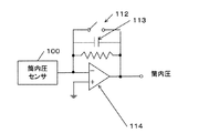
筒内圧センサとして、圧電素子を用いたセンサが知られている。このセンサは、筒内圧の変化率を検出する。図22に示されるように、筒内圧センサ100により検出された筒内圧の変化率は、典型的には積分回路101により積分される。該積分回路101の出力が、筒内圧として用いられる。
A sensor using a piezoelectric element is known as an in-cylinder pressure sensor. This sensor detects the rate of change of in-cylinder pressure. As shown in FIG. 22, the change rate of the in-cylinder pressure detected by the in-
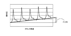
圧電素子を用いた場合、一般に、筒内圧の変化と、筒内圧センサの出力との間の関係に、ヒステリシス特性が存在する。また、圧電素子の温度上昇に伴って、筒内圧センサの出力も上昇する。このような筒内圧センサを内燃機関に搭載すると、内燃機関から発生する熱に依存して、筒内圧センサの出力にバラツキが生じる。その結果、積分回路から出力される筒内圧の波形に、図23に示すような“ずれ”すなわちドリフトが生じるおそれがある。 When a piezoelectric element is used, there is generally a hysteresis characteristic in the relationship between the change in the in-cylinder pressure and the output of the in-cylinder pressure sensor. Further, as the temperature of the piezoelectric element increases, the output of the in-cylinder pressure sensor also increases. When such an in-cylinder pressure sensor is mounted on an internal combustion engine, the output of the in-cylinder pressure sensor varies depending on the heat generated from the internal combustion engine. As a result, the in-cylinder pressure waveform output from the integration circuit may cause “deviation”, that is, drift as shown in FIG.
このようなドリフトが生じると、筒内圧を正確に検出することが困難となる。また、筒内圧センサの出力は、典型的に、その後のコンピュータ処理のためにアナログデジタル(A/D)変換される。筒内圧センサの出力にドリフト成分が含まれると、アナログ値である該筒内圧センサの出力と、該出力をA/D変換した後のデジタル値との間に相関性が失われるおそれがある。 When such a drift occurs, it becomes difficult to accurately detect the in-cylinder pressure. Also, the output of the in-cylinder pressure sensor is typically analog to digital (A / D) converted for subsequent computer processing. When a drift component is included in the output of the in-cylinder pressure sensor, there is a possibility that the correlation is lost between the output of the in-cylinder pressure sensor that is an analog value and the digital value after the A / D conversion of the output.
以下の特許文献1には、このようなドリフトを補正する技術として、積分回路をリセットする手法が開示されている。図24を参照すると、各燃焼サイクルの所定のタイミングで、スイッチング素子112を閉じる。該素子を閉じると、コンデンサ113の前後の電位差が無くなり、よって演算増幅器114の出力が基準値にリセットされる。このリセット操作に応じて、ドリフトが除去される。
図25には、上記のようなリセット操作を行った場合の、積分回路から出力される筒内圧波形が示されている。リセット操作は、時間t1、t2、t3、t4およびt5において実施される。このようなリセット操作に起因する波形115が、筒内圧波形に重畳されていることがわかる。その結果、リセット操作の前後で、筒内圧波形に不連続な周波数特性が現れる。このような不連続な周波数特性により、筒内圧を用いたその後のコンピュータ処理に、不所望の周波数成分が混入される。これは、内燃機関の制御の精度を低下させる。また、このようなリセット操作を行っても、リセット操作とリセット操作の間、すなわち1燃焼サイクル中は、ドリフトが増大する。
FIG. 25 shows an in-cylinder pressure waveform output from the integration circuit when the reset operation as described above is performed. The reset operation is performed at times t1, t2, t3, t4 and t5. It can be seen that the
したがって、このようなリセット操作を行うことなく、検出される筒内圧にドリフトが現れないようにする手法が必要とされている。 Therefore, there is a need for a technique for preventing drift in the detected in-cylinder pressure without performing such a reset operation.
この発明の一つの側面によると、筒内圧検出装置は、内燃機関の筒内圧の変化率に応じた信号を出力する筒内圧センサと、該筒内圧センサの出力信号を補正する補正手段と、該補正手段からの出力を積分して、筒内圧を算出する積分手段と、該筒内圧に基づいて、該筒内圧に含まれるドリフトの変化率を算出するドリフト変化率算出手段と、を備える。該算出されたドリフト変化率は、補正手段にフィードバックされ、該補正手段は、該ドリフト変化率で、筒内圧センサの出力信号を補正する。 According to one aspect of the present invention, an in-cylinder pressure detecting device includes: an in-cylinder pressure sensor that outputs a signal corresponding to a rate of change in an in-cylinder pressure of an internal combustion engine; Integrating means for integrating the output from the correcting means to calculate the in-cylinder pressure; and drift change rate calculating means for calculating the change rate of drift included in the in-cylinder pressure based on the in-cylinder pressure. The calculated drift change rate is fed back to the correction unit, and the correction unit corrects the output signal of the in-cylinder pressure sensor with the drift change rate.
この発明の一実施形態によると、上記のドリフト変化率算出手段は、さらに、上記の算出された筒内圧を、所定のサイクルでサンプリングする。該サンプリングした筒内圧に基づいて、ドリフト量を算出する。該ドリフト量に基づいて、上記ドリフト変化率を算出する。ドリフト量の算出は、該サンプリングした筒内圧から所定の基準値を減算することにより行うことができる。 According to one embodiment of the present invention, the drift change rate calculation means further samples the calculated in-cylinder pressure in a predetermined cycle. A drift amount is calculated based on the sampled in-cylinder pressure. The drift change rate is calculated based on the drift amount. The drift amount can be calculated by subtracting a predetermined reference value from the sampled in-cylinder pressure.
この発明の他の実施形態によると、上記のドリフト変化率算出手段は、さらに、上記の算出された筒内圧を、第1のサイクルでサンプリングする。該サンプリングした筒内圧に基づいて、ドリフト量を算出する。該ドリフト量を、第1のサイクルよりも短い第2のサイクルでサンプリングし、該ドリフト量のサンプル値を生成する。該ドリフト量のサンプル値を平均して、該第2のサイクルあたりのドリフト量を算出する。該第2のサイクルあたりのドリフト量に基づいて、上記ドリフト変化率を算出する。ドリフト量の算出は、該サンプリングした筒内圧から所定の基準値を減算することにより行うことができる。 According to another embodiment of the present invention, the drift change rate calculation means further samples the calculated in-cylinder pressure in the first cycle. A drift amount is calculated based on the sampled in-cylinder pressure. The drift amount is sampled in a second cycle shorter than the first cycle, and a sample value of the drift amount is generated. The drift amount per second cycle is calculated by averaging the sample values of the drift amount. The drift change rate is calculated based on the drift amount per second cycle. The drift amount can be calculated by subtracting a predetermined reference value from the sampled in-cylinder pressure.
この発明の一実施形態によると、筒内圧検出装置は、さらに、上記のドリフト変化率算出手段および上記補正手段の間に、制御手段を備える。該制御手段は、上記のドリフト変化率をゼロに収束させるように、ドリフト補正項を算出する。補正手段は、該ドリフト補正項で、筒内圧センサの出力信号を補正する。一実施形態では、制御手段は、ドリフト変化率のゼロへの収束速度を指定可能な応答指定型制御を用いて、該ドリフト補正項を算出する。 According to one embodiment of the present invention, the in-cylinder pressure detection apparatus further includes a control unit between the drift change rate calculation unit and the correction unit. The control means calculates a drift correction term so that the drift change rate converges to zero. The correction means corrects the output signal of the in-cylinder pressure sensor with the drift correction term. In one embodiment, the control means calculates the drift correction term by using a response designation type control capable of designating a convergence rate of the drift change rate to zero.
この発明によると、リセット操作を行うことなくドリフト成分を除去することができるので、筒内圧波形に不連続な周波数特性が現れるのを防ぐことができる。 According to the present invention, since the drift component can be removed without performing the reset operation, it is possible to prevent a discontinuous frequency characteristic from appearing in the in-cylinder pressure waveform.
この発明によると、所定の時間間隔で、筒内圧に含まれるドリフト成分をフィードバックし、該フィードバックしたドリフト成分を、筒内圧センサの出力から除去する。ドリフト成分を除去するよう補正された筒内圧センサの出力を用いることにより、筒内圧センサの出力と、該出力をA/D変換した後のデジタル値との間の相関性が維持される。ドリフト成分を除去するよう補正された筒内圧センサの出力を積分するので、該積分により得られる筒内圧においてドリフトが増大するのを回避することができる。 According to the present invention, the drift component included in the in-cylinder pressure is fed back at predetermined time intervals, and the fed back drift component is removed from the output of the in-cylinder pressure sensor. By using the output of the in-cylinder pressure sensor corrected to remove the drift component, the correlation between the output of the in-cylinder pressure sensor and the digital value after A / D conversion of the output is maintained. Since the output of the in-cylinder pressure sensor corrected so as to remove the drift component is integrated, it is possible to avoid an increase in drift in the in-cylinder pressure obtained by the integration.
次に図面を参照してこの発明の実施の形態を説明する。図1は、この発明の実施形態に従う、内燃機関(以下、エンジンと呼ぶ)およびその制御装置の全体的な構成図である。 Next, an embodiment of the present invention will be described with reference to the drawings. FIG. 1 is an overall configuration diagram of an internal combustion engine (hereinafter referred to as an engine) and its control device according to an embodiment of the present invention.
電子制御ユニット(以下、「ECU」)という)1は、車両の各部から送られてくるデータを受け入れる入力インターフェース1a、車両の各部の制御を行うための演算を実行するCPU1b、読み取り専用メモリ(ROM)およびランダムアクセスメモリ(RAM)を有するメモリ1c、および車両の各部に制御信号を送る出力インターフェース1dを備えている。メモリ1cのROMには、車両の各部の制御を行うためのプログラムおよび各種のデータが格納されている。この発明に従う筒内圧検出のためのプログラムは、該ROMに格納される。ROMは、EPROMのような書き換え可能なROMでもよい。RAMには、CPU1bによる演算のための作業領域が設けられる。車両の各部から送られてくるデータおよび車両の各部に送り出す制御信号は、RAMに一時的に記憶される。
An electronic control unit (hereinafter referred to as “ECU”) 1 includes an
エンジン2は、たとえば4サイクルのエンジンである。エンジン2は、可変圧縮比機構を備えたものでもよい。 The engine 2 is, for example, a 4-cycle engine. The engine 2 may include a variable compression ratio mechanism.
エンジン2は、吸気弁3を介して吸気管4に連結され、排気弁5を介して排気管6に連結されている。吸気弁3および排気弁5は、連続可変動弁系でもよい。ECU1からの制御信号に従って燃料を噴射する燃料噴射弁7が、吸気管4に設けられている。代替的に、燃料噴射弁7は、燃焼室8に設けられてもよい。
The engine 2 is connected to an intake pipe 4 via an intake valve 3 and connected to an exhaust pipe 6 via an
エンジン2は、吸気管4から吸入される空気と、燃料噴射弁7から噴射される燃料との混合気を、燃焼室8に吸入する。燃料室8には、ECU1からの点火時期信号に従って火花を飛ばす点火プラグ9が設けられている。点火プラグ9によって発せられた火花により、混合気は燃焼する。
The engine 2 sucks an air-fuel mixture of air sucked from the intake pipe 4 and fuel injected from the fuel injection valve 7 into the
筒内圧センサ15は、点火プラグ9のシリンダに接する部分に埋没されている。代替的に、燃料噴射弁7が燃焼室8に設けられる場合には、筒内圧センサ15を、該燃料噴射弁7のシリンダに接する部分に埋没させてもよい。筒内圧センサ15は、燃焼室8内の筒内圧の変化率に応じた信号を生成し、それを、ECU1に送る。
The in-
エンジン2には、クランク角センサ17が設けられている。クランク角センサ17は、クランクシャフト11の回転に伴い、パルス信号であるCRK信号およびTDC信号をECU1に出力する。
The engine 2 is provided with a
CRK信号は、所定のクランク角で出力されるパルス信号である。ECU1は、該CRK信号に応じ、エンジン2の回転数NEを算出する。TDC信号は、ピストン10のTDC位置に関連したクランク角度で出力されるパルス信号である。
The CRK signal is a pulse signal output at a predetermined crank angle. The
エンジン2の吸気管4には、スロットル弁18が設けられている。スロットル弁18の開度は、ECU1からの制御信号により制御される。スロットル弁18に連結されたスロットル弁開度センサ(θTH)19は、スロットル弁18の開度に応じた信号を、ECU1に供給する。
A
吸気管圧力(Pb)センサ20は、スロットル弁18の下流側に設けられている。Pbセンサ20によって検出された吸気管圧力PbはECU1に送られる。
The intake pipe pressure (Pb)
ECU1に向けて送られた信号は入力インターフェース1aに渡され、アナログデジタル(A/D)変換される。CPU1bは、該デジタル信号を、メモリ1cに格納されているプログラムに従って処理し、車両のアクチュエータに送るための制御信号を作り出す。出力インターフェース1dは、これらの制御信号を、燃料噴射弁7、点火プラグ9、スロットル弁18、およびその他の機械要素のアクチュエータに送る。
A signal sent to the
図2は、筒内圧センサ15の取り付けの一例を示す図である。シリンダヘッド21のねじ孔22に点火プラグ9がねじ込まれている。シリンダヘッド21の点火プラグの取り付け座面23と、点火プラグ座金部24との間に、筒内圧センサのセンサ素子部25が、ワッシャ26と共に挟み込まれている。センサ素子部25は、圧電素子からなる。
FIG. 2 is a diagram illustrating an example of attachment of the in-
センサ素子部25は、点火プラグ9の座金として締め付けられるので、該センサ素子部25には、所定の締め付け荷重が与えられる。燃焼室8内の圧力が変化すると、該センサ素子部25に印加される荷重が変化する。筒内圧センサ15は、該所定の締め付け荷重に対する荷重の変化を、筒内圧の変化として検出する。
Since the
図3を参照して、本願発明の原理を説明する。図3の(a)は、筒内圧センサ15の出力、すなわち筒内圧の変化率Vpsを示す。
The principle of the present invention will be described with reference to FIG. FIG. 3A shows the output of the in-
筒内圧センサの出力Vpsには、ドリフト成分Δdftが含まれており、式(1)のように表すことができる。 The output Vps of the in-cylinder pressure sensor includes a drift component Δdft, which can be expressed as in Expression (1).
Vps=Vps’+Δdft (1)
筒内圧を検出するため、式(2)に示されるように、筒内圧センサの出力Vpsを積分する。積分により得られる筒内圧Pcylの波形が、図3の(b)に表されている。ライン81に示されるように、Δdftに起因したドリフトが現れている。
![]()
In order to detect the in-cylinder pressure, the output Vps of the in-cylinder pressure sensor is integrated as shown in Expression (2). A waveform of the in-cylinder pressure Pcyl obtained by integration is shown in FIG. As indicated by
![]()
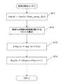
本願発明では、図3の(b)筒内圧波形に現れるドリフト81について、ドリフト変化率Pcyl_compを算出する。該ドリフト変化率Pcyl_compを、図3の(a)に示される、筒内圧の変化率Vpsから減算する。こうして得られた、ドリフト補正済み筒内圧変化率(Vps−Pcyl_comp)を、式(3)に示されるように積分する。

式(3)に式(1)を代入すると、式(4)が得られる。
筒内圧センサの出力に含まれるドリフト成分Δdftは、ドリフト変化率を表している。すなわち、ドリフト成分Δdftは、筒内圧から算出されるドリフト変化率Pcyl_compに等しい。したがって、式(4)は、式(5)のように表される。
このように、筒内圧センサの出力Vpsから、ドリフト変化率Pcyl_compを減算することにより得られる値Vps’を積分すれば、ドリフト成分を含まない筒内圧Pcylを得ることができる。ドリフト成分を含まない筒内圧Pcylの波形を、図3の(c)に示す。 Thus, if the value Vps ′ obtained by subtracting the drift change rate Pcyl_comp from the output Vps of the in-cylinder pressure sensor is integrated, the in-cylinder pressure Pcyl not including the drift component can be obtained. A waveform of the in-cylinder pressure Pcyl not including the drift component is shown in FIG.
図3の(b)のライン81に示すように、ドリフトは、ほぼ線形に変化する。ライン81に基づいて、ドリフト変化率Pcyl_compを求めることができる。
As shown by the
以下に、本願発明に従う、いくつかの実施例を説明する。ドリフトおよび筒内圧についての「変化率」は、所定時間あたりの変化量を表している。以下の実施例では、時間は、クランク角度を用いて計時される。したがって、サンプリングおよび演算等の各処理は、クランク角度に同期するよう行われる。代替的に、他のパラメータを用いて、時間を計時してもよい。また、代替的に、タイマ等を設けて、各処理を所定の時間間隔で行うようにしてもよい。 Several examples according to the present invention will be described below. The “change rate” for drift and in-cylinder pressure represents the amount of change per predetermined time. In the following example, the time is measured using the crank angle. Therefore, each processing such as sampling and calculation is performed in synchronization with the crank angle. Alternatively, the time may be timed using other parameters. Alternatively, a timer or the like may be provided to perform each process at a predetermined time interval.
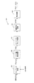
図4は、本発明の第1の実施例に従う、筒内圧検出装置のブロック図である。筒内圧検出装置は、典型的には、ECU1内に実現される。示されるブロックにより実現される機能は、典型的には、コンピュータプログラムにより実現される。代替的に、ハードウェア、ソフトウェア、ファームウェアおよびこれらの組み合わせにより、これらの機能を実現してもよい(以下のブロック図についても同様である)。筒内圧センサ15の出力は、アナログデジタル変換され、Vpsとして筒内圧検出装置に入力される。
FIG. 4 is a block diagram of the in-cylinder pressure detecting device according to the first embodiment of the present invention. The in-cylinder pressure detecting device is typically realized in the
補正装置31は、筒内圧センサ15の出力、すなわち筒内圧の変化率Vpsから、ドリフト変化率Pcyl_compを減算する(上記式(3)を参照)。積分装置32は、こうしてドリフト補正された筒内圧変化率Vps’を積分し、筒内圧Pcylを算出する(上記式(5)を参照)。ドリフト変化率算出装置33は、筒内圧Pcylに基づいて、ドリフト変化率Pcyl_compを算出する。ドリフト変化率Pcyl_compは、ドリフト補正項として、補正装置31にフィードバックされる。
The
このフィードバック操作は、所定の時間間隔で繰り返し行われる。したがって、所定の時間間隔ごとに、筒内圧センサの出力Vpsから、ドリフト成分Pcyl_compが除去される。ドリフト成分が除去された筒内圧センサの出力Vps’を積分するので、得られる筒内圧Pcylの波形に、ドリフトが現れることを抑制することができる。 This feedback operation is repeatedly performed at predetermined time intervals. Therefore, the drift component Pcyl_comp is removed from the output Vps of the in-cylinder pressure sensor at predetermined time intervals. Since the output Vps ′ of the in-cylinder pressure sensor from which the drift component has been removed is integrated, it is possible to suppress the appearance of drift in the waveform of the in-cylinder pressure Pcyl obtained.
この第1の実施例では、ドリフト変化率算出装置33による処理は、1燃焼サイクルの長さに等しいTnの周期で行われ、補正装置31および積分装置32による処理は、Tnよりも短いTkの周期で行われる。好ましくは、Tkは、筒内圧センサの出力をアナログデジタル変換するサイクルの長さに一致するように決められる。こうすることにより、筒内圧センサの出力がデジタル値Vpsとして得られるたびに、該Vpsをドリフト補正項Pcyl_compで補正することができる。
In the first embodiment, the processing by the drift change
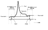
図5は、ドリフト変化率算出装置33の詳細なブロック図である。サンプリング回路35によるサンプリングは、Tnの周期で行われる。サンプリング回路35は、各燃焼サイクルの所定のクランク(CRK)角度で、筒内圧Pcylをサンプリングする。好ましくは、吸気行程中の所定のクランク角度で、筒内圧Pcylをサンプリングする。該サンプリングにより得られた筒内圧サンプルPsampleは、次のサンプリングまでサンプリング回路35に保持される。図6に、筒内圧サンプルPsampleの波形を示す。
FIG. 5 is a detailed block diagram of the drift change
ドリフト量算出回路36は、サンプリング回路35により筒内圧サンプルPsampleが生成されることに応じて、式(6)を実行し、ドリフト量Pdftを算出する。
In response to the in-cylinder pressure sample Psample generated by the
ドリフト量Pdft=筒内圧Psample−基準値 (6)
基準値は、ドリフトの影響がないときの筒内圧を示すように設定される。一例では、基準値として、サンプリング回路35によるサンプリングと同じタイミングでサンプリングされた、吸気管圧力センサ20の出力Pbを用いる。吸気行程中は吸気バルブが開いているので、ドリフトの影響がなければ、筒内圧と吸気管圧力とはほぼ同じ圧力となる。すなわち、筒内圧Pcylから吸気管圧力Pbを減算した値が、該燃焼サイクル中に蓄積されるドリフト量Pdftを表す。
Drift amount Pdft = In-cylinder pressure Psample−reference value (6)
The reference value is set to indicate the in-cylinder pressure when there is no influence of drift. In one example, the output Pb of the intake
図7に、ドリフト量Pdftの一例を示す。第1の燃焼サイクルにおける吸気行程中の時間t1にサンプリングされた筒内圧サンプルPsample1は、次の筒内圧サンプルが得られるまで、サンプリング回路35に保持される。時間t1にサンプリングされた吸気管圧力Pbとの差が、該第1の燃焼サイクルについてのドリフト量Pdft1である。同様に、第2の燃焼サイクルにおける吸気行程中の時間t2にサンプリングされた筒内圧サンプルPsample2が、次の筒内圧サンプルが得られるまで、サンプリング回路35に保持される。時間t2にサンプリングされた吸気管圧力Pbとの差が、該第2の燃焼サイクルについてのドリフト量Pdft2である。こうして、燃焼サイクルごとに、ドリフト量Pdftが算出される。
FIG. 7 shows an example of the drift amount Pdft. The in-cylinder pressure sample Psample1 sampled at time t1 during the intake stroke in the first combustion cycle is held in the
図5に戻り、ドリフト変化率算出回路37は、式(7)を実行し、ドリフト変化率Pcyl_compを算出する。
Returning to FIG. 5, the drift change
ドリフト変化率Pcyl_comp
=ドリフト量Pdft/所定のサンプリング回数 (7)
ここで、所定のサンプリング回数=1燃焼サイクル/Tk
前述したように、一実施例では、Tkは、筒内圧センサの出力をアナログデジタル変換するサイクルの長さに等しい。こうして、時間Tkごとに得られる筒内圧センサの出力Vpsを、時間Tkあたりのドリフト変化率Pcyl_compで補正することができる。
Drift change rate Pcyl_comp
= Drift amount Pdft / predetermined number of samplings (7)
Here, the predetermined number of samplings = 1 combustion cycle / Tk
As described above, in one embodiment, Tk is equal to the length of the cycle for analog-digital conversion of the output of the in-cylinder pressure sensor. In this way, the output Vps of the in-cylinder pressure sensor obtained at every time Tk can be corrected by the drift change rate Pcyl_comp per time Tk.
図8に、ドリフト変化率Pcyl_compを示す。時間t1において、ドリフト量算出回路36がドリフト量Pdftを算出する。該ドリフト量Pdftを、所定のサンプリング回数で除算することにより、時間Tkあたりのドリフト変化率Pcyl_compを算出することができる。こうして算出されたドリフト変化率Pcyl_compが、ドリフト補正項として、補正装置31(図4)にフィードバックされる。
FIG. 8 shows the drift change rate Pcyl_comp. At time t1, the drift
図9は、図5のサンプリング回路35のより詳細な動作を示す図である。図9の(a)は、積分装置32から出力される筒内圧Pcylを示す。
FIG. 9 is a diagram showing a more detailed operation of the
サンプリング回路35は、アップカウンタを備える。アップカウンタの値Dcntが、図9の(b)に示されている。アップカウンタは、各燃焼サイクルの吸気行程中の開始時点、すなわちクランク角度がゼロになった時に、ゼロにリセットされる。アップカウンタは、クランク角センサ17(図1)からのクランク信号に従ってカウントする。
The
一実施例では、クランク信号は、クランク軸が1度回転するたびに出力される。1燃焼サイクル中、クランク信号は720回出力される。よってアップカウンタは、各燃焼サイクルにおいて、0から720までカウントする。
In one embodiment, the crank signal is output every time the crankshaft rotates once. The crank signal is
図9の(b)には、さらに、筒内圧Pcylをサンプリングすべきクランク角度Dsampleを示す波形が示されている。該クランク角度Dsampleの値は、予め決められている。サンプリング回路35は、アップカウンタの値Dcntと、該クランク角度Dsampleとを比較する。
FIG. 9B further shows a waveform indicating the crank angle Dsample where the in-cylinder pressure Pcyl should be sampled. The value of the crank angle Dsample is determined in advance. The
図9の(c)に示されるように、アップカウンタの値Dcntがクランク角度Dsampleに一致した時、所定値(たとえば、1)を持つサンプル信号Tsampleを出力する。アップカウンタの値Dcntが所定値Dsampleに一致しない時は、ゼロ値を持つサンプル信号Tsampleが生成される。 As shown in FIG. 9C, when the value Dcnt of the up counter matches the crank angle Dsample, a sample signal Tsample having a predetermined value (for example, 1) is output. When the value Dcnt of the up counter does not match the predetermined value Dsample, a sample signal Tsample having a zero value is generated.
図9の(d)に示すように、所定値を持つサンプル信号Tsampleが出力されることに応じて、サンプリング回路35は筒内圧Pcylをサンプリングし、筒内圧サンプルPsampleを得る。ゼロ値を持つサンプル信号Tsampleが出力されている間は、該筒内圧サンプルPsampleがサンプリング回路35に保持される。前述したように、燃焼サイクルの長さに等しいTnの周期で、筒内圧サンプルPsampleは生成される。
As shown in FIG. 9D, in response to the output of the sample signal Tsample having a predetermined value, the
図10は、図4に示されるドリフト変化率算出装置33についての代替形態を示す。サンプリング回路35およびドリフト量算出回路36は、図5に示されるものと同じである。図5に示されるドリフト変化率算出装置と異なる点は、ドリフト量Pdftからドリフト変化率Pcyl_compを算出する手法である。
FIG. 10 shows an alternative form of the drift change
第2の実施例によると、オーバーサンプリング、移動平均、および微分という一連の操作により、ドリフト変化率Pcyl_compを算出する。この手法について、図11を参照して説明する。 According to the second embodiment, the drift change rate Pcyl_comp is calculated by a series of operations of oversampling, moving average, and differentiation. This method will be described with reference to FIG.
図11の(a)には、各燃焼サイクルにおいて(すなわち、Tnの周期で)ドリフト量算出回路36により算出されたドリフト量Pdftの波形が示されている。オーバーサンプリング回路41は、Tkの周期で、ドリフト量Pdftをオーバーサンプリングする。
FIG. 11A shows a waveform of the drift amount Pdft calculated by the drift
1燃焼サイクルにおけるサンプリング回数mは、(1燃焼サイクル/Tk)である。図11の(a)には、m=6の例が示されている。 The sampling number m in one combustion cycle is (1 combustion cycle / Tk). FIG. 11A shows an example of m = 6.
移動平均回路42は、オーバーサンプリングによってサンプル値が得られるたびに、式(8)に従い、サンプルPdft(k−(m−1))〜Pdft(k)を平均する。こうして、時間Tkあたりのドリフト量ΔPdftを算出する。
こうして得られるドリフト量ΔPdftは、図11の(b)に示されるようなラインで表される。該ドリフト量ΔPdftは、時間Tkあたりに蓄積されるドリフト量を示す。したがって、図11の(b)に示されるラインの傾きを求めることにより、すなわち該ドリフト量ΔPdftを微分することにより、ドリフト変化率Pcyl_compを算出することができる。 The drift amount ΔPdft obtained in this way is represented by a line as shown in FIG. The drift amount ΔPdft indicates the drift amount accumulated per time Tk. Therefore, the drift change rate Pcyl_comp can be calculated by obtaining the slope of the line shown in FIG. 11B, that is, by differentiating the drift amount ΔPdft.
一例として、m=6の時に時間t1で算出されるドリフト変化率Pcyl_compが示されている。該ドリフト変化率Pcyl_compは、Pdft(k−5)〜Pdft(k)を移動平均することにより得たΔPdftを微分することにより、算出される。こうして、Tkの周期でドリフト変化率Pcyl_compを算出すると、図11の(c)に示されるような波形が得られる。算出されたドリフト変化率Pcyl_compは、ドリフト補正項として、補正装置31(図4)にフィードバックされる。 As an example, the drift change rate Pcyl_comp calculated at time t1 when m = 6 is shown. The drift change rate Pcyl_comp is calculated by differentiating ΔPdft obtained by moving and averaging Pdft (k−5) to Pdft (k). Thus, when the drift change rate Pcyl_comp is calculated at the cycle of Tk, a waveform as shown in FIG. 11C is obtained. The calculated drift change rate Pcyl_comp is fed back to the correction device 31 (FIG. 4) as a drift correction term.
前述したように、Tkは、筒内圧センサの出力をアナログデジタル変換するサイクルの長さに等しい。こうして、Tkの周期で得られる筒内圧センサの出力Vpsを、時間Tkあたりのドリフト変化率Pcyl_compで補正することができる。 As described above, Tk is equal to the length of the cycle for analog-digital conversion of the output of the in-cylinder pressure sensor. In this way, the output Vps of the in-cylinder pressure sensor obtained at the cycle of Tk can be corrected by the drift change rate Pcyl_comp per time Tk.
上記の実施形態では、オーバーサンプリングされたサンプル値の平均に、移動平均法を用いた。代替的に、他のフィルタリング(たとえば、ローパスフィルタ)を用いてもよい。 In the above embodiment, the moving average method is used to average oversampled sample values. Alternatively, other filtering (eg, a low pass filter) may be used.
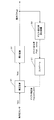
図12は、本願発明の第3の実施例に従う、筒内圧検出装置を示す。図4に示される筒内圧検出装置と異なる点は、補正装置31およびドリフト変化率算出装置33との間に、コントローラ51が設けられることである。ドリフト変化率算出装置33は、第1の実施例に従う図5に示されるものでもよく、また、第2の実施例に従う図10に示されるものでもよい。
FIG. 12 shows an in-cylinder pressure detecting device according to the third embodiment of the present invention. A difference from the in-cylinder pressure detection device shown in FIG. 4 is that a
コントローラ51は、ドリフト変化率算出装置33から受け取ったドリフト変化率Pcyl_cpmpが目標値Pcyl_comp_cmd(この実施例では、ゼロ)に収束するように、ドリフト補正項Pcyl_comp_SLDを算出する。該ドリフト補正項Pcyl_comp_SLDが、制御入力として補正装置31に入力される。補正装置31は、筒内圧センサの出力Vpsにドリフト補正項Pcyl_comp_SLDを加算する。積分装置32は、こうしてドリフト補正された筒内圧センサの出力Vps’を積分し、筒内圧Pcylを算出する。
The
この第3の実施例では、コントローラ51は、燃焼サイクルの長さに等しいTnの周期で応答指定型制御を実施し、ドリフト変化率Pcyl_compを収束させる。代替的に、ドリフト変化率Pcyl_compがTkの周期で算出される第2の実施例では、応答指定型制御を、Tkの周期で実施してもよい。
In this third embodiment, the
応答指定型制御は、制御量(ここでは、ドリフト変化率Pcyl_comp)の目標値への収束速度を指定することができる制御である。応答指定型制御によれば、ドリフト変化率Pcyl_compを、オーバーシュートを生じさせることなく、所望の速度でゼロに収束させることができる。この実施例では、応答指定型制御として、簡易型のスライディングモード制御を用いる。 The response designation type control is a control capable of designating a convergence speed of a control amount (here, drift change rate Pcyl_comp) to a target value. According to the response assignment control, the drift change rate Pcyl_comp can be converged to zero at a desired speed without causing an overshoot. In this embodiment, simple sliding mode control is used as response designation control.
図13は、コントローラ51のさらに詳細なブロック図である。応答指定型制御を実施するため、切り換え関数設定部52は、式(9)に示されるような切り換え関数σを設定する。Encは、式(10)に示されるように、ドリフト変化率Pcyl_compと目標値Pcyl_comp_cmdとの間の偏差を示す。
FIG. 13 is a more detailed block diagram of the
σ(k)=Enc(k)+POLE・Enc(k−1) (9)
Enc(k)=Pcyl_comp(k)−Pcyl_comp_cmd(k)
(10)
POLEは、切換関数σの応答指定パラメータであり、ドリフト変化率Pcyl_compの収束速度を規定する。POLEは、好ましくは、−1<POLE<0を満たすよう設定される。
σ (k) = Enc (k) + POLE · Enc (k−1) (9)
Enc (k) = Pcyl_comp (k) −Pcyl_comp_cmd (k)
(10)
POLE is a response designation parameter of the switching function σ and defines the convergence speed of the drift change rate Pcyl_comp. POLE is preferably set to satisfy -1 <POLE <0.
切換関数σ(k)=0とした式は等価入力系と呼ばれ、ドリフト変化率の収束特性を規定する。σ(k)=0とすると、式(9)は、式(11)のように表されることができる。 The equation with the switching function σ (k) = 0 is called an equivalent input system and defines the convergence characteristic of the drift change rate. When σ (k) = 0, Expression (9) can be expressed as Expression (11).
Enc(k)=−POLE・Enc(k−1) (11)
ここで、図14を参照して、切り換え関数について説明する。縦軸がEnc(k)および横軸がEnc(k−1)の位相平面上に、式(11)が、線61で表現されている。この線61を切換線と呼ぶ。Enc(k−1)およびEnc(k)の組合せからなる状態量(Enc(k−1), Enc(k)))の初期値が、点62で表されているとする。応答指定型制御は、点62で表される状態量を、切換線61上に載せて該切換線61上に拘束するよう動作する。
Enc (k) = − POLE · Enc (k−1) (11)
Here, the switching function will be described with reference to FIG. Expression (11) is represented by a
応答指定型制御によると、状態量62を切換線61上に保持することにより、該状態量を、外乱等の影響されることなく、極めて安定的に位相平面上の原点0に収束させることができる。言い換えると、状態量(Enc(k−1), Enc(k))を、式(11)に示される入力の無い安定系に拘束することにより、外乱に対してロバストに、偏差Encをゼロに収束させることができる。
According to the response designation type control, by holding the
この実施例では、切換関数σに関する位相空間が2次元であるので、切換線は直線61で表される。位相空間が3次元である場合には、切換線は平面で表され、位相空間が4次元以上になると、切換線は超平面となる。
In this embodiment, since the phase space related to the switching function σ is two-dimensional, the switching line is represented by a
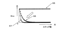
応答指定パラメータPOLEは、可変に設定することができる。応答指定パラメータPOLEを調整することにより、偏差Encの収束速度を指定することができる。 The response designation parameter POLE can be variably set. By adjusting the response designation parameter POLE, the convergence speed of the deviation Enc can be designated.
図15を参照すると、参照番号65、66および67は、応答指定パラメータPOLEが、それぞれ、−1、−0.8、−0.5の場合の偏差Encの収束速度を示す。応答指定パラメータPOLEの絶対値が小さくなるにつれ、偏差Encの収束速度は速くなる。
Referring to FIG. 15,
図13に戻り、到達則算出部53は、式(12)に示されるように、切換関数σの比例項により表される到達則入力Urchを算出する。到達則入力Urchは、状態量を切り換え線上に載せるための入力である。適応則算出部54は、式(13)に示されるように、切換関数σの積算項で表される適応則入力Uadpを算出する。適応則入力Uadpは、定常偏差を抑制しつつ、状態量を切換線に載せるための入力である。KrchおよびKadpは、フィードバックゲインであり、それぞれ、シミュレーション等によって予め定められる。加算器55は、式(14)に示されるように、到達則入力Urchと適応則入力Uadpとを加算する。こうして、制御入力Pcyl_comp_SLDが算出される。
図16および図17を参照して、応答指定型制御を用いた場合の効果について説明する。図16の(a)は、前述した第1または第2の実施例において、ドリフト変化率算出装置33により算出されるドリフト変化率Pcyl_compの波形を示す。図16の(b)は、図16の(a)に示されるドリフト変化率Pcyl_compを積分した波形を示す。符号71〜74に示されるように、ドリフト変化率の演算サイクル間にわたって、波形に不連続さが生じる。これは、ドリフト量Pdftを燃焼サイクルごとに算出することに起因する。すなわち、時間Tnにわたって、算出されるドリフト変化率Pcyl_compが一定であることに起因する。このようなドリフト変化率Pcyl_compで筒内圧センサの出力Vpsを補正すると、積分装置32から出力される筒内圧の波形に、図16(b)に示されるような不連続性が現れるおそれがある。これは、筒内圧波形の周波数分解などの処理において好ましくない。応答指定型制御を用いれば、このような不連続さを解消することができる。
With reference to FIG. 16 and FIG. 17, the effect at the time of using response designation type | mold control is demonstrated. FIG. 16A shows the waveform of the drift change rate Pcyl_comp calculated by the drift change
図17の(a)は、コントローラ51によりドリフト補正項として算出されるPcyl_comp_SLDを示す。図17の(b)は、図17の(a)に示されるドリフト補正項Pcyl_comp_SLDを積分した波形を示す。応答指定型制御により、ドリフト補正項Pcyl_comp_SLDが、漸近的にゼロになるように算出されるので、ドリフト補正項Pcyl_comp_SLDを積分した値が、連続した波形として得られる。ドリフト補正項Pcyl_comp_SLDの積分値が不連続性を持たないので、筒内圧波形に、不所望の不連続性が現れることを回避することができる。
FIG. 17A shows Pcyl_comp_SLD calculated by the
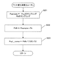
図18は、第3の実施例に従う、筒内圧を検出するプロセスのフローチャートを示す。ドリフト変化率Pcyl_compを算出する処理は、第1の実施例(図5を参照)に従う。このプロセスは、Tkの周期で実施される。 FIG. 18 shows a flowchart of a process for detecting the in-cylinder pressure according to the third embodiment. The processing for calculating the drift change rate Pcyl_comp follows the first embodiment (see FIG. 5). This process is performed with a period of Tk.
ステップS1において、筒内圧センサ15の出力Vpsを読み込む(すなわち、筒内圧センサ15の出力をサンプリングして、デジタル値Vpsを得る)。ステップS2において、ドリフト補正項Pcyl_comp_SLDにより補正した筒内圧センサの出力Vps’を積分して、筒内圧Pcylを算出する。
In step S1, the output Vps of the in-
ステップS3において、アップカウンタ(図9を参照)の値Dcntが、筒内圧をサンプリングすべきクランク角度Dsampleに達したかどうかを判断する。ステップS3の答えがNoならば、筒内圧をサンプリングすべき時が到来していないので、このルーチンを抜ける。 In step S3, it is determined whether the value Dcnt of the up counter (see FIG. 9) has reached the crank angle Dsample where the in-cylinder pressure is to be sampled. If the answer to step S3 is No, the routine is exited because it is not time to sample the in-cylinder pressure.
ステップS3の答えがYesならば、ステップS4に進み、筒内圧Pcylをサンプリングして、ドリフト変化率Pcyl_compを算出する。ステップS4において、簡易型の応答指定型制御を実施し、ドリフト補正項Pcyl_comp_SLDを算出する。 If the answer to step S3 is Yes, the process proceeds to step S4, the in-cylinder pressure Pcyl is sampled, and the drift change rate Pcyl_comp is calculated. In step S4, simple response designation control is performed to calculate a drift correction term Pcyl_comp_SLD.
図19は、ステップS2の処理のフローチャートを示す。ステップS11において、筒内圧センサの出力Vpsに、ドリフト補正項Pcyl_comp_SLDを加算し、ドリフト補正された筒内圧センサの出力Vps’を算出する。 FIG. 19 shows a flowchart of the process of step S2. In step S11, the drift correction term Pcyl_comp_SLD is added to the in-cylinder pressure sensor output Vps to calculate the drift-corrected in-cylinder pressure sensor output Vps'.
ステップS12において、現在の周期Tkが、実際、どのくらいの時間(秒)であるかを計算する。前述したように、この実施例では、クランク角度を用いて計時される。たとえば、“Tkの周期で”行われる処理は、“クランク角度がD(たとえば、0.25度)進むたびに”行われる。クランク角度の周期Dに対応する時間的な長さは、実際には、エンジン回転数に従って変化する。したがって、各サイクルにおいて、検出されたエンジン回転数に基づいて周期Tkの実際の時間長を算出し、該時間長に基づいて筒内圧を算出するのが好ましい。 In step S12, how much time (second) the actual period Tk is actually calculated is calculated. As described above, in this embodiment, the time is measured using the crank angle. For example, the processing performed “in the cycle of Tk” is performed “every time the crank angle advances by D (for example, 0.25 degrees)”. The time length corresponding to the crank angle period D actually varies according to the engine speed. Therefore, in each cycle, it is preferable to calculate the actual time length of the period Tk based on the detected engine speed and to calculate the in-cylinder pressure based on the time length.
今回検出されたエンジン回転数NE(k)が、1分間あたりのクランク軸の回転数を示すとすると、1秒あたりのクランク軸の回転数は、(NE(k)/60)である。一方、1燃焼サイクルに対応するクランク角度は720であり、かつ、Dのクランク角度ごとに、筒内圧センサの出力Vpsがサンプリングされるとすると、クランク軸の1回転あたりのサンプリング回数は、360/Dである。 If the engine speed NE (k) detected this time indicates the rotation speed of the crankshaft per minute, the rotation speed of the crankshaft per second is (NE (k) / 60). On the other hand, if the crank angle corresponding to one combustion cycle is 720 and the output Vps of the in-cylinder pressure sensor is sampled for each crank angle of D, the number of samplings per one rotation of the crankshaft is 360 / D.
したがって、筒内圧センサの出力Vpsをサンプリングする周波数H(Hz)は、式(15)で表される。 Therefore, the frequency H (Hz) for sampling the output Vps of the in-cylinder pressure sensor is expressed by Expression (15).
H=(NE(k)×360/D)/60=(6×NE(k))/D
(15)
したがって、周期Tkの、今回のサイクルにおける実際の時間長Tk(k)は、式(1
6)により算出される。ここで、Tk(k)の単位は、秒である。
H = (NE (k) × 360 / D) / 60 = ( 6 × NE (k)) / D
(15)
Therefore, the actual time length Tk (k) of the cycle Tk in the current cycle is expressed by the equation (1).
6). Here, the unit of Tk (k) is second.
Tk(k)=1/H=D/(6×NE(k)) (16)
ステップS13およびS14は、筒内圧Pcylの積分処理を示す。ステップS13において、周期Tk(k)あたりの筒内圧Pcylの変化量ΔPcylを算出する。筒内圧センサの出力Vpsのサンプリング周期はTk(k)であるので、周期Tk(k)あたりの筒内圧Pcylの変化量ΔPcylは、式(17)のように算出される。周期Tkの実際の時間長を用いることにより、筒内圧の変化量ΔPcylを、より正確に算出することができる。
Tk (k) = 1 / H = D / ( 6 × NE (k)) (16)
Steps S13 and S14 show integration processing of the in-cylinder pressure Pcyl. In step S13, a change amount ΔPcyl of the in-cylinder pressure Pcyl per cycle Tk (k) is calculated. Since the sampling period of the output Vps of the in-cylinder pressure sensor is Tk (k), the change amount ΔPcyl of the in-cylinder pressure Pcyl per period Tk (k) is calculated as in Expression (17). By using the actual time length of the period Tk, the change amount ΔPcyl of the in-cylinder pressure can be calculated more accurately.
ΔPcyl(k)=Vps’(k)×Tk(k) (17)
ステップS14において、ステップS13で算出された、周期Tk(k)あたりの筒内圧の変化量ΔPcyl(k)を、筒内圧の前回値Pcyl(k−1)に加算することにより、筒内圧の今回値Pcyl(k)を算出する。
ΔPcyl (k) = Vps ′ (k) × Tk (k) (17)
In step S14, the current amount of in-cylinder pressure is calculated by adding the change amount ΔPcyl (k) of the in-cylinder pressure per cycle Tk (k) calculated in step S13 to the previous value Pcyl (k-1) of the in-cylinder pressure. The value Pcyl (k) is calculated.
代替的に、筒内圧のサンプリングを、クランク角度に同期させずに、所定の時間間隔で行うことができる。このような場合には、ステップS12による処理は不要とされる。また、他のパラメータに同期するよう筒内圧をサンプリングすることもできるが、この場合にも、周期Tkの実際の時間長を考慮して、筒内圧の変化量ΔPcylを算出するのが好ましい。 Alternatively, the in-cylinder pressure can be sampled at predetermined time intervals without being synchronized with the crank angle. In such a case, the process by step S12 is unnecessary. Although the in-cylinder pressure can be sampled so as to be synchronized with other parameters, it is preferable to calculate the variation ΔPcyl of the in-cylinder pressure in consideration of the actual time length of the period Tk.
図20は、ステップS3の処理のフローチャートを示す。ステップS21において、筒内圧Pcylをサンプリングし、筒内圧サンプルPsampleを得る。また、吸気管圧力センサからの出力Pbをサンプリングする。ステップS22において、筒内圧サンプルPsampleと、吸気管圧力Pbとの差を、ドリフト量Pdftとして算出する。 FIG. 20 shows a flowchart of the process of step S3. In step S21, the cylinder pressure Pcyl is sampled to obtain a cylinder pressure sample Psample. Further, the output Pb from the intake pipe pressure sensor is sampled. In step S22, the difference between the in-cylinder pressure sample Psample and the intake pipe pressure Pb is calculated as the drift amount Pdft.
ステップS23において、ドリフト量Pdftを、所定のサンプリング回数で除算し、ドリフト変化率Pcyl_compを算出する。この実施例では、式(15)を参照して前述したように、1燃焼サイクルに対応するクランク角度は720度であり、Tkに対応するクランク角度はDであるので、所定のサンプリング回数は、式(7)より、720/Dである。 In step S23, the drift amount Pdft is divided by a predetermined number of samplings to calculate a drift change rate Pcyl_comp. In this embodiment, as described above with reference to equation (15), the crank angle corresponding to one combustion cycle is 720 degrees and the crank angle corresponding to Tk is D. From Equation (7), it is 720 / D.
図21は、ステップS4の処理のフローチャートを示す。ステップS31において、ドリフト変化率の前回値Pcyl_cmp(k−1)と、その目標値Pcyl_comp_cmdとの偏差Enc(k−1)を算出する。ステップS32において、ドリフト変化率の今回値Pcyl_cmp(k)と、その目標値Pcyl_comp_cmdとの偏差Enc(k)を算出する。 FIG. 21 shows a flowchart of the process of step S4. In step S31, a deviation Enc (k-1) between the previous value Pcyl_cmp (k-1) of the drift change rate and the target value Pcyl_comp_cmd is calculated. In step S32, a deviation Enc (k) between the current value Pcyl_cmp (k) of the drift change rate and the target value Pcyl_comp_cmd is calculated.
ステップS33において、上記の式(9)に従い、切り換え関数σを算出する。ステップS34において、上記の式(12)に従い、到達則入力Urchを算出する。 In step S33, the switching function σ is calculated according to the above equation (9). In step S34, the reaching law input Urch is calculated according to the above equation (12).
ステップS35において、切り換え関数の積算値の前回値G(k−1)に、切り換え関数σ(k)を加算して、切り換え関数の積算値の今回値G(k)を算出する。ステップS36において、上記の式(13)に従い、適応則入力Uadpを算出する。ステップS37において、上記の式(14)に従い、補正装置31への制御入力、すなわちドリフト補正項Pcyl_comp_SLDを算出する。
In step S35, the switching function σ (k) is added to the previous value G (k−1) of the integrated value of the switching function to calculate the current value G (k) of the integrated value of the switching function. In step S36, the adaptive law input Uadp is calculated according to the above equation (13). In step S37, the control input to the
代替的に、応答指定型制御とは異なる制御手法、たとえばバックステッピング法、または最適制御などを用いて、ドリフト補正項Pcyl_comp_SLDを算出してもよい。 Alternatively, the drift correction term Pcyl_comp_SLD may be calculated using a control method different from the response assignment type control, such as a backstepping method or optimal control.
本発明は、汎用の(例えば、船外機等の)内燃機関に適用可能である。 The present invention is applicable to a general-purpose internal combustion engine (such as an outboard motor).
1 ECU
2 エンジン
8 燃焼室
15 筒内圧センサ
1 ECU
2
Claims (5)
前記筒内圧センサの出力信号を補正する補正手段と、
前記補正手段からの出力を積分して、筒内圧を算出する積分手段と、
前記算出された筒内圧を、第1のサイクルでサンプリングする手段と、
前記サンプリングした筒内圧に基づいて、前記第1のサイクルの長さにわたって該筒内圧に蓄積されたドリフト量を算出するドリフト量算出手段と、
前記ドリフト量に基づいて、所定時間あたりの該ドリフト量の変化を示すドリフト変化率を算出するドリフト変化率算出手段と、を備え、
前記所定時間の長さは、前記第1のサイクルの長さよりも短く、
前記算出されたドリフト変化率を前記補正手段にフィードバックし、該補正手段は、前記所定時間の間隔で、前記筒内圧センサの出力信号から該ドリフト変化率を減じることにより、該筒内圧センサの出力信号を補正する、
筒内圧検出装置。 An in-cylinder pressure sensor that outputs a signal corresponding to the rate of change of the in-cylinder pressure of the internal combustion engine;
Correction means for correcting the output signal of the in-cylinder pressure sensor;
Integrating means for calculating the in-cylinder pressure by integrating the output from the correcting means;
Means for sampling the calculated in-cylinder pressure in a first cycle;
Drift amount calculating means for calculating a drift amount accumulated in the in- cylinder pressure over the length of the first cycle based on the sampled in- cylinder pressure ;
Drift change rate calculating means for calculating a drift change rate indicating a change in the drift amount per predetermined time based on the drift amount ; and
The length of the predetermined time is shorter than the length of the first cycle,
The calculated drift change rate is fed back to the correction means, and the correction means subtracts the drift change rate from the output signal of the in-cylinder pressure sensor at the predetermined time interval to thereby output the in-cylinder pressure sensor. Correct the signal,
In-cylinder pressure detection device.
前記ドリフト量を、前記所定時間の長さを持つ第2のサイクルでサンプリングするオーバーサンプリング手段と、
前記オーバーサンプリングしたドリフト量を平均する手段と、を備え、
前記ドリフト変化率算出手段は、前記平均したドリフト量に基づいて、前記所定時間あたりのドリフト量の変化を示す前記ドリフト変化率を算出する、
請求項1に記載の筒内圧検出装置。 The drift amount calculated this time by the drift amount calculation means is held until the next drift amount calculation,
Oversampling means for sampling the drift amount in a second cycle having the length of the predetermined time;
Means for averaging the oversampled drift amount,
The drift change rate calculation means calculates the drift change rate indicating a change in the drift amount per predetermined time based on the averaged drift amount.
The in-cylinder pressure detecting device according to claim 1.
前記補正手段は、前記筒内圧センサの出力信号を、前記ドリフト補正項で補正する、
請求項1から3のいずれかに記載の筒内圧検出装置。 Furthermore, a control means is provided between the drift change rate calculation means and the correction means, and the control means calculates a drift correction term so that the drift change rate converges to zero,
The correction means corrects the output signal of the in-cylinder pressure sensor with the drift correction term.
The in-cylinder pressure detecting device according to any one of claims 1 to 3 .
Priority Applications (8)
| Application Number | Priority Date | Filing Date | Title |
|---|---|---|---|
| JP2004071237A JP4298552B2 (en) | 2004-03-12 | 2004-03-12 | In-cylinder pressure detector |
| US11/051,464 US7117725B2 (en) | 2004-03-12 | 2005-02-07 | In-cylinder pressure detecting apparatus |
| TW094104344A TW200537016A (en) | 2004-03-12 | 2005-02-15 | An in-cylinder pressure detecting apparatus |
| DE602005021952T DE602005021952D1 (en) | 2004-03-12 | 2005-02-21 | Device and method for measuring the internal cylinder pressure |
| DE602005000535T DE602005000535T2 (en) | 2004-03-12 | 2005-02-21 | Cylinder pressure sensing device and corresponding method |
| EP05003668A EP1574834B1 (en) | 2004-03-12 | 2005-02-21 | An in-cylinder pressure detecting apparatus and method |
| EP06017370A EP1722212B1 (en) | 2004-03-12 | 2005-02-21 | An in-cylinder pressure detecting apparatus and method |
| CNB2005100538212A CN100462540C (en) | 2004-03-12 | 2005-03-11 | In-cylinder pressure detection device and method |
Applications Claiming Priority (1)
| Application Number | Priority Date | Filing Date | Title |
|---|---|---|---|
| JP2004071237A JP4298552B2 (en) | 2004-03-12 | 2004-03-12 | In-cylinder pressure detector |
Publications (2)
| Publication Number | Publication Date |
|---|---|
| JP2005256775A JP2005256775A (en) | 2005-09-22 |
| JP4298552B2 true JP4298552B2 (en) | 2009-07-22 |
Family
ID=35082737
Family Applications (1)
| Application Number | Title | Priority Date | Filing Date |
|---|---|---|---|
| JP2004071237A Expired - Fee Related JP4298552B2 (en) | 2004-03-12 | 2004-03-12 | In-cylinder pressure detector |
Country Status (1)
| Country | Link |
|---|---|
| JP (1) | JP4298552B2 (en) |
Cited By (1)
| Publication number | Priority date | Publication date | Assignee | Title |
|---|---|---|---|---|
| JPWO2015147060A1 (en) * | 2014-03-27 | 2017-04-13 | シチズンファインデバイス株式会社 | Pressure detection device |
Families Citing this family (2)
| Publication number | Priority date | Publication date | Assignee | Title |
|---|---|---|---|---|
| JP4621627B2 (en) * | 2006-04-24 | 2011-01-26 | 本田技研工業株式会社 | Work amount calculation device for internal combustion engine |
| FR2995681B1 (en) * | 2012-09-20 | 2014-09-05 | Continental Automotive France | METHOD FOR PROCESSING A SIGNAL OF A PRESSURE MEASURING DEVICE WITHIN AN INTERNAL COMBUSTION ENGINE |
-
2004
- 2004-03-12 JP JP2004071237A patent/JP4298552B2/en not_active Expired - Fee Related
Cited By (1)
| Publication number | Priority date | Publication date | Assignee | Title |
|---|---|---|---|---|
| JPWO2015147060A1 (en) * | 2014-03-27 | 2017-04-13 | シチズンファインデバイス株式会社 | Pressure detection device |
Also Published As
| Publication number | Publication date |
|---|---|
| JP2005256775A (en) | 2005-09-22 |
Similar Documents
| Publication | Publication Date | Title |
|---|---|---|
| JP4271652B2 (en) | In-cylinder pressure detector | |
| JP4354334B2 (en) | Device for determining failure of in-cylinder pressure sensor | |
| US7117725B2 (en) | In-cylinder pressure detecting apparatus | |
| CA2545713C (en) | Ignition timing controlling device and method | |
| JP5546595B2 (en) | Knock control device for internal combustion engine | |
| WO2009096056A1 (en) | Output compensator for in-cylinder pressure sensor, and in-cylinder pressure detector equipped with the same | |
| US5109820A (en) | Apparatus and method for controlling knocking in an internal combustion engine | |
| US8418539B2 (en) | Method and circuit for processing a signal supplied by a piezoelectric sensor, and pressure-measuring device for piston engine | |
| EP0643211B1 (en) | Air-fuel ratio estimator for internal combustion engine | |
| JP4298552B2 (en) | In-cylinder pressure detector | |
| CA2582836C (en) | Apparatus and method for calculating work load engine | |
| JP4255876B2 (en) | In-cylinder pressure detector | |
| JP4922318B2 (en) | Device for determining failure of in-cylinder pressure sensor | |
| JP2000352349A (en) | Control device for internal combustion engine | |
| JP2007309261A (en) | Internal combustion engine temperature estimation device and control device | |
| JPH05157644A (en) | Output torque measuring device for internal combustion engine | |
| MXPA06005387A (en) | Ignition timing controlling device and method | |
| JP2007192049A (en) | Air-fuel ratio control device for internal combustion engine | |
| JP2017180120A (en) | Control device of internal combustion engine |
Legal Events
| Date | Code | Title | Description |
|---|---|---|---|
| A621 | Written request for application examination |
Free format text: JAPANESE INTERMEDIATE CODE: A621 Effective date: 20061128 |
|
| A977 | Report on retrieval |
Free format text: JAPANESE INTERMEDIATE CODE: A971007 Effective date: 20081017 |
|
| A131 | Notification of reasons for refusal |
Free format text: JAPANESE INTERMEDIATE CODE: A131 Effective date: 20081028 |
|
| A521 | Written amendment |
Free format text: JAPANESE INTERMEDIATE CODE: A523 Effective date: 20081225 |
|
| TRDD | Decision of grant or rejection written | ||
| A01 | Written decision to grant a patent or to grant a registration (utility model) |
Free format text: JAPANESE INTERMEDIATE CODE: A01 Effective date: 20090414 |
|
| A01 | Written decision to grant a patent or to grant a registration (utility model) |
Free format text: JAPANESE INTERMEDIATE CODE: A01 |
|
| A61 | First payment of annual fees (during grant procedure) |
Free format text: JAPANESE INTERMEDIATE CODE: A61 Effective date: 20090415 |
|
| R150 | Certificate of patent or registration of utility model |
Free format text: JAPANESE INTERMEDIATE CODE: R150 |
|
| FPAY | Renewal fee payment (event date is renewal date of database) |
Free format text: PAYMENT UNTIL: 20120424 Year of fee payment: 3 |
|
| FPAY | Renewal fee payment (event date is renewal date of database) |
Free format text: PAYMENT UNTIL: 20130424 Year of fee payment: 4 |
|
| FPAY | Renewal fee payment (event date is renewal date of database) |
Free format text: PAYMENT UNTIL: 20130424 Year of fee payment: 4 |
|
| FPAY | Renewal fee payment (event date is renewal date of database) |
Free format text: PAYMENT UNTIL: 20140424 Year of fee payment: 5 |
|
| LAPS | Cancellation because of no payment of annual fees |