JP4298461B2 - Portable electronic devices - Google Patents
Portable electronic devices Download PDFInfo
- Publication number
- JP4298461B2 JP4298461B2 JP2003348892A JP2003348892A JP4298461B2 JP 4298461 B2 JP4298461 B2 JP 4298461B2 JP 2003348892 A JP2003348892 A JP 2003348892A JP 2003348892 A JP2003348892 A JP 2003348892A JP 4298461 B2 JP4298461 B2 JP 4298461B2
- Authority
- JP
- Japan
- Prior art keywords
- housing
- portable electronic
- electronic device
- holding member
- connecting portion
- Prior art date
- Legal status (The legal status is an assumption and is not a legal conclusion. Google has not performed a legal analysis and makes no representation as to the accuracy of the status listed.)
- Expired - Fee Related
Links
Images


Description
本発明は、携帯用無線電話機に代表される携帯電子機器に関するもので、特に相対的に回動可能な二つの筐体を有する携帯電子機器に関するものである。 The present invention relates to a portable electronic device typified by a portable radio telephone, and more particularly to a portable electronic device having two relatively rotatable casings.
近年、携帯電話に代表される携帯電子機器は、表示される情報量の多さからディスプレイの大型化、カラー化が進み、操作性と携帯性の両面に優れた折り畳み型の携帯電話が一般的になってきた。
この折り畳み型の携帯電話は、二つの筐体を有するものが一般的であるが、その中でも、一端側の連結部にて面に直交する回動軸を中心として回動可能に連結された二つの筐体を有するいわゆるリボルバ型が使用されつつある。
This foldable mobile phone generally has two housings. Among them, two of them are connected so as to be rotatable around a rotation axis orthogonal to the surface at a connecting portion on one end side. A so-called revolver type having two housings is being used.
ところで、上記のようなリボルバ型の携帯電子機器では、設計上あるいは組立上のがたつきにより、筐体同士が重ね合わされた閉状態にて、互いの筐体同士が回動軸を支点として左右に傾いてしまうことがあり、外観的に見栄えが良くなく、商品価値が低下してしまう。 By the way, in the revolver-type portable electronic device as described above, in a closed state in which the housings are overlapped due to rattling in design or assembly, the housings are left and right with the rotation axis as a fulcrum. The appearance may not be good and the commercial value will be reduced.
また、それぞれの筐体の回動軸周りに、筐体同士を回動させた際に互いに摺動する摺動部材を設けて傾きを抑えるものもあるが、この場合、筐体同士を回動させる際に、摺動部材が常に摺動して摩耗してしまい寿命が短くなってしまう。 In addition, there is a sliding member that slides against each other when the casings are rotated around the rotation axis of each casing to suppress the tilt. In this case, the casings are rotated. In doing so, the sliding member always slides and wears, resulting in a shortened life.
この発明は、閉状態における筐体同士の回動軸を支点とした傾きがなくされて商品価値が高められ、しかも、回動時の摩耗が抑えられて長寿命化が図られた携帯電子機器を提供することを目的としている。 The present invention eliminates the inclination about the rotation axis of the casings in the closed state as a fulcrum, increases the value of the product, and suppresses wear during rotation, thereby extending the life of the portable electronic device The purpose is to provide.
上記目的を達成するために、本発明は、2つの筐体の各一端部を連結部にて連結してなり、前記連結部に備える回転軸を中心として前記2つの筐体を相対的に回動させることにより、前記筐体同士が微少間隔を持って互いに重ね合わされる閉状態及び伸長される開状態となる携帯電子機器であって、少なくとも前記閉状態において前記連結部を挟んで一方の微少間隔と他方の微少間隔を略一定に保つ保持部材を設け、前記保持部材は一方の筐体に設けられた第1の保持部材と他方の筐体に設けられた第2の保持部材とを有し、前記両保持部材は少なくとも前記収容状態において当接し、前記連結部には、前記回転軸に直交する揺動軸を中心として一方の筐体を揺動させると共に、前記一方の筐体を他方の筐体に対して傾斜保持する揺動機構を備え、前記一方の筐体の一端側角部には、前記一方の筐体が傾斜保持されたときに前記他方の筐体と略平行となるテーパ面を有し、当該テーパ面にも前記第1の保持部材が設けられていることを特徴とする。 In order to achieve the above object, according to the present invention, one end portions of two housings are connected by a connecting portion, and the two housings are rotated relative to each other around a rotation shaft provided in the connecting portion. By moving the portable electronic device, the casings are in a closed state where they are overlapped with each other with a minute interval and in an opened state where they are extended, and at least one of the minute parts sandwiching the connecting portion in the closed state A holding member is provided to keep the interval and the other minute interval substantially constant, and the holding member has a first holding member provided in one casing and a second holding member provided in the other casing. The holding members are in contact with each other at least in the housed state, and the connecting portion swings one housing around a swing shaft orthogonal to the rotation shaft, and the one housing moves to the other. A swinging mechanism that holds the tilted The one end corner of the one case has a tapered surface that is substantially parallel to the other case when the one case is held inclined, and the tapered surface also includes the first surface. One holding member is provided .
また前記保持部材は、前記摺動性樹脂からなり、当該摺動性樹脂材としては、ポリテトラフルオロエチレン(PTFE)、ポリアミド(PA)、ポリアセタール(POM)、ポリカードネート(PC)、アクリルニトリルブタジエンスチレン(ABC)などのうちいずれか一種からなることを特徴とする。 The holding member is made of the slidable resin, and examples of the slidable resin material include polytetrafluoroethylene (PTFE), polyamide (PA), polyacetal (POM), polycardinate (PC), and acrylonitrile. It consists of any one of butadiene styrene (ABC).
本発明の携帯電子機器によれば、少なくとも閉状態にて、連結部の両側部の保持部材が互いに当接するので、設計上あるいは組立上のがたつきがあったとしても、互いの筐体が、連結部を支点として左右に傾くような不具合なく、重ね合わされた閉状態とすることができ、閉状態における見栄えを良くして商品価値を高めることができる。
また、回動時には、保持部材同士が離間するので、回動時における摺動による摩耗を低減させることができ、長寿命化を図ることができる。
According to the portable electronic device of the present invention, since the holding members on both sides of the connecting portion are in contact with each other at least in the closed state, even if there is a backlash in design or assembly, the housings of each other The overlapped closed state can be obtained without inconvenience of tilting to the left and right with the connecting portion as a fulcrum, and the product value can be enhanced by improving the appearance in the closed state.
Further, since the holding members are separated from each other at the time of rotation, wear due to sliding at the time of rotation can be reduced, and the life can be extended.
また、筐体同士を回動させるに際して、保持部材が互いに離間しているので、回動時における摺動による摩耗を低減させることができる。 Further, since the holding members are separated from each other when the casings are rotated, wear due to sliding during the rotation can be reduced.
また、保持部材部が、摺動性に優れた材料から形成されているので、回動時に、たとえ接触したとしても、円滑な回動への影響を最小限に抑えることができ、また、耐摩耗性を高めることができる。 In addition, since the holding member portion is made of a material having excellent slidability, even if it comes into contact during rotation, the effect on smooth rotation can be minimized, and Abrasion can be increased.
以下、本発明を実施するための最良の形態に係る携帯電子機器について図面を参照して説明する。
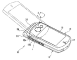
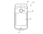
図1は、携帯電子機器を示す斜視図、図2は、携帯電子機器を示す閉状態における正面図、図3は、携帯電子機器を示す開状態における正面図である。
Hereinafter, a portable electronic device according to the best mode for carrying out the present invention will be described with reference to the drawings.
FIG. 1 is a perspective view showing a portable electronic device, FIG. 2 is a front view showing the portable electronic device in a closed state, and FIG. 3 is a front view showing the portable electronic device in an opened state.
図に示すように、この携帯電子機器11は、第1の筐体12及び第2の筐体13を有している。これら第1の筐体12及び第2の筐体13は、一端側近傍の連結部14にて、前記第2の筐体13の第1の筐体12と対向する対向面に直交する軸線Xを中心として面方向に相対的に回動可能に連結され、第1の筐体12と第2の筐体13とが互いに重ね合わされた閉状態(図1における実線で示す状態及び図2の状態)及び第1の筐体12と第2の筐体13とを相対的に回転させて伸長させた開状態(図1における鎖線にて示す状態及び図3の状態)の2つの形態となる、いわゆる回転型のものである。
As shown in the figure, the portable
第1の筐体12には、第2の筐体13と対向する面と反対側の面に、電話機の操作メニューや画像等を表示するための液晶ディスプレイや有機ELディスプレイ等からなる表示装置15及びスピーカ17を有すると共に、側面にサイドキー18cが設けられている。
一方、第2の筐体13には、第1の筐体12と対向する面に、ダイヤル入力やメニュー操作に使用する不図示のテンキー18aやカーソルキー18b及びマイクをそれぞれ有すると共に、側面にサイドキー18dが設けられ、その他に図示しないバッテリ、CPU、メモリ、無線部等の携帯電話を構成する要素が収容されている。
The
On the other hand, the
図4は、携帯電子機器の機能を説明するブロック図である。
図に示すように、この携帯電子機器11は、CPU21を有し、このCPU21には、表示装置15からなる表示部22、テンキー18a、カーソルキー18b、サイドキー18c、18dなどの操作部23、ROMやRAMなどのメモリ24及び無線部25が接続されている。そして、CPU21によって、これら表示部22、操作部23メモリ24及び無線部25による通信処理などが行われる。
FIG. 4 is a block diagram illustrating functions of the portable electronic device.
As shown in the figure, the portable
そして、携帯電子機器11の待ち受け時は、第1の筐体12が第2の筐体13に重なるように配置された閉状態にあり、この状態で携帯電子機器11に搭載されている機能を使用する場合には、各筐体12、13の側面に備えるサイドキー18c、18dを操作することで選択した機能を起動させることができるようになっている。また、通話を行うためのダイヤル入力や文字入力等が必要な時には、前記サイドキー18c、18dによる入力ができないため、第1筐体12を連結部14にて180度回動させてテンキー18aやカーソルキー18bを露出させる開状態(図1中破線で示す状態)とし、テンキー18aやカーソルキー18bを操作して文字入力を行うようになっている。
When the portable
ところで、第1の筐体12と第2の筐体13は、互いの筐体12、13が回動する際に対向面同士が摺動して傷付くことを防止するため、微少隙間Lを設けた状態で連結部14を介して連結されている。
次に、第1の筐体12及び第1の筐体13を回動可能に連結する連結部14について説明する。
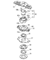
図6及び図7に示すように、連結部14は、第1の筐体12側に設けられた回動軸部52及び第2の筐体13側に設けられた軸受部53から構成されている。
By the way, the
Next, the
As shown in FIGS. 6 and 7, the connecting
回動軸側52は、第1の筐体12に固定される揺動板61と、この揺動板61が固定される揺動ブロック62と、この揺動ブロック62が揺動可能に取り付けられる回動ピン部63とを有している。
軸受部53は、中心に平面形状が円形の摺動孔64を有すると共に、外周にフランジ65を備え、前記摺動孔64の中心軸が軸線Xと一致するように軸受部53を第2の筐体13の所定位置に位置決めした後、軸受け部53のフランジ65を第2の筐体13の壁部とボルト等で締結することで軸受部53が第2の筐体13に固定されている。
The
The
回動軸部52の回動ピン部63は、その下端に摺動ピン部63aを有しており、この摺動ピン部51は、軸受部53の摺動孔64に摺動可能に嵌入されている。そして、この摺動ピン部51には、保持リング66,保持ブラケット67を介して、複数のワッシャ68,69,70が嵌合され、前記摺動ピン部51の端部をかしめることにより、回動ピン部63が軸受け部53に対して軸線Xを中心として回動可能に連結されている。
また、回動ピン部63の外側には揺動ブロック62が遊嵌され、この揺動ブロック62と揺動板61とをネジにて固定することで、前記回動ピン部63の先端より外側に突出する一対のピン63bを、揺動ブロック62に形成された一対の凹部62aと揺動板61とで形成される空間内に回転可能に収容するようになっており、これにより、一体化された揺動ブロック62と揺動板61とを回動ピン部63に対して摺動させることができるように構成されている。
The
Further, a
また、軸受部53の上面には傾斜面53aを有し、回動ピン部63が回動するときには揺動ブロック62に設けられた突起62bが前記傾斜面53a上を移動するようになっており、これにより前記揺動ブロック62と揺動板61が軸線Xに直交する摺動軸Yを中心として所定角度摺動させることができるようになっている。その為、第1の筐体12を閉状態から回動させて開状態とすると、図1の破線で示すように、第1の筐体12を第2の筐体13に対して所定角度傾斜させた状態で保持することができるようになっている。なお、符号72は、揺動ブロック62の突起62bを軸受部53の傾斜面53aに常に付勢するためのバネである。
Further, the upper surface of the
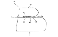
また、第1の筐体12を第2の筐体13に対して傾斜させると、第1の筐体12の一端部側(連結部14側)が第2の筐体13と接触するため、第1の筐体12の対向面と一端面とで形成される角部には、第1の筐体12が所定角度傾斜した際に第2の筐体13の対向面と略平行に対向するテーパー面12aを形成してある。
Further, when the
一方、第1の筐体12及び第2の筐体13には、連結部14の周囲における互いの対向面に、ポリテトラフルオロエチレン(PTFE)、ポリアミド(PA)、ポリアセタール(POM)、ポリカーボネート(PC)、アクロルニトリルブタジエンスチレン(ABC)のいずれか一つからなる摺動性樹脂材からなる当接プレート(第1及び第2の保持部材)42,43がそれぞれ設けられている。
On the other hand, the
第1の筐体12の対向面側に設けられた当接プレート(第1の保持部材)42は、第1の筐体12の一端面側を除く連結部14の周囲に設けられた略半円弧状をしたもので、当接プレート(第1の保持部材)42の両端面はそれぞれテーパ面12aまで延設してある。つまり、この当接プレート(第1の保持部材)42は、第1の筐体12の裏面に配置された部分が平面部42aとされ、テーパ面12aに配置された部分が傾斜面部42bとされている。
第2の筐体13の対向面に設けられた当接プレート(第2の保持部材)43は、その平面形状が長方形をしたもので、連結部14を挟んで両側にそれぞれ配置されている。
各当接プレート42,43は、各筐体12,13の対向面より突出させてあり、少なくとも携帯電子機器11の閉状態においては、第2の筐体13上の当接プレート(第2の保持部材)43と、第1の筐体12上の当接プレート(第1の保持部材)42の平面部42aとが当接し、連結部14を挟んで左側(一方側)に設けられた微少隙間と右側(他方側)に設けられた微少隙間の間隔が略同等となるように構成されている。
その為、設計上あるいは組立上のがたつきより、第1の筐体12が第2の筐体13に対して連結部14を支点として左右に多少の傾きがあったとしても、第1の筐体12と第2の筐体13とは、連結部14を支点として、左右にぐらつくことなく、安定して接触した閉状態が維持される。
The contact plate (first holding member) 42 provided on the facing surface side of the
The contact plate (second holding member) 43 provided on the facing surface of the
The
For this reason, even if the
また、第1の筐体12を第2の筐体13に対して回動させると、第1の筐体12が揺動軸Yを中心として僅かに回動され、第1の筐体12の当接プレート42の平面部42aが第1の筐体12とともに傾くことにより、第2の筐体13の当接プレート43から離れる。
これにより、第1の筐体12を第2の筐体13に対してさらに回動させる際にも、当接プレート42と当接プレート43との接触がなくされる。なお、設計上あるいは組立上のがたつきより、第1の筐体12が第2の筐体13に対して連結部14を支点として傾いたとしても、当接プレート42が一方側の当接プレート43に多少接触して摺動することとなる。つまり、当接プレート42、43同士が大きな接触力によって摺動するようなことはない。
Further, when the
Accordingly, even when the
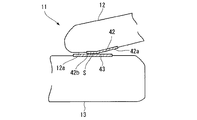
そして、この第1の筐体12を第2の筐体13に対して180°回動させて開状態とすると、図10に示すように、第1の筐体12の当接プレート42の傾斜面部42bが第2の筐体13の当接プレート43に対して略平行にされ、これら当接プレート42の傾斜面部42bと当接プレート43との間に僅かな隙間Sが形成されるようにしてある。
なお、本実施形態では開状態のときに当接プレート42の傾斜面部42bと当接プレート43とを離間させることとしたが、開状態での安定性を高めるために両者を当接させるようにしても構わない。
Then, when the
In this embodiment, the
このように、上記実施形態に係る携帯電子機器11によれば、少なくとも閉状態にて、連結部14の両側部の当接プレート42の平面部42aと当接プレート43とが互いに当接するので、設計上あるいは組立上のがたつきがあったとしても、第1の筐体12及び第2の筐体13が、連結部14を支点として左右に傾くような不具合なく、重ね合わされた閉状態とすることができ、閉状態における見栄えを良くして商品価値を高めることができる。
また、回動時には、当接プレート42、43同士が離間するので、回動時における摺動による摩耗を低減させることができ、長寿命化を図ることができる。
As described above, according to the mobile
Further, since the
さらには、第1の筐体12と第2の筐体13とを回動させることにより、揺動機構71によって第1の筐体12と第2の筐体13とを長手方向に沿って傾けて、当接プレート42、43同士を容易に離間させることができ、回動時における摺動による摩耗を容易に低減させることができる。
しかも、当接プレート42、43が、摺動性に優れた材料、例えば、ポリテトラフルオロエチレン(PTFE)、ポリアミド(PA)、ポリアセタール(POM)、ポリカードネート(PC)、アクリルニトリルブタジエンスチレン(ABC)から形成されているので、回動時に、たとえ当接プレート42、43同士が接触したとしても、円滑な回動への影響を最小限に抑えることができ、また、耐摩耗性を高めることができる。
Further, by rotating the
In addition, the
11 携帯電子機器
12 第1の筐体(筐体)
13 第2の筐体(筐体)
14 連結部
42、43 当接プレート(当接部)
X 軸線
Y 揺動軸
11 portable
13 Second housing (housing)
14
X axis line Y swing axis
Claims (3)
少なくとも前記閉状態において前記連結部を挟んで一方の微少間隔と他方の微少間隔を略一定に保つ保持部材を設け、
前記保持部材は一方の筐体に設けられた第1の保持部材と他方の筐体に設けられた第2の保持部材とを有し、前記両保持部材は少なくとも前記収容状態において当接し、
前記連結部には、前記回転軸に直交する揺動軸を中心として一方の筐体を揺動させると共に、前記一方の筐体を他方の筐体に対して傾斜保持する揺動機構を備え、
前記一方の筐体の一端側角部には、前記一方の筐体が傾斜保持されたときに前記他方の筐体と略平行となるテーパ面を有し、当該テーパ面にも前記第1の保持部材が設けられている
ことを特徴とする携帯電子機器。 One end of each of the two casings is connected by a connecting portion, and the two casings are relatively rotated around a rotation axis provided in the connecting portion, so that the casings are slightly spaced apart from each other. A portable electronic device having a closed state and an extended state that are overlapped with each other,
At least in the closed state, a holding member is provided to keep one minute interval and the other minute interval substantially constant across the connecting portion ,
The holding member has a first holding member provided in one housing and a second holding member provided in the other housing, and the both holding members abut at least in the accommodated state,
The connecting portion includes a swing mechanism that swings one housing around a swing shaft that is orthogonal to the rotation axis, and that tilts and holds the one housing with respect to the other housing;
One corner of the one housing has a tapered surface that is substantially parallel to the other housing when the one housing is held inclined, and the tapered surface also includes the first surface. A portable electronic device comprising a holding member .
Priority Applications (1)
| Application Number | Priority Date | Filing Date | Title |
|---|---|---|---|
| JP2003348892A JP4298461B2 (en) | 2003-10-07 | 2003-10-07 | Portable electronic devices |
Applications Claiming Priority (1)
| Application Number | Priority Date | Filing Date | Title |
|---|---|---|---|
| JP2003348892A JP4298461B2 (en) | 2003-10-07 | 2003-10-07 | Portable electronic devices |
Publications (2)
| Publication Number | Publication Date |
|---|---|
| JP2005114033A JP2005114033A (en) | 2005-04-28 |
| JP4298461B2 true JP4298461B2 (en) | 2009-07-22 |
Family
ID=34540909
Family Applications (1)
| Application Number | Title | Priority Date | Filing Date |
|---|---|---|---|
| JP2003348892A Expired - Fee Related JP4298461B2 (en) | 2003-10-07 | 2003-10-07 | Portable electronic devices |
Country Status (1)
| Country | Link |
|---|---|
| JP (1) | JP4298461B2 (en) |
Families Citing this family (2)
| Publication number | Priority date | Publication date | Assignee | Title |
|---|---|---|---|---|
| JP5246793B2 (en) * | 2009-05-18 | 2013-07-24 | Necカシオモバイルコミュニケーションズ株式会社 | Housing structure and portable device |
| JP4875137B2 (en) | 2009-11-30 | 2012-02-15 | 株式会社東芝 | Electronics |
-
2003
- 2003-10-07 JP JP2003348892A patent/JP4298461B2/en not_active Expired - Fee Related
Also Published As
| Publication number | Publication date |
|---|---|
| JP2005114033A (en) | 2005-04-28 |
Similar Documents
| Publication | Publication Date | Title |
|---|---|---|
| JP5161336B2 (en) | Switchgear | |
| US7865151B2 (en) | Swing hinge device for mobile terminal | |
| EP1693539B1 (en) | Hinge device for a display for rotation type mobile phone | |
| JP5611743B2 (en) | Cover mechanism for switchgear | |
| KR20120008682U (en) | Design and implementation of friction hinge with a range of motion and detent separation greater than 180 degrees | |
| EP1950937A2 (en) | Portable apparatus | |
| US7526082B2 (en) | Portable terminal and opening or closing method therefor | |
| WO2006115144A1 (en) | Hinge mechanism and portable terminal | |
| JP4537930B2 (en) | Horizontal rotation mechanism for portable devices | |
| JP2008035022A (en) | Folding portable communication device | |
| JP4111392B2 (en) | Mobile terminal device | |
| JP4298461B2 (en) | Portable electronic devices | |
| JP4578717B2 (en) | Mobile terminal device | |
| JP2005030542A (en) | Hinge structure and electronic device | |
| EP1511312B1 (en) | Cameralens assembly for portable wireless terminals | |
| GB2417851A (en) | Mobile phone with sliding and rotating hinge | |
| JP2005534237A (en) | Automatic opening mechanism for electronic devices | |
| JP3947484B2 (en) | Mobile terminal device | |
| KR100834611B1 (en) | Key input device for mobile phone | |
| JP2004084929A (en) | Portable terminal unit and its opening-closing method | |
| KR20040046564A (en) | Portable communication apparatus with data inputting expansion | |
| JP2005303926A (en) | Portable telephone set | |
| JP4152342B2 (en) | HINGE DEVICE AND ELECTRONIC DEVICE USING HINGE DEVICE | |
| JP5601101B2 (en) | Mobile terminal device | |
| JP4348218B2 (en) | Biaxial rotating unit and portable terminal device |
Legal Events
| Date | Code | Title | Description |
|---|---|---|---|
| A621 | Written request for application examination |
Free format text: JAPANESE INTERMEDIATE CODE: A621 Effective date: 20060912 |
|
| A977 | Report on retrieval |
Free format text: JAPANESE INTERMEDIATE CODE: A971007 Effective date: 20081208 |
|
| A131 | Notification of reasons for refusal |
Free format text: JAPANESE INTERMEDIATE CODE: A131 Effective date: 20081216 |
|
| A521 | Written amendment |
Free format text: JAPANESE INTERMEDIATE CODE: A523 Effective date: 20090212 |
|
| TRDD | Decision of grant or rejection written | ||
| A01 | Written decision to grant a patent or to grant a registration (utility model) |
Free format text: JAPANESE INTERMEDIATE CODE: A01 Effective date: 20090324 |
|
| A01 | Written decision to grant a patent or to grant a registration (utility model) |
Free format text: JAPANESE INTERMEDIATE CODE: A01 |
|
| A61 | First payment of annual fees (during grant procedure) |
Free format text: JAPANESE INTERMEDIATE CODE: A61 Effective date: 20090415 |
|
| R150 | Certificate of patent or registration of utility model |
Free format text: JAPANESE INTERMEDIATE CODE: R150 |
|
| FPAY | Renewal fee payment (event date is renewal date of database) |
Free format text: PAYMENT UNTIL: 20120424 Year of fee payment: 3 |
|
| FPAY | Renewal fee payment (event date is renewal date of database) |
Free format text: PAYMENT UNTIL: 20120424 Year of fee payment: 3 |
|
| FPAY | Renewal fee payment (event date is renewal date of database) |
Free format text: PAYMENT UNTIL: 20130424 Year of fee payment: 4 |
|
| FPAY | Renewal fee payment (event date is renewal date of database) |
Free format text: PAYMENT UNTIL: 20140424 Year of fee payment: 5 |
|
| LAPS | Cancellation because of no payment of annual fees |