JP4298317B2 - Image reading apparatus and image forming apparatus - Google Patents
Image reading apparatus and image forming apparatus Download PDFInfo
- Publication number
- JP4298317B2 JP4298317B2 JP2003038813A JP2003038813A JP4298317B2 JP 4298317 B2 JP4298317 B2 JP 4298317B2 JP 2003038813 A JP2003038813 A JP 2003038813A JP 2003038813 A JP2003038813 A JP 2003038813A JP 4298317 B2 JP4298317 B2 JP 4298317B2
- Authority
- JP
- Japan
- Prior art keywords
- image
- carriage
- home position
- document
- image reading
- Prior art date
- Legal status (The legal status is an assumption and is not a legal conclusion. Google has not performed a legal analysis and makes no representation as to the accuracy of the status listed.)
- Expired - Fee Related
Links
Images


Description
【0001】
【発明の属する技術分野】
本発明は、キャリッジが移動して原稿台に置かれた原稿を走査することにより画像を読み取る画像読み取り装置およびその画像読み取り装置を備えた画像形成装置に関する。
【0002】
【従来の技術】
複写機、ファクシミリ、スキャナなどの画像形成装置においては、原稿台に置かれた原稿を走査して原稿画像を読み取る画像読み取り装置(スキャナ)が設けられている。この画像読み取り装置には、原稿を照明する光源および原稿からの反射光を所定の方向に導くミラーを支持しながら原稿の所定の方向に沿って(副走査方向)移動するキャリッジが備えられており、原稿を走査する際にはこのキャリッジのスタート位置の精度が極めて重要である。そのため、従来の画像読み取り装置においては、キャリッジの基準位置であるホームポジションの近傍にホームポジションを検出するセンサ(検出手段)を設け、このセンサの検出出力によってホームポジションを検出するようにしている。このホームポジションサーチすなわちホーミング処理(以下、ホーミング処理と称する)は、複写機の場合はコピーボタンの押下の際にコピーのための予備走査を行ったり、ファクシミリやスキャナの場合は原稿の読み取りのための本走査を行う直前に行うように構成されている。このように、電源オン時にキャリッジの位置あわせを行うホーミング動作を実施した後にスキャン開始可能となる制御が行われていたので、ホーミング処理の分だけファーストコピーやファースト読み取り時間が長くなってしまうのが通例であった。
【0003】
一方、近年、省エネ、環境問題の高まりにより、不要な時間はすぐに電源を自動的に落とすような動作が求められてきたが、その反面、電源オン後に素早い立ち上がりも求められてきている。
【0004】
そこで、例えば特許文献1には、キャリッジの復帰動作時に位置ずれが発生した場合のみ、キャリッジの位置ずれ補正やホーミング処理を行わせることで、繰り返しの読み取り動作を迅速にすることが提案されている。また、特許文献2では、ホーミング処理時のセンサの読み取り出力とキャリッジの移動距離とによる黒基準値が、予め設定された上下限値を超えた場合は、前回検出した値が上下限値を超えていなければ、前回検出した値を補正の基準値として用いることにより読み取り画像の位置精度を高め、位置のバラ付きの少ない画像を得ることが提案されている。
【0005】
【特許文献1】
特開2001−356428号公報
【0006】
【特許文献1】
特開2002−64683号公報
【0007】
【発明が解決しようとする課題】
本発明も上述した特許文献記載の発明と同様に、予めプレスキャン開始命令で装置が起動する様な条件の場合には、一定の条件を満たしていれば、正確な位置あわせは必要ないと考えホーミング動作を省略しスキャン開始とすることにより、素早い立ち上がりを得ることを目的としている。
【0008】
【課題を解決するための手段】
前記目的を達成するため、第1の手段は、原稿を照明する光源及び該光源で照明された原稿からの反射光を導くミラーを搭載し、原稿に対して副走査方向に移動可能なキャリッジと、該キャリッジのホームポジションを検出するための検出手段と、前記ミラーからの反射光から前記原稿の主走査方向の画像を読み取るラインセンサと、前記キャリッジの移動を制御する制御手段と、を備えた画像読み取り装置において、前記制御手段は、電源オン時にホーミング処理を行うことによってキャリッジの位置あわせを行う際、プレスキャンを行うモードの場合に、前記検出手段が前記電源オン時に前記キャリッジを検出したときには前記ホーミング処理を行わないことを特徴とする。
【0012】
第2の手段は、第1の手段に係る画像読み取り装置と、前記画像読み取り装置によって読み取った画像データに基づいて記録媒体に可視画像を形成する画像形成手段とを備えていることを特徴とする。
【0013】
第1の手段によれば、予めプレスキャン開始命令で装置が起動するような条件の場合に、一定の条件を満たしていれば、正確な位置あわせは必要ないと考えホーミング動作を省略しスキャン開始とすることになり、素早い立ち上がりを得ることができる。
【0014】
第2の手段によれば、検出手段をキャリッジ移動方向に対してずらして配置したことにより、単一の検出手段の時よりも位置検出を精度良く行うことができ、また、ホーミングの際、最小限のキャリッジの移動によりホームポジションを決定することができる。
【0015】
第3の手段によれば、電源オン起動時にキャリッジがホームポジションにあるかどうかを正確に判断でき、正常な位置にあるときには、ホーミングを省略することにより、起動条件なしに起動時間を短縮することができる。
【0016】
第4の手段によれば、検出手段が、前記キャリッジの移動方向に直交する方向の両端部あるいは装置筐体の前記両端部と相対する側面に設けているので、位置検出が精度良く行える。
【0017】
第5の手段によれば、電源オン後に素早い立ち上がりで画像読み取り装置が動作するので、効率よく作業を行うことができる。
【0018】
【発明の実施の形態】
以下、図面を参照し、本発明の実施形態について説明する。
【0019】
図1は、本発明の第1の実施形態における画像読み取り装置を示す要部構成図、図2は画像読み取り装置が搭載された画像形成装置の上部の一部を示す図、図3はキャリッジとホームポジションセンサの関係を説明するための図、図4はスキャン制御の動作概要を示すフローチャートである。
【0020】
画像読み取り装置50は、その上部にコンタクトガラス6と基準白板(図示しない)が配置されている。コンタクトガラス6は原稿を読み取る際にその上に原稿をセットするためのものである。原稿は図2に示すように、上から原稿の押さえ板である圧板1aによりコンタクトガラス6から浮かないように押さえられる。勿論、公知のドキュメントフィーダ(ADF)を設けてもよい。また、基準白板はシェーディング補正時の補正データを得るための主走査方向に設けられた均一濃度のほぼ白色の部材である。
【0021】
画像読み取り装置50の内部には、基準白板あるいはコンタクトガラス6の面に対してある角度で読み取り面を照射するキセノンランプのような光源504と、基準白板あるいは原稿で反射した光を反射する3枚の第1、第2および第3のミラー52,55,56と、第3のミラー56からの反射光を結像するレンズブロック53と、レンズ6を反射光をアナログ画像信号に変換するラインセンサであるCCD54と、このCCD54からの画像信号をデジタル信号に変換するための各種回路が設けられた読取基板507とから構成されている。光源504と第1ミラー52は第1キャリッジ501に搭載され、第2および第3ミラー55,56は第2キャリッジ502に搭載されている。第1および第2キャリッジ501,502は、駆動モータ505によりそれぞれ2:1の速度でコンタクトガラス6に沿って移動しながら、原稿の画像を読み取っていく。
【0022】
画像読み取り装置50の底部には、原稿のサイズを検出する複数個の原稿サイズ検知センサ514が設けられ、上部には圧板1aの開閉を検出する圧板開放検知センサ515、第1キャリッジ501のホームポジションを検出するホームポジションセンサ506が設けられている。この外に、図示していないが、駆動モータ503の周辺回路が設けられ、それぞれの検出タイミングで読み取り制御が行われている。
【0023】
第1キャリッジ501がホームポジションに位置したか否かの検出は、第1キャリッジ501に設けられたフィラー509がホームポジションセンサ506内に入るとセンサ506がオンし、センサ506から外れるとオフとなるのを利用している。
【0024】
従来は、画像読み取り装置50の電源を入れると、第1キャリッジ501がホーミング動作を行い、その後、読取基板507の黒レベル,白レベル調整等の調整を行った後に画像読み取り装置50は、読み取り動作可能の状態になる制御が行われていた。
【0025】
ここでホーミング動作は、電源オン時にホームポジションセンサ506がオンしているときは、ホームポジションセンサ506から離れる方向へ一旦第1キャリッジ501を動かし、ホームポジションセンサ506がオフした後に再度オンする方向へ戻してオンするタイミングを確定して位置精度を向上させホームポジションとしている。また、電源オン時にホームポジションセンサ506がオフしているときには、オンする方向へ第1キャリッジ501を動かし同様にホームポジションを決定している。
【0026】
近年、省エネ技術が進む中で、読み取り動作を行っていないときは、不必要な電力の消費を押さえるために画像読み取り装置の電源を遮断するという方式が一般化してきている。この場合、ユーザーが使用したいときに、ホーミング処理や読取基板507の調整といった初期動作を毎回待たないとスキャン動作を行うことができないため、待たされることが多くなるという課題が顕在化してきた。従来は、電源を入れっぱなしにしておけば、そのような初期動作は不要ですぐにスキャンできたことから、省エネの効果は上がるが、ストレスも増大することになってきた。
【0027】
そこで、この第1の実施形態においては、プレスキャンを要求されることによって、省エネモード(電源オフ)から自動復帰するような場合に限って、ある条件を満たしていれば、ホーミング動作を省略することにより復帰時間を短縮するようにしている。
【0028】
一般的なスキャナにおいて、プレスキャンという限定された条件をトリガにして省エネモードから復帰する場合としては、ネットワークスキャナ等が考えられる。すなわち、ネットワーク上から画像読み取り装置に対して、これからプレスキャンを行うといったコマンドを送出しておき、それから原稿をセットするような場合である。プレスキャンというのは、事前に各種の設定が正しいかどうか試してみたりする目的に使用されることが多く、そのため、もしユーザーが気に入らない読み取りデータであったら、そのデータは破棄されるのが通常である。従って、若干のレジストズレがあっても原稿のイメージが確認できれば良くレジスト精度が問題となる可能性は低いと考えられる。
【0029】
そこで、第1の実施形態においては、図4のフローチャートに示すように、スキャンコマンドを受信したとき、先ずそのコマンドがプレスキャンコマンドであるか否かをチェックする(ステップ101)。コマンドがプレスキャンコマンドでない場合はホーミングを実施し(ステップ102)、その後光源4のランプを点灯する。
【0030】
一方、コマンドがプレスキャンコマンドであるときに、ホームポジションセンサ506の状態がオンであれば、少なくともホームポジション近辺に第1キャリッジ501は存在するということがいえるため、ホーミングを省略して復帰させても問題が生じにくい。したがって、ホーミングを省略してステップ103に進ませる。逆にホームポジションセンサ506がオフしている状態であれば、第1キャリッジ501は、かなりホームポジションから離れているものと考えられ、そのまま読み取り開始をしてしまうと第1キャリッジ501が、画像読み取り装置の端にぶつかって破損してしまう可能性が考えられるため、ホーミングは必須であるので、ステップ102に進みホーミングを実施した後、ステップ103に進む。
【0031】
ランプ点灯後は、読取基板507の黒レベル,白レベル調整等の調整を行い(ステップ104)、その後に画像読み取り装置50は、読み取り動作可能な状態になり(ステップ105)、スキャナ動作が開始される(ステップ106)。
【0032】
これらの制御を行うことにより、復帰時間を短縮させることが可能である。また、従来機に対してソフトウェアの変更で容易に対処が可能であり、ハードウェアの変更は必要ないため新規に開発する機種でなくても反映可能な点にメリットがある。
【0033】
上述した第1の実施形態では、ホームポジションセンサは1つであったが、次に説明する第2の実施形態においては、2つのホームポジションセンサを用いている。この第2の実施形態を図5および図6により説明する。図5は第2の実施形態におけるキャリッジとホームポジションセンサとの位置関係を説明する図、図6は第2の実施形態におけるスキャン制御の動作概要を示すフローチャートである。なお、ここでは第2の実施形態として説明しているが、この第2の実施形態は、本発明における他のセンサ種類とそのセンサを使用した制御の参考例である。
【0034】
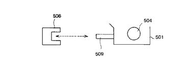
すなわち、図5に示すように、第1キャリッジ501の移動方向に直交する方向の両端側に、移動方向に対してわずかにずらして第1および第2ホームポジションセンサ521,522を配置している。これにより、検出精度の向上とホーミング時の第1キャリッジ501の移動距離を短縮して復帰時間をも短縮させている。
【0035】
上述したように、第1の実施形態では、ホームポジションセンサ506に対して第1キャリッジ501がオフオンすることにより位置を確定しているが、第1キャリッジ501の両端に第1ホームポジションセンサ521と第2ホームポジションセンサ522を配し、さらにその取り付け位置を移動方向に直交する方向に若干ずらすことにより、第1ホームポジションセンサ521はオン、第2ホームポジションセンサ522はオフといった状態を作り出すことができる。このホームポジションセンサのずらし量を小さくしていくと、お互いにオフオンしている状態がピンポイントとなり位置精度は向上していく。従って、この第2の実施形態によれば、第1の実施形態よりも正確なホームポジションを得ることが可能になる。
【0036】
また、ホーミング処理の際、第1の実施形態ではホームポジションセンサ506をオフオンさせるために第1キャリッジ501を移動させていたが、第2の実施形態ではわずかなピンポイントの状態検出のみで良くなるため、ホームポジションセンサをオフオンさせて、位置を探る必要がなくなる。その結果、省エネモードよりの復帰のためのホーミングは行うものの、第1キャリッジ501の移動時間が短縮できるため復帰時間の短縮が可能となる。さらに、第1の実施形態のような、限定条件下での復帰ではなく、あらゆる復帰状態に適用可能である。
【0037】
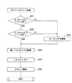
この第2の実施形態においては、図6のフローチャートに示すように、電源遮断をともなう省エネモードからの復帰時にスキャンコマンドを受信したときは、ホームポジションセンサの状態を検出して、第1ホームポジションセンサ521がオンしているか否かをチェックし(ステップ201)、次に第2ホームポジションセンサ522がオンしているか否かをチェックする(ステップ202)。第1ホームポジションセンサ521がオフの場合および第2ホームポジションセンサ522がオフの場合は、ホーミングを実施する(ステップ203)。一方、第1ホームポジションセンサ521がオンで、第2ホームポジションセンサ522もオンの場合、およびステップ203でホーミング処理を実施した後は、光源504のランプを点灯し、読取基板507の黒レベル,白レベル調整等の調整を行い(ステップ204)、その後に画像読取装置50は、読み取り動作可能の状態になり(ステップ205)、スキャナ動作が開始される(ステップ206)。
【0038】
従来機においては、省エネモードに移行するときには、キャリッジがホームポジションに正常に位置していたとしても電源遮断中は、スキャナモータの励磁も不可能であり、外部からの振動や衝撃によりキャリッジが動いてしまっている可能性があるため、復帰時にホーミングを行っていた。これに対し、第2の実施形態においては、電源遮断をともなう省エネモードからの復帰時に、第1および第2ホームポジションセンサ521,522の状態を検出して、第1ホームポジションセンサ521がオン、第2ホームポジションセンサ522がオフの状態(ピンポイント)であれば、第1キャリッジ501がホームポジションにあるものと判断して、ホーミング動作を省略して読み取り可能状態に素早く達することができる。このように、ホームポジションセンサを複数配置することにより、位置の検出精度を向上させることができるので、ホームポジションセンサの状態を確認するだけでホーミングを行う必要があるかどうか容易に判断し、必要のない場合には、ホーミングを行わないことにより復帰時間の短縮が期待できる。
【0039】
以下、第1及び第2の実施形態に係る画像読み取り装置が使用される画像形成装置について説明する。
【0040】
図7は図1に示す画像読み取り装置を備えた画像形成装置の概略構成を示す図、図8は図7に示した画像形成装置の制御回路の概略構成を示すブロック図である。
【0041】
以下、本実施形態に係る画像形成装置について説明する。
自動原稿送り装置(以後ADF)1にある原稿台2に原稿の画像面を上にして置かれた原稿束は、操作部30上のスタートキーが押下されると、一番下の原稿から給送ローラ3、給送ベルト4によってコンタクトガラス6上の所定の位置に給送される。読み取りユニット50によってコンタクトガラス6上の原稿の画像データを読み取り後、読み取りが終了した原稿は、給送ベルト4及び排送ローラ5によって排出される。さらに、原稿セット検知センサ7によって原稿台2に次の原稿があることを検知した場合、前原稿と同様にコンタクトガラス6上に給送される。給送ローラ3、給送ベルト4、排送ローラ5は搬送モータ26によって駆動される。
【0042】
第1トレイ8、第2トレイ9、第3トレイ10に積載された転写紙は、各々第1給紙装置11、第2給紙装置12、第3給紙装置13によって給紙され、縦搬送ユニット14によって感光体15に当接する位置まで搬送される。読み取りユニット50によって読み込まれた画像データは、書き込みユニット57からのレーザによって感光体15に書き込まれ、現像ユニット27を通過することによってトナー像が形成される。そして、転写紙は感光体15の回転と等速で搬送ベルト16によって搬送されながら、感光体15上のトナー像が転写される。その後、定着ユニット17にて画像を定着させ、排紙ユニット18によって後処理装置のフィニシャ60に排出される。
【0043】
後処理装置のフィニシャ60は、本体の排紙ローラ19によって搬送された転写紙を、通常排紙ローラ62方向と、ステープル処理部方向へに導くことができる。切り替え板61を上に切り替えると、搬送ローラ63を経由して通常排紙トレイ64側に排紙し、切り替え板61を下方向に切り替えると、搬送ローラ65,67を経由して、ステープル台68に搬送することができる。
【0044】
ステープル台68に積載された転写紙は、一枚排紙されるごとに紙揃え用のジョガー69によって、紙端面が揃えられ、一部のコピー完了と共にステープラ66によって綴じられる。ステープラ66で綴じられた転写紙群は自重によって、ステープル完了排紙トレイ70に収納される。
【0045】
一方、通常の排紙トレイ64は前後に移動可能な排紙トレイである。前後に移動可能な排紙トレイ部64は、原稿毎、あるいは、画像メモリによってソーティングされたコピー部毎に、前後に移動し、簡易的に排出されてくるコピー紙を仕分ける機能を有する。
【0046】
転写紙の両面に画像を作像する場合は、各給紙トレイ8〜10から給紙され作像された転写紙を排紙トレイ64側に導かないで、経路切り替えの為の分岐爪41を上側にセットすることにより、一旦両面給紙ユニット111にストックする。その後、両面給紙ユニット111にストックされた転写紙は再び感光体15に作像されたトナー画像を転写するために、両面給紙ユニット111から再給紙され、経路切り替えの為の分岐爪41を下側にセットし、排紙トレイ64に導く。この様に転写紙の両面に画像を作成する場合に両面給紙ユニット111は使用される。
【0047】
感光体15、搬送ベルト16、定着ユニット17、排紙ユニット18、現像ユニット27はメインモータ25によって駆動され、各給紙装置11〜13はメインモータ25の駆動を各々給紙クラッチ22〜24によって伝達駆動される。縦搬送ユニット14はメインモータ25の駆動を中間クラッチ21によって伝達駆動される。
【0048】
図8はメインコントローラを中心に、制御装置を図示したものである。メインコントローラ20は画像形成装置全体を制御する。メインコントローラ20には、紙搬送等に必要なメインモータ25、各種クラッチ21〜24が接続されている。また、オペレータに対する表示、オペレータからの機能設定入力制御を行う操作部30、スキャナの制御、原稿画像を画像メモリに書き込む制御、画像メモリからの作像を行う制御等を行う画像処理ユニット(IPU)49、原稿自動送り装置(ADF)1、等の分散制御装置が接続されている。前記表示は液晶ディスプレイ31を介して行われ、オペレータからの機能設定入力はキー入力手段32によって行われる。各分散制御装置とメインコントローラ20は必要に応じて機械の状態、動作司令のやりとりを行っている。各分散制御装置が実行する制御プログラムは各分散制御装置内部のROMに格納されている。メインコントローラ20にはICカードスロット27が接続されており、ICカードスロット27を介して、画像形成装置外部のICカードに格納されている制御プログラムデータを分散制御装置内部のROMにダウンロードし、制御プログラムを変更することが可能である。
【0049】
再び図7を用いて画像形成装置における画像読み取りから画像の書き込みまでの動作を説明する。
【0050】
読み取りユニット50は、原稿を載置するコンタクトガラス6と光学走査系で構成されており、光学走査系には、露光ランプ51、第1ミラー52、レンズ53、CCDイメージセンサ514等々で構成されている。露光ランプ51及び第1ミラー52は図示しない第1キャリッジ上に固定され、第2ミラー55及び第3ミラー56は図示しない第2キャリッジ上に固定されている。原稿像を読み取るときには、光路長が変わらないように、第1キャリッジと第2キャリッジとが2対1の相対速度で前述のように機械的に走査される。
【0051】
この光学走査系は、図示しないスキャナ駆動モータにて駆動される。原稿画像は、CCDイメージセンサ54によって読み取られ、電気信号に変換されて処理される。レンズ53及びCCDイメージセンサ54を図7において左右方向に移動させることにより、画像倍率が変わる。すなわち、指定された倍率に対応してレンズ53及びCCDイメージセンサ54の左右方向に位置が設定される。
【0052】
書き込みユニット57はレーザ出力ユニット58、結像レンズ59、ミラーで構成され、レーザ出力ユニット58の内部には、レーザ光源であるレーザダイオード及びモータによって高速で定速回転する回転多面鏡(ポリゴンミラー)が備わっている。
【0053】
レーザ出力ユニット58より照射されるレーザ光は、定速回転するポリゴンミラーで偏向され、結像レンズ59を通り、ミラーで折り返され、感光体15面上に集光結像する。
【0054】
偏光されたレーザ光は感光体15が回転する方向と直行する方向(主走査方向)に露光走査され、後述する画像処理部のセレクタより出力された画像信号のライン単位の記録を行う。感光体15の回転速度と記録密度に対応した所定の周期で主走査を繰り返すことによって、感光体面上に画像(静電潜像)が形成される。
【0055】
上述のように、書き込みユニット58から出力されるレーザ光が、画像作像系の感光体15に照射される。図示しないが感光体15の一端近傍のレーザビームを照射される位置に、主走査同期信号を発生するビームセンサが配置されている。
【0056】
なお、図7に示した画像形成装置はMFP複写機として機能する。
【0057】
【発明の効果】
以上のように、本発明に係る画像読み取り装置によれば、例えば、ネットワークからの起動しプレスキャンを行う場合に、従来行っていたホーミング処理を省略することができ、起動時間を短縮することによって、省エネ時に要求される未使用時の電源遮断においてユーザーの使用時のストレスを従来機に対する簡易な制御変更により、軽減させることができる。
【0058】
また、本発明の画像形成装置によれば、電源オン後に素早い立ち上がりで画像読み取り装置が動作するので、効率よく作業を行うことができる。
【図面の簡単な説明】
【図1】本発明の第1の実施形態における画像読み取り装置を示す要部構成図である。
【図2】図1の画像読み取り装置が搭載される画像形成装置の上部の一部を示す図である。
【図3】キャリッジとホームポジションセンサの関係を説明するための図である。
【図4】第1の実施形態におけるスキャン制御の動作概要を示すフローチャートである。
【図5】本発明の第2の実施形態におけるキャリッジとホームポジションセンサとの位置関係を説明する図である。
【図6】第2の実施形態におけるスキャン制御の動作概要を示すフローチャートである。
【図7】第1及び第2の実施形態に係る画像読み取り装置を備えた画像形成装置の概略構成を示す図である。
【図8】図7に示した画像形成装置の制御装置の概略を示すブロック図である。
【符号の説明】
2 コンタクトガラス
3 圧板
4 光源
5a,5b,5c 第1、第2および第3のミラー
6 レンズブロック
7 読取基板
7a CCD
50 画像読み取り装置
501 第1キャリッジ
502 第2キャリッジ
506,521,522 ホームポジションセンサ[0001]
BACKGROUND OF THE INVENTION
The present invention relates to an image reading apparatus that reads an image by scanning a document placed on a document table by moving a carriage, and an image forming apparatus including the image reading apparatus.
[0002]
[Prior art]
2. Description of the Related Art Image forming apparatuses such as copying machines, facsimile machines, and scanners are provided with an image reading device (scanner) that scans a document placed on a document table and reads a document image. The image reading apparatus includes a light source that illuminates a document and a carriage that moves along a predetermined direction (sub-scanning direction) of the document while supporting a mirror that guides reflected light from the document in a predetermined direction. When scanning a document, the accuracy of the carriage start position is extremely important. Therefore, in the conventional image reading apparatus, a sensor (detection means) for detecting the home position is provided in the vicinity of the home position which is the reference position of the carriage, and the home position is detected by the detection output of this sensor.OutLike to do. This home position search, that is, homing processing (hereinafter referred to as homing processing) is to perform preliminary scanning for copying when the copy button is pressed in the case of a copying machine, or to read an original in the case of a facsimile or scanner. The main scanning is performed immediately before the main scanning. As described above, since the homing operation for positioning the carriage when the power is turned on is controlled so that the scan can be started, the first copy and the first reading time are increased by the homing process. It was customary.
[0003]
On the other hand, in recent years, due to increasing energy saving and environmental problems, there has been a demand for an operation that automatically turns off the power immediately when unnecessary, but on the other hand, a quick start-up after power-on is also required.
[0004]
Therefore, for example,
[0005]
[Patent Document 1]
JP 2001-356428 A
[0006]
[Patent Document 1]
JP 2002-64683 A
[0007]
[Problems to be solved by the invention]
As in the invention described in the above-mentioned patent document, the present invention also considers that accurate positioning is not necessary if a certain condition is satisfied when the apparatus is activated in advance by a pre-scan start command. The purpose is to obtain a quick rise by omitting the homing operation and starting scanning.
[0008]
[Means for Solving the Problems]
To achieve the object, the first means includes a light source for illuminating the document and a mirror for guiding reflected light from the document illuminated by the light source, and a carriage movable in the sub-scanning direction with respect to the document. Detecting means for detecting a home position of the carriage; a line sensor for reading an image of the original in the main scanning direction from reflected light from the mirror; and control means for controlling movement of the carriage. In the image reading apparatus, the control means includesWhen the power is turned onWhen the carriage is aligned by performing the homing process, the detection means is in the pre-scan mode.When the power is turned onWhen the carriage is detected, the homingprocessingIt is characterized by not performing.
[0012]
First2Means1'sAnd an image forming unit that forms a visible image on a recording medium based on image data read by the image reading device.
[0013]
According to the first means, in the case where the apparatus is activated in advance by a pre-scan start command, if a certain condition is satisfied, it is considered that accurate positioning is not necessary, and the homing operation is omitted and the scan starts. Therefore, a quick rise can be obtained.
[0014]
According to the second means, the detection means is arranged so as to be shifted with respect to the carriage movement direction, so that the position detection can be performed with higher accuracy than in the case of a single detection means. The home position can be determined by a limited carriage movement.
[0015]
According to the third means, it is possible to accurately determine whether or not the carriage is in the home position when the power is turned on, and when it is in the normal position, the homing is omitted to shorten the activation time without the activation condition. Can do.
[0016]
According to the fourth means, since the detection means is provided on both end portions in the direction orthogonal to the moving direction of the carriage or on the side surfaces facing the both end portions of the apparatus housing, position detection can be performed with high accuracy.
[0017]
According to the fifth means, since the image reading apparatus operates at a quick rise after the power is turned on, the work can be performed efficiently.
[0018]
DETAILED DESCRIPTION OF THE INVENTION
Hereinafter, embodiments of the present invention will be described with reference to the drawings.
[0019]
FIG. 1 is a main part configuration diagram illustrating an image reading apparatus according to a first embodiment of the present invention, FIG. 2 is a diagram illustrating a part of an upper part of an image forming apparatus on which the image reading apparatus is mounted, and FIG. FIG. 4 is a flowchart for explaining the outline of the operation of scan control.
[0020]
The
[0021]
Inside the
[0022]
A plurality of document
[0023]
Whether or not the
[0024]
Conventionally, when the
[0025]
Here, in the homing operation, when the
[0026]
In recent years, with the progress of energy-saving technology, when the reading operation is not performed, a method of shutting off the power source of the image reading apparatus is generally used in order to suppress unnecessary power consumption. In this case, when the user wants to use the scanner, the scanning operation cannot be performed unless the initial operation such as the homing process or the adjustment of the
[0027]
Therefore, in this first embodiment, the homing operation is omitted if a certain condition is satisfied only when the pre-scan is requested to automatically return from the energy saving mode (power off). Thus, the recovery time is shortened.
[0028]
In a general scanner, a network scanner or the like can be considered as a case of returning from the energy saving mode by using a limited condition of pre-scan as a trigger. That is, this is a case where a command to perform pre-scanning is sent from the network to the image reading apparatus, and then a document is set. Pre-scanning is often used for the purpose of testing whether various settings are correct in advance, so if read data that the user does not like is read, that data is discarded. It is normal. Accordingly, it is considered that registration accuracy is not a problem as long as the image of the document can be confirmed even if there is a slight registration error.
[0029]
Therefore, in the first embodiment, as shown in the flowchart of FIG. 4, when a scan command is received, it is first checked whether or not the command is a pre-scan command (step 101). If the command is not a pre-scan command, homing is performed (step 102), and then the lamp of the light source 4 is turned on.
[0030]
On the other hand, if the command is a pre-scan command and the
[0031]
After the lamp is lit, adjustments such as black level and white level adjustment of the
[0032]
By performing these controls, the recovery time can be shortened. In addition, it is possible to easily cope with the conventional machine by changing the software, and there is an advantage that it can be reflected even if it is not a newly developed model because there is no need to change the hardware.
[0033]
In the first embodiment described above, there is one home position sensor. However, in the second embodiment described below, two home position sensors are used. This second embodiment will be described with reference to FIGS. FIG. 5 is a diagram for explaining the positional relationship between the carriage and the home position sensor in the second embodiment, and FIG. 6 is a flowchart showing an outline of the scan control operation in the second embodiment.In addition, although demonstrated as 2nd Embodiment here, this 2nd Embodiment is a reference example of the control using the other sensor types and the sensor in this invention.
[0034]
That is, as shown in FIG. 5, the first and second
[0035]
As described above, in the first embodiment, the position is fixed by turning the
[0036]
In the homing process, the
[0037]
In the second embodiment, as shown in the flowchart of FIG. 6, when a scan command is received at the time of return from the energy-saving mode with power shutdown, the state of the home position sensor is detected and the first home position is detected. It is checked whether or not the
[0038]
In conventional machines, when shifting to the energy-saving mode, even if the carriage is normally positioned at the home position, the scanner motor cannot be excited while the power is cut off, and the carriage moves due to external vibration or impact. He was homing at the time of return. On the other hand, in the second embodiment, the state of the first and second
[0039]
Hereinafter, an image forming apparatus using the image reading apparatus according to the first and second embodiments will be described.
[0040]
7 is a diagram showing a schematic configuration of an image forming apparatus provided with the image reading apparatus shown in FIG. 1, and FIG. 8 is a block diagram showing a schematic configuration of a control circuit of the image forming apparatus shown in FIG.
[0041]
Hereinafter, the image forming apparatus according to the present embodiment will be described.
When a start key on the
[0042]
The transfer papers stacked on the
[0043]
The
[0044]
The transfer paper loaded on the staple table 68 is aligned by the
[0045]
On the other hand, the normal
[0046]
When forming an image on both sides of the transfer paper, the transfer paper fed from each of the
[0047]
The
[0048]
FIG. 8 illustrates the control device with the main controller as the center. The
[0049]
With reference to FIG. 7 again, the operation from image reading to image writing in the image forming apparatus will be described.
[0050]
The
[0051]
This optical scanning system is driven by a scanner drive motor (not shown). The document image is read by the
[0052]
The
[0053]
Laser light emitted from the
[0054]
The polarized laser light is exposed and scanned in the direction (main scanning direction) perpendicular to the direction in which the
[0055]
As described above, the laser beam output from the
[0056]
The image forming apparatus shown in FIG. 7 functions as an MFP copier.
[0057]
【The invention's effect】
As described above, according to the image reading apparatus according to the present invention, for example, when starting from a network and performing a pre-scan, the homing process that has been conventionally performed can be omitted, and the startup time can be shortened. In addition, when the power is shut down when not in use, which is required when saving energy, the user's stress during use can be reduced by a simple control change over the conventional machine.
[0058]
In addition, according to the image forming apparatus of the present invention, the image reading apparatus operates with a quick rise after the power is turned on, so that the work can be performed efficiently.
[Brief description of the drawings]
FIG. 1 is a main part configuration diagram illustrating an image reading apparatus according to a first embodiment of the present invention.
2 is a diagram showing a part of an upper part of an image forming apparatus on which the image reading apparatus of FIG. 1 is mounted. FIG.
FIG. 3 is a diagram for explaining a relationship between a carriage and a home position sensor.
FIG. 4 is a flowchart showing an outline of scan control operation in the first embodiment;
FIG. 5 is a diagram illustrating a positional relationship between a carriage and a home position sensor according to a second embodiment of the present invention.
FIG. 6 is a flowchart showing an outline of operation of scan control in the second embodiment.
FIG. 7 is a diagram illustrating a schematic configuration of an image forming apparatus including an image reading apparatus according to the first and second embodiments.
8 is a block diagram showing an outline of a control device of the image forming apparatus shown in FIG.
[Explanation of symbols]
2 Contact glass
3 pressure plate
4 Light source
5a, 5b, 5c first, second and third mirrors
6 Lens block
7 Reading board
7a CCD
50 Image reading device
501 First carriage
502 Second carriage
506, 521, 522 Home position sensor
Claims (2)
該キャリッジのホームポジションを検出するための検出手段と、
前記ミラーからの反射光から前記原稿の主走査方向の画像を読み取るラインセンサと、
前記キャリッジの移動を制御する制御手段と、
を備えた画像読み取り装置において、
前記制御手段は、電源オン時にホーミング処理を行うことによってキャリッジの位置あわせを行う際、プレスキャンを行うモードの場合に、前記検出手段が前記電源オン時に前記キャリッジを検出したときには前記ホーミング処理を行わないこと
を特徴とする画像読み取り装置。A light source that illuminates the document and a mirror that guides reflected light from the document illuminated by the light source, and a carriage that is movable in the sub-scanning direction with respect to the document;
Detecting means for detecting the home position of the carriage;
A line sensor that reads an image of the original in the main scanning direction from the reflected light from the mirror;
Control means for controlling movement of the carriage;
In an image reading apparatus comprising:
Wherein, when performing the positioning of the carriage by performing homing upon power-on, when the mode for prescan, perform the homing process when said detecting means detects the carriage when the power is turned on An image reading apparatus characterized by not having any.
前記画像読み取り装置によって読み取った画像データに基づいて記録媒体に可視画像を形成する画像形成手段と、
を備えていることを特徴とする画像形成装置。 An image reading device according to claim 1;
Image forming means for forming a visible image on a recording medium based on image data read by the image reading device;
An image forming apparatus comprising:
Priority Applications (1)
| Application Number | Priority Date | Filing Date | Title |
|---|---|---|---|
| JP2003038813A JP4298317B2 (en) | 2003-02-17 | 2003-02-17 | Image reading apparatus and image forming apparatus |
Applications Claiming Priority (1)
| Application Number | Priority Date | Filing Date | Title |
|---|---|---|---|
| JP2003038813A JP4298317B2 (en) | 2003-02-17 | 2003-02-17 | Image reading apparatus and image forming apparatus |
Publications (3)
| Publication Number | Publication Date |
|---|---|
| JP2004246298A JP2004246298A (en) | 2004-09-02 |
| JP2004246298A5 JP2004246298A5 (en) | 2005-10-27 |
| JP4298317B2 true JP4298317B2 (en) | 2009-07-15 |
Family
ID=33023228
Family Applications (1)
| Application Number | Title | Priority Date | Filing Date |
|---|---|---|---|
| JP2003038813A Expired - Fee Related JP4298317B2 (en) | 2003-02-17 | 2003-02-17 | Image reading apparatus and image forming apparatus |
Country Status (1)
| Country | Link |
|---|---|
| JP (1) | JP4298317B2 (en) |
Families Citing this family (6)
| Publication number | Priority date | Publication date | Assignee | Title |
|---|---|---|---|---|
| JP2006222709A (en) * | 2005-02-10 | 2006-08-24 | Ricoh Co Ltd | Image reader |
| JP2007142759A (en) | 2005-11-17 | 2007-06-07 | Ricoh Co Ltd | Image reading apparatus, image forming apparatus, image reading method, and image reading program |
| JP2007267031A (en) * | 2006-03-28 | 2007-10-11 | Ricoh Co Ltd | Image forming apparatus |
| JP4890393B2 (en) * | 2007-08-28 | 2012-03-07 | 株式会社リコー | Paper processing apparatus and image forming apparatus |
| DE112013007076B4 (en) * | 2013-05-16 | 2019-11-28 | Mitsubishi Electric Corp. | winder |
| JP6379532B2 (en) | 2014-03-10 | 2018-08-29 | 株式会社リコー | Document reading apparatus and image forming apparatus having the same |
-
2003
- 2003-02-17 JP JP2003038813A patent/JP4298317B2/en not_active Expired - Fee Related
Also Published As
| Publication number | Publication date |
|---|---|
| JP2004246298A (en) | 2004-09-02 |
Similar Documents
| Publication | Publication Date | Title |
|---|---|---|
| JP2012054758A (en) | Image reading device and image forming device | |
| JP5760684B2 (en) | Image reading apparatus and image forming apparatus | |
| US20130083367A1 (en) | Sheet-Conveying Device Having Opening | |
| JP2009231887A (en) | Document reader | |
| JP5747662B2 (en) | Image reading apparatus and image forming apparatus | |
| US6226471B1 (en) | Image forming apparatus | |
| JP3598646B2 (en) | Image reading device | |
| JP4298317B2 (en) | Image reading apparatus and image forming apparatus | |
| JP2001005119A (en) | Image reader | |
| JP3132381B2 (en) | Document reading apparatus and document reading method | |
| JP3668601B2 (en) | Image forming apparatus | |
| CN109218557B (en) | Image reading apparatus and image forming apparatus including the same | |
| JP2009118377A (en) | Image reading device and image forming apparatus equipped with it | |
| JP2006331161A (en) | Image forming apparatus and preview display control method | |
| JP4058228B2 (en) | Image forming apparatus | |
| JP4988679B2 (en) | Image reading apparatus and image forming apparatus | |
| JP2006010718A (en) | Image reader and image forming apparatus | |
| JP4602837B2 (en) | Image forming apparatus and preview display control method | |
| JP2006295436A (en) | Image reading apparatus and reading size detecting method | |
| JPH08171266A (en) | Image forming device | |
| JP2016119571A (en) | Image reading device | |
| JP2008060867A (en) | Document reader | |
| JP2023093950A (en) | Image forming apparatus, control method, and program | |
| JP2003204422A (en) | Image reader and image forming apparatus | |
| JP2005075547A (en) | Image forming device |
Legal Events
| Date | Code | Title | Description |
|---|---|---|---|
| A521 | Written amendment |
Free format text: JAPANESE INTERMEDIATE CODE: A523 Effective date: 20050714 |
|
| A621 | Written request for application examination |
Free format text: JAPANESE INTERMEDIATE CODE: A621 Effective date: 20050714 |
|
| A977 | Report on retrieval |
Free format text: JAPANESE INTERMEDIATE CODE: A971007 Effective date: 20080509 |
|
| A131 | Notification of reasons for refusal |
Free format text: JAPANESE INTERMEDIATE CODE: A131 Effective date: 20080805 |
|
| A521 | Written amendment |
Free format text: JAPANESE INTERMEDIATE CODE: A523 Effective date: 20081006 |
|
| TRDD | Decision of grant or rejection written | ||
| A01 | Written decision to grant a patent or to grant a registration (utility model) |
Free format text: JAPANESE INTERMEDIATE CODE: A01 Effective date: 20090331 |
|
| A01 | Written decision to grant a patent or to grant a registration (utility model) |
Free format text: JAPANESE INTERMEDIATE CODE: A01 |
|
| A61 | First payment of annual fees (during grant procedure) |
Free format text: JAPANESE INTERMEDIATE CODE: A61 Effective date: 20090415 |
|
| FPAY | Renewal fee payment (event date is renewal date of database) |
Free format text: PAYMENT UNTIL: 20120424 Year of fee payment: 3 |
|
| FPAY | Renewal fee payment (event date is renewal date of database) |
Free format text: PAYMENT UNTIL: 20130424 Year of fee payment: 4 |
|
| FPAY | Renewal fee payment (event date is renewal date of database) |
Free format text: PAYMENT UNTIL: 20140424 Year of fee payment: 5 |
|
| LAPS | Cancellation because of no payment of annual fees |