JP4298208B2 - Still image pickup device - Google Patents
Still image pickup device Download PDFInfo
- Publication number
- JP4298208B2 JP4298208B2 JP2002050653A JP2002050653A JP4298208B2 JP 4298208 B2 JP4298208 B2 JP 4298208B2 JP 2002050653 A JP2002050653 A JP 2002050653A JP 2002050653 A JP2002050653 A JP 2002050653A JP 4298208 B2 JP4298208 B2 JP 4298208B2
- Authority
- JP
- Japan
- Prior art keywords
- shutter
- light emission
- time
- image sensor
- shutter curtain
- Prior art date
- Legal status (The legal status is an assumption and is not a legal conclusion. Google has not performed a legal analysis and makes no representation as to the accuracy of the status listed.)
- Expired - Fee Related
Links
Images


Classifications
-
- H—ELECTRICITY
- H04—ELECTRIC COMMUNICATION TECHNIQUE
- H04N—PICTORIAL COMMUNICATION, e.g. TELEVISION
- H04N23/00—Cameras or camera modules comprising electronic image sensors; Control thereof
- H04N23/60—Control of cameras or camera modules
- H04N23/667—Camera operation mode switching, e.g. between still and video, sport and normal or high- and low-resolution modes
-
- H—ELECTRICITY
- H04—ELECTRIC COMMUNICATION TECHNIQUE
- H04N—PICTORIAL COMMUNICATION, e.g. TELEVISION
- H04N23/00—Cameras or camera modules comprising electronic image sensors; Control thereof
- H04N23/70—Circuitry for compensating brightness variation in the scene
- H04N23/73—Circuitry for compensating brightness variation in the scene by influencing the exposure time
-
- H—ELECTRICITY
- H04—ELECTRIC COMMUNICATION TECHNIQUE
- H04N—PICTORIAL COMMUNICATION, e.g. TELEVISION
- H04N23/00—Cameras or camera modules comprising electronic image sensors; Control thereof
- H04N23/70—Circuitry for compensating brightness variation in the scene
- H04N23/74—Circuitry for compensating brightness variation in the scene by influencing the scene brightness using illuminating means
Description
【0001】
【発明の属する技術分野】
本発明は、フォーカルプレーンシャッターなどのシャッター装置とストロボ発光装置などの照明手段を備えた静止画撮像装置の改良に関するものである。
【0002】
【従来の技術】
フォーカルプレーンシャッターを備えた静止画撮像装置において、フォーカルプレーンシャッターが全開する時間を有しない短秒時、いわゆる高速シャッター秒時には、スリット露光が行われている。
【0003】
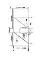
図7はスリット露光時のシャッター先幕、後幕の走行の様子と露光時間の関係を示した図であり、時刻t11においてシャッター先幕が走行を開始して撮像素子の上端から露光が開始される。次に、t11より所定時間遅れた時刻t12にシャッター後幕が走行を開始し、撮像素子の上端から遮光することによって前記露光を停止する。シャッター先幕および後幕の走行速度は同一となるように調整されており、撮像素子の上端から下端までの全ての領域において順次(t12−t11)なる所定時間Tdの露光が行われる。時刻t13およびt14はシャッター先幕および後幕の走行終了時刻であり、時間(t14−t13)も所定時間Tdとなっている。
【0004】
このようなスリット露光中にストロボ撮影を行おうとすると、図8に示すように画面の一部分の露光中にしかストロボ発光を行うことができなかったために露光むらを生じてしまうことから、従来ではフォーカルプレーンシャッターが全開する時間を有する長秒時でのみストロボ撮影が行われていた。しかし、近年のストロボ発光装置には従来に比べて長い時間一定の発光強度で発光させるいわゆるフラット発光モードを有するものが製品化されており、このモードを利用することによって、スリット露光となる高速シャッター時においてもストロボ撮影を行う事を可能にしている。
【0005】
図9は、フラット発光モードを有するストロボ発光装置を用いてスリット露光中にストロボ撮影を行う際の、シャッター先幕および後幕の動作とストロボ発光装置の発光の様子を示したものである。
【0006】
図9に従って動作を説明すると、ストロボ発光装置はシャッター先幕が走行開始する時刻t11よりも前の時刻t10で発光を開始する。この際、時刻t10とt11の間隔はストロボ発光装置の発光強度が安定するのに必要な所定時間に設定されている。すなわち、ストロボ発光装置の発光強度が安定してからシャッター先幕の走行が開始され、次に所定時間Tdを経た時刻t12にシャッター後幕が走行を開始する。さらにシャッター後幕の走行が時刻t14に終了するとストロボ発光装置の発光が停止される。このようにシャッター全開時間を有しない高速のシャッター秒時にもストロボ撮影が可能であった。
【0007】
【発明が解決しようとする課題】
しかしながら、上述のフォーカルプレーンシャッターを備えた静止画撮像装置においては、高速シャッター秒時でのストロボ撮影ではシャッター先幕の走行開始からシャッター後幕の走行終了までの間はストロボ発光装置を一定の強度で発光させているにもかかわらず、露光中の一時点に着目すれば撮像素子のごく一部にしかストロボ光が到達せず、残りはシャッター幕に吸収されてしまっていた。例えば図9において、露光時間(シャッター秒時)に相当する所定時間Tdを1ミリ秒、シャッター先幕および後幕の走行時間(t13−t11)=(t14−t12)を4ミリ秒とすると、安定したストロボ光を発光するフラット発光期間は少なくとも5ミリ秒必要となり、80%以上のエネルギーが無駄になっており、また、5ミリ秒もの長い時間フラット発光を行うために発光強度も制限せざるを得ないため、エネルギーロスが多く、更にはストロボ撮影の有効距離を示すガイドナンバーも小さくなるという欠点を有していた。
【0008】
(発明の目的)本発明の第1の目的は、照明手段の発光のエネルギーのロスを少なくし、高速のシャッター秒時でも撮影有効距離を損なう事無く適正な光量での照明撮影を行えるようにすることのできる静止画撮像装置を提供しようとするものである。
【0009】
本発明の第2の目的は、平坦な発光モードを有さず、急峻な発光モードで発光する照明手段を用いても、高速シャッター秒時での照明撮影を適正に行うことのできる静止画撮像装置を提供しようとするものである。
【0011】
【課題を解決するための手段】
上記第1の目的を達成するために、本発明は、蓄積時間を任意に制御し得る撮像素子と、第1のシャッター幕と第2のシャッター幕からなるフォーカルプレーンシャッターと、前記第1のシャッター幕が走行してから前記第2のシャッター幕が走行するまでの間に前記撮像素子に蓄積動作を行わせる撮像素子制御手段と、被写体を照明する照明手段とを備えた静止画撮像装置において、シャッター秒時が、前記フォーカルプレーンシャッターが全開する時間を有しない短秒時であり、前記照明手段の発光モードとしてフラット発光モードが設定されている時は、前記第1のシャッター幕の走行中に、前記照明手段によりフラット発光を開始させ、該フラット発光の発光強度が安定するタイミングに同期して、前記撮像素子制御手段が前記撮像素子に蓄積動作を行わせ、前記撮像素子の蓄積動作とフラット発光の終了に同期して、前記第2のシャッター幕が走行を開始する静止画撮像装置とするものである。
【0012】
上記第2の目的を達成するために、本発明は、蓄積時間を任意に制御し得る撮像素子と、第1のシャッター幕と第2のシャッター幕からなるフォーカルプレーンシャッターと、前記第1のシャッター幕が走行してから前記第2のシャッター幕が走行するまでの間に前記撮像素子に蓄積動作を行わせる撮像素子制御手段と、被写体を照明する照明手段とを備えた静止画撮像装置において、シャッター秒時が、前記フォーカルプレーンシャッターが全開する時間を有しない短秒時であり、前記照明手段の発光モードとして閃光発光モードが設定されている時は、前記第1のシャッター幕の走行終了に同期して、前記撮像素子制御せ、該閃光発光が所定量に達した後に閃光発光を停止させるとともに、前記シャッター秒時の経過直後に前記撮像素子制御手段が前記撮像素子の蓄積動作を停止させ、該蓄積動作の停止後、前記第2のシャッター幕は走行を開始する静止画撮像装置とするものである。
【0014】
【発明の実施の形態】
以下、本発明を図示の実施の形態に基づいて詳細に説明する。
【0015】
(実施の第1の形態)
図1は本発明の実施の第1の形態に係るフォーカルプレーンシャッターを備えた静止画撮像装置の電気的構成の概略を示すブロック図である。
【0016】
図1において、1は静止画撮像装置の各種の動作を制御する為の制御回路、2は画像記録媒体であるところの撮影素子(CCD)である。3はフォーカルプレーンシャッターを駆動するシャッター駆動装置であり、シャッター駆動回路及びシャッター先幕及びシャッター後幕等により構成される。4は内蔵もしくは外付けのストロボ発光装置であり、発光モードとして、通常の閃光発光モードとフラット発光モードを有している。5はレンズの焦点状態を検出し、該レンズのピント調節を行うためのオートフォーカス装置、6は露光時間(シャッター秒時)に相当する後述の所定時間Tdを求める為の測光情報を得る為の測光装置、7はオートフォーカス装置5や測光装置6を起動したり、露光動作を開始させる為のスイッチ等、各種のスイッチの状態を検出するスイッチ(SW)状態検出回路である。
【0017】
図2は、図1に示したフォーカルプレーンシャッターを備えた静止画撮像装置において、シャッター幕、撮像素子の蓄積、ストロボ発光装置の発光の様子を示したタイミングチャートであり、図3は実施の第1の形態における制御シーケンスを示したフローチャートである。なお、図3のシーケンスが開始される以前に、必要とされる露光時間およびストロボ発光強度は与えられているものとする。
【0018】
以下、図2のタイミングチャートを参照しながら、図3のフローチャートにしたがって主要部分の動作について説明する。
【0019】
図3のステップ#101にて露光シーケンスが開始されると、まずステップ#102にて、制御回路1はストロボ撮影モードか否かを判定する。この結果、ストロボ撮影モードではない場合はステップ#103へ進み、通常のシャッター制御による撮影を行い、ステップ#117にて露光動作を終了する。
【0020】
ここで、ストロボ発光装置4を用いない、通常のシャッター制御による撮影時について簡単に説明すると、この撮影時におけるシャッター秒時が、フォーカルプレーンシャッターが全開する時間を有しない短秒時、つまり高速シャッター秒時での撮影であった場合、フォーカルプレーンシャッターを用いたスリット露光を行うとともに、図9に示したように、撮像素子2の蓄積開始を該フォーカルプレーンシャッターの先幕走行開始以前とし、かつ撮像素子2の蓄積終了を該フォーカルプレーンシャッターの後幕走行終了後とするように制御する。
【0021】
一方、上記ステップ#102にてストロボ撮影モードであることを判定するとステップ#104へ進み、ここではシャッター秒時が高速シャッター秒時(演算により算出されるシャッタ秒時が、フォーカルプレーンシャッターが全開する時間を有しない短秒)か否かを判定し、高速シャッターでなければステップ#105へ進み、通常のシャッター制御およびストロボ制御による撮影を行い、ステップ#117にて露光動作を終了する。
【0022】
また、上記ステップ#104にて高速シャッター秒時であることを判定すると制御回路1はステップ#106へ動作を進め、ストロボ発光モードをフラット発光モードにするとともに所定のフラット発光強度をストロボ発光装置4に設定する。そして、次のステップ#107にて、図2に示す時刻t1にてシャッター駆動装置3を駆動してシャッター先幕を走行させる。続くステップ#108では、図2に示す時刻t3−Tsに達したか否かを判定し、達していなければステップ#109にて時刻t3−Tsに達するまで待機し、その後ステップ#108へ戻り、ここでは既に時刻t3−Tsに達しているので直ちにステップ#110へ進み、シャッター先幕走行終了時刻t3よりも所定時間だけ早いタイミング(t3−Tsのタイミング)でストロボ発光装置4にストロボ発光を開始させる。ここで上記Tsは、ストロボ発光装置4の発光強度が安定するのに要する時間である。
【0023】
次のステップ#111では、制御回路1は図2に示すようにシャッター先幕走行終了時刻t3には既にストロボ発光装置4の発光強度は安定しているので、撮像素子(CCD)2の蓄積を開始する。そして、次のステップ#114,#115にて、予め測光装置6による測光結果をもとに与えられたシャッター秒時に相当する所定時間Tdが経過するのを待機し、上記所定時間Tdが経過すると、ステップ#114からステップ#116へ進み、前記撮像素子2の蓄積およびストロボ発光装置4の発光を停止するとともに、シャッター後幕の走行を開始する(図1の時刻t2)。その後、シャッター後幕の走行が終了するとステップ#117へ進み、露光動作を終了する。
【0024】
以上の実施の第1の形態によれば、フォーカルプレーンシャッターの全開時間を有しない高速のシャッター秒時(測光情報等に基づいて演算により算出されたシャッタ秒時)におけるストロボ撮影において、シャッター先幕走行終了後にストロボ発光装置4をフラット発光させるとともに撮像素子2の蓄積を開始し(図1の時刻t3のタイミング、図2のステップ#108→#110)、前記高速シャッタ秒時後にストロボ発光装置4の発光および撮像素子2の蓄積を停止した後にシャッター後幕を走行させる(図1の時刻t3から露光(蓄積)時間Tdの経過後の時刻t2のタイミング、図2のステップ#114→#116)ような構成にしている。
【0025】
よって、ストロボ発光装置4の発光のエネルギーロスが少なく、また高速シャッター時でも撮影有効距離を損なう事無く適正な光量でのストロボ撮影を行える静止画撮像装置とすることができる。
【0026】
(実施の第2の形態)
図4は、本発明の実施の第2の形態に係る静止画撮像装置において、シャッター幕、撮像素子の蓄積、ストロボ発光装置の発光の様子を示したタイミングチャートであり、図5は実施の第2の形態の制御シーケンスを示したフローチャートである。なお、図5のシーケンスが開始される以前に必要とされる露光時間およびストロボ発光強度は与えられているものとする。又静止画撮像装置の回路構成は図1と同じであるものとし、ストロボ発光装置は、閃光発光モードのみ設定できるものとする。
【0027】
以下、図4のタイミングチャートを参照しながら、図5のフローチャートにしたがって主要部分の動作について説明する。
【0028】
ステップ#201にて露光シーケンスが開始されると、まずステップ#202にて、制御回路1はストロボ撮影モードか否かを判定する。この結果、ストロボ撮影モードではない場合はステップ#203へ進み、通常のシャッター制御による撮影を行い、ステップ#216にて露光動作を終了する。一方、上記ステップ#202にてストロボ撮影モードであることを判定するとステップ#204へ進み、ここではシャッター秒時が高速シャッター秒時か否かを判定し、高速シャッター秒時でなければステップ#206へ進み、通常のシャッター制御およびストロボ制御による撮影を行い、ステップ#216にて露光動作を終了する。
【0029】
また、上記ステップ#204にて高速シャッター秒時であることを判定すると制御回路1はステップ#205へ動作を進め、図4に示す時刻t1にてシャッター駆動装置3を駆動してシャッター先幕を走行させ、続くステップ#207では、図4に示す時刻t3に達したか否かを判定し、達していなければステップ#208にて時刻t3に達するまで待機し、その後ステップ#207へ戻り、ここでは既に時刻t3に達しているので直ちにステップ#209へ進む。
【0030】
ステップ#209へ進むと、制御回路1は撮像素子2の蓄積を開始するとともにストロボ発光装置4を閃光発光(図2に示したフラット発光とは異なる)させ、次のステップ#210,#211にて、ストロボ発光装置4の発光が所定量に達する(発光量の積分値が所定の値に達する)まで待機し、ストロボ発光装置4での発光が所定量に達するとステップ#210からステップ#212へ進み、前記閃光発光を停止する。そして、次のステップ#213,#214にて、予め測光装置6による測光結果をもとに与えられたシャッター秒時と同一の時間Tdが経過するのを待機し、上記時間Tdが経過すると、ステップ#213からステップ#215へ進み、前記撮像素子2の蓄積を停止するとともに、シャッター後幕の走行を開始する(図4の時刻t2)。その後、シャッター後幕の走行が終了するとステップ#216へ進み、露光動作を終了する。
【0031】
以上の実施の第2の形態によれば、フォーカルプレーンシャッターの全開時間を有しない高速のシャッター秒時におけるストロボ撮影において、シャッター先幕走行終了後に撮像素子2の蓄積を開始するとともにストロボ発光装置4を閃光発光させ(図4の時刻t3のタイミング、図5のステップ#207→#209)、ストロボ発光装置4の発光が所定量に達した後にその発光を停止させる(図5のステップ#212)とともに、前記シャッタ秒時の経過直後に撮像素子2の蓄積を停止し、その後に直ちにシャッター後幕を走行させる(図4の時刻t3から露光(蓄積)時間Tdの経過後の時刻t2のタイミング、図5のステップ#213→#215)ような構成にしている。
【0032】
よって、閃光発光モードで発光するストロボ発光装置4を用いても、高速シャッター時のストロボ撮影を行える静止画撮像装置とすることができる。
【0033】
(実施の第3の形態)
図6は、本発明の実施の第3の形態に係る静止画撮像装置の主要部分の制御シーケンスを示したフローチャートである。なお、図6のシーケンスが開始される以前に必要とされる露光時間およびストロボ発光強度は与えられているものとする。又静止画撮像装置の回路構成は図1と同じであるものとする。
【0034】
以下、前述の図2及び図4のタイミングチャートを参照しながら、図6のフローチャートにしたがって主要部分の動作について説明する。
【0035】
ステップ#301にて露光シーケンスが開始されると、まずステップ#302にて、制御回路1はストロボ撮影モードか否かを判定する。この結果、ストロボ撮影モードではない場合はステップ#303へ進み、通常のシャッター制御による撮影を行い、ステップ#318にて露光動作を終了する。一方、上記ステップ#302にてストロボ撮影モードであることを判定するとステップ#304へ進み、ここではシャッター秒時が高速シャッター秒時か否かを判定し、高速シャッター秒時でなければステップ#306へ進み、通常のシャッター制御およびストロボ制御による撮影を行い、ステップ#318にて露光動作を終了する。
【0036】
また、上記ステップ#304にて高速シャッター秒時であることを判定すると制御回路1はステップ#306へ動作を進め、ここでは必要とされる発光強度がフラット発光で得られるか否かを被写体距離等により判定し、フラット発光モードで必要な発光強度が得られる場合にはステップ#307へ進み、ストロボ発光装置4をフラット発光モードに設定するとともに所定のフラット発光強度を設定し、次のステップ#308にて、図2に示す時刻t1にてシャッター先幕を走行させる。続くステップ#309では、図2に示す時刻t3−Tsに達したか否かを判定し、達していなければステップ#310にて時刻t3−Tsに達するまで待機し、その後ステップ#309へ戻り、ここでは既に時刻t3−Tsに達しているので直ちにステップ#311へ進み、シャッター先幕走行終了時刻t3よりも所定時間だけ早いタイミング(t3−Tsのタイミング)でストロボ発光装置4にストロボ発光を開始させる。ここで上記Tsは、ストロボ発光装置4の発光強度が安定するのに要する時間である。
【0037】
次のステップ#312では、制御回路1は図2に示すようにシャッター先幕走行終了時刻t3には既にストロボ発光装置4の発光強度が安定しているので、撮像素子2(CCD)の蓄積を開始する。そして、次のステップ#315,#316にて、予め測光装置6による測光結果をもとに与えられたシャッター秒時と同一の時間Tdが経過するのを待機し、上記時間Tdが経過すると、ステップ#315からステップ#317へ進み、前記撮像素子2の蓄積およびストロボ発光装置4の発光を停止するとともに、シャッター後幕の走行を開始する(図1の時刻t2)。その後、シャッター後幕の走行が終了するとステップ#318へ進み、露光動作を終了する。
【0038】
また、上記ステップ#306にて、フラット発光モードでは必要な発光強度が得られない場合には制御回路1はステップ#319へ動作を進め、ストロボ発光装置4を閃光発光モードにセットする。そして、次のステップ#320にて、図4に示す時刻t1でシャッター先幕を走行させ、続くステップ#321にて、図4に示す時刻t3に達したか否かを判定し、達していなければステップ#322にて時刻t3に達するまで待機し、その後ステップ#321へ戻り、ここでは既に時刻t3に達しているので直ちにステップ#323へ進む。
【0039】
ステップ#323へ進むと、制御回路1は撮像素子2の蓄積を開始するとともにストロボ発光装置4を閃光発光させ、次のステップ#324,#325にて、ストロボ発光装置4の発光が所定量に達する(発光量の積分値が所定の値に達する)まで待機し、ストロボ発光装置4での発光が所定量に達するとステップ#324からステップ#326へ進み、前記閃光発光を停止する。そして、次のステップ#327,#328にて、予め測光装置6による測光結果をもとに与えられたシャッター秒時と同一の時間Tdが経過するのを待機し、上記時間Tdが経過すると、ステップ#213からステップ#215へ進み、前記撮像素子2の蓄積を停止するとともに、シャッター後幕の走行を開始する(図4の時刻t2)。その後、シャッター後幕の走行が終了するとステップ#318へ進み、露光動作を終了する。
【0040】
以上の実施の第3の形態によれば、フォーカルプレーンシャッターの全開時間を有しない高速のシャッター秒時におけるストロボ撮影において、フラット発光で必要とされる発光強度が得られる場合(例えば被写体距離が所定の距離よりも近い場合)には、シャッター先幕走行終了後にストロボ発光装置4をフラット発光させるとともに撮像素子2の蓄積を開始し、所定時間後に前記ストロボ発光装置4の発光および撮像素子2の蓄積を停止してシャッター後幕を走行させるように制御(図5のステップ#306〜#317)し、一方、フラット発光では必要とされる発光強度が得られない場合(例えば被写体距離が所定の距離よりも遠い場合)には、シャッター先幕走行終了後に撮像素子2の蓄積を開始するとともにストロボ発光装置4を閃光発光させ、所定発光量発光後に前記ストロボ発光装置4の発光を停止させるとともに、所定の蓄積時間経過後に撮像素子2の蓄積を停止し、その後にシャッター後幕を走行させるように制御(図5のステップ#306→#319〜#329)する構成にしている。
【0041】
よって、必要とされる発光強度が低い時には、高い精度で発光量を制御するとともに、必要とされる発光強度が高い場合には、閃光発光モードを用いて大光量でストロボ撮影を行える静止画撮影装置とすることができるものである。
【0042】
【発明の効果】
以上説明したように、本発明によれば、照明手段の発光のエネルギーのロスを少なくし、高速のシャッター秒時でも撮影有効距離を損なう事無く適正な光量での照明撮影を行えるようにすることができる静止画撮像装置を提供できるものである。
【0043】
さらに、本発明によれば、平坦な発光モードを有さず、急峻な発光モードで発光する照明手段を用いても、高速シャッター秒時での照明撮影を適正に行うことができる静止画撮像装置を提供できるものである。
【図面の簡単な説明】
【図1】本発明の実施の各形態に係る静止画撮像装置の概略構成を示すブロック図である。
【図2】本発明の実施の第1の形態に係る静止画撮像装置のシャッター幕、撮像素子の蓄積、ストロボ発光装置の発光の様子を示すタイミングチャートである。
【図3】本発明の実施の第1の形態での制御シーケンスを示すフローチャートである。
【図4】本発明の実施の第1の形態に係る静止画撮像装置のシャッター幕、撮像素子の蓄積、ストロボ発光装置の発光の様子を示すタイミングチャートである。
【図5】本発明の実施の第2の形態での制御シーケンスを示すフローチャートである。
【図6】本発明の実施の第3の形態での制御シーケンスを示すフローチャートである。
【図7】従来のスリット露光時のシャッター幕の様子を示す図である。
【図8】従来のスリット露光時にストロボ発光装置を閃光発光させた場合のシャッター幕、撮像素子の蓄積、ストロボ発光装置の発光の様子を示すタイミングチャートである。
【図9】従来のスリット露光時にストロボ撮影する際のシャッター幕、撮像素子の蓄積、ストロボ発光装置の発光の様子を示すタイミングチャートである。
【符号の説明】
1 制御回路
2 撮像素子
3 シャッター駆動装置
4 ストロボ発光装置
6 測光装置
Td 露光時間に相当する所定時間[0001]
BACKGROUND OF THE INVENTION
The present invention relates to an improvement of a still image capturing apparatus including a shutter device such as a focal plane shutter and an illumination unit such as a strobe light emitting device.
[0002]
[Prior art]
In a still image pickup apparatus provided with a focal plane shutter, slit exposure is performed at a short time when the focal plane shutter does not fully open, that is, at a high-speed shutter time.
[0003]
FIG. 7 is a diagram showing the relationship between the shutter front curtain and rear curtain traveling during the slit exposure and the exposure time. At time t11, the shutter front curtain starts traveling and exposure starts from the upper end of the image sensor. The Next, at time t12, which is a predetermined time later than t11, the shutter rear curtain starts running, and the exposure is stopped by shielding light from the upper end of the image sensor. The traveling speeds of the shutter front curtain and the rear curtain are adjusted to be the same, and exposure for a predetermined time Td of (t12-t11) is sequentially performed in all areas from the upper end to the lower end of the image sensor. Times t13 and t14 are the travel end times of the shutter front curtain and the rear curtain, and the time (t14-t13) is also a predetermined time Td.
[0004]
If an attempt is made to perform flash photography during such slit exposure, since the flash emission could only occur during the exposure of a portion of the screen as shown in FIG. The flash photography was performed only in a long time when the plain shutter was fully open. However, recent strobe light emitting devices have been commercialized that have a so-called flat light emission mode that emits light at a constant light intensity for a longer time than in the past, and by using this mode, a high-speed shutter that provides slit exposure Even at times, it is possible to perform flash photography.
[0005]
FIG. 9 shows the operation of the shutter front curtain and rear curtain and the state of light emission of the strobe light emission device when performing strobe photography during slit exposure using a strobe light emission device having a flat light emission mode .
[0006]
The operation will be described with reference to FIG. 9. The strobe light emitting device starts light emission at time t10 before time t11 when the shutter front curtain starts to travel. At this time, the interval between times t10 and t11 is set to a predetermined time necessary for stabilizing the light emission intensity of the strobe light emitting device. That is, the shutter front curtain starts traveling after the light emission intensity of the strobe light emitting device is stabilized, and the shutter rear curtain starts traveling at time t12 after a predetermined time Td. Further, when the running of the shutter rear curtain ends at time t14 , the light emission of the strobe light emitting device is stopped. In this way, flash photography was possible even at high shutter speeds that did not have the shutter fully open time.
[0007]
[Problems to be solved by the invention]
However, in the above-described still image capturing device equipped with the focal plane shutter, the strobe light emitting device has a certain intensity during the period from the start of the shutter front curtain to the end of the shutter rear curtain during strobe shooting at high shutter speeds. In spite of the fact that the flash light is emitted, the strobe light reaches only a small part of the image sensor when focusing on one point during the exposure, and the rest is absorbed by the shutter curtain. For example, in FIG. 9, when the predetermined time Td corresponding to the exposure time (shutter time) is 1 millisecond and the travel time (t13-t11) = (t14-t12) of the shutter front curtain and rear curtain is 4 milliseconds, The flat light emission period for emitting stable strobe light requires at least 5 milliseconds, 80% or more of energy is wasted, and the light emission intensity must be limited to perform flat light emission for as long as 5 milliseconds. Therefore, the energy loss is large, and the guide number indicating the effective distance for flash photography is also small.
[0008]
(Object of the Invention) The first object of the present invention is to reduce the loss of light emitted from the illumination means so that illumination photography can be performed with an appropriate amount of light without impairing the effective photographing distance even at high shutter speeds. It is an object of the present invention to provide a still image capturing apparatus that can perform such a process.
[0009]
A second object of the present invention is to capture a still image that can appropriately perform illumination photography at a high shutter speed even when using illumination means that does not have a flat light emission mode and emits light in a steep light emission mode. The device is to be provided.
[0011]
[Means for Solving the Problems]
In order to achieve the first object, the present invention provides an image sensor capable of arbitrarily controlling the accumulation time, a focal plane shutter including a first shutter curtain and a second shutter curtain, and the first shutter. and imaging element control means for causing the storage operation on the imaging element between the traveling curtain to the second shutter curtain travels, in the still image capturing apparatus provided with an illuminating means for illuminating the subject, When the shutter time is a short time when the focal plane shutter does not fully open, and the flat light emission mode is set as the light emission mode of the illumination means, the first shutter curtain is running. , to initiate the flat light emission by the illumination means, in synchronism with the timing at which the emission intensity of the flat emission is stabilized, the imaging element control means said imaging To perform the storage operation to the child, in synchronization with the completion of the storage operation and flat emission of the imaging element, the second shutter curtain is intended to a still image capturing device starts running.
[0012]
In order to achieve the second object, the present invention provides an image sensor that can arbitrarily control an accumulation time, a focal plane shutter that includes a first shutter curtain and a second shutter curtain, and the first shutter. In a still image pickup apparatus comprising: an image sensor control unit that causes the image sensor to perform a storage operation between a curtain traveling and a time when the second shutter curtain travels; and an illumination unit that illuminates a subject. When the shutter time is a short time when the focal plane shutter does not fully open, and the flashing mode is set as the lighting mode of the illumination means, the first shutter curtain travel ends. synchronously, the imaging element was controlled with該閃light emission stops the flash light emission after a predetermined amount, the image sensor immediately after the passage of time the shutter speed Control means to stop the accumulation operation of the image pickup element, after stopping of the storage operation, the second shutter curtain is to a still image capturing device starts running.
[0014]
DETAILED DESCRIPTION OF THE INVENTION
Hereinafter, the present invention will be described in detail based on illustrated embodiments.
[0015]
(First embodiment)
FIG. 1 is a block diagram showing an outline of an electrical configuration of a still image pickup apparatus including a focal plane shutter according to the first embodiment of the present invention.
[0016]
In FIG. 1, reference numeral 1 denotes a control circuit for controlling various operations of the still image pickup apparatus, and 2 denotes a photographing element (CCD) as an image recording medium. A
[0017]
FIG. 2 is a timing chart showing the shutter curtain, storage of the image sensor, and light emission of the strobe light emitting device in the still image imaging device including the focal plane shutter shown in FIG. It is the flowchart which showed the control sequence in 1 form. It is assumed that the required exposure time and strobe emission intensity are given before the sequence of FIG. 3 is started.
[0018]
Hereinafter, the operation of the main part will be described according to the flowchart of FIG. 3 with reference to the timing chart of FIG.
[0019]
When the exposure sequence is started in
[0020]
Here, a brief description will be given of shooting at normal shutter control without using the strobe light emitting device 4. The shutter time at the time of shooting is a short time when the focal plane shutter does not fully open, that is, a high-speed shutter. In the case of shooting at the second time, the slit exposure using the focal plane shutter is performed, and as shown in FIG. 9, the accumulation start of the
[0021]
On the other hand, if it is determined in
[0022]
If it is determined in
[0023]
In the
[0024]
According to the first embodiment described above, in the strobe shooting at high shutter speed (shutter time calculated by calculation based on photometric information) that does not have the full open time of the focal plane shutter, the shutter front curtain After the travel is completed, the strobe light emitting device 4 is caused to emit flat light and the
[0025]
Therefore, it is possible to provide a still image capturing device that can perform strobe shooting with an appropriate amount of light without impairing the effective shooting distance even when a high-speed shutter is used.
[0026]
(Second Embodiment)
FIG. 4 is a timing chart showing a shutter curtain, accumulation of an image sensor, and light emission of a strobe light emitting device in a still image imaging device according to a second embodiment of the present invention. FIG. 6 is a flowchart showing a control sequence of the second form. It is assumed that the exposure time and strobe emission intensity required before the sequence of FIG. 5 is started are given. The circuit configuration of the still image pickup device is the same as that in FIG. 1, and the strobe light emitting device can be set only in the flash light emission mode.
[0027]
Hereinafter, the operation of the main part will be described according to the flowchart of FIG. 5 with reference to the timing chart of FIG.
[0028]
When the exposure sequence is started in
[0029]
If it is determined in
[0030]
In
[0031]
According to the second embodiment described above, in strobe shooting at a high shutter speed that does not have the fully open time of the focal plane shutter, accumulation of the
[0032]
Therefore, even if the strobe light emitting device 4 that emits light in the flash emission mode is used, a still image capturing device capable of performing strobe photography at a high shutter speed can be obtained.
[0033]
(Third embodiment)
FIG. 6 is a flowchart showing a control sequence of the main part of the still image capturing apparatus according to the third embodiment of the present invention. It is assumed that the exposure time and strobe emission intensity required before the sequence of FIG. 6 is started are given. The circuit configuration of the still image capturing apparatus is the same as that in FIG.
[0034]
Hereinafter, the operation of the main part will be described according to the flowchart of FIG. 6 with reference to the timing charts of FIG. 2 and FIG.
[0035]
When the exposure sequence is started in
[0036]
If it is determined in
[0037]
In the
[0038]
If the necessary light emission intensity cannot be obtained in the flat light emission mode in
[0039]
In
[0040]
According to the third embodiment described above, when the light emission intensity required for flat light emission is obtained in strobe shooting at a high shutter speed that does not have the full open time of the focal plane shutter (for example, the subject distance is predetermined). When the shutter front curtain travel ends, the strobe light emitting device 4 is caused to emit flat light and the
[0041]
Therefore, when the required light emission intensity is low, the amount of light emission is controlled with high accuracy, and when the required light emission intensity is high, still image shooting can be performed with a large amount of light using the flash emission mode. It can be a device.
[0042]
【The invention's effect】
As described above, according to the present invention, it is possible to reduce the loss of light emission energy of the illumination means , and to perform illumination shooting with an appropriate light amount without losing the effective shooting distance even at a high shutter speed. It is possible to provide a still image capturing apparatus capable of
[0043]
Furthermore , according to the present invention , a still image capturing apparatus capable of appropriately performing illumination photography at a high shutter speed even when using illumination means that does not have a flat light emission mode and emits light in a steep light emission mode. Can be provided.
[Brief description of the drawings]
FIG. 1 is a block diagram showing a schematic configuration of a still image capturing apparatus according to each embodiment of the present invention.
FIG. 2 is a timing chart showing a shutter curtain, image sensor accumulation, and light emission of a strobe light emitting device of the still image capturing device according to the first embodiment of the present invention.
FIG. 3 is a flowchart showing a control sequence according to the first embodiment of the present invention.
FIG. 4 is a timing chart showing a shutter curtain, image sensor accumulation, and light emission of the strobe light emitting device of the still image capturing device according to the first embodiment of the present invention.
FIG. 5 is a flowchart showing a control sequence according to the second embodiment of the present invention.
FIG. 6 is a flowchart showing a control sequence according to the third embodiment of the present invention.
FIG. 7 is a diagram illustrating a state of a shutter curtain during conventional slit exposure.
FIG. 8 is a timing chart showing a shutter curtain, image sensor accumulation, and light emission of the strobe light emitting device when the strobe light emitting device is caused to flash during conventional slit exposure.
FIG. 9 is a timing chart showing a shutter curtain, accumulation of an image sensor, and light emission of a strobe light emitting device during strobe photography during conventional slit exposure.
[Explanation of symbols]
DESCRIPTION OF SYMBOLS 1
Claims (4)
シャッター秒時が、前記フォーカルプレーンシャッターが全開する時間を有しない短秒時であり、前記照明手段の発光モードとしてフラット発光モードが設定されている時は、前記第1のシャッター幕の走行中に、前記照明手段によりフラット発光を開始させ、該フラット発光の発光強度が安定するタイミングに同期して、前記撮像素子制御手段は前記撮像素子に蓄積動作を行わせ、前記撮像素子の蓄積動作とフラット発光の終了に同期して、前記第2のシャッター幕は走行を開始することを特徴とする静止画撮像装置。An image sensor that can arbitrarily control the accumulation time, a focal plane shutter composed of a first shutter curtain and a second shutter curtain, and the second shutter curtain travel after the first shutter curtain travels. In the still image pickup apparatus including an image pickup device control unit that causes the image pickup device to perform a storage operation until and an illumination unit that illuminates the subject.
When the shutter time is a short time when the focal plane shutter does not fully open, and the flat light emission mode is set as the light emission mode of the illumination means, the first shutter curtain is running. The illumination unit starts flat light emission, and in synchronization with the timing at which the emission intensity of the flat light emission is stabilized, the image sensor control unit causes the image sensor to perform an accumulation operation. The still image pickup apparatus, wherein the second shutter curtain starts running in synchronization with the end of light emission.
シャッター秒時が、前記フォーカルプレーンシャッターが全開する時間を有しない短秒時であり、前記照明手段の発光モードとして閃光発光モードが設定されている時は、前記第1のシャッター幕の走行終了に同期して、前記撮像素子制御手段は前記撮像素子の蓄積動作を開始させるとともに、前記照明手段は閃光発光を開始させ、該閃光発光が所定量に達した後に閃光発光を停止させるとともに、前記シャッター秒時の経過直後に前記撮像素子制御手段は前記撮像素子の蓄積動作を停止させ、該蓄積動作の停止後、前記第2のシャッター幕は走行を開始することを特徴とする静止画撮像装置。An image sensor that can arbitrarily control the accumulation time, a focal plane shutter composed of a first shutter curtain and a second shutter curtain, and the second shutter curtain travel after the first shutter curtain travels. In the still image pickup apparatus including an image pickup device control unit that causes the image pickup device to perform a storage operation until and an illumination unit that illuminates the subject.
When the shutter time is a short time when the focal plane shutter does not fully open, and the flashing mode is set as the lighting mode of the illumination means, the first shutter curtain travel ends. In synchronism, the image sensor control means starts the accumulation operation of the image sensor, the illumination means starts flash light emission, stops the flash light emission after the flash light emission reaches a predetermined amount, and the shutter Immediately after the elapse of seconds, the image sensor control means stops the accumulation operation of the image sensor, and after the accumulation operation stops, the second shutter curtain starts running.
Priority Applications (4)
| Application Number | Priority Date | Filing Date | Title |
|---|---|---|---|
| JP2002050653A JP4298208B2 (en) | 2002-02-27 | 2002-02-27 | Still image pickup device |
| US10/372,702 US7336307B2 (en) | 2002-02-27 | 2003-02-24 | Camera having accumulation operation in the period between the time of fully opening a leading shutter and the time of starting of a trailing shutter |
| CNB031047025A CN1317601C (en) | 2002-02-27 | 2003-02-25 | Camera |
| EP03004153A EP1341376A3 (en) | 2002-02-27 | 2003-02-26 | Camera |
Applications Claiming Priority (1)
| Application Number | Priority Date | Filing Date | Title |
|---|---|---|---|
| JP2002050653A JP4298208B2 (en) | 2002-02-27 | 2002-02-27 | Still image pickup device |
Publications (3)
| Publication Number | Publication Date |
|---|---|
| JP2003259197A JP2003259197A (en) | 2003-09-12 |
| JP2003259197A5 JP2003259197A5 (en) | 2005-09-02 |
| JP4298208B2 true JP4298208B2 (en) | 2009-07-15 |
Family
ID=27678496
Family Applications (1)
| Application Number | Title | Priority Date | Filing Date |
|---|---|---|---|
| JP2002050653A Expired - Fee Related JP4298208B2 (en) | 2002-02-27 | 2002-02-27 | Still image pickup device |
Country Status (4)
| Country | Link |
|---|---|
| US (1) | US7336307B2 (en) |
| EP (1) | EP1341376A3 (en) |
| JP (1) | JP4298208B2 (en) |
| CN (1) | CN1317601C (en) |
Families Citing this family (9)
| Publication number | Priority date | Publication date | Assignee | Title |
|---|---|---|---|---|
| CA2616030A1 (en) * | 2005-07-20 | 2007-01-25 | Lab Partners Associates, Inc. | Wireless photographic communication system and method |
| JP4999306B2 (en) * | 2005-09-30 | 2012-08-15 | カシオ計算機株式会社 | Imaging apparatus, imaging method, and program |
| WO2008150902A1 (en) | 2007-05-29 | 2008-12-11 | Lab Partners Associates, Inc. | System and method for maintaining hot shoe communications between a camera and a wireless device |
| US8917350B2 (en) * | 2009-02-12 | 2014-12-23 | Lab Patners Associates, Inc. | Early photographic synchronization system and method |
| US8718461B2 (en) | 2009-02-12 | 2014-05-06 | Lab Partners Associates, Inc. | Photographic synchronization optimization system and method |
| US8614766B1 (en) | 2009-02-12 | 2013-12-24 | Lab Partners Associates, Inc. | Systems and methods for controlling a power state of a remote device using camera body backlighting control signaling |
| TWI594629B (en) * | 2013-11-01 | 2017-08-01 | 佳世達科技股份有限公司 | Photographic apparatus with illumination supplement adjustment function and method using the same |
| US9690169B2 (en) | 2013-11-04 | 2017-06-27 | Lab Partners Associates, Inc. | Photographic lighting system and method |
| EP4057061A4 (en) * | 2019-12-16 | 2022-12-28 | Sony Group Corporation | Photographing system, control method, and program |
Family Cites Families (19)
| Publication number | Priority date | Publication date | Assignee | Title |
|---|---|---|---|---|
| US4589023A (en) * | 1982-12-20 | 1986-05-13 | Asahi Kogaku Kogyo Kabushiki Kaisha | Electronic camera |
| JPH0695733B2 (en) * | 1986-12-25 | 1994-11-24 | 富士写真フイルム株式会社 | Electronic still camera |
| US5012271A (en) * | 1987-03-12 | 1991-04-30 | Canon Kabushiki Kaisha | Exposure control device |
| US5023723A (en) * | 1988-04-18 | 1991-06-11 | Canon Kabushiki Kaisha | Image sensing apparatus having plural image sensors and plural shutters |
| JPH04226437A (en) * | 1990-08-13 | 1992-08-17 | Olympus Optical Co Ltd | Camera |
| US5410225A (en) * | 1991-08-30 | 1995-04-25 | Aiwa Co., Ltd. | Video camera and camera system employing aperture control |
| JPH07287278A (en) * | 1994-05-09 | 1995-10-31 | Nikon Corp | Electric flashing device |
| US5678098A (en) * | 1994-06-09 | 1997-10-14 | Fuji Photo Film Co., Ltd. | Method and apparatus for controlling exposure of camera |
| KR100322254B1 (en) * | 1994-07-22 | 2002-07-02 | 이중구 | Camera to reduce charging time of electric flash and control method thereof |
| JPH08160492A (en) * | 1994-12-09 | 1996-06-21 | Canon Inc | Camera |
| JPH08184882A (en) * | 1995-01-05 | 1996-07-16 | Canon Inc | Camera |
| US6067422A (en) * | 1995-07-28 | 2000-05-23 | Canon Kabushiki Kaisha | Flash photography system |
| JPH0968742A (en) * | 1995-08-31 | 1997-03-11 | Nissin Electric Co Ltd | Photographing device |
| JP3907260B2 (en) * | 1997-03-11 | 2007-04-18 | キヤノン株式会社 | camera |
| JPH1184489A (en) * | 1997-09-09 | 1999-03-26 | Olympus Optical Co Ltd | Stroboscope device |
| US6404987B1 (en) * | 1998-09-07 | 2002-06-11 | Canon Kabushiki Kaisha | Flash system |
| US6295413B1 (en) * | 1999-02-24 | 2001-09-25 | Nikon Corporation | Digitizing circuit of light amount receiving from strobe and control circuit of light amount emitted from strobe |
| JP2002095015A (en) * | 2000-09-11 | 2002-03-29 | Canon Inc | Image pickup system, lens unit and imaging device |
| US6801257B2 (en) * | 2001-01-12 | 2004-10-05 | Cognitens Ltd. | Optical three-dimensional digital imaging and mensuration system for industrial applications |
-
2002
- 2002-02-27 JP JP2002050653A patent/JP4298208B2/en not_active Expired - Fee Related
-
2003
- 2003-02-24 US US10/372,702 patent/US7336307B2/en not_active Expired - Fee Related
- 2003-02-25 CN CNB031047025A patent/CN1317601C/en not_active Expired - Fee Related
- 2003-02-26 EP EP03004153A patent/EP1341376A3/en not_active Withdrawn
Also Published As
| Publication number | Publication date |
|---|---|
| EP1341376A3 (en) | 2008-02-13 |
| JP2003259197A (en) | 2003-09-12 |
| US7336307B2 (en) | 2008-02-26 |
| CN1444085A (en) | 2003-09-24 |
| EP1341376A2 (en) | 2003-09-03 |
| US20030161621A1 (en) | 2003-08-28 |
| CN1317601C (en) | 2007-05-23 |
Similar Documents
| Publication | Publication Date | Title |
|---|---|---|
| JP4872346B2 (en) | CAMERA SYSTEM AND CAMERA LIGHTING DEVICE | |
| JP3733282B2 (en) | Imaging device, imaging method, and medium for supplying imaging device control program | |
| JP4298208B2 (en) | Still image pickup device | |
| JP4151264B2 (en) | Camera system | |
| JP2016038522A (en) | Illumination device, imaging device and camera system | |
| JP2009265269A (en) | Illuminator for photography and photographic device | |
| US7505077B2 (en) | Lighting control apparatus | |
| JP4872170B2 (en) | Camera system | |
| JP3569942B2 (en) | Image stabilization camera | |
| JP2006106201A (en) | Camera | |
| JPH11119304A (en) | Camera system | |
| JP4754745B2 (en) | Camera with strobe device | |
| JP2009055491A (en) | Imaging apparatus and control method thereof | |
| JP4174280B2 (en) | camera | |
| JP2008003499A (en) | Focus detecting device, camera, and focus detecting method | |
| JP3145508B2 (en) | Electronic still camera | |
| JPH089717Y2 (en) | Slow syncable camera | |
| JP2005326566A (en) | Camera and control method therefor, program and storage medium thereof | |
| JP5228987B2 (en) | Electronic camera | |
| JP2003121905A (en) | Photographic device with red-eye effect reducing function | |
| JP2004361445A (en) | Flashing device | |
| JPH1195093A (en) | Focus detecting device for camera | |
| JP2000131597A (en) | Electronic camera | |
| JPH04158344A (en) | Camera capable of partially tuned photographing | |
| JPH06189315A (en) | Still picture pickup method and its device |
Legal Events
| Date | Code | Title | Description |
|---|---|---|---|
| A521 | Request for written amendment filed |
Free format text: JAPANESE INTERMEDIATE CODE: A523 Effective date: 20050225 |
|
| A621 | Written request for application examination |
Free format text: JAPANESE INTERMEDIATE CODE: A621 Effective date: 20050225 |
|
| A977 | Report on retrieval |
Free format text: JAPANESE INTERMEDIATE CODE: A971007 Effective date: 20070807 |
|
| A131 | Notification of reasons for refusal |
Free format text: JAPANESE INTERMEDIATE CODE: A131 Effective date: 20070814 |
|
| A521 | Request for written amendment filed |
Free format text: JAPANESE INTERMEDIATE CODE: A523 Effective date: 20071011 |
|
| A131 | Notification of reasons for refusal |
Free format text: JAPANESE INTERMEDIATE CODE: A131 Effective date: 20080430 |
|
| A521 | Request for written amendment filed |
Free format text: JAPANESE INTERMEDIATE CODE: A523 Effective date: 20080627 |
|
| TRDD | Decision of grant or rejection written | ||
| A01 | Written decision to grant a patent or to grant a registration (utility model) |
Free format text: JAPANESE INTERMEDIATE CODE: A01 Effective date: 20090414 |
|
| A01 | Written decision to grant a patent or to grant a registration (utility model) |
Free format text: JAPANESE INTERMEDIATE CODE: A01 |
|
| A61 | First payment of annual fees (during grant procedure) |
Free format text: JAPANESE INTERMEDIATE CODE: A61 Effective date: 20090415 |
|
| R150 | Certificate of patent or registration of utility model |
Free format text: JAPANESE INTERMEDIATE CODE: R150 |
|
| FPAY | Renewal fee payment (event date is renewal date of database) |
Free format text: PAYMENT UNTIL: 20120424 Year of fee payment: 3 |
|
| FPAY | Renewal fee payment (event date is renewal date of database) |
Free format text: PAYMENT UNTIL: 20130424 Year of fee payment: 4 |
|
| FPAY | Renewal fee payment (event date is renewal date of database) |
Free format text: PAYMENT UNTIL: 20130424 Year of fee payment: 4 |
|
| FPAY | Renewal fee payment (event date is renewal date of database) |
Free format text: PAYMENT UNTIL: 20140424 Year of fee payment: 5 |
|
| LAPS | Cancellation because of no payment of annual fees |