JP4298167B2 - Amplitude limitations in CDMA systems - Google Patents
Amplitude limitations in CDMA systems Download PDFInfo
- Publication number
- JP4298167B2 JP4298167B2 JP2000544072A JP2000544072A JP4298167B2 JP 4298167 B2 JP4298167 B2 JP 4298167B2 JP 2000544072 A JP2000544072 A JP 2000544072A JP 2000544072 A JP2000544072 A JP 2000544072A JP 4298167 B2 JP4298167 B2 JP 4298167B2
- Authority
- JP
- Japan
- Prior art keywords
- signal
- combined
- phase
- amplitude
- quadrature
- Prior art date
- Legal status (The legal status is an assumption and is not a legal conclusion. Google has not performed a legal analysis and makes no representation as to the accuracy of the status listed.)
- Expired - Lifetime
Links
Images


Classifications
-
- H—ELECTRICITY
- H04—ELECTRIC COMMUNICATION TECHNIQUE
- H04B—TRANSMISSION
- H04B1/00—Details of transmission systems, not covered by a single one of groups H04B3/00 - H04B13/00; Details of transmission systems not characterised by the medium used for transmission
- H04B1/69—Spread spectrum techniques
- H04B1/707—Spread spectrum techniques using direct sequence modulation
- H04B1/7097—Interference-related aspects
-
- H—ELECTRICITY
- H04—ELECTRIC COMMUNICATION TECHNIQUE
- H04B—TRANSMISSION
- H04B1/00—Details of transmission systems, not covered by a single one of groups H04B3/00 - H04B13/00; Details of transmission systems not characterised by the medium used for transmission
- H04B1/69—Spread spectrum techniques
- H04B1/707—Spread spectrum techniques using direct sequence modulation
-
- H—ELECTRICITY
- H04—ELECTRIC COMMUNICATION TECHNIQUE
- H04B—TRANSMISSION
- H04B1/00—Details of transmission systems, not covered by a single one of groups H04B3/00 - H04B13/00; Details of transmission systems not characterised by the medium used for transmission
- H04B1/62—Details of transmission systems, not covered by a single one of groups H04B3/00 - H04B13/00; Details of transmission systems not characterised by the medium used for transmission for providing a predistortion of the signal in the transmitter and corresponding correction in the receiver, e.g. for improving the signal/noise ratio
-
- H—ELECTRICITY
- H04—ELECTRIC COMMUNICATION TECHNIQUE
- H04B—TRANSMISSION
- H04B2201/00—Indexing scheme relating to details of transmission systems not covered by a single group of H04B3/00 - H04B13/00
- H04B2201/69—Orthogonal indexing scheme relating to spread spectrum techniques in general
- H04B2201/707—Orthogonal indexing scheme relating to spread spectrum techniques in general relating to direct sequence modulation
- H04B2201/70706—Orthogonal indexing scheme relating to spread spectrum techniques in general relating to direct sequence modulation with means for reducing the peak-to-average power ratio
Description
【0001】
背 景
本発明はセルラ無線通信システムに関し、特に、符号分割多元接続(CDMA)方式を採用したセルラ無線通信システムに関する。
【0002】
セルラ無線通信システムは1つ以上のチャネルアクセス方式を採用している。1つの良く知られたチャネルアクセス方式は符号分割多元接続(CDMA)方式である。CDMAは公知の技術である。他のチャネルアクセス方式(例えば、時分割或いは周波数分割多元接続)とは異なり、数多くの異なるトラフィックチャネル信号が時間領域と周波数領域の両方において重ね合わさるようにして同時に送信される。
【0003】
各トラフィックチャネル信号を他のトラフィックチャネル信号と区別するために、各トラフィックチャネル信号は公知の技術として良く知られているように、1つ以上のユニークな拡散符号で符号化される。各トラフィックチャネル信号を拡散符号で変調することにより、サンプリング率(即ち、“チップ率”)が拡散ファクタに従って実質的に増加するかもしれない。例えば、各トラフィックチャネル信号が、例えば、直交振幅変調(QAM)或いは位相偏移変調(PSK)技術のようなデジタル変調方式に従って変調される。その結果、同相及び直交成分の信号が各トラフィックチャネル信号に関して生成される。QAMとPSKは公知の技術である。それから、各トラフィックチャネルに関係した同相と直交成分の信号が、ユニークな拡散符号シーケンスを用いて符号化される。その結果得られる同相と直交成分の信号対がサンプル(即ち、チップ率で)され、個々に重みが付けられる。同相と直交成分の信号は結局は合成されて合成同相信号と合成直交信号とを形成する。それから、その合成同相信号と合成直交信号とは別々にローパス、パルス整形フィルタによってフィルタされる。フィルタリングに続いて、合成同相信号と合成直交信号とは夫々、コサイン搬送波とサイン搬送波によって変調され、合成されて単一のマルチコードCDMA信号になる。それから、その単一のマルチコードCDMA信号が搬送周波数によってアップコンバートされ、CDMA信号に関係した信号電力が送信に先立ち高出力アンプによって大きくされる。受信機では、その搬送周波数と種々の拡散符号とを用いてCDMA信号を復調しデコードすることにより、各トラフィックチャネル信号に関係したベースバンド信号がCDMA信号から抽出される。さらに、典型的なセルラ通信システムでは、送信源は、例えば、高出力の基地局であるかもしれないし、受信エンティティは、例えば、移動局(即ち、移動電話)であるかもしれないことが理解されている。
【0004】
特に、大多数のトラフィックチャネル信号があるとき、2つ以上のCDMA信号を生成することがしばしば好適である。ここで、2つ以上のCDMA信号各々はそれ自身のユニークなCDMA搬送周波数によってアップコンバートされる。それから、これら2つ以上のアップコンバートされたCDMA信号は、送信に先だって、独立に、対応する高出力アンプによって増幅される。或いは、2つ以上のアップコンバートされたCDMA信号は合成されて単一のCDMA信号となり、それから、そのCDMA信号が送信に先だって、単一の高出力アンプによって増幅される。
【0005】
当業者であればすぐに認識するように、CDMAは実質的にシステムのバンド幅を増加させ、次に、これによって、全体としてのネットワークトラフィック処理能力を増し加える。加えて、上述のように、独立なCDMA信号を合成して単一のCDMA信号にすることは、独立したCDMA信号各々について別々の高出力アンプが必要なのではなくむしろ単一の高出力アップが必要とされるだけなので有利である。高出力アンプは高価であるために、このことには利点があり、多数のアンプの代わりに1つの高出力アンプを採用することによって、実質的なコスト削減という結果になる。
【0006】
CDMAに関係した利点にもかかわらず、一般的に、多数のトラフィックチャネル信号及び/或いは独立したCDMA信号を合成することは、結果として得られるCDMA信号に関係したピーク対平均電力の比を著しく大きくする。即ち、CDMA信号についてのピーク対平均電力の比は、次の関係に従って、決定される。
【0007】
PRPTA=PRF+10*log(N)
ここで、PRPTAは対応する合成信号のピーク対平均電力の比を表し、PRFはローパス、パルス整形フィルタの電力比を表し、NがCDMA信号を作り上げるトラフィックチャネルの数を表している。
【0008】
大きなピーク対平均電力の比に関係する問題は、これが送信機における高出力アンプの効率を小さくしてしまうことである。当業者であればすぐに理解するように、効率は出力電力量(即ち、Pmean)を入力電力量(即ち、Pdc+Ppeak)によって割った量によって測定される。Ppeak(即ち、ピーク電力)がPmeanに相対して増加すると、高出力アンプの効率は低下する。
【0009】
1つの可能性のある解決法は、単純にCDMA信号の振幅(即ち、Ppeak)を制限したり、或いは、クリップすることである。残念なことに、これはたぶん相互変調積或いは/及びスペクトル歪みを生み出すという結果になるであろう。次に、相互変調積或いは/及びスペクトル歪みはたぶん種々のトラフィックチャネル信号間の混信を生じさせることになるであろう。従って、これは好適な解決法ではない。
【0010】
別の可能性のある解決法は、より複雑な高出力アンプを設計することである。大きなピーク対平均の比を呈するCDMA信号を許容し、より効率的に増幅することができるアンプである。しかしながら、高出力アンプのコストは一般にその複雑さに比例するので、これもまた好適な解決法ではない。従って、この解決法を用いれば、その高出力アンプを収容する通信デバイスのコストの上昇を招くという結果になるであろう。
【0011】
(“ミラーら(Miller et al.)”)による米国特許第5,621,762号は、ピーク対平均電力の比の問題についてさらに別の可能性のある解決法を提示しており、それによれば、まもなく送信されることになる通信信号がフィルタされ、その後増幅される前に、ピーク対平均電力の比を制限する。即ち、ミラーは、高出力アンプの入力で単一の符号シーケンスのピーク対平均電力の比を減少させるピーク電力抑制デバイスを説明している。そのピーク電力抑制デバイスは、単一の符号シーケンスを受信し、その符号シーケンスをシンボル群の図上にマップし、パルス整形フィルタからの期待応答を予測し、そのパルス整形フィルタの期待応答に従ったシンボル群の図上に現れる振幅を制限するデジタル信号プロセッサ(DSP)を採用している。
【0012】
ミラーによって提示された解決法に関係する第一の問題は、ピーク電力抑制デバイスがCDMAではない分野に適用するために設計されている点にある。それゆえに、ここで説明したピーク電力抑制デバイスは、高データビット率、多数のトラフィックチャネル信号及び/或いはマルチコードシーケンス、及び、マルチプルCDMA搬送波信号のようなCDMAに関係した特定の特性に対処することができない。例えば、ミラーが説明しているピーク電力抑制デバイスは、それがDSPを採用しているという事実とそのDSPがパルス整形フィルタ予測アルゴリズムを実行するのに必要な時間があるという事実とによって証明されているように、本来的に低速である。それゆえに、通信信号がフィルタされその後増幅される前にその通信信号のピーク対平均電力の比を制限することができ、かなり高速なデータビット率、マルチプルコードシーケンス、及びマルチプルCDMA搬送信号を処理できる通信信号の振幅制限デバイスが必要である。
【0013】
要 約
上記確認した問題の見地からいって、本発明の目的とするところは、送信機の高電力アンプの効率が落ちないようにしてCDMA信号についてのピーク対平均電力の比を効率的に低減する能力を提供することである。
【0014】
本発明の他の目的は、相互変調積及び/或いはスペクトルの歪みをつくることなく、CDMA信号についてのピーク対平均電力の比を低減することである。
【0015】
本発明のさらに他の目的は、2つ以上の独立なCDMA搬送波信号があるとき、CDMA信号についてのピーク対平均電力の比を制限することである。
【0016】
本発明を1つの面に従えば、上述のまた他の目的は、複雑な符合分割多元接続(CDMA)信号の振幅を制限する方法及び/或いは装置によって達成される。その方法及び/或いは装置は、複数のデジタル的に符号化されたシーケンスの各々についての瞬間振幅を測定する手段と、その瞬間振幅の測定の関数として、最大振幅を生成する手段とを有する。また、その方法及び/或いは装置は、その最大振幅の関数として振幅の伸縮ファクタを引き出す手段と、それら複数のデジタル符号化シーケンスの各々にその振幅の伸縮ファクタを適用する手段とを含む。それから、その振幅が制限され、デジタル的に符号化されたシーケンス各々に基づいて、CDMA信号が生成される。
【0017】
本発明の別の側面に従えば、前述のまた他の目的は、複雑な符合分割多元接続(CDMA)信号のピーク対平均電力の比を制限する方法及び/或いは装置によって達成される。本発明のこの別の側面に従う方法及び/或いは装置は、第1及び第2の合成同相信号と第1及び第2の合成直交信号についての瞬間振幅を測定する手段を有する。ここで、第1及び第2の合成同相信号と第1及び第2の合成直交信号は、第1及び第2のセットのデジタル的に符号化されたトラフィックチャネル信号の関数である。また、その方法及び/或いは装置は、第1及び第2の合成同相信号と直交信号とに関係して測定された瞬間振幅の関数として、第1及び第2の合成同相信号と第1及び第2の合成直交信号についての振幅の伸縮ファクタを生成する手段を含む。いったん、第1及び第2の合成同相信号と第1及び第2の合成直交信号についての振幅の伸縮ファクタが生成されたなら、その方法及び/或いは装置は、第1及び第2の合成同相信号と第1及び第2の合成直交信号に、第1及び第2の合成同相信号と第1及び第2の合成直交信号についての振幅の伸縮ファクタを夫々適用する手段を用いる。それから、第1及び第2の同相及び直交信号に基づいて、CDMA信号が生成される。
【0018】
詳 細 な 説 明
本発明の種々の特徴は図面に関して説明されるが、これらの図面において、同じ要素は同じ参照記号を用いて識別される。
【0019】
図1はCDMA信号105を生成する従来の技術を描写した図である。図示されているように、CDMA信号105は2つ(或いはそれ以上)の独立なCDMA信号110と115とを合成することによって生成される。この従来技術に従えば、第1のセットのデジタルトラフィックチャネル信号Φ1,1...Φ1,Nからの各トラフィックチャネル信号と第2のセットのデジタルトラフィックチャネル信号Φ2,1...Φ2,Nからの各トラフィックチャネル信号とが直交振幅変調(QAM)技術を用いて変調される。この結果、各トラフィックチャネル信号に関して同相と直交信号の対が生成される。それから、第1のセットのトラフィックチャネル信号に関係した同相信号各々はユニークな拡散符号を用いて符号化され、個々に重み付けがなされ、他の同相信号と合成され、これによって第1の合成同相信号Xi1を生成し、第1のセットのトラフィックチャネル信号に関係した直交信号各々は同様に、符号化され、重み付けがなされ、合成され、これによって第1の合成直交信号Xq1を生成する。同様にして、第2のセットのトラフィックチャネル信号に関係した同相信号各々は符号化され、重み付けがなされ、合成され、これによって第2の合成同相信号Xi2を生成し、第2のセットのトラフィックチャネル信号に関係した直交信号各々は同様に、符号化され、重み付けがなされ、合成され、これによって第2の合成直交信号Xq2を生成する。図1に図示されているように、第1の合成同相信号Xi1と第1の合成直交信号Xq1とはそれから第1のパルス整形フィルタ120aへと送られる。同様に、て第2の合成同相信号Xi2と第2の合成直交信号Xq2とは第2のパルス整形フィルタ120bへと送られる。次に、フィルタされた信号は第1と第2のベクトル変調器125aと125bへと送られる。第1のベクトル変調器125aは、周波数f1のコサイン搬送波によって合成同相信号Xi1を変調し、また、周波数f1のサイン搬送波によって合成直交信号Xq1を変調する。ベクトル変調器125aはそれから、変調された合成同相信号Xi1を変調された合成直交信号Xq1で変調し、これによって第1の独立したCDMA信号110を生成する。同時に、第2のベクトル変調器125bは、周波数f2のコサイン搬送波によって合成同相信号Xi2を変調し、また、周波数f2のサイン搬送波によって合成直交信号Xq2を変調する。ベクトル変調器125aはそれから、変調された合成同相信号Xi2を変調された合成直交信号Xq2で変調し、これによって第2の独立したCDMA信号115を生成する。2つの独立したCDMA信号110と115とはそれから合成されてCDMA信号105を形成し、この信号がその後、送信に先立ち高出力アンプ130へと送られる。
【0020】
上述したように、CDMA信号105に関係したピーク対平均電力の比は、トラフィックチャネル信号Φの数が増加すると大きくなり、次に、ピーク対平均電力の比の増大によって高出力アンプ130の効率が低下する。さらに、高出力アンプ130或いはその高出力アンプ130を収容する送信機(不図示)においてCDMA信号105の振幅を制限したり或いはクリップする試みがなされるなら、おそらくかなりの量の相互変調及び/或いはスペクトル歪みが発生する結果となる。
【0021】
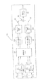
図2は本発明の好適な実施形態に従った合成CDMA信号205を生成する技術200を描写した図である。この好適な実施形態はまた、第1及び第2の複数のデジタルトラフィックチャネル信号Φ1,1...Φ1,NとΦ2,1...Φ2,N各々を符号化し合成して第1の合成同相信号Xi1、第1の合成直交信号Xq1、第2の合成同相信号Xi2、及び第2の合成直交信号Xq2にしているので、この技術は図1に描写された技術と類似している。しかしながら、図1に描写された従来技術とは異なり、合成同相及び直交信号Xi1,Xq1,Xi2及びXq2は、振幅制限をするアプリケーション専用集積回路(ASIC)250へと送られる。
【0022】
ASIC250は合成同相及び直交信号Xi1,Xq1,Xi2及びXq2の振幅を、これらの信号がパルス整形フィルタ120aと120bとに送られる前に制限できる高速のハードウェアデバイスである。ASIC250について以下により詳細に説明する。今やフィルタされ振幅調整がなされた合成同相及び直交信号Xi1とXq1はそれから周波数f1のCDMA搬送波によって変調され、合成されて第1の独立したCDMA信号210を形成する。同様に、今やフィルタされ振幅調整がなされた合成同相及び直交信号Xi2とXq2はそれから周波数f2のCDMA搬送波によって変調され、合成されて第2の独立したCDMA信号215を形成する。それから、2つの独立したCDMA搬送信号210と215とはアップコンバートされ合成されてCDMA信号205を形成する。それから、CDMA信号205の信号電力は送信に先だって高出力アルゴリズムによって大きくされる。
【0023】
本発明の好適な実施形態に従えば、CDMA信号、例えば、CDMA信号205の振幅を制限することはまず、第1の独立したCDMA信号210に関係した最大振幅a1と第2の独立したCDMA信号215に関係した最大振幅a2の決定を必要とする。これらの決定は図3に図示されたシンボル群の図を参照することでより良い理解が得られる。ここで、S1は第1のCDMA信号210に対応した振幅と位相を表し、S2は第2のCDMA信号215に対応した振幅と位相を表している。それから、最大振幅a1とa2とが以下の関係に従って決定される。
【0024】
a1=|S1|=(Xi12+Xq12)1/2 (1)
a2=|S2|=(Xi22+Xq22)1/2 (2)
ここで、Xi1,Xq1,Xi2及びXq2は上述した合成同相及び直交信号の瞬間値を表している。しかしながら、当業者であれば、a1とa2は上述した式(1)と(2)以外の式を用いて近似できることを理解するであろう。
【0025】
いったん、最大振幅a1とa2とが決定されたなら、a1とa2とは伸縮ファクタ“s”を計算するために用いられる。好適な実施形態に従えば、伸縮ファクタ“s”は次の関係によって決定される。
【0026】
s=aclip/a(もし、a>aclip) (3)
s=1 (もし、a≦aclip) (4)
ここで、aclipはパルス整形フィルタ120aと120bの入力で具体化する最大許容振幅値として定義され、“a”は最大全体振幅を表している。即ち、最大全体振幅“a”は以下の関係によって与えられる。
【0027】
a=a1+a2 (5)
それから、伸縮ファクタ“s”は合成同相及び合成直交信号Xi1,Xq1,Xi2及びXq2に関係した瞬間振幅を制限するために用いられる。
【0028】
図4は、より詳細に、上述した好適な振幅制限技術を実行するのに必要なASIC250に関係した機能要素を図示している。即ち、ASIC250は最大振幅計算モジュール405を含んでいる。最大振幅計算モジュール405は、上述の式(1)と(2)とを解くために必要な測定と計算を行うことができる高速デジタル回路を表している。それから、ASIC250はa1とa2とを伸縮ファクタ計算モジュール410へと送る。伸縮ファクタ計算モジュール410は、上述の式(3)、(4)、及び(5)とを解くために必要な計算を実行することができる高速デジタル回路を表している。
【0029】
いったん、伸縮ファクタ“s”が決定されたなら、伸縮ファクタ計算モジュール410はその伸縮ファクタ“s”を伸縮モジュール415aと415bとに送る。伸縮モジュール415aは伸縮ファクタ“s”を合成同相信号Xi1と合成直交信号Xq1とに適用する(例えば、乗算する)ことが可能な高速デジタル回路を表している。同様に、伸縮モジュール415bはその伸縮ファクタ“s”を合成同相信号Xi2と合成直交信号Xq2とに適用することが可能な高速デジタル回路を表している。いったん、同相及び直交信号Xi1,Xq1,Xi2及びXq2が伸縮されたなら、ASIC250はその振幅制限のなされた信号を、図2に図示されているように、パルス整形フィルタ120aと120bとに送る。
【0030】
図5はASIC250の別の実施形態を図示している。この別の実施形態に従えば、別々の伸縮ファクタs1とs2とが伸縮ファクタ計算モジュール510によって計算される。ここで、伸縮ファクタs1は同相及び直交信号Xi1とXq1の瞬間振幅を独立に調整するのに用いられ、伸縮ファクタs2は同相及び直交信号Xi2とXq2の瞬間振幅を独立に調整するのに用いられる。即ち、s1とs2とは次の式に従って決定される。
【0031】
s1=(aclip/a1)*w1 (6)
s2=(aclip/a2)*w2 (7)
ここで、w1とw2とは夫々、独立に伸縮ファクタs1とs2とを調整するための第1及び第2の重み付け因子を表している。
【0032】
図5に図示された別の技術は、図2のCH2のトラフィックチャネル信号に関係した信号電力レベル間に比較して、CH1のトラフィックチャネル信号に関係した信号電力レベル間にかなりの不均衡があるときに、採用されると良い。例えば、CH1のトラフィックチャネル信号に関係した信号電力レベルがCH2のトラフィックチャネル信号に関係した信号電力レベルよりもかなり小さいなら、合成同相及び直交信号Xi2とXq2についての瞬間振幅だけを伸縮することが適切であるかもしれない。これは、重み付け因子w2に値“1”を設定し、重み付け因子w1をs1が値“1”に近似するように設定することにより、効果的に成し遂げられる。もちろん、合成同相及び直交信号Xi1,Xq1,Xi2及びXq2についての瞬間振幅を伸縮することが適切であると思われる任意の値に重み付け因子w1とw2とは設定されることが理解されるであろう。
【0033】
更に別の実施形態に従えば、合成同相及び直交信号のサンプル(例えば、Xi1,Xq1,Xi2及びXq2)に関連した瞬間振幅のサンプルは、もし振幅サンプルが所定の最大値を越えるなら、制限されたり、クリップされても良い。合成CDMA信号の平均電力レベルの対応する低下と、それゆえに、その合成CDMA信号のPRPTAの望まれない増大とを防ぐために、この別の実施形態では1つ以上の以降に続く合成同相及び直交信号サンプルの振幅を増加させるために用いられる伸縮ファクタを生成する。ここで、1つ以上の以降に続くサンプルにわたる振幅増加は以前にクリップされたサンプルの振幅の減少に比例する。もちろん、これら以降に続くサンプルの振幅を調整することにより、以前にクリップされたサンプルの瞬間振幅を補償する。その上、当業者であれば、動的に1個の以降に続くサンプルの振幅を増加させるよりもむしろ、いくつかの以降に続く合成同相及び直交信号サンプルの振幅を適度に増幅することにより、より低いビットエラー率が達成されることを認識するであろう。このことは、1個の以降に続くサンプルの振幅を増加させることが前述した所定の最大値を超える振幅になる結果となる場合に、特に、真実である。
【0034】
図6は2つのシンボル群の図605と610とを図示している。シンボル群の図605は、本発明の好適な実施形態に従うデジタル振幅制限が採用されたときのCDMA信号(例えば、CDMA信号205)に関係したシンボル(即ち、瞬間振幅)の位置を示している。シンボル群の図610は、デジタル振幅制限が採用されていないときのCDMA信号に関係したシンボルの位置を示している。当業者であれば即座に認識することであるが、デジタル振幅制限が採用されるときaclipでその半径が定義される円形の領域内に送信されるシンボルは全て位置する。しかしながら、デジタル振幅制限が採用されないとき、この円形領域内に送信されるシンボル全て必ずしも位置する訳ではない。後者の場合はたぶん大きなピーク対平均電力の比となる結果となり、上述したように、高出力アンプの効率は悪い。
【0035】
本発明はいくつかの代表的な実施形態に関して説明した。しかしながら、当業者には、本発明を上述した代表的な実施形態以外の特定の形に具体化することが可能であることがすぐに明らかであろう。このことは本発明の精神を逸脱することなくなされる。これら代表的な実施形態はただ説明のためだけのものであり、これによっていか様にも制限されるとは考えるべきではない。本発明の範囲は前述の説明ではなく、添付した請求の範囲によって与えられており、請求の範囲の中にある全ての変形例や同等物はそこに包含されることが意図されている。
【図面の簡単な説明】
本発明の目的や利点は図面と関連して詳細な説明を読むことにより理解されるが、その図面は次の通りである。
【図1】 従来例に従うCDMA信号を生成し増幅する技術を示している。
【図2】 本発明の好適な実施形態に従うCDMA信号を生成し増幅する技術を示している。
【図3】 シンボル群の図である。
【図4】 本発明の好適な実施形態に従う増幅制限ASICを図示している。
【図5】 本発明の別の実施形態に従う増幅制限ASICを図示している。
【図6】 シンボル群の図である。[0001]
BACKGROUND The present invention relates to a cellular radio communication system, and more particularly to a cellular radio communication system employing a code division multiple access (CDMA) scheme.
[0002]
Cellular radio communication systems employ one or more channel access schemes. One well-known channel access scheme is the code division multiple access (CDMA) scheme. CDMA is a known technique. Unlike other channel access schemes (eg, time division or frequency division multiple access), many different traffic channel signals are transmitted simultaneously, overlapping in both the time domain and the frequency domain.
[0003]
In order to distinguish each traffic channel signal from other traffic channel signals, each traffic channel signal is encoded with one or more unique spreading codes, as is well known in the art. By modulating each traffic channel signal with a spreading code, the sampling rate (ie, “chip rate”) may increase substantially according to the spreading factor. For example, each traffic channel signal is modulated according to a digital modulation scheme such as, for example, quadrature amplitude modulation (QAM) or phase shift keying (PSK) techniques. As a result, in-phase and quadrature component signals are generated for each traffic channel signal. QAM and PSK are known techniques. The in-phase and quadrature component signals associated with each traffic channel are then encoded using a unique spreading code sequence. The resulting in-phase and quadrature component signal pairs are sampled (ie, at the chip rate) and individually weighted. The in-phase and quadrature component signals are eventually combined to form a combined in-phase signal and a combined quadrature signal. Then, the combined in-phase signal and the combined quadrature signal are separately filtered by a low pass and pulse shaping filter. Following filtering, the combined in-phase signal and combined quadrature signal are respectively modulated by a cosine carrier and a sine carrier and combined into a single multicode CDMA signal. The single multicode CDMA signal is then upconverted by the carrier frequency and the signal power associated with the CDMA signal is increased by the high power amplifier prior to transmission. In the receiver, a baseband signal related to each traffic channel signal is extracted from the CDMA signal by demodulating and decoding the CDMA signal using the carrier frequency and various spreading codes. Further, in a typical cellular communication system, it is understood that the transmission source may be, for example, a high power base station, and the receiving entity may be, for example, a mobile station (ie, a mobile phone). ing.
[0004]
It is often preferred to generate more than one CDMA signal, especially when there are a large number of traffic channel signals. Here, each of the two or more CDMA signals is up-converted by its own unique CDMA carrier frequency. These two or more upconverted CDMA signals are then amplified independently by a corresponding high power amplifier prior to transmission. Alternatively, two or more upconverted CDMA signals are combined into a single CDMA signal, which is then amplified by a single high power amplifier prior to transmission.
[0005]
As will be readily appreciated by those skilled in the art, CDMA substantially increases system bandwidth, which in turn adds to the overall network traffic handling capability. In addition, as described above, combining independent CDMA signals into a single CDMA signal does not require a separate high power amplifier for each independent CDMA signal, but rather a single high power up. It is advantageous because it is only needed. This is advantageous because high-power amplifiers are expensive, and employing one high-power amplifier instead of multiple amplifiers results in substantial cost savings.
[0006]
Despite the advantages associated with CDMA, combining multiple traffic channel signals and / or independent CDMA signals generally significantly increases the peak-to-average power ratio associated with the resulting CDMA signal. To do. That is, the peak to average power ratio for a CDMA signal is determined according to the following relationship:
[0007]
PR PTA = PR F + 10 * log (N)
Here, PR PTA represents the ratio of the peak-to-average power of the corresponding combined signal, PR F represents the power ratio of the low pass and pulse shaping filter, and N represents the number of traffic channels that make up the CDMA signal.
[0008]
A problem related to the large peak-to-average power ratio is that this reduces the efficiency of the high power amplifier in the transmitter. As will be readily appreciated by those skilled in the art, efficiency is measured by the amount of output power (ie, Pmean) divided by the amount of input power (ie, Pdc + Ppeak). As Ppeak (ie peak power) increases relative to Pmean, the efficiency of the high power amplifier decreases.
[0009]
One possible solution is simply to limit or clip the amplitude (ie, Ppeak) of the CDMA signal. Unfortunately, this will probably result in intermodulation products or / and spectral distortion. Secondly, intermodulation products or / and spectral distortions will likely cause interference between the various traffic channel signals. This is therefore not a preferred solution.
[0010]
Another possible solution is to design a more complex high power amplifier. The amplifier allows a CDMA signal exhibiting a large peak-to-average ratio and can be amplified more efficiently. However, since the cost of a high power amplifier is generally proportional to its complexity, this is also not a suitable solution. Therefore, using this solution would result in an increase in the cost of the communication device that houses the high power amplifier.
[0011]
(“Miller et al.”), US Pat. No. 5,621,762, presents yet another possible solution to the peak-to-average power ratio problem, according to which it will be transmitted shortly Before the communication signal to be filtered is filtered and then amplified, it limits the ratio of peak to average power. That is, Miller describes a peak power suppression device that reduces the peak-to-average power ratio of a single code sequence at the input of a high power amplifier. The peak power suppression device receives a single code sequence, maps the code sequence onto a diagram of symbols, predicts the expected response from the pulse shaping filter, and follows the expected response of the pulse shaping filter A digital signal processor (DSP) is used to limit the amplitude appearing on the symbol group diagram.
[0012]
The first problem associated with the solution presented by Miller is that the peak power suppression device is designed for application in fields where it is not CDMA. Therefore, the peak power suppression devices described herein address specific characteristics related to CDMA such as high data bit rates, multiple traffic channel signals and / or multicode sequences, and multiple CDMA carrier signals. I can't. For example, the peak power suppression device described by Miller is evidenced by the fact that it employs a DSP and the fact that the DSP has the time required to perform a pulse shaping filter prediction algorithm. As is inherently slow. Therefore, it can limit the peak-to-average power ratio of the communication signal before it is filtered and then amplified, and can process fairly fast data bit rates, multiple code sequences, and multiple CDMA carrier signals A communication signal amplitude limiting device is required.
[0013]
Summary In view of the problems identified above, the object of the present invention is to efficiently reduce the peak-to-average power ratio for a CDMA signal so that the efficiency of the high-power amplifier of the transmitter does not drop. Is to provide the ability to do.
[0014]
Another object of the present invention is to reduce the peak-to-average power ratio for a CDMA signal without creating intermodulation products and / or spectral distortions.
[0015]
Yet another object of the present invention is to limit the peak to average power ratio for a CDMA signal when there are two or more independent CDMA carrier signals.
[0016]
In accordance with one aspect of the present invention, the above and other objects are achieved by a method and / or apparatus for limiting the amplitude of complex code division multiple access (CDMA) signals. The method and / or apparatus comprises means for measuring the instantaneous amplitude for each of a plurality of digitally encoded sequences and means for generating a maximum amplitude as a function of the measurement of the instantaneous amplitude. The method and / or apparatus also includes means for deriving an amplitude scaling factor as a function of the maximum amplitude and means for applying the amplitude scaling factor to each of the plurality of digitally encoded sequences. The amplitude is then limited and a CDMA signal is generated based on each digitally encoded sequence.
[0017]
According to another aspect of the invention, the foregoing and other objects are achieved by a method and / or apparatus for limiting the peak-to-average power ratio of complex code division multiple access (CDMA) signals. The method and / or apparatus according to this other aspect of the invention comprises means for measuring the instantaneous amplitudes for the first and second combined in-phase signals and the first and second combined quadrature signals. Here, the first and second combined in-phase signals and the first and second combined quadrature signals are functions of the first and second sets of digitally encoded traffic channel signals. The method and / or apparatus also includes the first and second combined in-phase signals and the first as a function of the instantaneous amplitude measured in relation to the first and second combined in-phase signals and the quadrature signal. And means for generating an amplitude scaling factor for the second composite quadrature signal. Once the amplitude scaling factors for the first and second combined in-phase signals and the first and second combined quadrature signals have been generated, the method and / or apparatus can perform the first and second combined signals. Means for applying the expansion and contraction factors of the amplitudes of the first and second combined in-phase signals and the first and second combined quadrature signals to the phase signal and the first and second combined quadrature signals are used. A CDMA signal is then generated based on the first and second in-phase and quadrature signals.
[0018]
DETAILED DESCRIPTION Various features of the present invention will be described with reference to the drawings, in which like elements are identified with the same reference symbols.
[0019]
FIG. 1 is a diagram depicting a conventional technique for generating a CDMA signal 105. As shown, CDMA signal 105 is generated by combining two (or more) independent CDMA signals 110 and 115. According to this prior art, a first set of digital traffic channel signals Φ1,1,. . . Each traffic channel signal from Φ1, N and a second set of digital traffic channel signals Φ2,1. . . Each traffic channel signal from Φ2, N is modulated using quadrature amplitude modulation (QAM) techniques. This results in in-phase and quadrature signal pairs for each traffic channel signal. Then, each in-phase signal related to the first set of traffic channel signals is encoded using a unique spreading code, individually weighted, and combined with the other in-phase signals, thereby generating the first combination. In-phase signal Xi1 is generated and each quadrature signal related to the first set of traffic channel signals is similarly encoded, weighted and combined, thereby generating a first combined quadrature signal Xq1. Similarly, each in-phase signal related to the second set of traffic channel signals is encoded, weighted and combined, thereby generating a second combined in-phase signal X i2, Each quadrature signal related to the traffic channel signal is similarly encoded, weighted and combined, thereby generating a second combined quadrature signal Xq2. As shown in FIG. 1, the first combined in-phase signal Xi1 and the first combined quadrature signal Xq1 are then sent to the first pulse shaping filter 120a. Similarly, the second combined in-phase signal Xi2 and the second combined quadrature signal Xq2 are sent to the second pulse shaping filter 120b. The filtered signal is then sent to first and second vector modulators 125a and 125b. First vector modulator 125a modulates the composite in-phase signal Xi1 by a cosine carrier frequency f 1, also modulates the synthesis quadrature signal Xq1 by sine carrier frequency f 1. The vector modulator 125a then modulates the modulated combined in-phase signal Xi1 with the modulated combined quadrature signal Xq1, thereby generating a first independent CDMA signal 110. At the same time, the second vector modulator 125b modulates the composite in-phase signal Xi2 by a cosine carrier frequency f 2, also modulates the synthesis quadrature signal Xq2 by sine carrier frequency f 2. The vector modulator 125a then modulates the modulated composite in-phase signal Xi2 with the modulated composite quadrature signal Xq2, thereby generating a second independent CDMA signal 115. The two independent CDMA signals 110 and 115 are then combined to form the CDMA signal 105 which is then sent to the high power amplifier 130 prior to transmission.
[0020]
As described above, the peak-to-average power ratio associated with the CDMA signal 105 increases as the number of traffic channel signals Φ increases, and then the efficiency of the high-power amplifier 130 increases as the peak-to-average power ratio increases. descend. Further, if an attempt is made to limit or clip the amplitude of the CDMA signal 105 at the high power amplifier 130 or a transmitter (not shown) that houses the high power amplifier 130, a significant amount of intermodulation and / or As a result, spectral distortion occurs.
[0021]
FIG. 2 depicts a technique 200 for generating a combined CDMA signal 205 in accordance with a preferred embodiment of the present invention. This preferred embodiment also includes first and second plurality of digital traffic channel signals Φ1,1,. . . Φ1, N and Φ2,1. . . Since each of Φ2, N is encoded and combined into a first combined in-phase signal Xi1, a first combined quadrature signal Xq1, a second combined in-phase signal Xi2, and a second combined quadrature signal Xq2, The technique is similar to the technique depicted in FIG. However, unlike the prior art depicted in FIG. 1, the combined in-phase and quadrature signals Xi1, Xq1, Xi2 and Xq2 are sent to an application specific integrated circuit (ASIC) 250 that provides amplitude limiting.
[0022]
The
[0023]
In accordance with a preferred embodiment of the present invention, limiting the amplitude of a CDMA signal, eg, CDMA signal 205, first includes a maximum amplitude a1 associated with a first independent CDMA signal 210 and a second independent CDMA signal. The determination of the maximum amplitude a2 related to 215 is required. These decisions can be better understood with reference to the symbol group diagram shown in FIG. Here, S1 represents the amplitude and phase corresponding to the first CDMA signal 210, and S2 represents the amplitude and phase corresponding to the second CDMA signal 215. Then, the maximum amplitudes a1 and a2 are determined according to the following relationship.
[0024]
a1 = | S1 | = (
a2 = | S2 | = (Xi2 2 + Xq2 2 ) 1/2 (2)
Here, Xi1, Xq1, Xi2 and Xq2 represent the instantaneous values of the above-mentioned combined in-phase and quadrature signals. However, those skilled in the art will appreciate that a1 and a2 can be approximated using equations other than equations (1) and (2) described above.
[0025]
Once the maximum amplitudes a1 and a2 are determined, a1 and a2 are used to calculate the scaling factor “s”. According to a preferred embodiment, the scaling factor “s” is determined by the relationship:
[0026]
s = a clip / a (if a> a clip ) (3)
s = 1 (If a ≦ a clip ) (4)
Here, a clip is defined as the maximum allowable amplitude value embodied by the inputs of the pulse shaping filters 120a and 120b, and “a” represents the maximum overall amplitude. That is, the maximum overall amplitude “a” is given by the following relationship.
[0027]
a = a1 + a2 (5)
The expansion factor "s" is then used to limit the instantaneous amplitude associated with the combined in-phase and combined quadrature signals Xi1, Xq1, Xi2 and Xq2.
[0028]
FIG. 4 illustrates in more detail the functional elements associated with the
[0029]
Once the expansion factor “s” has been determined, the expansion factor calculation module 410 sends the expansion factor “s” to the
[0030]
FIG. 5 illustrates another embodiment of the
[0031]
s1 = (a clip / a1) * w1 (6)
s2 = (a clip / a2) * w2 (7)
Here, w1 and w2 represent first and second weighting factors for independently adjusting the expansion / contraction factors s1 and s2, respectively.
[0032]
Another technique illustrated in FIG. 5 has a significant imbalance between the signal power levels associated with the CH1 traffic channel signal compared to the signal power levels associated with the CH2 traffic channel signal of FIG. Sometimes it should be adopted. For example, if the signal power level associated with the CH1 traffic channel signal is significantly less than the signal power level associated with the CH2 traffic channel signal, it is appropriate to scale only the instantaneous amplitudes for the combined in-phase and quadrature signals Xi2 and Xq2. May be. This is effectively accomplished by setting the weighting factor w2 to a value “1” and setting the weighting factor w1 so that s1 approximates the value “1”. Of course, it will be understood that the weighting factors w1 and w2 are set to arbitrary values that may be appropriate to scale the instantaneous amplitude for the combined in-phase and quadrature signals Xi1, Xq1, Xi2 and Xq2. Let's go.
[0033]
According to yet another embodiment, instantaneous amplitude samples associated with composite in-phase and quadrature signal samples (eg, Xi1, Xq1, Xi2, and Xq2) are limited if the amplitude samples exceed a predetermined maximum value. Or clipped. In order to prevent a corresponding decrease in the average power level of the combined CDMA signal and, therefore, an undesired increase in the PR PTA of the combined CDMA signal, in this alternative embodiment one or more subsequent combined in-phase and quadrature Generate a scaling factor that is used to increase the amplitude of the signal samples. Here, the increase in amplitude over one or more subsequent samples is proportional to the decrease in the amplitude of the previously clipped sample. Of course, by adjusting the amplitude of these subsequent samples, the instantaneous amplitude of the previously clipped sample is compensated. Moreover, those skilled in the art will appropriately amplify the amplitude of several subsequent composite in-phase and quadrature signal samples, rather than dynamically increasing the amplitude of one subsequent sample, It will be appreciated that a lower bit error rate is achieved. This is particularly true when increasing the amplitude of one subsequent sample results in an amplitude that exceeds the predetermined maximum value described above.
[0034]
FIG. 6 illustrates two symbol groups, FIGS. 605 and 610. Symbol group diagram 605 shows the position of a symbol (ie, instantaneous amplitude) relative to a CDMA signal (eg, CDMA signal 205) when digital amplitude limiting is employed in accordance with a preferred embodiment of the present invention. Symbol group FIG. 610 shows the position of the symbol relative to the CDMA signal when digital amplitude limiting is not employed. One skilled in the art will recognize immediately that when a digital amplitude limit is employed, all symbols transmitted within a circular region whose radius is defined by a clip are located. However, not all transmitted symbols are necessarily located within this circular region when digital amplitude limiting is not employed. The latter case probably results in a large peak-to-average power ratio, and as described above, the efficiency of the high power amplifier is poor.
[0035]
The invention has been described with reference to several representative embodiments. However, it will be readily apparent to those skilled in the art that the present invention may be embodied in specific forms other than the exemplary embodiments described above. This is done without departing from the spirit of the invention. These exemplary embodiments are for illustration only and should not be considered limiting in any way. The scope of the present invention is given by the appended claims rather than by the foregoing description, and all modifications and equivalents falling within the scope of the claims are intended to be embraced therein.
[Brief description of the drawings]
The objects and advantages of the present invention will be understood by reading the detailed description in conjunction with the drawings, in which:
FIG. 1 shows a technique for generating and amplifying a CDMA signal according to a conventional example.
FIG. 2 illustrates a technique for generating and amplifying a CDMA signal according to a preferred embodiment of the present invention.
FIG. 3 is a diagram of a symbol group.
FIG. 4 illustrates an amplification limited ASIC according to a preferred embodiment of the present invention.
FIG. 5 illustrates an amplification limited ASIC according to another embodiment of the present invention.
FIG. 6 is a diagram of a symbol group.
Claims (14)
第1のセットのデジタル的に符号化されたトラフィックチャネル信号の関数である第1の合成同相信号と第1の合成直交信号とについての瞬間振幅を測定する手段と、
第2のセットのデジタル的に符号化されたトラフィックチャネル信号の関数である第2の合成同相信号と第2の合成直交信号とについての瞬間振幅を測定する手段と、
前記第1の合成同相及び直交信号と前記第2の合成同相及び直交信号とに関係して測定された前記瞬間振幅の関数として、前記第1の合成同相信号と前記第1の合成直交信号についての振幅の伸縮ファクタを生成する手段と、
前記第1の合成同相及び直交信号と前記第2の合成同相及び直交信号とに関係して測定された前記瞬間振幅の関数として、前記第2の合成同相信号と前記第2の合成直交信号についての振幅の伸縮ファクタを生成する手段と、
前記第1の合成同相信号と前記第1の合成直交信号に、前記第1の合成同相信号と前記第1の合成直交信号についての前記振幅の伸縮ファクタを適用する手段と、
前記第2の合成同相信号と前記第2の合成直交信号に、前記第2の合成同相信号と前記第2の合成直交信号についての前記振幅の伸縮ファクタを適用する手段と、
前記第1及び第2の同相及び直交信号に基づいて、CDMA信号を生成する手段と、
前記第1の合成同相信号と前記第1の合成直交信号について生成された振幅の伸縮ファクタに第1の重みファクタを適用する手段と、
前記第2の合成同相信号と前記第2の合成直交信号について生成された振幅の伸縮ファクタに第2の重みファクタを適用する手段と、
前記第1の合成同相信号と前記第1の合成直交信号について生成された振幅の伸縮ファクタが前記第1のセットのデジタル的に符号化されたトラフィックチャネル信号を表現する信号電力レベルの関数であるように前記第1の重みファクタを調整する手段と、
前記第1の重みファクタを調整する手段とは独立に、前記第2の合成同相信号と前記第2の合成直交信号について生成された振幅の伸縮ファクタが前記第2のセットのデジタル的に符号化されたトラフィックチャネル信号を表現する信号電力レベルの関数であるように前記第2の重みファクタを調整する手段とを有することを特徴とする装置。An apparatus for limiting a peak to average power ratio of a complex code division multiple access (CDMA) signal, comprising:
Means for measuring an instantaneous amplitude for a first composite in-phase signal and a first composite quadrature signal that are a function of a first set of digitally encoded traffic channel signals;
Means for measuring an instantaneous amplitude for a second combined in-phase signal and a second combined quadrature signal that are a function of a second set of digitally encoded traffic channel signals;
The first combined in-phase signal and the first combined quadrature signal as a function of the instantaneous amplitude measured in relation to the first combined in-phase and quadrature signal and the second combined in-phase and quadrature signal. Means for generating an amplitude scaling factor for
The second combined in-phase signal and the second combined quadrature signal as a function of the instantaneous amplitude measured in relation to the first combined in-phase and quadrature signal and the second combined in-phase and quadrature signal. Means for generating an amplitude scaling factor for
Means for applying the amplitude expansion factor for the first combined in-phase signal and the first combined quadrature signal to the first combined in-phase signal and the first combined quadrature signal;
Means for applying the amplitude scaling factor for the second combined in-phase signal and the second combined quadrature signal to the second combined in-phase signal and the second combined quadrature signal;
Means for generating a CDMA signal based on the first and second in-phase and quadrature signals;
Means for applying a first weighting factor to an amplitude scaling factor generated for the first combined in-phase signal and the first combined quadrature signal;
Means for applying a second weighting factor to the amplitude scaling factor generated for the second combined in-phase signal and the second combined quadrature signal;
The amplitude scaling factor generated for the first combined in-phase signal and the first combined quadrature signal is a function of the signal power level representing the first set of digitally encoded traffic channel signals. Means for adjusting the first weight factor to be,
Independently of the means for adjusting the first weight factor, the amplitude scaling factor generated for the second combined in-phase signal and the second combined quadrature signal is digitally encoded in the second set. And means for adjusting the second weight factor to be a function of signal power level representative of the normalized traffic channel signal.
前記第1の合成同相信号と前記第1の合成直交信号についての振幅の伸縮ファクタを生成する手段と、前記第2の合成同相信号と前記第2の合成直交信号についての振幅の伸縮ファクタを生成する手段とは、前記最大振幅の関数として前記振幅の伸縮ファクタを生成する手段を含むことを特徴とする請求項1に記載の装置。Means for generating a maximum amplitude as a function of the instantaneous amplitude measured in relation to the first composite and the second composite in-phase and quadrature signals;
Means for generating an amplitude scaling factor for the first synthesized in-phase signal and the first synthesized quadrature signal; and an amplitude scaling factor for the second synthesized in-phase signal and the second synthesized quadrature signal. the means for generating, according to claim 1, characterized in that it comprises a means for generating a stretch factor of the amplitude as a function of the maximum amplitude.
前記1つ以上の合成同相及び合成直交信号のサンプルの振幅は、以前の合成同相及び合成直交信号のサンプルの振幅における対応する減少を補償するために増加されることを特徴とする請求項1に記載の装置。Means for maintaining the average power of the CDMA signal by applying an amplitude scaling factor to one or more samples of the combined in-phase and combined quadrature signals;
The amplitude of samples of the one or more synthetic phase and combining quadrature signals to claim 1, characterized in that it is increased to compensate for the corresponding decrease in the amplitude of the samples of the previous synthesis phase and combining the quadrature signal The device described.
前記第2の合成同相信号と前記第2の合成直交信号をフィルタする手段と、
前記フィルタされた、第1の合成同相信号を第1のコサイン搬送波によって、前記フィルタされた、第1の合成直交信号を前記第1のコサイン搬送波と同じ周波数をもつ第1のサイン搬送波によって変調する手段と、
前記フィルタされた、第2の合成同相信号を第2のコサイン搬送波によって、前記フィルタされた、第2の合成直交信号を前記第2のコサイン搬送波と同じ周波数をもつ第2のサイン搬送波によって変調する手段と、
前記第1のフィルタされた、合成同相信号に、前記第1のフィルタされた、合成直交信号を合成して、第1の独立なCDMA信号を生成する手段と、
前記第2のフィルタされた、合成同相信号に、前記第2のフィルタされた、合成直交信号を合成して、第2の独立なCDMA信号を生成する手段と、
前記第1の独立したCDMA信号を第1のCDMA搬送周波数を用いてアップコンバートする手段と、
前記第2の独立したCDMA信号を第2のCDMA搬送周波数を用いてアップコンバートする手段とをさらに有することを特徴とする請求項1に記載の装置。Means for filtering the first combined in-phase signal and the first combined quadrature signal;
Means for filtering the second combined in-phase signal and the second combined quadrature signal;
The filtered first synthesized in-phase signal is modulated by a first cosine carrier, and the filtered first synthesized quadrature signal is modulated by a first sine carrier having the same frequency as the first cosine carrier. Means to
The filtered second synthesized in-phase signal is modulated by a second cosine carrier, and the filtered second synthesized quadrature signal is modulated by a second sine carrier having the same frequency as the second cosine carrier. Means to
Means for combining the first filtered combined in-phase signal with the first filtered combined quadrature signal to generate a first independent CDMA signal;
Means for combining the second filtered combined in-phase signal with the second filtered combined quadrature signal to generate a second independent CDMA signal;
Means for upconverting said first independent CDMA signal using a first CDMA carrier frequency;
The apparatus of claim 1 , further comprising means for upconverting the second independent CDMA signal using a second CDMA carrier frequency.
前記第1の独立したCDMA信号と前記第2の独立したCDMA信号とを合成する手段を有することを特徴とする請求項6に記載の装置。The means for generating the CDMA signal is:
The apparatus of claim 6 , comprising means for combining the first independent CDMA signal and the second independent CDMA signal.
第1のセットのデジタル的に符号化されたトラフィックチャネル信号の関数である第1の合成同相信号と第1の合成直交信号とについての瞬間振幅を測定する工程と、
第2のセットのデジタル的に符号化されたトラフィックチャネル信号の関数である第2の合成同相信号と第2の合成直交信号とについての瞬間振幅を測定する工程と、
前記第1の合成同相及び直交信号と前記第2の合成同相及び直交信号とに関係して測定された前記瞬間振幅の関数として、前記第1の合成同相信号と前記第1の合成直交信号についての振幅の伸縮ファクタを生成する工程と、
前記第1の合成同相及び直交信号と前記第2の合成同相及び直交信号とに関係して測定された前記瞬間振幅の関数として、前記第2の合成同相信号と前記第2の合成直交信号についての振幅の伸縮ファクタを生成する工程と、
前記第1の合成同相信号と前記第1の合成直交信号に、前記第1の合成同相信号と前記第1の合成直交信号についての前記振幅の伸縮ファクタを適用する工程と、
前記第2の合成同相信号と前記第2の合成直交信号に、前記第2の合成同相信号と前記第2の合成直交信号についての前記振幅の伸縮ファクタを適用する工程と、
前記第1及び第2の同相及び直交信号に基づいて、CDMA信号を生成する工程と、
前記第1の合成同相信号と前記第1の合成直交信号について生成された振幅の伸縮ファクタに第1の重みファクタを適用する工程と、
前記第2の合成同相信号と前記第2の合成直交信号について生成された振幅の伸縮ファクタに第2の重みファクタを適用する工程と、
前記第1の合成同相信号と前記第1の合成直交信号について生成された前記振幅の伸縮ファクタが前記第1のセットのデジタル的に符号化されたトラフィックチャネル信号を表現する信号電力レベルの関数であるように前記第1の重みファクタを調整する工程と、
前記第1の重みファクタを調整する工程とは独立に、前記第2の合成同相信号と前記第2の合成直交信号について生成された前記振幅の伸縮ファクタが前記第2のセットのデジタル的に符号化されたトラフィックチャネル信号を表現する信号電力レベルの関数であるように前記第2の重みファクタを調整する工程とを有することを特徴とする方法。A method for limiting the peak to average power ratio of a complex code division multiple access (CDMA) signal, comprising:
Measuring an instantaneous amplitude for a first synthesized in-phase signal and a first synthesized quadrature signal that are a function of a first set of digitally encoded traffic channel signals;
Measuring an instantaneous amplitude for a second combined in-phase signal and a second combined quadrature signal that are a function of a second set of digitally encoded traffic channel signals;
The first combined in-phase signal and the first combined quadrature signal as a function of the instantaneous amplitude measured in relation to the first combined in-phase and quadrature signal and the second combined in-phase and quadrature signal. Generating an amplitude scaling factor for
The second combined in-phase signal and the second combined quadrature signal as a function of the instantaneous amplitude measured in relation to the first combined in-phase and quadrature signal and the second combined in-phase and quadrature signal. Generating an amplitude scaling factor for
Applying the amplitude scaling factor for the first combined in-phase signal and the first combined quadrature signal to the first combined in-phase signal and the first combined quadrature signal;
Applying the amplitude scaling factor for the second combined in-phase signal and the second combined quadrature signal to the second combined in-phase signal and the second combined quadrature signal;
Generating a CDMA signal based on the first and second in-phase and quadrature signals;
Applying a first weighting factor to the amplitude scaling factor generated for the first combined in-phase signal and the first combined quadrature signal;
Applying a second weighting factor to the amplitude scaling factor generated for the second combined in-phase signal and the second combined quadrature signal;
A function of signal power level in which the amplitude scaling factor generated for the first combined in-phase signal and the first combined quadrature signal represents the first set of digitally encoded traffic channel signals. Adjusting the first weighting factor to be
Independently of adjusting the first weighting factor, the amplitude scaling factor generated for the second combined in-phase signal and the second combined quadrature signal is digitally converted into the second set. Adjusting the second weight factor to be a function of the signal power level representing the encoded traffic channel signal.
前記第1の合成同相信号と前記第1の合成直交信号についての振幅の伸縮ファクタと、前記第2の合成同相信号と前記第2の合成直交信号についての振幅の伸縮ファクタとは、前記最大振幅の関数としても生成されることを特徴とする請求項8に記載の方法。Generating a maximum amplitude as a function of the instantaneous amplitude measured in relation to the first synthesized and the second synthesized in-phase and quadrature signals;
The amplitude expansion / contraction factor for the first combined in-phase signal and the first combined quadrature signal, and the amplitude expansion / contraction factor for the second combined in-phase signal and the second combined quadrature signal are: 9. The method of claim 8 , wherein the method is also generated as a function of maximum amplitude.
前記1つ以上の合成同相及び合成直交信号のサンプルの振幅は、以前の合成同相及び合成直交信号のサンプルの振幅における対応する減少を補償するために増加されることを特徴とする請求項8に記載の方法。Maintaining the average power of the CDMA signal by applying the amplitude scaling factor to samples of one or more combined in-phase and combined quadrature signals;
The amplitude of samples of the one or more synthetic phase and combining quadrature signals to claim 8, characterized in that it is increased to compensate for the corresponding reduction in the amplitude of the samples of the previous synthesis phase and combining the quadrature signal The method described.
前記第2の合成同相信号と前記第2の合成直交信号をフィルタする工程と、
前記フィルタされた、第1の合成同相信号を第1のコサイン搬送波によって、前記フィルタされた、第1の合成直交信号を前記第1のコサイン搬送波と同じ周波数をもつ第1のサイン搬送波によって変調する工程と、
前記フィルタされた、第2の合成同相信号を第2のコサイン搬送波によって、前記フィルタされた、第2の合成直交信号を前記第2のコサイン搬送波と同じ周波数をもつ第2のサイン搬送波によって変調する工程と、
前記第1のフィルタされた、合成同相信号に、前記第1のフィルタされた、合成直交信号を合成して、第1の独立なCDMA信号を生成する工程と、
前記第2のフィルタされた、合成同相信号に、前記第2のフィルタされた、合成直交信号を合成して、第2の独立なCDMA信号を生成する工程と、
前記第1の独立したCDMA信号を第1のCDMA搬送周波数を用いてアップコンバートする工程と、
前記第2の独立したCDMA信号を第2のCDMA搬送周波数を用いてアップコンバートする工程とをさらに有することを特徴とする請求項8に記載の方法。Filtering the first combined in-phase signal and the first combined quadrature signal;
Filtering the second combined in-phase signal and the second combined quadrature signal;
The filtered first synthesized in-phase signal is modulated by a first cosine carrier, and the filtered first synthesized quadrature signal is modulated by a first sine carrier having the same frequency as the first cosine carrier. And a process of
The filtered second synthesized in-phase signal is modulated by a second cosine carrier, and the filtered second synthesized quadrature signal is modulated by a second sine carrier having the same frequency as the second cosine carrier. And a process of
Combining the first filtered combined in-phase signal with the first filtered combined quadrature signal to generate a first independent CDMA signal;
Combining the second filtered combined in-phase signal with the second filtered combined quadrature signal to generate a second independent CDMA signal;
Up-converting the first independent CDMA signal using a first CDMA carrier frequency;
9. The method of claim 8 , further comprising: upconverting the second independent CDMA signal using a second CDMA carrier frequency.
前記第1の独立したCDMA信号と前記第2の独立したCDMA信号とを合成する工程を有することを特徴とする請求項13に記載の方法。The step of generating the CDMA signal includes:
14. The method of claim 13 , comprising combining the first independent CDMA signal and the second independent CDMA signal.
Applications Claiming Priority (3)
| Application Number | Priority Date | Filing Date | Title |
|---|---|---|---|
| US09/056,651 | 1998-04-08 | ||
| US09/056,651 US6266320B1 (en) | 1998-04-08 | 1998-04-08 | Amplitude limitation in CDMA system |
| PCT/SE1999/000490 WO1999053625A1 (en) | 1998-04-08 | 1999-03-26 | Amplitude limitation in a cdma system |
Publications (2)
| Publication Number | Publication Date |
|---|---|
| JP2002511697A JP2002511697A (en) | 2002-04-16 |
| JP4298167B2 true JP4298167B2 (en) | 2009-07-15 |
Family
ID=22005793
Family Applications (1)
| Application Number | Title | Priority Date | Filing Date |
|---|---|---|---|
| JP2000544072A Expired - Lifetime JP4298167B2 (en) | 1998-04-08 | 1999-03-26 | Amplitude limitations in CDMA systems |
Country Status (11)
| Country | Link |
|---|---|
| US (1) | US6266320B1 (en) |
| EP (1) | EP1068673B1 (en) |
| JP (1) | JP4298167B2 (en) |
| KR (1) | KR100605440B1 (en) |
| CN (1) | CN1135724C (en) |
| AR (1) | AR014827A1 (en) |
| AU (1) | AU753700B2 (en) |
| CA (1) | CA2328167C (en) |
| DE (1) | DE69934105T2 (en) |
| TW (1) | TW429692B (en) |
| WO (1) | WO1999053625A1 (en) |
Families Citing this family (23)
| Publication number | Priority date | Publication date | Assignee | Title |
|---|---|---|---|---|
| EP0940925A1 (en) * | 1998-03-05 | 1999-09-08 | Lucent Technologies Inc. | System and method to reduce the peak-to-average power ratio in a DS-CMDA transmitter |
| DE19824233B4 (en) * | 1998-05-29 | 2005-10-06 | Telefonaktiebolaget Lm Ericsson (Publ) | amplitude limiting |
| SE513863C2 (en) * | 1999-01-29 | 2000-11-20 | Ericsson Telefon Ab L M | Method and apparatus for cutting in a CDMA system |
| JP4224168B2 (en) * | 1999-04-23 | 2009-02-12 | パナソニック株式会社 | Base station apparatus and peak power suppression method |
| JP2000349640A (en) * | 1999-06-02 | 2000-12-15 | Nec Corp | Code division multiplex transmitter |
| US6996080B1 (en) * | 1999-07-23 | 2006-02-07 | Itt Manufacturing Enterprises, Inc. | Chip-synchronous CDMA multiplexer and method resulting in constant envelope signals |
| US6434135B1 (en) * | 1999-08-31 | 2002-08-13 | Interdigital Technology Corporation | Adaptive RF amplifier prelimiter |
| JP3585808B2 (en) * | 2000-04-06 | 2004-11-04 | 三菱電機株式会社 | Multiplex communication system |
| US6449302B2 (en) * | 2000-04-19 | 2002-09-10 | Powerwave Technologies, Inc. | System and method for peak power reduction in spread spectrum communications systems |
| US7023900B2 (en) * | 2001-03-02 | 2006-04-04 | Samsung Electronics Co., Ltd. | System and method for modifying peak-to-average power ratio in CDMA transmitters |
| JP2003018028A (en) * | 2001-07-04 | 2003-01-17 | Hitachi Kokusai Electric Inc | Base station amplifier |
| KR100547843B1 (en) * | 2001-07-13 | 2006-02-01 | 삼성전자주식회사 | Apparatus and method for controling transmission power in mobile telecommunications system |
| EP1331743A1 (en) * | 2002-01-18 | 2003-07-30 | Alcatel | A method and an electronic circuit for clipping of signals, especially CDMA or OFDM signals, with multiple inputs and outputs |
| JP4288458B2 (en) * | 2002-08-22 | 2009-07-01 | 日本電気株式会社 | Amplitude limiting circuit and CDMA communication apparatus |
| AU2002364386A1 (en) * | 2002-11-29 | 2004-06-23 | Telefonaktiebolaget Lm Ericsson (Publ) | Amplitude peak cancellation |
| KR100548319B1 (en) * | 2002-12-27 | 2006-02-02 | 엘지전자 주식회사 | A method of searching minimum papr sequence for ofdm communication system |
| JP4152205B2 (en) * | 2003-01-29 | 2008-09-17 | 富士通株式会社 | Digital baseband modulator / demodulator |
| US7545878B1 (en) | 2003-06-26 | 2009-06-09 | L-3 Communications Corporation | Efficient circular clipping implementation using simplified CORDIC rotators |
| US7313196B1 (en) | 2003-06-26 | 2007-12-25 | L-3 Communications Corporation | Method and system for baseband amplitude limiting |
| DE102004032667B4 (en) | 2004-07-06 | 2009-12-03 | Infineon Technologies Ag | Device for reducing the dynamic range of signals in transmitters of communication systems |
| US7586865B2 (en) * | 2006-06-22 | 2009-09-08 | Telefonaktiebolaget Lm Ericsson (Publ) | Allocating power when simultaneously sending multiple messages |
| EP1993210A1 (en) * | 2007-05-18 | 2008-11-19 | Alcatel Lucent | Transmitter and method for simultaneously transmitting plural signals |
| US10135477B2 (en) * | 2015-01-28 | 2018-11-20 | Texas Instruments Incorporated | Signal cancellation of amplitude/angle modulation noise using feedforward and feedback topologies |
Family Cites Families (10)
| Publication number | Priority date | Publication date | Assignee | Title |
|---|---|---|---|---|
| US3586781A (en) * | 1970-05-19 | 1971-06-22 | Technology Uk | Telecommunication apparatus |
| DE3544393A1 (en) * | 1985-12-16 | 1987-06-19 | Philips Patentverwaltung | SERVICE-INTEGRATING, DIGITAL MESSAGE TRANSMISSION SYSTEM WITH DEVICES FOR THE COMMON TRANSMISSION OF NARROWBAND AND BROADBAND SIGNALS |
| TW214620B (en) * | 1992-04-13 | 1993-10-11 | Ericsson Ge Mobile Communicat | Calling channel in CDMA communications system |
| US5295153A (en) * | 1992-04-13 | 1994-03-15 | Telefonaktiebolaget L M Ericsson | CDMA frequency allocation |
| JP3126904B2 (en) * | 1994-07-21 | 2001-01-22 | キヤノン株式会社 | Spread spectrum communication equipment |
| US5793797A (en) * | 1995-05-09 | 1998-08-11 | Unisys Corporation | Data transmisson system with a low peak-to-average power ratio based on distorting small amplitude signals |
| US5742595A (en) * | 1995-06-02 | 1998-04-21 | Dsc Communications Corporation | Processing CDMA signals |
| US5621762A (en) * | 1995-06-12 | 1997-04-15 | Motorola, Inc. | Radio with peak power and bandwidth efficient modulation |
| JP2718398B2 (en) * | 1995-06-30 | 1998-02-25 | 日本電気株式会社 | CDMA base station transmitter |
| FR2746562B1 (en) | 1996-03-22 | 1998-06-05 | Thomson Csf | TRANSMITTER OF DIGITAL RADIOPHONY SIGNALS |
-
1998
- 1998-04-08 US US09/056,651 patent/US6266320B1/en not_active Expired - Lifetime
-
1999
- 1999-03-25 TW TW088104707A patent/TW429692B/en not_active IP Right Cessation
- 1999-03-26 EP EP99924069A patent/EP1068673B1/en not_active Expired - Lifetime
- 1999-03-26 DE DE69934105T patent/DE69934105T2/en not_active Expired - Lifetime
- 1999-03-26 CN CNB998048372A patent/CN1135724C/en not_active Expired - Fee Related
- 1999-03-26 KR KR1020007011189A patent/KR100605440B1/en not_active IP Right Cessation
- 1999-03-26 WO PCT/SE1999/000490 patent/WO1999053625A1/en active IP Right Grant
- 1999-03-26 CA CA002328167A patent/CA2328167C/en not_active Expired - Lifetime
- 1999-03-26 AU AU40656/99A patent/AU753700B2/en not_active Ceased
- 1999-03-26 JP JP2000544072A patent/JP4298167B2/en not_active Expired - Lifetime
- 1999-04-08 AR ARP990101595A patent/AR014827A1/en not_active Application Discontinuation
Also Published As
| Publication number | Publication date |
|---|---|
| CN1135724C (en) | 2004-01-21 |
| AU753700B2 (en) | 2002-10-24 |
| CA2328167A1 (en) | 1999-10-21 |
| AR014827A1 (en) | 2001-03-28 |
| US6266320B1 (en) | 2001-07-24 |
| DE69934105T2 (en) | 2007-06-21 |
| WO1999053625A1 (en) | 1999-10-21 |
| DE69934105D1 (en) | 2007-01-04 |
| KR20010042541A (en) | 2001-05-25 |
| TW429692B (en) | 2001-04-11 |
| AU4065699A (en) | 1999-11-01 |
| CA2328167C (en) | 2009-11-24 |
| CN1296672A (en) | 2001-05-23 |
| EP1068673A1 (en) | 2001-01-17 |
| EP1068673B1 (en) | 2006-11-22 |
| KR100605440B1 (en) | 2006-07-28 |
| JP2002511697A (en) | 2002-04-16 |
Similar Documents
| Publication | Publication Date | Title |
|---|---|---|
| JP4298167B2 (en) | Amplitude limitations in CDMA systems | |
| AU754727B2 (en) | Method and apparatus for limiting the amplitude of a transmission signal | |
| EP0751630B1 (en) | Code division multiple access base station transmitter | |
| JP3462388B2 (en) | Wireless communication device | |
| US20070201353A1 (en) | Computational circuits and methods for processing modulated signals having non-constant envelopes | |
| US20020159532A1 (en) | Computational circuits and methods for signal deconstruction/reconstruction in wireless transceivers | |
| EP1360760B1 (en) | Amplitude limitation | |
| US7170952B2 (en) | System and method for post filtering peak power reduction in communications systems | |
| US6246697B1 (en) | Method and system for generating a complex pseudonoise sequence for processing a code division multiple access signal | |
| JP2002044054A (en) | Combination carrier transmission circuit with limiter circuit | |
| JP3093679B2 (en) | CDMA communication method and CDMA communication device | |
| US7062289B2 (en) | Method and apparatus of multi-carrier power control of base station in broad-band digital mobile communication system | |
| EP1444814B1 (en) | Method and arrangement for limiting signal in radio transmitter | |
| US20030219079A1 (en) | Data transmission method and arrangement | |
| JP3209157B2 (en) | Peak control device | |
| JP2003174370A (en) | Non-linear compensation circuit, base station device and method for clipping transmission power | |
| AU2003262689B2 (en) | Method and apparatus for minima enlargement | |
| EP1405427B1 (en) | System and method for post filtering peak power reduction in communications systems |
Legal Events
| Date | Code | Title | Description |
|---|---|---|---|
| A621 | Written request for application examination |
Free format text: JAPANESE INTERMEDIATE CODE: A621 Effective date: 20060324 |
|
| RD01 | Notification of change of attorney |
Free format text: JAPANESE INTERMEDIATE CODE: A7426 Effective date: 20060324 |
|
| RD03 | Notification of appointment of power of attorney |
Free format text: JAPANESE INTERMEDIATE CODE: A7423 Effective date: 20060324 |
|
| A977 | Report on retrieval |
Free format text: JAPANESE INTERMEDIATE CODE: A971007 Effective date: 20080422 |
|
| A131 | Notification of reasons for refusal |
Free format text: JAPANESE INTERMEDIATE CODE: A131 Effective date: 20080425 |
|
| A601 | Written request for extension of time |
Free format text: JAPANESE INTERMEDIATE CODE: A601 Effective date: 20080722 |
|
| A602 | Written permission of extension of time |
Free format text: JAPANESE INTERMEDIATE CODE: A602 Effective date: 20080729 |
|
| A521 | Request for written amendment filed |
Free format text: JAPANESE INTERMEDIATE CODE: A523 Effective date: 20081023 |
|
| A131 | Notification of reasons for refusal |
Free format text: JAPANESE INTERMEDIATE CODE: A131 Effective date: 20081128 |
|
| A521 | Request for written amendment filed |
Free format text: JAPANESE INTERMEDIATE CODE: A523 Effective date: 20090225 |
|
| TRDD | Decision of grant or rejection written | ||
| A01 | Written decision to grant a patent or to grant a registration (utility model) |
Free format text: JAPANESE INTERMEDIATE CODE: A01 Effective date: 20090323 |
|
| A01 | Written decision to grant a patent or to grant a registration (utility model) |
Free format text: JAPANESE INTERMEDIATE CODE: A01 |
|
| A61 | First payment of annual fees (during grant procedure) |
Free format text: JAPANESE INTERMEDIATE CODE: A61 Effective date: 20090415 |
|
| R150 | Certificate of patent or registration of utility model |
Free format text: JAPANESE INTERMEDIATE CODE: R150 |
|
| FPAY | Renewal fee payment (event date is renewal date of database) |
Free format text: PAYMENT UNTIL: 20120424 Year of fee payment: 3 |
|
| FPAY | Renewal fee payment (event date is renewal date of database) |
Free format text: PAYMENT UNTIL: 20120424 Year of fee payment: 3 |
|
| FPAY | Renewal fee payment (event date is renewal date of database) |
Free format text: PAYMENT UNTIL: 20130424 Year of fee payment: 4 |
|
| FPAY | Renewal fee payment (event date is renewal date of database) |
Free format text: PAYMENT UNTIL: 20130424 Year of fee payment: 4 |
|
| FPAY | Renewal fee payment (event date is renewal date of database) |
Free format text: PAYMENT UNTIL: 20140424 Year of fee payment: 5 |
|
| R250 | Receipt of annual fees |
Free format text: JAPANESE INTERMEDIATE CODE: R250 |
|
| R250 | Receipt of annual fees |
Free format text: JAPANESE INTERMEDIATE CODE: R250 |
|
| R250 | Receipt of annual fees |
Free format text: JAPANESE INTERMEDIATE CODE: R250 |
|
| R250 | Receipt of annual fees |
Free format text: JAPANESE INTERMEDIATE CODE: R250 |
|
| R250 | Receipt of annual fees |
Free format text: JAPANESE INTERMEDIATE CODE: R250 |
|
| EXPY | Cancellation because of completion of term |