JP4297253B2 - Manual spray container - Google Patents
Manual spray container Download PDFInfo
- Publication number
- JP4297253B2 JP4297253B2 JP2003155905A JP2003155905A JP4297253B2 JP 4297253 B2 JP4297253 B2 JP 4297253B2 JP 2003155905 A JP2003155905 A JP 2003155905A JP 2003155905 A JP2003155905 A JP 2003155905A JP 4297253 B2 JP4297253 B2 JP 4297253B2
- Authority
- JP
- Japan
- Prior art keywords
- cylinder
- operating member
- liquid
- air
- stem
- Prior art date
- Legal status (The legal status is an assumption and is not a legal conclusion. Google has not performed a legal analysis and makes no representation as to the accuracy of the status listed.)
- Expired - Fee Related
Links
- 239000007921 spray Substances 0.000 title claims description 14
- 239000007788 liquid Substances 0.000 claims description 62
- 238000002347 injection Methods 0.000 claims description 22
- 239000007924 injection Substances 0.000 claims description 22
- 230000002093 peripheral effect Effects 0.000 description 11
- 238000005192 partition Methods 0.000 description 4
- 230000007423 decrease Effects 0.000 description 3
- 239000002184 metal Substances 0.000 description 3
- 239000003595 mist Substances 0.000 description 2
- 238000005507 spraying Methods 0.000 description 2
- 229920003002 synthetic resin Polymers 0.000 description 2
- 239000000057 synthetic resin Substances 0.000 description 2
- 210000001124 body fluid Anatomy 0.000 description 1
- 230000000694 effects Effects 0.000 description 1
- 229920001971 elastomer Polymers 0.000 description 1
- 239000000806 elastomer Substances 0.000 description 1
- 230000037431 insertion Effects 0.000 description 1
- 238000003780 insertion Methods 0.000 description 1
- 230000002265 prevention Effects 0.000 description 1
- 230000000630 rising effect Effects 0.000 description 1
- 238000007789 sealing Methods 0.000 description 1
Images

Landscapes
- Containers And Packaging Bodies Having A Special Means To Remove Contents (AREA)
- Closures For Containers (AREA)
Description
【0001】
【発明の属する技術分野】
本発明は手動噴霧容器に関する。
【0002】
【従来の技術】
手動噴霧容器として、ノズル孔内に噴出液体を高速回転させる、所謂スピン機構を設けて、ノズル孔から高速回転しながら噴出した液体が外気に触れ、霧化する様設けたものが知られている。これらは、容器体内収納液体の品質によりその霧化が困難となる場合があった。
【0003】
そこで、この様な点を考慮して、ノズル孔から高速噴出する空気で液体を吸い上げ、空気と共に霧として噴出させることが出来る手動噴霧容器が提案されている(例えば、特許文献1参照)。
【0004】
この噴霧容器は、上部の大径の空気シリンダの下部に小径の液体シリンダを延設して容器体内へ垂下させるシリンダ部材と、液体シリンダ内から起立するステム上部に押し下げヘッドを嵌着させるとともに、ステム中間部を空気シリンダ内へ嵌合させた大径筒状ピストン中心部に貫設し、且つ、押し下げヘッドの上部内に射出管を横設して上方付勢状態で上下動可能に設けた作動部材とを備え、射出管内を通って射出管前方へ穿設されたノズル孔と空気シリンダ内とを連通する空気噴出路と、射出管外面に沿ってノズル孔とステム内とを連通する液体流出路とを設けて、作動部材の押し下げ時に、空気シリンダ内空気が空気噴出路を通りノズル孔から噴出することで、液体流出路内が負圧化し、該負圧化で容器体内液体が噴出空気と混合して噴霧可能としている。
【0005】
また、これらは一般にその空気シリンダの上部に外気導入孔を穿設している。これらの外気導入孔は、作動部材を上下動させて容器体内の液を噴霧する際に、液の減少に伴って負圧化する容器体内に外気を導入するためのもので、作動部材外面と装着キャップの内周縁部との隙間から外気導入孔を介して容器体内に外気を導入する如く構成している。
【0006】
【特許文献1】
特開平11−239744号公報(第2−7頁,図1)
【0007】
【発明が解決しようとする課題】
上記した手動噴霧容器は、射出空気圧を高めることで、霧化し難い液体であっても容易に且つ確実に霧化させることが出来る優れたものである。
【0008】
本発明は上記従来品の利点を発揮することができ、しかも不使用時の作動部材の押し下げ係止状態で容器を倒すことがあっても、カバーキャップやストッパーなどの存在なしに、容器体内から空気シリンダ内への液の漏出を防止することができ、しかも従来容器と比較して大幅な構造の変化を伴わずに容易に製造できる優れたポンプを提案するものである。
【0009】
【課題を解決するための手段】
第1の手段として、以下の通り構成した。即ち、容器体A内に垂下させた大径の空気シリンダ4と、該空気シリンダへ嵌合させた大径筒状ピストン中心部にステム12を貫設するとともに、ステムの上端部に押下ヘッド13を嵌着し、且つ、押下ヘッド13内に射出管15を横設して上方付勢状態で上下動可能に設けた作動部材Cとを備え、射出管前方に穿設されたノズル孔16と空気シリンダ4内とを射出管15内を介して連通する空気噴出路aを設けるとともに、ノズル孔16とステム12内とを射出管外周部を介して連通する液体流出路bを設け、作動部材の押し下げ時に、空気噴出路aを通りノズル孔16から噴出する空気により液体流出路b内が負圧化し、該負圧化で容器体内液体が吸い上げられ、噴出空気と混合して噴霧される如く構成した手動噴霧容器に於いて、装着キャップD上の案内筒9上端より内方へ係止突条37を突設し、押下げヘッド13の縦外筒21外面に突縦設したレール36を、係止突条37に穿設した案内切欠38に上下動可能に嵌合させ、操作部材Dを押し込み回動させることでレール36の上端を係止突条37下面に係合させて作動部材Cを押し下げ状態で係止可能に形成し、上記空気シリンダ4に外気導入孔hを設け、且つ、該外気導入孔を開閉可能に閉塞する可動弁体Eを設けてなり、上記作動部材が最下降の係止状態に移行する際に作動部材Cにより可動弁体Eが押し下げられて外気導入孔hの閉塞状態に移行するとともに、作動部材Cが最上昇状態に移行する際に大径筒状ピストン14により押し上げられて外気導入孔h開放状態に移行し、且つ、作動部材Cが液噴出のための上下動時には外気導入孔h開放状態を維持する如く構成したことを特徴とする手動噴霧容器として構成した。
【0010】
【発明の実施の形態】
以下、本発明の実施例の形態を図面を参照して説明する。
【0011】
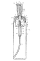
本発明の手動噴霧容器1は、容器体Aと、シリンダ部材Bと、作動部材Cとを備えている。
【0012】
容器体Aは、筒状の胴部2より口頸部3を起立している。
【0013】
シリンダ部材Bは、大径の空気シリンダ4の下部に小径の液体シリンダ5を延設して容器体A内へ垂下させている。図示例では、装着キャップDに空気シリンダ4の上端を固定しており、装着キャップDは、容器体Aの口頸部3外面へ嵌合させた周壁6上端より内向きフランジ状頂壁7を延設するとともに、頂壁7内周部から案内筒9を起立している。そして、空気シリンダ4の外周上部より外方へ突周設した断面鉤型の係合突条を上記頂壁7下面の係合凹部に嵌着させて固定しており、また、空気シリンダ4下端の内向きフランジ状底壁10内周から、小径の液体シリンダ5を垂下し、該シリンダ下端から吸い上げパイプ11を容器体内底部まで垂下する。
【0014】
作動部材Cは、液体シリンダ5内から起立するステム12上端部に押下ヘッド13を嵌着させるとともに、ステム中間部を空気シリンダ4内へ嵌合させた大径筒状ピストン14中心部に貫設し、且つ、押下ヘッド13の上部内に射出管15を横設して上方付勢状態で上下動可能に設けたものである。
【0015】
また、射出管15前方に穿設されたノズル孔16と空気シリンダ4内とを射出管15内を介して連通する空気噴出路aを設けるとともに、ノズル孔16とステム12内とを射出管15外周部を介して連通する液体流出路bを設け、作動部材の押し下げ時に、空気噴出路aを通りノズル孔16から噴出する空気により液体流出路b内が負圧化し、該負圧化で容器体内液体が吸い上げられ、噴出空気と混合して噴霧される如く構成している。
【0016】
図示例では、液体シリンダ5内周に嵌合した小径筒状ピストン17を下端部外周より突設したステム12の上端に押下ヘッド13を嵌着している。また、押下ヘッド13は、周壁18a 上端より頂壁18b を延設した下端開口の有頂筒状をなすケーシング18内上部に前端を開口した横筒19を横設し、また、この横筒19内に先端に噴出口を開口した射出管15を嵌着している。更に、この横筒19内に上端を連通させて垂下するとともに、下端部をステム12内周上端部に嵌合した縦内筒20と、該縦内筒20外周部分に垂下するとともに、ステム12外周上端部に下端部を隙間をあけて垂下した縦外筒21とを備えている。
【0017】
また、空気シリンダ4内へ嵌合させた大径筒状ピストン14の中央部に基筒部14a を貫設して、該基筒部14a の上部は押下ヘッド13の上記縦外筒21下部内面へ気密に、且つ小ストローク上下動可能に嵌合させる。又、ステム12は小径の液体シリンダ5内へ設けたコイルスプリング22で上方付勢させ、該上方付勢により、後述する可動弁体の下面を大径筒状ピストン14の隔壁部14b 上面へ、また、基筒部14a の下端面をステム12の中間部外面へ付設した受座23の上面へ、それぞれ圧接させている。
【0018】
大径筒状ピストン14の基筒部14a と、外周筒状部14c との間の隔壁部14b は、図示例において、その径方向中間部を起立筒部とし、且つ基筒部14a に接する隔壁部部分に複数の外気吸込み弁孔24を穿設し、また、基筒部14a の下部外面に合成樹脂製筒部25を気密に嵌着させるとともに、該筒部の下部外面から上外方へ外向きフランジ状弾性薄板26を突出して、該弾性薄板の外周縁を、外気吸込み弁孔24よりも外方の隔壁部14b 下面へ圧接させて、これらで外気吸込み弁27を形成している。
【0019】
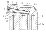
空気噴出路aは、基筒部14a の下端面から、ステム12と基筒部14a との間、ステム12と縦外筒21との間、縦内筒20と縦外筒21の間を通り射出管15内に連通し、更に、小空隙部28を通ってノズル孔16と連通する如く構成しており、また、液体流出路bは、ステム12内から縦内筒20内を介して横筒19に穿設した透孔29を通り、更に射出管15周囲の隙間30、小空隙部28を通ってノズル孔16と連通する如く構成している。更に、基筒部14a 下端面と受座23上面とで空気吐出弁31を、又、ステム12内に液止め弁32を設ける。
【0020】
また、ステム内には係合突条33を周設させている。小径液体シリンダ5の下部内面へ複数縦設した係合起立板の中間部内面に上向きの係合段部を設け、その係合起立板間に上下動自在に嵌合させた係合突子を下部外面に複数付設した棒34を液体シリンダ5内へ、棒上部はステム12内へ挿通させて遊嵌している。棒上端部は、半球状に上部を大径部としてその上部外面を、係合突条33上面へ水密に係合させ液漏れ防止弁35を形成している。また、その棒34を遊挿させて、小径シリンダ下部と小径筒状ピストン17との間には、上記コイルスプリング22を、該スプリング下端を係合起立板の係合段部上へ載置させて設けて、小径筒状ピストン17を介して作動部材Cを上方付勢し、該上方付勢により係合突条33を介して棒34を、係合突子がコイルスプリング22下端面へ圧接する状態に引き上げている。
【0021】
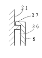
本発明ではこの種の手動噴霧容器に於いて、上記作動部材Cの押し下げ状態で係止可能に構成している。この様にすることにより、不用意に押し下げヘッドを押し下げる等を防止でき、無用な液の噴霧を防止することができる。具体的には種々の手段が採用できるが、本実施例では、図2に示す如く、押下ヘッド13の縦外筒21外面所定位置に挿通係合用のレール36を突縦設する一方、上記装着キャップDの案内筒9上端より内方へフランジ状の係止突条37を突設し、この係止突条37に上記レール36が挿通可能な案内切欠38を穿設する。そして、常時はレール36の下部が案内切欠38に押し下げ可能に嵌合して作動部材Cの上下動が可能に構成しており、また、必要に応じてレール36の上端が係止突条37の下面位置に至るまで作動部材Cを押し込んだ後回動させることによりレール36の上端が係止突条37下面に当接係止されて作動部材Cの押し下げ係止状態を維持する如く構成している。
【0022】
本実施例では、上記レール36の外に切り換え用の突条39を縦外筒21外面所定位置に突縦設し、一方、上記係止突条37の内面所定位置に相互の乗り越え係合が可能に一対の第1係合凹部40,第2係合凹部41を凹設している。そして、切り換え用の突条39が第1係合凹部40に係合している際に上記レール36が案内切欠38と係合し、第2係合凹部41に係合させた際にその位置からずれた係止突条位置に位置する如く構成している。
【0023】
本発明ではまた、上記空気シリンダ4に、噴霧に伴う容器体内の液の減少に当たって容器体A内が負圧化するのを防止するための外気導入孔hを設けるとともに、この外気導入孔hを開閉可能に閉塞する可動弁体Eを設けている。
【0024】
上記可動弁体Eは、上記作動部材Cが最下降の係止状態に移行した際に作動部材Cにより可動弁体Eが押し下げられて外気導入孔hの閉塞状態に移行するとともに、作動部材Cが最上昇状態に移行する際に大径筒状ピストン14により押し上げられて外気導入孔h開放状態に移行し、且つ、作動部材Cが液噴出のための上下動時には外気導入孔h開放状態を維持する如く構成している。
【0025】
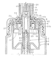
図示例に於いて可動弁体Eは、上記大径筒状ピストン14上方の空気シリンダ4内面に外周縁の筒状シール部42を嵌合させるとともに、該筒状シール部42より内方の上記縦外筒21外周近傍位置までフランジ状壁43を延設している。フランジ状壁43は中央へ昇る階段状をなし、下面より押圧用突部44を突設している。そして、上記コイルスプリング22による通常の上方付勢状態、即ち最上昇状態では大径筒状ピストン14により押圧用突部44が押し上げられて上面が装着キャップDの頂壁7下面に当接した状態で係止されている。この際筒状シール部42は外気導入孔h上方に位置している。
【0026】
また、縦外筒21の外面所定位置にはリブを突設することにより形成した下向き段部45を設けており、再上昇位置から作動部材Cを上記レール36が係止突条37に係合する位置、即ち最下降の係止状態まで押し下げると、途中で下向き段部45が可動弁体Eのフランジ状壁43上面内周縁部に当接し、その筒状シール部42が外気導入孔hを閉塞する位置まで押し下げる如く構成している。
【0027】
上記噴霧容器を使用する場合について説明すると、図1が示す状態から数回作動部材Cを上下動させることで液体シリンダ内に液体が入る。該状態から作動部材Cを押し下げすると、まず大径筒状ピストン14に対してステム12が押下ヘッド13とともに下降して空気吐出弁31が開き、次いで押下ヘッド13の縦外筒21下端が大径筒状ピストン14の隔壁部14b 上面に接して、空気吐出弁31を開いたままで大径筒状ピストンもステム12とともに下降する。
【0028】
このとき外気吸込み弁27は閉塞しているから、空気シリンダ4内の空気は空気噴出路a及び小空隙部28を通ってノズル孔16から噴出する。この時小空隙部28の外周部は負圧化するから、該小空隙部に連通する液体流出路b内も負圧化することとなり、よって液体流出路bを介して液体シリンダ5内液体が小空隙部28内へ吸い出され、該小空隙部内へ吸い出された液体は上記噴出空気と混合してノズル孔16から霧となって噴出する。
【0029】
押下ヘッド13を放すと空気噴出は停止するため、小空隙部28内の負圧状態が解消し、すると液止め弁32は閉塞する。また、大径筒状ピストン14に先だってステム12が上昇することで空気吐出弁31が閉じ、次いで大径筒状ピストン14も受座23で、引き上げられるため、空気シリンダ4内が負圧化し、よって外気吸込み弁27が開いて外気を空気シリンダ内へ吸入する。一方、液体シリンダ5内には吸い上げパイプ11を介して容器体A内の液が吸引される。尚、この際、可動弁体Eは図1の状態を維持しているため、外気導入孔hは開いた状態にあり、容器体内の液の減少による負圧化に伴い外気が外気導入孔hを介して容器体A内へ導入される。
【0030】
また、不使用時には作動部材Cを押し下げて回動させて上記係止突条37下面にレール36上面を係合させる。この際縦外筒21外面に設けた下向き段部45が可動弁体Eを押し下げて、その筒状シール部42が外気導入孔hを閉塞する位置まで押し下げる。従って、不使用時の作動部材Cの押し下げ係止時には常時外気導入孔hは閉塞されている。この際、液止め弁32の弁座下面の嵌合凹部46内に棒34先端が液密に嵌合してこの部分のシール性を図っている。また、その状態からレール36の係合を外して作動部材を上昇させると、大径筒状ピストン14により可動弁体Eは上端所定位置まで押し上げられる。尚、図示例では、ステム内面上端に嵌合させた嵌合筒の内面より、液止め弁のボール移動量を規制するリブを突設している。
【0031】
図7及び図8は本発明の他の実施例を示すもので、本実施例では、図1の実施例に於いて、コイルスプリング22を液体シリンダ5外部に介在させた例を示す。上記シリンダ部材Bに代えて、大径の空気シリンダ4の下部に小径のカバー筒47を延設し、該カバー筒47内に小径の液体シリンダ5を起立したシリンダ部材B1を備えている。そして、液体シリンダ5外周のカバー筒47底部とステム12の上記受座23との間にコイルスプリング22を介在させて作動部材Cを上方付勢させている。従って、性能上から金属製のものが好ましく使用されるコイルスプリング22を直接液と接触させることなく使用できるものであり、金属との接触を好まない収納液の使用が可能となり、その結果収納する液の制限が大幅に少なくなる。また、棒34の下端部を液体シリンダ5内下端部に、外周より突設した係止リブを嵌着固定している。その他の構成は図1の実施例と同様であるための説明を省略する。
【0032】
図9及び図10は本発明の更に他の実施例を示すもので、本実施例では、図1の実施例に於いて、上記シリンダ部材Bに代えて、大径の空気シリンダ4の下部に有底で小径のカバー筒47を延設し、そのカバー筒47の底壁より空気シリンダ4内に至る上下端開口の摺動用筒48を立設し、更に、摺動用筒48の上端部外周をステム12内周に上下摺動可能に嵌合させたシリンダ部材B2を備えている。また、ステム12は上記小径筒状ピストン17及び上記係合突条33を備えておらず、また、上記吸い上げパイプ11は摺動用筒48の上端部まで嵌着している。更に、上記受座23とカバー筒47の底壁との間にコイルスプリング22を介在させ、液との接触がないように構成している。また、摺動用筒48の上端部より上方に液の流通が可能な如く支持板を介して上記嵌合凹部46に液密に嵌合する嵌合突起49を延設している。その他の構成は図1の実施例と同様であるため説明を省略する。
【0033】
上記各部材は主として合成樹脂により形成し、必要に応じてエラストマー,金属等を併用して形成すると良い。
【0034】
【発明の効果】
以上説明した如く、本発明手動噴霧容器は、既述構成としたことにより、作動部材を押し下げ係止させておくことができ、その際、カバーキャップやストッパーなどの存在がなくても、空気シリンダに設けた外気導入孔を可動弁体が閉塞して不都合な液の漏出防止を図ることができるものである。しかも、可動弁体は作動部材が最上昇状態に移行する際に押し上げられて外気導入孔開放状態に移行し、作動部材が液噴出のための上下動時には外気導入孔開放状態を維持するため、通常の使用時には容器体への外気の円滑な導入が行えるとともに、作動部材を上下動させる際に自動的に可動弁体が所定の状態に移行できるため取り扱いも極めて便利である。
【図面の簡単な説明】
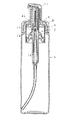
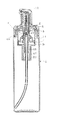
【図1】本発明の一実施例を示す縦断面図である。
【図2】同実施例の押し下げヘッドの係止機構を説明する説明図である。
【図3】同実施例の押し下げヘッドの係止機構を説明する説明図である。
【図4】同実施例の射出管部分の要部拡大断面図である。
【図5】同実施例の空気シリンダ部分の要部拡大断面図である。
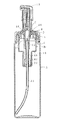
【図6】同実施例の作動部材を押し下げ係止した状態の縦断面図である。
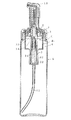
【図7】本発明の他の実施例を示す縦断面図である。
【図8】同実施例の作動部材を押し下げ係止した状態の縦断面図である。
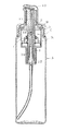
【図9】本発明の更に他の実施例を縦断面図である。
【図10】同実施例の作動部材を押し下げ係止した状態の縦断面図である。
【符号の説明】
4…空気シリンダ,12…ステム,13…押下ヘッド,15…射出管,
16…ノズル孔,a…空気噴出路,b…液体流出路,h…外気導入孔,
A…容器体,C…作動部材,E…可動弁体[0001]
BACKGROUND OF THE INVENTION
The present invention relates to a manual spray container.
[0002]
[Prior art]
As a manual spray container, there is known a so-called spin mechanism that rotates a sprayed liquid at high speed in a nozzle hole so that the liquid ejected from the nozzle hole while rotating at high speed comes into contact with the outside air and atomizes. . These may be difficult to atomize depending on the quality of the liquid contained in the container.
[0003]
In view of this, a manual spray container has been proposed that can suck up liquid with air that is ejected from a nozzle hole at high speed and eject the liquid together with air as a mist (see, for example, Patent Document 1).
[0004]
The spray container has a cylinder member that extends a small-diameter liquid cylinder below the large-diameter air cylinder at the top and hangs down into the container body, and a push-down head fitted on the upper part of the stem that stands up from the liquid cylinder. The middle part of the stem is penetrated into the center of the large-diameter cylindrical piston fitted into the air cylinder, and the injection pipe is installed in the upper part of the push-down head so that it can move up and down in the upward biased state. An air ejection path that communicates between the nozzle hole drilled forward of the injection tube through the injection tube and the inside of the air cylinder, and a liquid that communicates the nozzle hole and the stem along the outer surface of the injection tube When the operating member is pushed down, air in the air cylinder passes through the air ejection path and is ejected from the nozzle hole, so that the liquid outflow path becomes negative pressure and the negative pressure causes the liquid in the container to eject. Mixed with air It is made possible fog.
[0005]
These generally have an outside air introduction hole formed in the upper part of the air cylinder. These outside air introduction holes are for introducing the outside air into the container body that is negatively pressured as the liquid decreases when the operation member is moved up and down to spray the liquid in the container body. It is configured such that outside air is introduced into the container body through the outside air introduction hole from the gap with the inner peripheral edge of the mounting cap.
[0006]
[Patent Document 1]
Japanese Patent Laid-Open No. 11-239744 (page 2-7, FIG. 1)
[0007]
[Problems to be solved by the invention]
The manual spray container described above is excellent in that it can easily and surely atomize even a liquid that is difficult to atomize by increasing the injection air pressure.
[0008]
The present invention can demonstrate the advantages of the above-mentioned conventional product, and even if the container is tilted in a state where the operation member is pushed down and locked when not in use, it can be removed from the container body without the presence of a cover cap or a stopper. The present invention proposes an excellent pump that can prevent leakage of liquid into the air cylinder and can be easily manufactured without significant structural changes compared to conventional containers.
[0009]
[Means for Solving the Problems]
The first means is configured as follows. That is, a large-
[0010]
DETAILED DESCRIPTION OF THE INVENTION
Hereinafter, embodiments of the present invention will be described with reference to the drawings.
[0011]
The
[0012]
The container body A has the mouth-and-
[0013]
In the cylinder member B, a small-diameter
[0014]
The actuating member C is inserted in the central portion of the large-diameter
[0015]
In addition, an air ejection path a is provided that connects the
[0016]
In the illustrated example, a
[0017]
Further, a base tube portion 14a is provided in the center of the large-
[0018]
In the illustrated example, the
[0019]
The air ejection path a passes from the lower end surface of the base cylinder portion 14a between the
[0020]
Further, an engaging
[0021]
In the present invention, this type of manual spray container is configured to be able to be locked when the operating member C is pushed down. By doing so, it is possible to prevent the pressing head from being inadvertently pressed down and to prevent unnecessary liquid spraying. Specifically, various means can be employed, but in this embodiment, as shown in FIG. 2, a
[0022]
In the present embodiment, a switching
[0023]
In the present invention, the
[0024]
The movable valve body E moves to the closed state of the outside air introduction hole h while the movable valve body E is pushed down by the operating member C when the operating member C shifts to the lowest lowered locking state. Is pushed up by the large-
[0025]
In the illustrated example, the movable valve element E is fitted with a cylindrical seal portion 42 on the outer peripheral edge on the inner surface of the
[0026]
Further, a downward stepped
[0027]
The case where the spray container is used will be described. The liquid enters the liquid cylinder by moving the operating member C up and down several times from the state shown in FIG. When the operating member C is pushed down from this state, the
[0028]
At this time, since the outside air intake valve 27 is closed, the air in the
[0029]
When the
[0030]
Further, when not in use, the operating member C is pushed down and rotated to engage the upper surface of the
[0031]
7 and 8 show another embodiment of the present invention. In this embodiment, the
[0032]
9 and 10 show still another embodiment of the present invention. In this embodiment, in place of the cylinder member B in the embodiment of FIG. A bottomed, small-
[0033]
Each of the above members is mainly formed of a synthetic resin, and may be formed by using an elastomer, a metal, or the like as necessary.
[0034]
【The invention's effect】
As described above, since the manual spray container of the present invention has the above-described configuration, the operating member can be pushed down and locked, and even if there is no cover cap or stopper, the air cylinder The movable valve body closes the outside air introduction hole provided in, so that it is possible to prevent the leakage of inconvenient liquid. In addition, the movable valve body is pushed up when the operating member shifts to the highest state and shifts to the outside air introduction hole open state, and the operating member maintains the outside air introduction hole open state when moving up and down for liquid ejection. During normal use, outside air can be smoothly introduced into the container body, and the movable valve body can automatically shift to a predetermined state when the operating member is moved up and down, so that handling is extremely convenient.
[Brief description of the drawings]
FIG. 1 is a longitudinal sectional view showing an embodiment of the present invention.
FIG. 2 is an explanatory view for explaining a locking mechanism of the push-down head according to the embodiment.
FIG. 3 is an explanatory view for explaining a locking mechanism of the push-down head according to the embodiment.
FIG. 4 is an enlarged cross-sectional view of a main part of an injection tube portion of the same embodiment.
FIG. 5 is an enlarged cross-sectional view of a main part of an air cylinder portion of the same embodiment.
FIG. 6 is a longitudinal sectional view of a state in which the operating member of the same embodiment is pushed down and locked.
FIG. 7 is a longitudinal sectional view showing another embodiment of the present invention.
FIG. 8 is a longitudinal sectional view showing a state where the operation member of the embodiment is pushed down and locked.
FIG. 9 is a longitudinal sectional view of still another embodiment of the present invention.
FIG. 10 is a longitudinal sectional view showing a state in which the operating member of the same embodiment is pushed down and locked.
[Explanation of symbols]
4 ... Air cylinder, 12 ... Stem, 13 ... Pressing head, 15 ... Injection pipe,
16 ... Nozzle hole, a ... Air ejection passage, b ... Liquid outflow passage, h ... Outside air introduction hole,
A ... container body, C ... actuating member, E ... movable valve body
Claims (1)
Priority Applications (1)
| Application Number | Priority Date | Filing Date | Title |
|---|---|---|---|
| JP2003155905A JP4297253B2 (en) | 2003-05-30 | 2003-05-30 | Manual spray container |
Applications Claiming Priority (1)
| Application Number | Priority Date | Filing Date | Title |
|---|---|---|---|
| JP2003155905A JP4297253B2 (en) | 2003-05-30 | 2003-05-30 | Manual spray container |
Publications (2)
| Publication Number | Publication Date |
|---|---|
| JP2004358284A JP2004358284A (en) | 2004-12-24 |
| JP4297253B2 true JP4297253B2 (en) | 2009-07-15 |
Family
ID=34050175
Family Applications (1)
| Application Number | Title | Priority Date | Filing Date |
|---|---|---|---|
| JP2003155905A Expired - Fee Related JP4297253B2 (en) | 2003-05-30 | 2003-05-30 | Manual spray container |
Country Status (1)
| Country | Link |
|---|---|
| JP (1) | JP4297253B2 (en) |
Families Citing this family (5)
| Publication number | Priority date | Publication date | Assignee | Title |
|---|---|---|---|---|
| JP6993279B2 (en) * | 2018-03-30 | 2022-01-13 | 株式会社吉野工業所 | Foam ejector |
| FR3097781B1 (en) * | 2019-06-28 | 2021-09-17 | Albea Services | Push button for distribution system, with fluid path crossings |
| JP2024065852A (en) * | 2022-10-31 | 2024-05-15 | 株式会社吉野工業所 | Liquid Squirter |
| CN117002842B (en) * | 2023-07-14 | 2025-10-14 | 江苏伟创塑胶制品有限公司 | Lotion pump with adjustable spray volume |
| JP2025022240A (en) * | 2023-08-02 | 2025-02-14 | 株式会社リスニ | Liquid Spray Device |
-
2003
- 2003-05-30 JP JP2003155905A patent/JP4297253B2/en not_active Expired - Fee Related
Also Published As
| Publication number | Publication date |
|---|---|
| JP2004358284A (en) | 2004-12-24 |
Similar Documents
| Publication | Publication Date | Title |
|---|---|---|
| JP5645214B2 (en) | pump | |
| JP4297253B2 (en) | Manual spray container | |
| JP2004230316A (en) | Pump for jetting liquid | |
| JP3836312B2 (en) | Liquid jet pump | |
| JP4345921B2 (en) | Pump container | |
| JP5574370B2 (en) | Liquid ejector capable of upside-down ejection | |
| JP5126838B2 (en) | Liquid discharge container | |
| JP3667422B2 (en) | pump | |
| JP2011245463A (en) | Upright/invertedly jettable liquid jetting device | |
| JPH10181761A (en) | Ejecting device of liquid | |
| JP2520176Y2 (en) | Liquid ejector | |
| JP2003033686A (en) | Accumulator spray vessel | |
| JPH0418692Y2 (en) | ||
| JP3976885B2 (en) | Manual spray container | |
| JP3886680B2 (en) | Spray container | |
| JP3657378B2 (en) | Liquid jet pump | |
| JPH082130Y2 (en) | Liquid ejection container | |
| JP3527332B2 (en) | Pump container | |
| JP2520177Y2 (en) | Liquid ejector | |
| JP3810574B2 (en) | Vertical pump type spray container | |
| JP5688728B2 (en) | pump | |
| JP3609486B2 (en) | Foam ejection container | |
| JPH0418689Y2 (en) | ||
| JP2002066399A (en) | Vertical liquid ejection pump | |
| JP2550691Y2 (en) | Liquid ejection container |
Legal Events
| Date | Code | Title | Description |
|---|---|---|---|
| A621 | Written request for application examination |
Free format text: JAPANESE INTERMEDIATE CODE: A621 Effective date: 20051031 |
|
| A977 | Report on retrieval |
Free format text: JAPANESE INTERMEDIATE CODE: A971007 Effective date: 20080715 |
|
| A131 | Notification of reasons for refusal |
Free format text: JAPANESE INTERMEDIATE CODE: A131 Effective date: 20081112 |
|
| A521 | Request for written amendment filed |
Free format text: JAPANESE INTERMEDIATE CODE: A523 Effective date: 20090107 |
|
| TRDD | Decision of grant or rejection written | ||
| A01 | Written decision to grant a patent or to grant a registration (utility model) |
Free format text: JAPANESE INTERMEDIATE CODE: A01 Effective date: 20090408 |
|
| A01 | Written decision to grant a patent or to grant a registration (utility model) |
Free format text: JAPANESE INTERMEDIATE CODE: A01 |
|
| A61 | First payment of annual fees (during grant procedure) |
Free format text: JAPANESE INTERMEDIATE CODE: A61 Effective date: 20090408 |
|
| R150 | Certificate of patent or registration of utility model |
Ref document number: 4297253 Country of ref document: JP Free format text: JAPANESE INTERMEDIATE CODE: R150 Free format text: JAPANESE INTERMEDIATE CODE: R150 |
|
| FPAY | Renewal fee payment (event date is renewal date of database) |
Free format text: PAYMENT UNTIL: 20120424 Year of fee payment: 3 |
|
| FPAY | Renewal fee payment (event date is renewal date of database) |
Free format text: PAYMENT UNTIL: 20120424 Year of fee payment: 3 |
|
| FPAY | Renewal fee payment (event date is renewal date of database) |
Free format text: PAYMENT UNTIL: 20130424 Year of fee payment: 4 |
|
| FPAY | Renewal fee payment (event date is renewal date of database) |
Free format text: PAYMENT UNTIL: 20130424 Year of fee payment: 4 |
|
| FPAY | Renewal fee payment (event date is renewal date of database) |
Free format text: PAYMENT UNTIL: 20140424 Year of fee payment: 5 |
|
| LAPS | Cancellation because of no payment of annual fees |