JP4295076B2 - Dental prosthesis manufacturing model - Google Patents
Dental prosthesis manufacturing model Download PDFInfo
- Publication number
- JP4295076B2 JP4295076B2 JP2003413574A JP2003413574A JP4295076B2 JP 4295076 B2 JP4295076 B2 JP 4295076B2 JP 2003413574 A JP2003413574 A JP 2003413574A JP 2003413574 A JP2003413574 A JP 2003413574A JP 4295076 B2 JP4295076 B2 JP 4295076B2
- Authority
- JP
- Japan
- Prior art keywords
- model
- tooth
- mold
- dental prosthesis
- margin line
- Prior art date
- Legal status (The legal status is an assumption and is not a legal conclusion. Google has not performed a legal analysis and makes no representation as to the accuracy of the status listed.)
- Expired - Fee Related
Links
Images

Description
本発明は、歯科補綴物の製造に関し、特に、CAD/CAMを用いた製造に好適な歯科補綴物の製造方法に関するものである。 The present invention relates to the manufacture of a dental prosthesis, and more particularly to a method for manufacturing a dental prosthesis suitable for manufacturing using CAD / CAM.
歯科補綴物は、歯牙形成部位を補填して天然歯に近い歯牙に戻そうとするためのものであり、形成部位に一致し、形成前と変わらない歯牙状態に復元することが目的であるが、その製造には、多数の工程を要しているのが現状である。
この工程の中に、より簡便さを目的として、CAD/CAMの様なコンピュータを利用した計測、製造を取り込む試みが、提案されている。
The dental prosthesis is intended to replenish the tooth formation site and return to the tooth close to the natural tooth, and is intended to restore the tooth state that matches the formation site and does not change from before the formation. In the present situation, the manufacturing requires many steps.
Attempts have been made to incorporate measurement and manufacturing using a computer such as CAD / CAM into this process for the sake of simplicity.
この手法は、歯牙形成部位又は、その形成部位を復元した模型の表面形状を、接触プローブ、非接触レーザおよび光学式による撮影等の手法を用いて座標データ化し、この座標データを、修飾、修正した後、NC工作機械により補綴物ブロックを加工するものであり、人手を省いたコストの低い補綴物の製造を可能としている、しかし、最初の模型を作成する迄の工程は何ら変わるところはなく、その手段を踏襲するものであって、更にプローブによる接触計測、レーザ光等による非接触計測を行うには、密接した歯列環境では不可能であり、個々に模型を切り離して計測する等の煩雑さにより、CAD/CAMの有意性は希釈される。
又、マージンラインを模型から得る場合、複雑な模型製造時に製造工程で失われる等して、精度の高いマージンラインを得ることは不可能である。
In this method, the tooth formation site or the surface shape of the model where the formation site is restored is converted into coordinate data using techniques such as contact probe, non-contact laser and optical imaging, and this coordinate data is modified and modified. After that, the prosthesis block is processed by an NC machine tool, which makes it possible to manufacture a low-cost prosthesis without human labor, but there is no change in the process until the first model is created. In order to perform contact measurement using a probe and non-contact measurement using a laser beam, etc., it is impossible in a close dentition environment. Due to the complexity, the significance of CAD / CAM is diluted.
In addition, when a margin line is obtained from a model, it is impossible to obtain a margin line with high accuracy because it is lost in the manufacturing process when a complicated model is manufactured.
特開平04−253853号公報には、CAD/CAMにより補綴物を作成するための模型として、支台歯形成後、支台歯と、咬合歯間に印象材を配置し、当該印象材を両歯により挟圧して、咬合歯面と、支台歯表面状態を含む印象材を取得し、印象材に写し取られた形状から、模型を形成して、当該模型表面をCAD/CAMの接触プローブにより表面形状を測定した後、補綴物形状を得ることが記載されている。
特開平04−253853号公報では、咬合歯の表面と高さ、最大豊隆部を正確に得ることが開示されているが、マージンラインの正確な計測については、何ら開示されていない。
Japanese Patent Laid-Open No. 04-253853 discloses that the surface and height of the occlusal teeth and the maximum ridge are accurately obtained, but there is no disclosure about accurate measurement of the margin line.
上述のようにマージンライン(補綴物を装着した際の、補綴物と、天然歯の境界部分)は、支台歯形状を印象材により型取りする際、検出し得るものであり、そのタイミングを逃すと、再度印象を取る必要があるため、患者、医師に負担の増加をもたらす。
マージンラインは、補綴物を形成部位に挿入配置した後、天然歯と補綴物の境界を示すが、この境界に間隙があった場合、2次う蝕が生じることから、補綴物と天然歯との一致した結合が必要になるのである。
As described above, the margin line (boundary portion between the prosthesis and the natural tooth when the prosthesis is mounted) can be detected when the abutment tooth shape is molded with the impression material, and the timing thereof is determined. If you miss it, you need to take another impression, which increases the burden on patients and doctors.
The margin line indicates the boundary between the natural tooth and the prosthesis after the prosthesis is inserted and arranged in the formation site. If there is a gap in this boundary, secondary caries will occur. It is necessary to have a matched connection.
上記に鑑み本発明は、歯牙形成部位及びその隣接する領域の歯牙形状を得る印象取得ステップ、前記歯牙形成部位の形状からマージンライン等の特徴部位を形状的に抽出するステップ、取得された前記印象部位の隣接領域から、特徴部位形状までに硬化性部材を注入するステップにより、マージンラインを機械的、光学的計測に適した状態を有する型を形成しえることを可能としたものである。また、CAD/CAMに限らず、通常の一般技工作業でも、マージンライン等の特徴部位形状の抽出も簡便にすることを、可能としたものである。 In view of the above, the present invention provides an impression acquisition step of obtaining a tooth shape of a tooth forming part and its adjacent region, a step of extracting a characteristic part such as a margin line from the shape of the tooth forming part, and the acquired impression By injecting the curable member from the adjacent region to the feature site shape, it is possible to form a mold having a state suitable for mechanical and optical measurement of the margin line. Further, not only CAD / CAM but also normal general technical work, it is possible to easily extract the shape of a characteristic part such as a margin line.
本発明は、CAD/CAMで、補綴物を加工する際に必須となるパラメータであるマージンライン情報の正確な検出を印象取得時に簡便な作業で可能とする。また、CAD/CAMでの補綴物加工に限らず、通常の一般技工作業でも、マージンライン情報の正確な検出も簡便な作業で可能とする
本発明は、従来の模型製造工程を、大幅に逸脱しない範囲の作業で実施でき、歯科医師、歯科技工士に特別な教育を施すことなく、今までの作業で十分作成でき、安心感を与える。
The present invention enables accurate detection of margin line information, which is a parameter indispensable when processing a prosthesis, by CAD / CAM with a simple operation at the time of impression acquisition. In addition to the prosthesis processing by CAD / CAM, it is possible to accurately detect margin line information even with ordinary general technical work, with simple work. The present invention significantly deviates from the conventional model manufacturing process. It can be carried out in a range of work that can be done, and it can be created enough with the work so far without giving special training to dentists and dental technicians, giving a sense of security.
本発明における補綴物は、インレー、クラウン・ブリッジ等を示し、主に支台歯を形成した後、この支台歯上に補綴されるクラウンが、好適である。また、クラウンに限らず、インレー・ブリッジやその他の補綴物にも有効である。
本発明における歯牙形成部位及びその隣接する領域とは、補綴する歯牙の両側の歯牙を示し、補綴する歯牙が、2つ隣接すれば、その両側を示すが、片側にのみ歯牙がある場合は、片側のみであってもよい。
又、少なくとも、隣在領域であれば良く、隣在歯を含まない場合もある。即ち、本発明は、印象取得時、マージンラインを境界とする硬化剤の充填により第1の型が得られればよい。当該硬化剤としては、例えば 即時重合レジン、パターンレジン等が示されるが、これに限るものではい。
印象上にマージンラインを際だたせる凹凸を得るべく、圧排操作を行うことが好ましいが、圧排動作を行わなくても、印象上にマージンラインが見いだし得るのであれば、その部分の凹凸を際だたせる作業を行っても良い。
The prosthesis in the present invention is an inlay, a crown bridge, or the like. A crown that is prosthetic on the abutment tooth after mainly forming the abutment tooth is preferable. In addition to the crown, it is also effective for inlay bridges and other prostheses.
Tooth formation site and its adjacent region in the present invention indicate the teeth on both sides of the tooth to be prosthetic, and if two prosthetic teeth are adjacent to each other, indicate both sides, but if there is a tooth only on one side, Only one side may be sufficient.
In addition, at least the adjacent region may be used, and the adjacent tooth may not be included. That is, according to the present invention, it is only necessary to obtain the first mold by filling the curing agent with the margin line as a boundary when acquiring an impression. Examples of the curing agent include an immediate polymerization resin and a pattern resin, but are not limited thereto.
It is preferable to perform the exclusion operation to obtain the unevenness that makes the margin line stand out on the impression, but if the margin line can be found on the impression without performing the exclusion operation, the work to make the unevenness of that portion stand out May be performed.
第1の型を形成した後、更に第2の型を形成すべくその上から、硬化剤を充填する。
第2の型の為の硬化剤としては、例えば、石膏、速硬性超硬石膏等が例示されるが、これに限るものではい。
これらの型が硬化した後、第2の型上に第1の型が、結合した、型が形成される。
第1の型を、接触、非接触プローブ等により走査計測して、3次元データ化することで、最大豊隆部位の直径(歯間距離)、高さ、さらに頬舌的距離が得られる。そして、第2の型より、正確なマージンライン、支台歯表面形状が得られる。
また、最大豊隆部位の直径(歯間距離)、高さ、頬舌的距離などの情報は、事前に採得したバイトWAX等から得ることも可能である。
尚、第1の型から、正確なマージンラインを、接触、非接触プローブ等により走査計測して、3次元データ化し、第2の型より、支台歯表面形状が得られ、更に最大豊隆部位の直径(歯間距離)、高さが求められる場合もある。
当該型は、補綴物製造後、所望の補綴物が形成できたかどうか確認するために、又は補償するために用いることも可能である。
尚、当該型に対し、場合によってワックスアップにより、クラウン型が形成され、当該型の表面形状をCAD/CAMで計測して3次元データ化しても良い場合もある。
さらに当該型は、CAD/CAMによる3次元データ化以外にも、通常の一般技工作業にも適応可能なものである。
After forming the first mold, a curing agent is filled from above to form a second mold.
Examples of the curing agent for the second mold include, but are not limited to, gypsum and quick-hard cemented gypsum.
After these molds are cured, a mold is formed in which the first mold is bonded onto the second mold.
By scanning and measuring the first mold with a contact or non-contact probe or the like and converting it into three-dimensional data, the diameter (interdental distance), height, and further buccal tongue distance of the maximum ridge is obtained. An accurate margin line and an abutment tooth surface shape can be obtained from the second mold.
In addition, information such as the diameter (interdental distance), height, and buccal distance of the maximum ridge can be obtained from a bite WAX or the like obtained in advance.
From the first mold, an accurate margin line is scanned and measured with a contact or non-contact probe, etc., and converted into three-dimensional data. There are cases where the diameter (interdental distance) and the height of the are required.
The mold can also be used to check if the desired prosthesis has been formed or to compensate after the prosthesis has been manufactured.
In some cases, a crown mold may be formed on the mold by waxing up, and the surface shape of the mold may be measured by CAD / CAM to form three-dimensional data.
Further, the mold can be applied not only to the three-dimensional data conversion by CAD / CAM but also to normal general technical work.
本発明は、印象取得時に、少なくともマージンラインを示す凸部を印象内に形成する。
その作業は、患者がいる状態で行われることから確認も容易である。
マージンラインを示す凸部は、少なくとも第1の型を得る時の硬化剤が留まる程度のものであれば良く、凸部でなく、凹部であっても良い場合もある。又、多少の目印的な凹凸にたいし、修飾的作業を行い、凹凸を形成しても良い。
In the present invention, at the time of impression acquisition, a convex portion showing at least a margin line is formed in the impression.
Since the work is performed in a state where there is a patient, confirmation is easy.
The convex portion showing the margin line is not limited to the convex portion and may be a concave portion as long as the curing agent at the time of obtaining the first mold is retained. In addition, irregularities may be formed by performing a modification work on some landmarks.
以下に本発明の実施例を図面を参照して詳細に説明する。
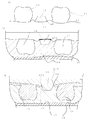
図1(a)は、支台歯13形成後の状態であり、隣在歯を11,12で示す。
予めマージンライン15を浮かび上がらせる為の、圧排作業が施された状態を示す。圧排作業は、支台歯13のマージンライン15が、歯肉14に隠れた状態に対し、歯肉を押し広げ、一時的に固定するための作業であって、その周辺に圧排糸を巻きつけ、糸を巻き付けた部分の歯肉は押し広げられた状態で一時的に固定される。圧排作業は、歯肉を押し広げることをが目的であるため、圧排糸以外の材料・薬剤であってもよく、圧排用の薬液を含侵又は付着可能で、歯肉と歯牙の間に挿入できる担体を使用してもよい。圧排部分をAPで示す。
Embodiments of the present invention will be described below in detail with reference to the drawings.
FIG. 1A shows a state after the
A state in which a pressure removal operation for raising the
次にトレー10に充填した印象材16を、支台歯13、隣在歯11,12の周辺に押し当て、印象をとる。印象をとった後を図1(b)に示す。支台歯凹部18周辺のマージンライン部20は圧排部分APAとして突出した状態で、印象がとれ、17,19は、図1(a)に示す隣在歯11,13に相当する隣在歯凹部、が形成される。18は、図1(a)の支台歯13の表面形状に相当する部分の支台歯凹部である。
トレー10の印象材16において、速乾性重合レジン材21を圧排部分APAで強調されたマージンライン部20を境界として隣在歯によって形成された凹部17,19に充填し、第1の型21を形成する。また、圧排部分APAで強調されたマージンライン部20を境界とした部分にパラフィンWAX等を充填した方が良い場合もある。
更に硬化剤を印象材16の全域に充填する(図1(c))。
Next, the
In the
Further, a curing agent is filled in the entire area of the impression material 16 (FIG. 1C).
硬化後、図2(a)で示すように第1の型21は、隣在する歯牙の型を形成し、第2の型22は、支台歯の部分26を中心として形成される。圧排部分は、マージンラインを特化させるための部分であり、必要に応じ、切り取る場合もある。
第1の型21と第2の型22は、着脱自在な状態となり、結合した状態は、図2(b)で示すものとなる。
当該型は、その表面形状を接触式、非接触式の計測プローブ、または光学式による撮影等の手法により計測する。その際、支台歯表面形状及びマージンラインを測定するために、第2の型より切断した分離体29としてもよい。
After the curing, as shown in FIG. 2A, the
The
The mold measures the surface shape using a contact-type or non-contact-type measurement probe or an optical imaging method. At that time, in order to measure the surface shape of the abutment tooth and the margin line, the
計測は、第2の型のマージンライン30を計測するか、第1の型21のマージンライン部分23計測するものであるが、第1の型21のマージンライン23を計測する方が、分離体29を製造しなくても良い点で好ましい場合もある。
更に、第1の型より、最大豊隆部の長さ27および頬舌長さが計測され、歯高値28を計測することも可能である。また、歯高値28は、第1の型21の上に事前に採得したバイトWAXを設置し、それを計測することも可能である。
第1の型21と、第2の型22は、結合したまま測定する場合や、分離した状態で測定する場合があるが、分離して計測する場合は、予め共通する位置情報を設定しておくことで、3次元データ上での第1の型データと第2の型データの結合が容易になる。
The measurement is performed by measuring the margin line 30 of the second mold or measuring the
Furthermore, from the first mold, the length 27 and the cheek tongue length of the maximum ridge are measured, and the
The
このマージンライン30の3次元データ及び、最大豊隆部に相当する径27,歯高値28を計測してデータ化した後、仮想補綴物3次元データ化して評価し、このデータに基づいて未加工ブロックの研削、切削加工、その他、レーザー照射による光硬化を利用したラピッドプロトタイプ加工、その他の加工により、補綴物を形成する。
加工は、データをインターネット等を介して、技工能力を有するセンターに伝送して、加工してもらうほか、自ら所持するNC加工装置に入力して、公知の手法で加工する。
加工後、この補綴物を第1の型と、第2の型に当てはめて、その仕上がりを確認することができる。
After measuring the three-dimensional data of the margin line 30 and the diameter 27 and the
For the processing, the data is transmitted to a center having technical ability through the Internet or the like to be processed, and is input to an NC processing apparatus possessed by itself and processed by a known method.
After processing, this prosthesis can be applied to the first mold and the second mold, and the finish can be confirmed.
本発明は、より正確な補綴物を製造することができると共に、従来、前処理としてのトリミング作業を常に必要とせず、技工士、歯科医師が簡便に補綴物を製造することができる。 According to the present invention, a more accurate prosthesis can be manufactured, and conventionally, a trimming operation as a pretreatment is not always required, and a technician and a dentist can easily manufacture a prosthesis.
10 トレー
11、12 隣在歯
13 支台歯
14 歯肉
15 マージンライン
16 印象材
17、19 隣在歯凹部
18 支台歯凹部
20、30 マージンライン部
21 第1の型
22 第2の型
10
Claims (3)
前記模型は、前記支台歯を中心として隣在歯の一部又は全部の領域から得られた凹模型の内のマージンラインからなる凹凸部を境界として、その周辺に硬化剤を注入して硬化させた最大豊隆部情報、隣在歯間の距離、高さ及びその周辺の形状データが得られる第1の模型と、更に前記支台歯に対応する凹部と前記第1の模型上に硬化剤を注入して硬化させることで形成された支台歯形状及びマージンラインが計測可能な第2の模型とで形成され、前記第1の模型と前記第2の模型は結合及び分離が可能である歯科補綴物製造用模型。 Measure the surface shape of the model obtained by filling the mold that has the shape of the area including part or all of the abutment teeth and adjacent teeth as a recess and then curing, using a measurement probe or optical imaging Then, in the dental prosthesis manufacturing model for producing the prosthesis by producing three-dimensional data of the shape of the dental prosthesis from these measured values and processing the raw blocks based on the three-dimensional data. ,
The model is hardened by injecting a hardener around the concave / convex part consisting of a margin line in a concave model obtained from a part or all of the adjacent tooth centered on the abutment tooth. The first model from which the information on the maximum ridges, the distance between adjacent teeth, the height, and the shape data of the surroundings is obtained, and the concave portion corresponding to the abutment tooth and the hardener on the first model. The abutment tooth shape formed by injecting and hardening and the second model capable of measuring the margin line are formed, and the first model and the second model can be combined and separated. Dental prosthesis manufacturing model.
Priority Applications (1)
| Application Number | Priority Date | Filing Date | Title |
|---|---|---|---|
| JP2003413574A JP4295076B2 (en) | 2003-12-11 | 2003-12-11 | Dental prosthesis manufacturing model |
Applications Claiming Priority (1)
| Application Number | Priority Date | Filing Date | Title |
|---|---|---|---|
| JP2003413574A JP4295076B2 (en) | 2003-12-11 | 2003-12-11 | Dental prosthesis manufacturing model |
Publications (3)
| Publication Number | Publication Date |
|---|---|
| JP2005168825A JP2005168825A (en) | 2005-06-30 |
| JP2005168825A5 JP2005168825A5 (en) | 2007-02-01 |
| JP4295076B2 true JP4295076B2 (en) | 2009-07-15 |
Family
ID=34733675
Family Applications (1)
| Application Number | Title | Priority Date | Filing Date |
|---|---|---|---|
| JP2003413574A Expired - Fee Related JP4295076B2 (en) | 2003-12-11 | 2003-12-11 | Dental prosthesis manufacturing model |
Country Status (1)
| Country | Link |
|---|---|
| JP (1) | JP4295076B2 (en) |
Cited By (1)
| Publication number | Priority date | Publication date | Assignee | Title |
|---|---|---|---|---|
| KR20190074062A (en) | 2017-12-19 | 2019-06-27 | 주식회사 디디에스 | Method for setting Gingival line to design prosthesis |
Families Citing this family (3)
| Publication number | Priority date | Publication date | Assignee | Title |
|---|---|---|---|---|
| US20080193901A1 (en) * | 2005-07-26 | 2008-08-14 | Oh-Dal Kwon | Dental Prosthesis and Its Manufacturing Method |
| JP2011229839A (en) | 2010-04-30 | 2011-11-17 | Gc Corp | Block for fabricating denture base |
| AT522914A1 (en) * | 2019-09-03 | 2021-03-15 | Eap® Produktions Und Patentverwertungs Gmbh | Method for producing a computer model for an abutment and an abutment |
-
2003
- 2003-12-11 JP JP2003413574A patent/JP4295076B2/en not_active Expired - Fee Related
Cited By (1)
| Publication number | Priority date | Publication date | Assignee | Title |
|---|---|---|---|---|
| KR20190074062A (en) | 2017-12-19 | 2019-06-27 | 주식회사 디디에스 | Method for setting Gingival line to design prosthesis |
Also Published As
| Publication number | Publication date |
|---|---|
| JP2005168825A (en) | 2005-06-30 |
Similar Documents
| Publication | Publication Date | Title |
|---|---|---|
| Lee et al. | Comparing accuracy of denture bases fabricated by injection molding, CAD/CAM milling, and rapid prototyping method | |
| Mai et al. | Fit of interim crowns fabricated using photopolymer-jetting 3D printing | |
| Jeong et al. | Accuracy evaluation of dental models manufactured by CAD/CAM milling method and 3D printing method | |
| US11865653B2 (en) | Method for producing a dentist tool | |
| US20190239988A1 (en) | System for the Construction of a Dental Prosthesis | |
| JP5875972B2 (en) | Dental CAD / CAM equipment | |
| US6568936B2 (en) | Method and apparatus for preparing dental restorations | |
| KR100678362B1 (en) | Production of replacement teeth from a three-dimensionally determined and digitised positive model | |
| KR101340971B1 (en) | Method and apparatus for obtaining data for a dental component and a physical dental model | |
| EP2101678B1 (en) | Method and system for dental planning and production | |
| AU2010209671B2 (en) | Method for producing a dentist tool | |
| CN111281581B (en) | Method for designing and manufacturing a dental component | |
| US20170151046A1 (en) | Dental prosthesis for determining abrasion facets | |
| CN104116569A (en) | Computer fabrication of dental prosthetic | |
| US20040089962A1 (en) | Method for producing dental restoration elements | |
| CA2490183C (en) | Method of producing a dental ceramic structure | |
| CN211534911U (en) | Wax bite mould for scanning | |
| JP4295076B2 (en) | Dental prosthesis manufacturing model | |
| US20030003420A1 (en) | Process for producing a dental prosthesis | |
| RU2721891C1 (en) | Method for making removable dental prosthesis | |
| Moglioni et al. | Intra-oral scanning and CAD/CAM prosthesis fabrication | |
| AU2015201878B2 (en) | A dentist tool | |
| Measar et al. | A Comparison Between Virtual Models Obtained by Intraoral Scanner and Their Three Dimensionally Printed Models | |
| 전진 | EVALUATION OF THE ACCURACY OF DENTAL MODELS FABRICATED BY VARIOUS 3D PRINTERS | |
| JP2004000331A (en) | Method for forming dental prosthesis |
Legal Events
| Date | Code | Title | Description |
|---|---|---|---|
| A521 | Written amendment |
Free format text: JAPANESE INTERMEDIATE CODE: A523 Effective date: 20061208 |
|
| A621 | Written request for application examination |
Free format text: JAPANESE INTERMEDIATE CODE: A621 Effective date: 20061208 |
|
| A977 | Report on retrieval |
Free format text: JAPANESE INTERMEDIATE CODE: A971007 Effective date: 20080526 |
|
| A131 | Notification of reasons for refusal |
Free format text: JAPANESE INTERMEDIATE CODE: A131 Effective date: 20080606 |
|
| A521 | Written amendment |
Free format text: JAPANESE INTERMEDIATE CODE: A523 Effective date: 20080804 |
|
| A02 | Decision of refusal |
Free format text: JAPANESE INTERMEDIATE CODE: A02 Effective date: 20081202 |
|
| A521 | Written amendment |
Free format text: JAPANESE INTERMEDIATE CODE: A523 Effective date: 20090116 |
|
| A521 | Written amendment |
Free format text: JAPANESE INTERMEDIATE CODE: A523 Effective date: 20090227 |
|
| A911 | Transfer of reconsideration by examiner before appeal (zenchi) |
Free format text: JAPANESE INTERMEDIATE CODE: A911 Effective date: 20090304 |
|
| TRDD | Decision of grant or rejection written | ||
| A01 | Written decision to grant a patent or to grant a registration (utility model) |
Free format text: JAPANESE INTERMEDIATE CODE: A01 Effective date: 20090401 |
|
| A01 | Written decision to grant a patent or to grant a registration (utility model) |
Free format text: JAPANESE INTERMEDIATE CODE: A01 |
|
| A61 | First payment of annual fees (during grant procedure) |
Free format text: JAPANESE INTERMEDIATE CODE: A61 Effective date: 20090409 |
|
| FPAY | Renewal fee payment (prs date is renewal date of database) |
Free format text: PAYMENT UNTIL: 20120417 Year of fee payment: 3 |
|
| R150 | Certificate of patent (=grant) or registration of utility model |
Free format text: JAPANESE INTERMEDIATE CODE: R150 |
|
| FPAY | Renewal fee payment (prs date is renewal date of database) |
Free format text: PAYMENT UNTIL: 20130417 Year of fee payment: 4 |
|
| LAPS | Cancellation because of no payment of annual fees |