JP4294692B2 - Information processing system - Google Patents

Information processing system Download PDF

Info

Publication number
JP4294692B2
JP4294692B2 JP2007002432A JP2007002432A JP4294692B2 JP 4294692 B2 JP4294692 B2 JP 4294692B2 JP 2007002432 A JP2007002432 A JP 2007002432A JP 2007002432 A JP2007002432 A JP 2007002432A JP 4294692 B2 JP4294692 B2 JP 4294692B2
Authority
JP
Japan
Prior art keywords
storage device
data
journal
logical storage
host
Prior art date
Legal status (The legal status is an assumption and is not a legal conclusion. Google has not performed a legal analysis and makes no representation as to the accuracy of the status listed.)
Expired - Fee Related
Application number
JP2007002432A
Other languages
Japanese (ja)
Other versions
JP2007179552A (en
JP2007179552A5 (en
Inventor
賢哲 江口
和彦 茂木
康友 山本
高 大枝
弘治 荒井
Current Assignee (The listed assignees may be inaccurate. Google has not performed a legal analysis and makes no representation or warranty as to the accuracy of the list.)
Hitachi Ltd
Original Assignee
Hitachi Ltd
Priority date (The priority date is an assumption and is not a legal conclusion. Google has not performed a legal analysis and makes no representation as to the accuracy of the date listed.)
Filing date
Publication date
Application filed by Hitachi Ltd filed Critical Hitachi Ltd
Priority to JP2007002432A priority Critical patent/JP4294692B2/en
Publication of JP2007179552A publication Critical patent/JP2007179552A/en
Publication of JP2007179552A5 publication Critical patent/JP2007179552A5/ja
Application granted granted Critical
Publication of JP4294692B2 publication Critical patent/JP4294692B2/en
Anticipated expiration legal-status Critical
Expired - Fee Related legal-status Critical Current

Links

Images

Description

本発明は、計算機や記憶装置システムを含む情報処理システムに関し、特に、障害などによって破壊された記憶装置システムに格納されたデータを復旧する情報処理システム及びそのデータ復旧方法に関する。   The present invention relates to an information processing system including a computer and a storage device system, and more particularly to an information processing system for recovering data stored in a storage device system destroyed due to a failure or the like and a data recovery method thereof.

情報処理システムで行われるオンライン処理やバッチ処理では、プログラムのバグや記憶装置システムの障害などによってこれらの処理が異常終了し、情報処理システムが有する記憶装置システムに格納されたデータが矛盾した状態になってしまうことがある。また、人為的ミスによって記憶装置システムに格納されたデータが消去されてしまうことも多い。   In online processing and batch processing performed in an information processing system, such processing ends abnormally due to a program bug or a storage system failure, and the data stored in the storage system of the information processing system becomes inconsistent. It may become. In addition, data stored in the storage device system is often erased due to human error.

このような状態になった情報処理システムのデータを回復させる目的で、データの矛盾を解消して途中で止まった処理を再開させたり、あるいは、途中で止まった処理をもう一度やり直したりするための技術の一つとして、データのバックアップとリストアによるデータ回復技術がある。   Technology for resolving data inconsistencies and resuming processes that stopped in the middle, or redoing processes that stopped in the middle for the purpose of recovering data in an information processing system that has entered such a state One of them is data recovery technology by data backup and restoration.

バックアップおよびリストアに関する従来技術の一つが、特許文献1に開示されている。本文献には、ユーザが指定した時点における記憶装置システムに格納されたデータを、記憶装置システムに接続された計算機(以下「ホスト」)からのデータの入出力(以下「I/O」)を止めることなく磁気テープに複製し(以下データの複製を「データのバックアップ」と称する)、その複製されたデータ(以下、「バックアップデータ」)を用いてデータの回復(以下「リストア」)する技術が開示されている。   One conventional technique relating to backup and restoration is disclosed in Japanese Patent Application Laid-Open No. 2004-133830. In this document, data stored in the storage device system at the time specified by the user is input / output (hereinafter “I / O”) of data from a computer (hereinafter “host”) connected to the storage device system. A technology for copying data to magnetic tape without stopping (hereinafter referred to as “data backup”), and using the copied data (hereinafter referred to as “backup data”) to recover data (hereinafter referred to as “restore”). Is disclosed.

一方、特許文献2には、データのリストアにかかる時間を短縮するために、データのバックアップが実行された後、データが更新された個所についての情報を差分情報として保持し、記憶装置システムに格納されたデータをバックアップデータでリストアする際に、バックアップデータのうち、差分情報で示されるデータの部分のみをデータのリストアに用いる技術が記載されている。
米国特許番号5,263,154号公報 特開2001−216185号公報
On the other hand, in Patent Document 2, in order to shorten the time required for data restoration, after data backup is executed, information about the location where the data is updated is held as difference information and stored in the storage device system. A technique is described in which, when restoring the recorded data with backup data, only the data portion indicated by the difference information is used for restoring the data in the backup data.
US Patent No. 5,263,154 JP 2001-216185 A

特許文献1に記載されたリストア処理では、磁気テープからバックアップデータを読み出す際、バックアップデータを取得した時点から更新されていない部分(記憶装置システムのデータと磁気テープのデータの内容が一致している部分)も磁気テープから読み出され、記憶装置システムに書き込まれる。このようなデータの転送は、無駄が多く、リストアに要する時間を長びかせる。   In the restoration process described in Patent Document 1, when backup data is read from the magnetic tape, the portion that has not been updated since the backup data was acquired (the contents of the data in the storage device system and the data on the magnetic tape match. Part) is also read from the magnetic tape and written to the storage system. Such data transfer is wasteful and lengthens the time required for restoration.

一方、特許文献2に開示されている技術では、特許文献1に比べ、重複したデータの読み出しが発生しない分、リストアに係る時間は少なくなる。しかし、双方の技術をもってしても、データのバックアップの後から記憶装置システムが故障するまでの間に更新されたデータについては、データのリストアを行うことができない。データのバックアップ後に更新されたデータまでリストアしようとすると、そのデータの更新の内容等をホスト側がログ等で管理する必要があり、ホストへの負荷が大きく、かつ処理に長い時間がかかる。   On the other hand, in the technique disclosed in Patent Document 2, as compared with Patent Document 1, the time required for restoration is reduced because duplicate data is not read out. However, even with both techniques, it is not possible to restore data for data that has been updated since the backup of the data until the storage system failed. If it is attempted to restore data updated after data backup, it is necessary for the host side to manage the contents of the update of the data in a log or the like, which places a heavy load on the host and takes a long time for processing.

本発明の目的は、障害発生前までの任意の時点におけるデータのリストア処理を高速に行う記憶装置システム並びに情報処理システムを提供することである。   An object of the present invention is to provide a storage device system and an information processing system that perform high-speed data restoration processing at an arbitrary time point before a failure occurs.

上記目的を達成するために、本発明は以下の構成を有する。すなわち、計算機及び計算機に接続された記憶装置システムを有する情報処理システムであり、記憶装置システムは制御部及び複数の記憶装置を有する。そして、記憶装置システムは、所定の指示にしたがって、一つの記憶装置に格納されたデータを他の記憶装置に複製する。その後、記憶装置システムは、複製元となった記憶装置へのデータ更新を更新履歴として他の記憶装置に格納する。一方、計算機は、複製が作成された後の任意の時間において、ある識別情報を作成し、記憶装置システムへ送信する。識別情報を受信した記憶装置システムは、その識別情報を更新履歴と関連させて記憶装置へ格納する。   In order to achieve the above object, the present invention has the following configuration. That is, the information processing system includes a computer and a storage device system connected to the computer, and the storage device system includes a control unit and a plurality of storage devices. Then, the storage device system duplicates data stored in one storage device to another storage device in accordance with a predetermined instruction. Thereafter, the storage device system stores the data update to the storage device that has become the copy source in another storage device as an update history. On the other hand, the computer creates certain identification information and transmits it to the storage device system at an arbitrary time after the copy is created. The storage device system that has received the identification information stores the identification information in the storage device in association with the update history.

データを復元させたい場合、計算機は、記憶装置システムへ識別情報を送信する。識別情報を受信した記憶装置システムは、記録した識別情報から受信した識別情報と一致する識別情報を検索する。一致する識別情報を発見したら、記憶装置システムは、複製先の記憶装置に格納されたデータと、一致した識別情報と関連付けられる更新履歴より前に記録された更新履歴の内容を用いて、複製元の記憶装置にデータを復元する。   When it is desired to restore data, the computer transmits identification information to the storage device system. The storage device system that has received the identification information searches the identification information that matches the received identification information from the recorded identification information. If the matching identification information is found, the storage system uses the data stored in the copy destination storage device and the contents of the update history recorded before the update history associated with the matching identification information, Data is restored to the storage device.

尚、本発明では、記憶装置システムへデータの更新を要求する計算機は、識別情報を作成する計算機と異なる構成も考えられる。   In the present invention, the computer that requests the storage system to update data may have a different configuration from the computer that creates the identification information.

また、本発明では、識別情報を作成する計算機は、その識別情報を自計算機に格納する構成も考えられる。   In the present invention, a computer that creates identification information may be configured to store the identification information in its own computer.

更に、本発明では、計算機に格納された識別情報に関する情報をユーザに提示し、ユーザの指定した識別情報を記憶装置システムへ送信する構成も考えられる。   Furthermore, in the present invention, a configuration in which information related to identification information stored in the computer is presented to the user and the identification information designated by the user is transmitted to the storage device system is also conceivable.

更に、本発明の構成として、以下が考えられる。すなわち、中央処理装置を備えた計算機と、記憶装置を備えた記憶装置システムとを有する構成とする。計算機は、記憶装置システムに対して記憶装置に格納されているデータの複製の作成保存を要求する手段、計算機の処理によるデータの更新部分の記録を要求する手段、及びシステムのある時点の状態を識別する識別情報を記憶装置システムに送信する手段とを保持する。記憶装置システムは、計算機の要求に応答して、記憶装置のデータの複製を作成保存する手段、記憶装置の内容が更新されたときに更新前後のデータ及び更新場所をジャーナルデータとして保存する手段、計算機より送信される識別情報を保持識別する手段、並びにジャーナルデータと識別情報を関連付ける手段を有する。更に、計算機は、記憶装置の内容をある時点の状態に復旧する必要が生じた場合、状態識別情報を指定してデータの復旧要求を記憶装置システムに送信する手段を有し、記憶装置システムは送信された状態識別情報を識別し、前記データの複製とジャーナルデータを用いてデータをリストアする手段を有する。   Furthermore, the following can be considered as a configuration of the present invention. That is, the computer has a central processing unit and a storage device system having a storage device. The computer requests the storage system to create and save a copy of the data stored in the storage device, request to record the updated portion of the data by the processing of the computer, and the state of the system at a certain point in time Means for transmitting identification information for identification to the storage device system. The storage device system is a means for creating and saving a copy of the data in the storage device in response to a request from the computer, a means for saving the data before and after the update and the update location as journal data when the contents of the storage device are updated, Means for holding and identifying identification information transmitted from the computer, and means for associating the journal data with the identification information. Further, the computer has means for designating the state identification information and transmitting a data recovery request to the storage device system when it becomes necessary to restore the contents of the storage device to a state at a certain point in time. Means for identifying the transmitted state identification information and restoring the data using the data copy and journal data.

更に本発明は、以下の構成を有する。即ち、計算機及び記憶装置システムで一つの識別情報を共有し、記憶装置システムではその識別情報と更新履歴を関連付けて管理し、計算機の指示に応じて、特定の識別情報で示される更新履歴まで、記憶装置に格納されたデータを復元するデータの復元方法である。   Furthermore, this invention has the following structures. In other words, the computer and the storage device system share one piece of identification information, and the storage device system manages the identification information in association with the update history, up to the update history indicated by the specific identification information in accordance with the instructions of the computer. A data restoration method for restoring data stored in a storage device.

本発明によれば、記憶装置システムに格納されたデータを復旧する場合に、ホストに負担をかけず、短時間でデータを所定の状態までリストアすることができる。また、ユーザは、任意のシステム状態までデータをリストアすることができる。   According to the present invention, when data stored in a storage device system is restored, data can be restored to a predetermined state in a short time without imposing a burden on the host. In addition, the user can restore data to any system state.

以下、図面を用いて、本発明の第一の実施形態について説明する。尚、これにより本発明が限定されるものではない。以下、「記憶装置システム」には、ディスク装置等の記憶装置、ディスクアレイ等のように複数の記憶装置を有するシステムが含まれるものとする。   Hereinafter, a first embodiment of the present invention will be described with reference to the drawings. Note that the present invention is not limited thereby. Hereinafter, the “storage device system” includes a storage device such as a disk device, and a system having a plurality of storage devices such as a disk array.

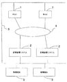
図1は、本発明を適用した情報処理システムの第一の実施形態を示す図である。情報処理システムは、ホスト1、記憶装置システム2、管理端末3、ホスト1と記憶装置システム2とを接続するネットワーク4、並びにホスト1、記憶装置システム2及び管理端末3とを接続するネットワーク5を有する。   FIG. 1 is a diagram showing a first embodiment of an information processing system to which the present invention is applied. The information processing system includes a host 1, a storage device system 2, a management terminal 3, a network 4 that connects the host 1 and the storage device system 2, and a network 5 that connects the host 1, the storage device system 2, and the management terminal 3. Have.

ホスト1は、パーソナルコンピュータ、ワークステーション、メインフレーム等の計算機である。ホスト1では、その計算機の種類に応じたオペレーティングシステム(以下「OS」)と様々な業務、用途に対応したアプリケーションプログラム(AP)、たとえばデータベース(DB)プログラム等、が動作する。本実施形態では、簡単のため、ホスト1を2つ記載しているが、ネットワーク4及び5に接続されるホスト1は幾つあってもよい。   The host 1 is a computer such as a personal computer, a workstation, or a main frame. In the host 1, an operating system (hereinafter referred to as “OS”) corresponding to the type of the computer and an application program (AP) corresponding to various tasks and uses, such as a database (DB) program, operate. In this embodiment, two hosts 1 are described for simplicity, but there may be any number of hosts 1 connected to the networks 4 and 5.

管理端末3は、記憶装置システム2の障害、保守、構成、性能情報等の管理を行うために使用される計算機である。例えば、情報処理システムの管理者が、記憶装置システム2に論理的な記憶装置を設定する場合、データをバックアップするための記憶領域を設定する場合、又はデータを複製する際の記憶領域の対を設定する場合に、管理端末3が使用される。情報処理システムの管理者は、記憶装置システム2の保守・管理、記憶装置システム2が有する物理記憶装置10の設定、及び記憶装置システム2と接続されるホスト1の設定等を行う場合に、管理端末3に設定したい内容を入力する。管理端末3は、ネットワーク5を介して記憶装置システム2及びホスト1に管理者が入力した内容を送信する。   The management terminal 3 is a computer used for managing faults, maintenance, configuration, performance information, and the like of the storage system 2. For example, when the administrator of the information processing system sets a logical storage device in the storage device system 2, sets a storage region for backing up data, or sets a pair of storage regions when copying data When setting, the management terminal 3 is used. The administrator of the information processing system manages the storage device system 2 when performing maintenance and management, setting of the physical storage device 10 included in the storage device system 2, setting of the host 1 connected to the storage device system 2, and the like. Input the contents to be set in the terminal 3. The management terminal 3 transmits the contents input by the administrator to the storage device system 2 and the host 1 via the network 5.

ネットワーク4は、ホスト1が記憶装置システム2へI/Oの処理要求等を伝送するために使用される。ネットワーク4には、光ケーブルや銅線等が用いられる。又、ネットワーク4で使用される通信プロトコルには、イーサネット(登録商標)、FDDI、ファイバチャネル、SCSI、Infiniband、TCP/IP、iSCSIなどがある。   The network 4 is used for the host 1 to transmit an I / O processing request or the like to the storage device system 2. An optical cable, a copper wire, or the like is used for the network 4. Communication protocols used in the network 4 include Ethernet (registered trademark), FDDI, Fiber Channel, SCSI, Infiniband, TCP / IP, iSCSI, and the like.

ネットワーク5は、記憶装置システム2が、自身の障害、保守、構成、性能等の管理情報を管理端末3やホスト1に送信したり、管理端末3やホスト1が、記憶装置システム2から管理情報を取得する際に使用される。ネットワーク5に使用されるケーブル及び通信プロトコルはネットワーク4と同一でも異なっていてもよい。   In the network 5, the storage device system 2 transmits management information such as its own failure, maintenance, configuration, and performance to the management terminal 3 and the host 1, and the management terminal 3 and host 1 transmit management information from the storage device system 2. Used when getting The cable and communication protocol used for the network 5 may be the same as or different from the network 4.

図2は、本実施形態における記憶装置システム2の構成を示す図である。記憶装置システム2は、ホスト1が使用するデータやプログラムを格納し、ホスト1のI/O処理要求を受信し、I/O処理要求に対応した処理を行い、その結果を所定のホスト1に送信する。   FIG. 2 is a diagram showing the configuration of the storage device system 2 in the present embodiment. The storage system 2 stores data and programs used by the host 1, receives an I / O processing request from the host 1, performs processing corresponding to the I / O processing request, and sends the result to a predetermined host 1. Send.

記憶装置システム2は、記憶装置制御装置11、物理記憶装置10、キャッシュメモリ14、共有メモリ19及びLocal Network18とを有する。   The storage device system 2 includes a storage device control device 11, a physical storage device 10, a cache memory 14, a shared memory 19, and a local network 18.

物理記憶装置10には、ユーザが使用するデータが格納される。物理記憶装置10は、電気的に不揮発な記憶媒体である磁気ディスクや不揮発性半導体メモリで構成される、シリコンディスク、光ディスク、光磁気ディスク又はハードディスク等である。尚、物理記憶装置10は、物理記憶装置10が有する記憶領域に障害がおきてもデータが損失しないように、冗長性を持つRAID(Redundancy Array Independed Disk)構成になっていてもよい。   The physical storage device 10 stores data used by the user. The physical storage device 10 is a silicon disk, an optical disk, a magneto-optical disk, a hard disk, or the like composed of a magnetic disk or a nonvolatile semiconductor memory which is an electrically non-volatile storage medium. Note that the physical storage device 10 may have a redundant RAID (Redundant Array Independent Disk) configuration so that data is not lost even if a failure occurs in the storage area of the physical storage device 10.

記憶装置制御装置11は、ホスト1からのI/O要求の処理及び物理記憶装置10の制御を行う装置である。記憶装置制御装置11は、物理記憶装置10と接続される物理記憶装置アダプタ13、所定のプログラムを実行するプロセッサ12、プロセッサ12で実行されるプログラム、プログラムが動作する上で必要な情報、記憶装置システム2の設定情報及び構成情報等が格納される不揮発性メモリ15、記憶装置システム2とネットワーク5とを接続するためのネットワークアダプタ17、記憶装置システム2とネットワーク4とを接続するためのI/Oネットワークアダプタ16とを有する。   The storage device control device 11 is a device that processes an I / O request from the host 1 and controls the physical storage device 10. The storage device control device 11 includes a physical storage device adapter 13 connected to the physical storage device 10, a processor 12 for executing a predetermined program, a program executed by the processor 12, information necessary for the program to operate, a storage device Non-volatile memory 15 for storing setting information and configuration information of the system 2, a network adapter 17 for connecting the storage system 2 and the network 5, and an I / for connecting the storage system 2 and the network 4 O network adapter 16.

尚、記憶装置制御装置11は記憶装置システム2に複数存在しても良い。また記憶装置システム2の冗長性を確保するために、システム内の各装置、例えば、記憶装置制御装置11内の各構成要素への電源供給のための回路、キャッシュメモリ14、不揮発性メモリ15、Local Network18、物理記憶装置アダプタ13等は、夫々2重化された冗長構成になっていても良い。   A plurality of storage device control devices 11 may exist in the storage device system 2. Further, in order to ensure the redundancy of the storage device system 2, a circuit for supplying power to each device in the system, for example, each component in the storage device control device 11, a cache memory 14, a non-volatile memory 15, The Local Network 18, the physical storage device adapter 13, and the like may each have a redundant configuration that is duplicated.

キャッシュメモリ14は、記憶装置システム2にホスト1から入力されるデータ又は記憶装置システム2からホスト1へ転送されるデータが一時的に格納される記憶媒体である。   The cache memory 14 is a storage medium in which data input from the host 1 to the storage device system 2 or data transferred from the storage device system 2 to the host 1 is temporarily stored.

共有メモリ19は、複数の記憶装置制御装置11、複数のプロセッサ12間で共有される情報を格納するための不揮発性メモリである。例えばI/O処理のためにキャッシュメモリ14のある領域へアクセスを行うための排他処理用ビットや物理記憶装置10とキャッシュメモリ14との対応関係を示す情報等が格納される。Local Network18は、記憶装置制御装置11、キャッシュメモリ14、及び物理記憶装置10を相互に接続する。Local Network18は、共有バス型の構成でもよいし、スター型等のネットワーク構成となっても良い。   The shared memory 19 is a non-volatile memory for storing information shared between the plurality of storage device control devices 11 and the plurality of processors 12. For example, an exclusive processing bit for accessing a certain area of the cache memory 14 for I / O processing, information indicating a correspondence relationship between the physical storage device 10 and the cache memory 14, and the like are stored. The Local Network 18 connects the storage device control device 11, the cache memory 14, and the physical storage device 10 to each other. The Local Network 18 may have a shared bus type configuration or a star type network configuration.

図3は、ホスト1の構成を示す図である。ホスト1は、所定のプログラムを実行するプロセッサ20、プロセッサ20が実行するOSやAP及びAPが使用するデータを格納するために使用されるメモリ21、OSやAP、APが使用するデータが格納されるローカルディスク装置22、ネットワーク4とホスト1とを接続するホストバスアダプタ23、ネットワーク5とホスト1とを接続するためのネットワークアダプタ24、フロッピー(登録商標)ディスク等の可搬記憶メディアからのデータの読み出し等を制御するリムーバブル記憶ドライブ装置26、及びこれらの構成部品間を接続し、OSやAPのデータや制御データの転送に用いられるLocal I/O Network25とを有する。   FIG. 3 is a diagram illustrating the configuration of the host 1. The host 1 stores a processor 20 that executes a predetermined program, a memory 21 that is used to store data used by the OS, AP, and AP executed by the processor 20, and data that is used by the OS, AP, and AP. Data from a portable storage medium such as a local disk device 22, a host bus adapter 23 for connecting the network 4 and the host 1, a network adapter 24 for connecting the network 5 and the host 1, and a floppy (registered trademark) disk. A removable storage drive device 26 that controls reading of data, and a local I / O network 25 that connects these components and is used to transfer OS and AP data and control data.

リムーバブル記憶ドライブ装置26で使用される可搬記憶媒体としては、CD−ROM、CD−R、CD−RW、DVDやMO等の光ディスク、光磁気ディスクや、ハードディスクやフロッピー(登録商標)ディスク等の磁気ディスク等がある。尚、以下に説明される各プログラムは、可搬記憶媒体からリムーバブル記憶ドライブ装置26を介して読み出されることで、あるいはネットワーク4又は5を経由することで、ホスト1のローカルディスク装置22にインストールされる。   Examples of portable storage media used in the removable storage drive device 26 include CD-ROM, CD-R, CD-RW, optical disks such as DVD and MO, magneto-optical disks, hard disks, and floppy (registered trademark) disks. There are magnetic disks. Each program described below is installed in the local disk device 22 of the host 1 by being read from the portable storage medium via the removable storage drive device 26 or via the network 4 or 5. The

ホスト1は、冗長性確保のために、プロセッサ20等の構成部品を複数有していても良い。   The host 1 may have a plurality of components such as the processor 20 to ensure redundancy.

図4は、記憶装置システム2が有するプログラムの構成及びシステムの論理的構成を示す図である。記憶装置システム2では、単数又は複数の物理記憶装置10(図で点線で表示)が組み合わされ、冗長性を有するパリティグループ407が構成される。パリティグループ407は、データを格納する物理記憶装置10及び格納されたデータから作成される冗長データが格納される物理記憶装置10の組である。また、記憶装置システム2は、ホスト1に対して、パリティグループ407を構成する複数の物理記憶装置10が作る記憶領域空間から、論理的な記憶領域を論理記憶装置408として提供する。したがって、ホスト1は、記憶装置システム2には、図4に示すような、記憶装置制御装置11に接続された記憶装置(論理記憶装置408)が存在すると認識する。   FIG. 4 is a diagram illustrating a program configuration and a logical configuration of the system that the storage device system 2 has. In the storage device system 2, one or a plurality of physical storage devices 10 (indicated by dotted lines in the figure) are combined to form a parity group 407 having redundancy. The parity group 407 is a set of the physical storage device 10 that stores data and the physical storage device 10 that stores redundant data created from the stored data. In addition, the storage system 2 provides the host 1 with a logical storage area as a logical storage device 408 from the storage area space created by the plurality of physical storage devices 10 constituting the parity group 407. Therefore, the host 1 recognizes that the storage device 2 has a storage device (logical storage device 408) connected to the storage device control device 11 as shown in FIG.

記憶装置制御装置11は、記憶装置システム2内の処理を制御するために、I/O処理プログラム403、レプリケーション制御処理プログラム404、ストレージサブシステム構成管理プログラム402、リストア制御処理プログラム406及びジャーナル制御部405の各プログラムを不揮発性メモリ15に有する。記憶装置制御装置11は、これらのプログラムをプロセッサ12で実行することで、以下に説明する処理を制御する。   The storage device control device 11 controls the processing in the storage device system 2 in order to control the I / O processing program 403, the replication control processing program 404, the storage subsystem configuration management program 402, the restore control processing program 406, and the journal control unit. Each program 405 is stored in the nonvolatile memory 15. The storage device control device 11 controls these processes by executing these programs on the processor 12.

I/O処理プログラム403は、更に、コマンド処理プログラム415及びリードライト処理プログラム416からなる。記憶装置制御装置11は、ホスト1からのI/O処理要求をネットワークインターフェース17で受信すると、コマンド処理プログラム415を実行して、受信したI/O処理要求の内容を解析する。解析の結果、I/O処理要求の内容がデータの読み出しI/O(以下「リードI/O」)要求やデータの書き込みI/O(以下「ライトI/O」)処理要求であれば、記憶装置制御装置11は、リードライト処理プログラム416を実行する。   The I / O processing program 403 further includes a command processing program 415 and a read / write processing program 416. When the storage device control device 11 receives an I / O processing request from the host 1 via the network interface 17, it executes the command processing program 415 and analyzes the content of the received I / O processing request. As a result of the analysis, if the content of the I / O processing request is a data read I / O (hereinafter “read I / O”) request or a data write I / O (hereinafter “write I / O”) processing request, The storage device control device 11 executes the read / write processing program 416.

ライトI/O処理要求の場合、記憶装置制御装置11は、ホスト1からのライトI/O処理要求に対する応答処理(実際にホスト1から転送されるデータを受領できる状態にあるかどうかの応答)を行い、更に転送されてくる更新用のデータ(以下「ライトデータ」)をキャッシュメモリ14又は物理記憶装置10の所定の箇所への書き込み、またはキャッシュメモリ14に格納されたライトデータを物理記憶装置10に書き込む制御等を行う。リードI/O処理要求の場合、記憶装置制御装置11は、リードI/O処理要求に対応するデータ(以下、「リードデータ」)を、キャッシュメモリ14もしくは物理記憶装置10の所定の箇所から読み出してホスト1に転送したり、物理記憶装置10からリードデータを読み出してキャッシュメモリ14に格納する処理を制御する。   In the case of a write I / O processing request, the storage controller 11 responds to the write I / O processing request from the host 1 (response whether or not the data transferred from the host 1 can actually be received). Further, the transferred update data (hereinafter referred to as “write data”) is written to a predetermined location in the cache memory 14 or the physical storage device 10, or the write data stored in the cache memory 14 is transferred to the physical storage device. Control to write to 10 is performed. In the case of a read I / O processing request, the storage device controller 11 reads data corresponding to the read I / O processing request (hereinafter “read data”) from a predetermined location in the cache memory 14 or the physical storage device 10. The process of transferring to the host 1 or reading the read data from the physical storage device 10 and storing it in the cache memory 14 is controlled.

その他の処理の場合、たとえばSCSIのInquiryコマンド(デバイスサーチを指示するコマンド)等の場合、記憶装置制御装置11は、コマンド処理プログラム415を実行することによって、処理内容に対応した動作の制御を行う。   In the case of other processing, for example, in the case of a SCSI inquiry command (command for instructing device search), the storage device control device 11 controls the operation corresponding to the processing content by executing the command processing program 415. .

ストレージサブシステム構成管理プログラム402は、デバイス管理情報410及びデバイス管理プログラム409から構成される。デバイス管理情報410は、論理記憶装置408のアドレスと物理記憶装置10のアドレスとの対応関係を示すマッピング情報、パリティグループ407を構成する物理記憶装置10に関する情報、スナップショットペア450に関する情報、及びジャーナルデータ格納対象情報等とを保持するテーブルである。   The storage subsystem configuration management program 402 includes device management information 410 and a device management program 409. The device management information 410 includes mapping information indicating a correspondence relationship between the address of the logical storage device 408 and the address of the physical storage device 10, information on the physical storage device 10 constituting the parity group 407, information on the snapshot pair 450, and journal It is a table holding data storage target information and the like.

デバイス管理プログラム409は、記憶装置制御装置11がデバイス管理情報410を管理する際に実行されるプログラムである。記憶装置制御装置11は、デバイス管理プログラム409を実行することによって、管理端末3等から入力される論理記憶装置408の定義やスナップショットが格納される対象となる論理記憶装置408の設定、ジャーナルデータ格納対象情報の登録等を行う。   The device management program 409 is a program executed when the storage device control apparatus 11 manages the device management information 410. The storage device control device 11 executes the device management program 409, thereby defining the logical storage device 408 input from the management terminal 3 or the like, setting the logical storage device 408 that is a target for storing the snapshot, and journal data. Register storage target information.

記憶装置制御装置11がデータのリードライトI/O処理を実行する際は、デバイス管理プログラム409を実行することによって、リードライトI/O処理要求が指定するリード又はライトデータが読み出され又は格納されるべき個所の論理記憶装置408のアドレスがどの物理記憶装置10のアドレスに対応するかを計算し、その結果に基づいて、物理記憶装置10へのアクセスを行う。   When the storage controller 11 executes the data read / write I / O processing, the device management program 409 is executed to read or store the read or write data specified by the read / write I / O processing request. It calculates which physical storage device 10 address the logical storage device 408 at the location to be addressed corresponds to and accesses the physical storage device 10 based on the result.

ジャーナル制御プログラム405は、記憶装置制御装置11がジャーナルデータを作成する際に実行するジャーナル作成プログラム419、記憶装置制御装置11が作成したジャーナルデータを読み出す際に実行するジャーナル読出しプログラム420、ジャーナル取得の対象となる論理記憶装置408についての情報が登録されたジャーナル管理情報418、及び記憶装置制御装置11がジャーナル管理情報418の設定等を行う際に実行するジャーナル管理プログラム417から構成される。   The journal control program 405 includes a journal creation program 419 that is executed when the storage device controller 11 creates journal data, a journal read program 420 that is executed when the journal data created by the storage device controller 11 is read, and a journal acquisition program. It includes journal management information 418 in which information about the target logical storage device 408 is registered, and a journal management program 417 that is executed when the storage device control device 11 sets the journal management information 418 and the like.

記憶装置制御装置11は、ジャーナルデータ取得を行うとき(以下、「ジャーナルモード時」)にホスト1からライトI/O処理要求を受信した場合、ジャーナル作成プログラム419を実行することで、ライトデータをキャッシュメモリ14に書き込むとともに、ライトデータの格納される個所に存在している従前のデータ(以下「ライト対象データ」)及びライトデータを、キャッシュメモリ14に確保されたジャーナルデータ作成用の所定の領域に書き込む。   When the storage device control device 11 receives a write I / O processing request from the host 1 when acquiring journal data (hereinafter referred to as “journal mode”), the storage device control device 11 executes the journal creation program 419 to obtain write data. A predetermined area for writing journal data reserved in the cache memory 14 and writing the previous data (hereinafter referred to as “write target data”) and the write data existing in the location where the write data is stored, while writing to the cache memory 14 Write to.

尚、キャッシュメモリ14に格納されたライト対象データ及びライトデータは、更新履歴であるジャーナルデータとして、ジャーナルデータを格納するための論理記憶装置408(以下「ジャーナル論理記憶装置」)に格納される。又、記憶装置制御装置11は、リストアマネージャ406及びジャーナル読み込みプログラム420を実行することで、ホスト1からの指示に基づき、ジャーナル論理記憶装置に格納されたジャーナルデータを順次読み出し、読み出したジャーナルデータが有するアドレスで示される、複製先となる論理記憶装置408又は複製元である論理記憶装置408の記憶領域にデータを上書きする。   The write target data and the write data stored in the cache memory 14 are stored in a logical storage device 408 (hereinafter referred to as “journal logical storage device”) for storing journal data as journal data that is an update history. Further, the storage device control device 11 executes the restore manager 406 and the journal reading program 420 to sequentially read the journal data stored in the journal logical storage device based on an instruction from the host 1, and the read journal data is The data is overwritten in the storage area of the logical storage device 408 that is the replication destination or the logical storage device 408 that is the replication source, which is indicated by the address it has.

スナップショット制御プログラム404は、コピー処理プログラム413、差分情報414、ペア制御管理プログラム411及びペア管理情報412から構成される。記憶装置制御装置11は、ペア制御管理プログラム411を実行することで、ホスト1からの指示に従って、ある論理記憶装置408(以下、「正論理記憶装置」)及び正論理記憶装置に格納されたデータの複製を格納する論理記憶装置408(以下、「副論理記憶装置」)について、ペア形成(Pair Create)、ペア分離(Pair Split)、ペア再結合(Pair Resync)、ペア削除(Pair Delete)の処理を行う。ここで、「ペア」とは、正論理記憶装置と、正論理記憶装置に対応する副論理記憶装置の組(以下「スナップショットペア450」)を指す。   The snapshot control program 404 includes a copy processing program 413, difference information 414, a pair control management program 411, and pair management information 412. The storage device control device 11 executes the pair control management program 411, and in accordance with an instruction from the host 1, the data stored in a certain logical storage device 408 (hereinafter, “primary logical storage device”) and the primary logical storage device For a logical storage device 408 (hereinafter referred to as “secondary logical storage device”) that stores a copy of a pair, a pair creation (Pair Create), a pair separation (Pair Split), a pair recombination (Pair Resync), and a pair deletion (Pair Delete) Process. Here, “pair” refers to a set of a primary logical storage device and a secondary logical storage device corresponding to the primary logical storage device (hereinafter “snapshot pair 450”).

尚、1つの正論理記憶装置に対して、複数の副論理記憶装置を設定・作成することもできる。また、副論理記憶装置を新たな正論理記憶装置とし、新たな正論理記憶装置とペアになる副論理記憶装置を設定・作成することもできる。   A plurality of secondary logical storage devices can be set and created for one primary logical storage device. Further, the secondary logical storage device can be set as a new primary logical storage device, and a secondary logical storage device paired with the new primary logical storage device can be set and created.

ペア管理情報412には、ある論理記憶装置のスナップショットペア450がペア結合状態(Pair Duplex)のペア同期状態(Pair Synchronus)、ペア結合状態(Pair Duplex)のペア非同期状態(Pair Asynchronus)、ペア形成状態(Pair Create)、ペア分離状態(Pair Symplex)にあるかどうかを示す情報が登録される。Pair Synchronus状態とは、ホスト1のライトI/Oによる正論理記憶装置の更新と副論理記憶装置の更新が同期して行われる状態を示す。Pair Asynchronus状態とは、ホスト1のライトI/Oによる正論理記憶装置の更新と副論理記憶装置の更新が非同期に行われる状態を示す。尚、Pair Asynchronus状態の場合は、副論理記憶装置に正論理記憶装置の更新が反映されるまで、ライトデータは、差分情報414で管理される。   In the pair management information 412, the snapshot pair 450 of a certain logical storage device includes a pair synchronization state (Pair Synchronous) in a pair coupling state (Pair Duplex), a pair asynchronous state (Pair Asynchronous) in a pair coupling state (Pair Duplex), and a pair. Information indicating whether it is in the formation state (Pair Create) or the pair separation state (Pair Simplex) is registered. The Pair Synchronous state indicates a state in which the update of the primary logical storage device and the update of the secondary logical storage device are performed in synchronization with the write I / O of the host 1. The Pair Asynchronous state indicates a state in which the update of the primary logical storage device and the update of the secondary logical storage device are performed asynchronously by the write I / O of the host 1. In the case of the Pair Asynchronous state, the write data is managed by the difference information 414 until the update of the primary logical storage device is reflected in the secondary logical storage device.

差分情報414には、あるペアがペア非同期状態(Pair Asynchronus)又は分離状態(Pair Symplex)の場合に、正論理記憶装置にデータの書き込みが発生することによって生ずる正論理記憶装置と副論理記憶装置との間の差異が有る部分を示すアドレス情報等が保持される。   The difference information 414 includes a primary logical storage device and a secondary logical storage device that are generated when data is written to the primary logical storage device when a certain pair is in a pair asynchronous state (Pair Asynchronous) or a separated state (Pair Symplex). Address information indicating a portion having a difference between the address information and the like is held.

記憶装置制御装置11は、コピー処理プログラム413を実行することによって、ペア作成(Pair Create)時に正論理記憶装置の先頭アドレスから順次副論理記憶装置にデータを複写することで、正論理記憶装置に格納されたデータを副論理記憶装置にバックアップする。さらに記憶装置制御装置11は、差分情報414を参照して、差異が有る部分のデータを正論理記憶装置から副論理記憶装置にコピーしたり、逆に、差分情報414を参照して、差異があるデータを副論理記憶装置から正論理記憶装置へコピーする。   The storage device control device 11 executes the copy processing program 413 to copy data sequentially from the head address of the primary logical storage device to the secondary logical storage device at the time of pair creation. Back up the stored data to the secondary logical storage device. Further, the storage device control device 11 refers to the difference information 414 and copies the data of the portion having the difference from the primary logical storage device to the secondary logical storage device. Copy certain data from the secondary logical storage device to the primary logical storage device.

バックアップ/リストア制御プログラム406は、リストアプログラム421とバックアッププログラム422から構成される。記憶装置制御装置11は、リストアプログラム421を実行することで、ホスト1からのリストア要求に基づいて、指定された論理記憶装置408のデータをリストアする。尚、リストア処理の詳細は後述する。
バックアッププログラム422は、記憶装置制御装置11が、ホスト1の指示等に従って、論理記憶装置408の複製を作成したり、記憶装置システム2のデータを他の記憶装置、例えばテープに転送したりする際に実行される。
The backup / restore control program 406 includes a restore program 421 and a backup program 422. The storage device control device 11 restores the data in the designated logical storage device 408 based on the restore request from the host 1 by executing the restore program 421. Details of the restore process will be described later.
The backup program 422 is used when the storage device controller 11 creates a copy of the logical storage device 408 or transfers data of the storage device system 2 to another storage device such as a tape in accordance with an instruction from the host 1. To be executed.

図5は、ホスト1で動作するプログラム及び使用されるデータの例を示す図である。これらのプログラムは、ホスト1のローカルディスク装置22又はメモリ21に格納され、プロセッサ20で実行される。ホスト1は、OS500の下で動作するAPとして、データベースマネジメントソフトウエア(以下「DBMS」)501を有する。DBMS501は、OS500、ファイルシステム(FS)530、ボリュームマネージャ(VM)540等を介して記憶装置システム2にアクセスする。また、DBMS501は、ユーザが使用する他のAP520との間で、トランザクション処理等のI/O処理の遣り取りを行う。   FIG. 5 is a diagram illustrating an example of a program operating on the host 1 and data used. These programs are stored in the local disk device 22 or the memory 21 of the host 1 and executed by the processor 20. The host 1 has database management software (hereinafter “DBMS”) 501 as an AP operating under the OS 500. The DBMS 501 accesses the storage device system 2 via the OS 500, the file system (FS) 530, the volume manager (VM) 540, and the like. The DBMS 501 also exchanges I / O processing such as transaction processing with other APs 520 used by the user.

DBMS501は、DBファイル505、LOGファイル506、INDEXファイル507、DBバッファ509、LOGバッファ510、デバイス情報ファイル511、状態ファイル508、DB定義ファイル512、トランザクションマネージャ502、ログマネージャ503、バッファマネージャ513、及びリソースマネージャ504から構成されている。   The DBMS 501 includes a DB file 505, a LOG file 506, an INDEX file 507, a DB buffer 509, a LOG buffer 510, a device information file 511, a status file 508, a DB definition file 512, a transaction manager 502, a log manager 503, a buffer manager 513, and The resource manager 504 is configured.

DBバッファ509は、DBMS501の処理性能を上げる目的で、ホスト1のメモリ21に確保されるDBMS501専用の領域である。このバッファ509には、DBMS501によって良くアクセスされるデータが一時的に保持される。ログバッファ510もDBバッファ509と同様にメモリ21上に確保された領域で、DBMS501の処理記録(以下「ログ」)が一時的に格納される。   The DB buffer 509 is an area dedicated to the DBMS 501 that is secured in the memory 21 of the host 1 for the purpose of improving the processing performance of the DBMS 501. This buffer 509 temporarily holds data that is frequently accessed by the DBMS 501. Similarly to the DB buffer 509, the log buffer 510 is an area secured on the memory 21 and temporarily stores processing records (hereinafter “log”) of the DBMS 501.

DBファイル505は、DBのテーブル等DBのデータそのものであり、実際には記憶装置システム2の物理記憶装置10内に格納されている。そして、良く使用されるテーブル等のデータがDBバッファ509に一時格納され、DBMS501は、そのデータでトランザクション処理を行う。DBバッファ509に要求されるデータが無い場合、DBMS501は、データを記憶装置システム2から読み上げる。   The DB file 505 is DB data itself such as a DB table, and is actually stored in the physical storage device 10 of the storage device system 2. Then, frequently used data such as tables is temporarily stored in the DB buffer 509, and the DBMS 501 performs transaction processing using the data. When there is no requested data in the DB buffer 509, the DBMS 501 reads the data from the storage device system 2.

ログファイル506も実際には記憶装置システム2の物理記憶装置10に格納されている。ログファイル506には、トランザクション処理等のDBMS501がDBに対して行った処理のログ(処理を行ったAPの識別子、処理順序識別子、処理を行った時間や処理を行ったデータ及び処理対象前データ等を含む)が順次記録される。記録の際には、ログバッファ510を用いて順次追記される。ログファイル506には、AP520が一連の処理を行い整合性が取れた状態でコミットした際及びDBMS501が一定時間間隔やトランザクション数等毎に物理記憶装置10にバッファに格納されたダーティデータを格納するシンク処理を行った際にも、それを示す情報が記録される。   The log file 506 is also actually stored in the physical storage device 10 of the storage device system 2. The log file 506 includes a log of processing performed by the DBMS 501 such as transaction processing on the DB (the identifier of the AP that performed the processing, the processing order identifier, the time that the processing was performed, the data that was processed, and the data before processing) Etc.) are sequentially recorded. When recording, the log buffer 510 is used to sequentially add information. The log file 506 stores dirty data stored in the buffer in the physical storage device 10 when the AP 520 performs a series of processes and commits in a consistent state, and the DBMS 501 stores the data at a certain time interval, the number of transactions, and the like. Information indicating this is also recorded when the sync process is performed.

ホスト1は、トランザクションマネージャ502を実行することで、DBに対するトランザクション処理や、ログファイル506に格納されたデータを読出してデータのリカバリを実行したり、チェックポイントの制御を行ったりする。又、ホスト1は、ログマネージャ503を実行することで、DBに対するデータの入出力を制御する。   By executing the transaction manager 502, the host 1 executes transaction processing for the DB, reads data stored in the log file 506, performs data recovery, or performs checkpoint control. Further, the host 1 executes the log manager 503 to control data input / output with respect to the DB.

以下、本実施形態の動作概要について説明する。本実施形態の情報処理システムでは、まず、記憶装置システム2において、正論理記憶装置と正論理記憶装置のある時点に有するデータのバックアップデータ(以下「スナップショットデータ」)を有する副論理記憶装置を作成し保持する。スナップショットが作成された時点以降にホスト1からのライトI/O処理要求がある度に、記憶装置システム2は、ライトI/O処理前後のデータ(ライトデータ及びライト対象データ)をジャーナルデータ(「更新履歴」)として記録する。   Hereinafter, an outline of the operation of the present embodiment will be described. In the information processing system according to the present embodiment, first, in the storage system 2, a secondary logical storage device having backup data (hereinafter “snapshot data”) of data at a certain point in the primary logical storage device and the primary logical storage device is provided. Create and hold. Every time there is a write I / O processing request from the host 1 after the snapshot is created, the storage system 2 converts the data (write data and write target data) before and after the write I / O processing into journal data ( Record as "Update history").

さらに、ホスト1は、自身が作成する任意の識別情報であるチェックポイント情報(以下「CP情報」)を記憶装置システム2に対して通知する。具体的には、ホスト1は、任意の時点、例えば記憶装置システム2との間でのデータを一致させる処理(シンク処理)時に、CP情報を記憶装置システム2のジャーナルデータに書込む。これにより、記憶装置システム2は、ホスト1で作成されたものと同一のCP情報を保持する。つまり、従来ホスト1でのみ管理されていたCP情報をホスト1と記憶装置システム2の双方で管理する。これによって、ホスト1が指示するCP情報及び記憶装置システム2内のジャーナルデータに格納されたCP情報を利用して、記憶装置システム2は、ホスト1が意図した時(CP情報作成時)の記憶装置システム2が有していたデータの状態に高速にリストアを行う。   Further, the host 1 notifies the storage system 2 of checkpoint information (hereinafter referred to as “CP information”) which is arbitrary identification information created by itself. Specifically, the host 1 writes the CP information into the journal data of the storage device system 2 at an arbitrary time, for example, at the time of processing for matching data with the storage device system 2 (sync processing). Thereby, the storage device system 2 holds the same CP information as that created by the host 1. That is, CP information that has been managed only by the host 1 is managed by both the host 1 and the storage system 2. As a result, using the CP information instructed by the host 1 and the CP information stored in the journal data in the storage device system 2, the storage device system 2 stores information when the host 1 intends (when CP information is created). Restore the data state of the device system 2 at high speed.

このような処理を実行するために、ホスト1は、あらかじめ、ジャーナルデータを取得する準備指示(ジャーナル取得開始準備指示)、及びジャーナル取得開始指示を記憶装置システム2に送信する。これにより、記憶装置システム2は、ジャーナルデータの取得を開始し、ジャーナルモードとなる。その後、情報処理システムは、上述したCP情報の遣り取りを行う。   In order to execute such processing, the host 1 transmits to the storage system 2 in advance a preparation instruction (journal acquisition start preparation instruction) for acquiring journal data and a journal acquisition start instruction. As a result, the storage system 2 starts acquiring journal data and enters the journal mode. Thereafter, the information processing system exchanges the CP information described above.

以下、ホスト1がジャーナル取得開始準備指示を記憶装置システム2に発行した際に、記憶装置システム2で行われる処理について説明する。   Hereinafter, processing performed in the storage device system 2 when the host 1 issues a journal acquisition start preparation instruction to the storage device system 2 will be described.

ジャーナル取得開始準備指示指示には、ジャーナル論理記憶装置を指定する情報や、正論理記憶装置及び副論理記憶装置の作成指示等が含まれる。ジャーナル取得開始準備指示を受領した記憶装置システム2は、指示に従い、データ格納領域の割当等を実行する。正副論理記憶装置は、ジャーナル開始準備指示を受領する前からスナップショットペア450になっていても良いが、本実施形態では、記憶装置システム2が、ジャーナル取得開始準備指示に基づいて新たに論理記憶装置408をスナップショットペア450に設定する。   The journal acquisition start preparation instruction instruction includes information for specifying a journal logical storage device, a creation instruction for a primary logical storage device and a secondary logical storage device, and the like. Receiving the journal acquisition start preparation instruction, the storage system 2 executes data storage area allocation in accordance with the instruction. The primary and secondary logical storage devices may be in the snapshot pair 450 before receiving the journal start preparation instruction, but in this embodiment, the storage system 2 newly performs logical storage based on the journal acquisition start preparation instruction. Set the device 408 to the snapshot pair 450.

記憶装置システム2は、次に、正論理記憶装置のスナップショットデータを指定された副論理記憶装置に作成する。具体的には、記憶装置システム2がジャーナル取得開始準備指示を受取った時点で正論理記憶装置に格納されているデータを副論理記憶装置に複製し、正論理記憶装置と副論理記憶装置の状態を同期させる。尚、ジャーナル取得開始準備指示以前から正論理記憶装置とスナップショットペア450になっている副論理記憶装置が指定された場合は、記憶装置システム2は、副論理記憶装置と正論理記憶装置とを同期させた状態にするだけで良い。   Next, the storage system 2 creates snapshot data of the primary logical storage device in the designated secondary logical storage device. Specifically, when the storage system 2 receives the journal acquisition start preparation instruction, the data stored in the primary logical storage device is copied to the secondary logical storage device, and the state of the primary logical storage device and the secondary logical storage device Synchronize. If a secondary logical storage device that is in a snapshot pair 450 with the primary logical storage device is designated before the journal acquisition start preparation instruction, the storage device system 2 assigns the secondary logical storage device and the primary logical storage device to each other. All you need to do is synchronize.

更に、記憶装置システム2は、ホスト1の指示に基づいて、正論理記憶装置に対応するジャーナル論理記憶装置の設定も行う。   Furthermore, the storage system 2 also sets a journal logical storage device corresponding to the primary logical storage device based on an instruction from the host 1.

次に、ホスト1は、記憶装置システム2に、ジャーナル取得開始指示を出す。ジャーナル取得開始指示には、ジャーナルデータ取得開始を示す最初のCP情報であるチェックポイント識別子(以下「CPID」)が含まれている。記憶装置システム2は、受信した最初のCPIDを記録し、その後、ジャーナルデータの取得を開始する。尚、その後にホスト1から送信されるチェックポイントコマンドにも最初のCPIDとは別のCPIDが含まれている。CPIDは、記憶装置システム2でジャーナルデータとして記録される。   Next, the host 1 issues a journal acquisition start instruction to the storage system 2. The journal acquisition start instruction includes a checkpoint identifier (hereinafter “CPID”) which is the first CP information indicating the start of journal data acquisition. The storage system 2 records the received first CPID, and then starts acquiring journal data. Note that a checkpoint command transmitted from the host 1 thereafter also includes a CPID different from the first CPID. The CPID is recorded as journal data in the storage system 2.

図6は、ホスト1からジャーナル取得開始準備指示及びジャーナル取得開始指示を受領した記憶装置システム2における処理の詳細手順を示す図である。   FIG. 6 is a diagram illustrating a detailed procedure of processing in the storage system 2 that has received a journal acquisition start preparation instruction and a journal acquisition start instruction from the host 1.

ホスト1は、DBMS501を実行することで、記憶装置システム2に対して、ジャーナル取得開始準備指示を送信する。尚、本実施形態では、DBMS501が使用するDBのテーブルが格納された論理記憶装置408が正論理記憶装置として指定される。ジャーナル取得開始準備指示には、正論理記憶装置を示す識別子、ジャーナル取得開始準備指示を記憶装置システム2が受領した瞬間のある正論理記憶装置に格納されたデータのスナップショットデータを格納するための副論理記憶装置を示す識別子、ジャーナル論理記憶装置を示す識別子が含まれる(ステップ601)。   The host 1 transmits the journal acquisition start preparation instruction to the storage system 2 by executing the DBMS 501. In the present embodiment, the logical storage device 408 storing the DB table used by the DBMS 501 is designated as the primary logical storage device. In the journal acquisition start preparation instruction, an identifier indicating the primary logical storage apparatus, and snapshot data of data stored in the primary logical storage apparatus at the moment when the storage apparatus system 2 receives the journal acquisition start preparation instruction are stored. An identifier indicating the secondary logical storage device and an identifier indicating the journal logical storage device are included (step 601).

ジャーナルデータは、スナップショットデータが作成された後のライトI/O処理要求に基づくライト対象データ、ライトデータ及びこれらのデータの正論理記憶装置内における格納位置を示すアドレス情報等から構成される。構成の具体例は後述する。   The journal data includes write target data based on a write I / O processing request after the creation of snapshot data, write data, address information indicating the storage position of these data in the primary logical storage device, and the like. A specific example of the configuration will be described later.

尚、スナップショットデータが格納される副論理記憶装置やジャーナル論理記憶装置の設定は、ジャーナル取得開始準備指示とは別の指示に基づいて、予め行われていても良い。この場合、ジャーナル取得開始準備指示には、これらの論理記憶装置408を示す識別子は含まれなくても良い。   The setting of the secondary logical storage device and the journal logical storage device in which the snapshot data is stored may be performed in advance based on an instruction different from the journal acquisition start preparation instruction. In this case, the identifier indicating the logical storage device 408 may not be included in the journal acquisition start preparation instruction.

ホスト1からジャーナル取得開始準備指示を受領した記憶装置制御装置11は、指示に含まれていれている副論理記憶装置を示す識別子を用いてデバイス管理情報410を参照し、無効なデバイスの指定の有無、例えば、指定された副論理記憶装置の存在の有無や障害発生の有無、論理記憶装置の状態の確認、例えば指定された副論理記憶装置が、既に他の処理に使用されている等、の確認を行う。確認の結果、指定された副論理記憶装置が使用可能である場合、記憶装置制御装置11は、指定された副論理記憶装置がジャーナル作成中であること示す情報をデバイス管理情報410に設定するとともに、指定された副論理記憶装置に関するジャーナル管理情報をジャーナル管理情報418に設定し、かつPair Create状態と設定する(ステップ602)。   The storage device controller 11 that has received the journal acquisition start preparation instruction from the host 1 refers to the device management information 410 using the identifier indicating the secondary logical storage device included in the instruction, and designates an invalid device. Presence / absence, for example, presence / absence of specified secondary logical storage device, presence / absence of failure, confirmation of logical storage device status, for example, specified secondary logical storage device is already used for other processing, etc. Confirm. As a result of the confirmation, when the designated secondary logical storage device is usable, the storage device control device 11 sets information indicating that the designated secondary logical storage device is creating a journal in the device management information 410. Then, the journal management information related to the designated secondary logical storage device is set in the journal management information 418, and the Pair Create state is set (step 602).

同様に、記憶装置制御装置11は、ジャーナル論理記憶装置を示す識別子を用いてデバイス管理情報410を参照し、指定されたジャーナル論理記憶装置の無効なデバイスの指定の有無及び状態の確認を行う。指定されたジャーナル論理記憶装置が使用できる場合、指定されたジャーナル論理記憶装置がジャーナル作成中とする情報をデバイス管理情報410に登録する(ステップ603)。   Similarly, the storage device controller 11 refers to the device management information 410 using an identifier indicating a journal logical storage device, and confirms the presence / absence and status of an invalid device of the specified journal logical storage device. If the specified journal logical storage device can be used, information that the specified journal logical storage device is creating a journal is registered in the device management information 410 (step 603).

次に、記憶装置制御装置11は、副論理記憶装置に正論理記憶装置のスナップショットデータを作成する処理(以下「スナップショット作成処理」)を行う。スナップショット作成処理においては、ジャーナル取得開始準備処理指示のコマンド受領時に正論理記憶装置に格納されていたデータが、副論理記憶装置に順次転送される。尚、ジャーナル取得開始準備処理指示に副論理記憶装置の指示が含まれず、予めDuplex状態のPairである副論理記憶装置が管理端末3で指定されていた場合や、副論理記憶装置の指示が含まれていても、指定された副論理記憶装置が既に正論理記憶装置とDuplex状態にある場合は、スナップショット作成処理は行わなくても良い。   Next, the storage device control device 11 performs processing for creating snapshot data of the primary logical storage device in the secondary logical storage device (hereinafter referred to as “snapshot creation processing”). In the snapshot creation process, the data stored in the primary logical storage device at the time of receiving the command for the journal acquisition start preparation processing instruction is sequentially transferred to the secondary logical storage device. The journal acquisition start preparation processing instruction does not include the instruction of the secondary logical storage device, and if the secondary logical storage device that is the Pair in the Duplex state is designated in advance by the management terminal 3, or the instruction of the secondary logical storage device is included. Even if the specified secondary logical storage device is already in a Duplex state with the primary logical storage device, the snapshot creation process need not be performed.

尚、記憶装置システム2がスナップショット作成処理を実行している最中に、ホスト1から正論理記憶装置に格納されたデータに対するライトI/O処理要求があった場合、記憶装置制御装置11は、要求時点でライト対象データが未だ副論理記憶装置にコピーされていなかったら正論理記憶装置にライトデータを書込み、要求時点で既にライト対象データが副論理記憶装置にコピーされていたら、ライトデータを正論理記憶装に書き込むとともに、副論理記憶装置にも書きこむ(ステップ604)。   When the storage device system 2 is executing the snapshot creation processing, if there is a write I / O processing request for data stored in the primary logical storage device from the host 1, the storage device control device 11 If the write target data has not been copied to the secondary logical storage device at the time of the request, the write data is written to the primary logical storage device, and if the write target data has already been copied to the secondary logical storage device at the request time, the write data In addition to writing to the primary logical storage device, the secondary logical storage device is also written (step 604).

スナップショット作成処理が終了したら、記憶装置制御装置11は、ペア管理情報をDuplex状態にし(ステップ605)、ジャーナル取得準備処理の完了を、ジャーナル取得開始準備指示を発行したホスト1に報告する。尚、Duplex状態にあるスナップショットペア450では、正論理記憶装置に書き込まれたデータは、副論理記憶装置にも反映される(ステップ606)。   When the snapshot creation processing ends, the storage controller 11 sets the pair management information to the Duplex state (step 605), and reports the completion of the journal acquisition preparation processing to the host 1 that issued the journal acquisition start preparation instruction. In the snapshot pair 450 in the Duplex state, the data written in the primary logical storage device is also reflected in the secondary logical storage device (step 606).

ジャーナル取得準備処理の完了報告を受領したホスト1は、任意のタイミング、例えば情報処理システムの状態が整合性が取れている時、指定時間又はあるトランザクション処理の前や後で、ジャーナル取得開始指示を記憶装置システム2に送信する(ステップ607)。   The host 1 that has received the completion report of the journal acquisition preparation process issues a journal acquisition start instruction at an arbitrary timing, for example, at a specified time or before or after a certain transaction process when the state of the information processing system is consistent. The data is transmitted to the storage device system 2 (step 607).

ジャーナル取得開始指示を受領した記憶装置制御装置11は、先に準備したジャーナル論理記憶装置、正副論理記憶装置に障害が発生していないかを確認して、ジャーナル取得開始指示に対してReady応答を返す(ステップ608)。   The storage device controller 11 that has received the journal acquisition start instruction checks whether a failure has occurred in the previously prepared journal logical storage device and primary / secondary logical storage device, and sends a Ready response to the journal acquisition start instruction. Return (step 608).

その後、記憶装置制御装置11は、正副論理記憶装置をPair Split状態にする。具体的には、ホスト1からライトI/O処理要求を受取っても、正論理記憶装置の更新が副論理記憶装置には一切反映されない状態にする(ステップ609)。   Thereafter, the storage device control device 11 puts the primary and secondary logical storage devices into the Pair Split state. Specifically, even if a write I / O processing request is received from the host 1, no update of the primary logical storage device is reflected in the secondary logical storage device (step 609).

一方、Ready応答を受領したホスト1は、チェックポイントコマンドを用いて、CPIDを含むCP情報を送信する(ステップ610)。   On the other hand, the host 1 that has received the Ready response transmits CP information including the CPID using a checkpoint command (step 610).

CP情報を受領した記憶装置システム2は、ジャーナル論理記憶装置に、受信したCP情報、具体的には、CPID、記憶装置システム2内の処理シーケンス番号及び処理時間をジャーナルデータとして格納する。もしくは、記憶装置制御装置11にある不揮発性メモリ15又は共有メモリ19にCP情報を格納する(ステップ611)。   The storage device system 2 that has received the CP information stores the received CP information, specifically, the CPID, the processing sequence number in the storage device system 2 and the processing time as journal data in the journal logical storage device. Alternatively, the CP information is stored in the nonvolatile memory 15 or the shared memory 19 in the storage device control device 11 (step 611).

チェックポイントコマンドを送信したホスト1は、ホスト1のメモリ21に格納されているライトデータを記憶装置システム2に送信する(ステップ612)。   The host 1 that has transmitted the checkpoint command transmits the write data stored in the memory 21 of the host 1 to the storage device system 2 (step 612).

ライトデータを受領した記憶装置制御装置11は、ライトデータを正論理記憶装置に書き込むと共に、ライト対象データ及びライトデータをジャーナル論理記憶装置に書きこむ(ステップ613)。   Receiving the write data, the storage device controller 11 writes the write data to the primary logical storage device and writes the write target data and the write data to the journal logical storage device (step 613).

チェックポイントコマンド受領以降、記憶装置システム2はジャーナルデータの取得を継続するジャーナルモードとなる。また、これ以降、一定時間毎や一定トランザクション数毎等、DB管理者が設定した間隔で、ホスト1は、その時点にDBバッファ509上のデータ全てを記憶装置システム2に送信する。更に、記憶装置システム2とホスト1とでCP情報を共有するタイミングである場合には、ホスト1は、CP情報を共有するタイミングであることを示すチェックポイントコマンドを送信する。   After receipt of the checkpoint command, the storage system 2 enters a journal mode in which acquisition of journal data is continued. Thereafter, the host 1 transmits all the data on the DB buffer 509 to the storage device system 2 at an interval set by the DB administrator, such as every certain time or every certain number of transactions. Further, if it is time to share CP information between the storage system 2 and the host 1, the host 1 transmits a checkpoint command indicating that it is time to share CP information.

ジャーナルモード中にチェックポイントコマンドを受領した記憶装置制御装置11は、CP情報をジャーナルデータとして、ジャーナル論理記憶装置、不揮発性メモリ15又は共有メモリ19に格納する。   The storage device control device 11 that has received the checkpoint command during the journal mode stores the CP information as journal data in the journal logical storage device, the nonvolatile memory 15 or the shared memory 19.

図7は、ジャーナルモード中の記憶装置システム2が、ホスト1よりリードライトI/O処理要求を受信した場合の処理手順を示す図である。   FIG. 7 is a diagram showing a processing procedure when the storage device system 2 in the journal mode receives a read / write I / O processing request from the host 1.

ホスト1よりリードまたはライトI/O処理要求を受領した記憶装置システム2の記憶装置制御装置11は(ステップ701)、受信した処理要求がライトI/O処理要求であるかどうかを判断する(ステップ702)。ライトI/O処理要求でない場合、記憶装置制御装置11は、デバイス管理情報410を用いて、リードI/O処理要求の対象となっているリードデータを、対応する物理記憶装置10又はキャッシュメモリ14から読み出してI/Oインタフェース16を介してホスト1に転送する(ステップ709)。   The storage device controller 11 of the storage device system 2 that has received the read or write I / O processing request from the host 1 (step 701) determines whether or not the received processing request is a write I / O processing request (step 701). 702). If the request is not a write I / O processing request, the storage controller 11 uses the device management information 410 to transfer the read data that is the target of the read I / O processing request to the corresponding physical storage device 10 or cache memory 14. And read out from the host 1 via the I / O interface 16 (step 709).

ステップ702でライトI/O処理要求と判断した場合は、記憶装置制御装置11は、デバイス管理情報410を参照し、ライトI/O処理要求で指定される論理記憶装置408が、ジャーナルモードである正論理記憶装置であるかを判断する(ステップ703)。ジャーナルモードの正論理記憶装置でなければ、記憶装置制御装置11は、キャッシュメモリ14にライトI/O処理要求に伴うライトデータを格納する領域を確保する(ステップ707)。その後、記憶装置制御装置11は、ライトデータをキャッシュメモリ14の確保された領域に格納して、ライトI/O処理が終了したことをホスト1に通知する(ステップ708)。   If it is determined in step 702 that the request is a write I / O processing request, the storage device control device 11 refers to the device management information 410 and the logical storage device 408 specified by the write I / O processing request is in the journal mode. It is determined whether it is a primary logical storage device (step 703). If it is not a journal mode positive logical storage device, the storage device control device 11 secures an area for storing write data accompanying a write I / O processing request in the cache memory 14 (step 707). Thereafter, the storage device control device 11 stores the write data in the secured area of the cache memory 14 and notifies the host 1 that the write I / O processing is completed (step 708).

尚、記憶装置制御装置11は、キャッシュメモリ14から物理記憶装置10にデータを格納した後にライトI/O処理の終了をホスト1に報告してもよく、又ライトデータをキャッシュメモリ14を介さず直接物理記憶装置10に格納してもよい。   The storage device controller 11 may report the end of the write I / O processing to the host 1 after storing data from the cache memory 14 to the physical storage device 10, and does not send the write data via the cache memory 14. It may be stored directly in the physical storage device 10.

一方、ステップ703でライトI/O処理の対象となる論理記憶装置408がジャーナルモードの正論理記憶装置であった場合、記憶装置制御装置11は、ライトデータを格納するための領域をキャッシュメモリ14に確保し、ホスト1から送信されるライトデータを当該領域に格納する。   On the other hand, if the logical storage device 408 that is the target of the write I / O process is a journal mode primary logical storage device in step 703, the storage device control device 11 assigns an area for storing write data to the cache memory 14. And write data transmitted from the host 1 is stored in the area.

尚、通常の論理記憶装置408へのライトデータの書き込みとは違い、記憶装置制御装置11は、同じアドレスが指定される複数のライトデータの連続した書き込みの際は、各々のライトデータをキャッシュメモリ14の異なる領域に格納しなければならない。これは、ライトI/O処理要求の対象となるライト対象データがキャッシュメモリ14に存在するが物理記憶装置10にそのライトデータが反映されていない場合、通常の書き込み処理の様にキャッシュメモリ14に存在するライト対象データを更新してしまうと、更新前のライト対象データが失われ、ライト対象データをジャーナル論理記憶装置に格納することができなくなるからである(ステップ705)。その後、記憶装置制御装置11は、ジャーナルデータの作成処理を行い、処理を終了する(ステップ706)。   Unlike the normal writing of write data to the logical storage device 408, the storage device control device 11 stores each write data in the cache memory when writing a plurality of write data to which the same address is specified. It must be stored in 14 different areas. This is because if the write target data that is the target of the write I / O processing request exists in the cache memory 14 but the write data is not reflected in the physical storage device 10, it is stored in the cache memory 14 as in normal write processing. This is because if the existing write target data is updated, the write target data before the update is lost, and the write target data cannot be stored in the journal logical storage device (step 705). Thereafter, the storage controller 11 performs journal data creation processing and ends the processing (step 706).

図8は、図7のステップ706のジャーナルデータ作成処理の手順を示す図である。ライトデータをキャッシュメモリ14に格納した記憶装置制御装置11は、ジャーナルデータを一時的に格納するための領域をキャッシュメモリ14に確保する(ステップ901)。   FIG. 8 is a diagram showing the procedure of journal data creation processing in step 706 of FIG. The storage controller 11 that has stored the write data in the cache memory 14 secures an area in the cache memory 14 for temporarily storing the journal data (step 901).

その後、記憶装置制御装置11は、キャッシュメモリ14に格納されているライトデータを、CP情報、処理シーケンス番号、処理時間とともに、キャッシュメモリ14に確保されたジャーナルデータ格納用の領域にコピーする(ステップ902、903)。ただし、CP情報のCPID1007エントリには、ホスト1からのチェックポイントコマンド受領時にのみCPIDが格納されるので、それ以外の場合は、CPID1007エントリには無効データが格納される。処理シーケンス番号は、プロセッサ12が処理を行うごとに付ける処理通番号である。   Thereafter, the storage device controller 11 copies the write data stored in the cache memory 14 to the journal data storage area secured in the cache memory 14 together with the CP information, the processing sequence number, and the processing time (step 902, 903). However, since the CPID 1007 entry of the CP information stores the CPID only when a checkpoint command is received from the host 1, otherwise, invalid data is stored in the CPID 1007 entry. The process sequence number is a process serial number assigned each time the processor 12 performs a process.

同時に、記憶装置制御装置11は、キャッシュメモリ14に格納されたライトデータによって更新されるライト対象データを格納するための領域をキャッシュメモリ14に確保し、そのライト対象データを物理記憶装置10あるいはキャッシュメモリ14から読みだして、キャッシュメモリ14の確保された記憶領域に格納する(ステップ904、905)。これにより、ライトデータ、ライト対象データ、CP情報、処理シーケンス番号及び処理時間を含むジャーナルデータが作成される。   At the same time, the storage device control device 11 secures an area in the cache memory 14 for storing the write target data updated by the write data stored in the cache memory 14, and stores the write target data in the physical storage device 10 or the cache. The data is read from the memory 14 and stored in the reserved storage area of the cache memory 14 (steps 904 and 905). Thus, journal data including write data, write target data, CP information, processing sequence number, and processing time is created.

全ての処理が終了した後、記憶装置制御装置11は、図7の処理に戻る。尚、キャッシュメモリ14で作成されたジャーナルデータは、キャッシュメモリ14にジャーナルデータが作成されるのとは非同期に、キャッシュメモリ14から物理記憶装置10に書き込まれる(ステップ906)。   After all processing is completed, the storage device control device 11 returns to the processing in FIG. The journal data created in the cache memory 14 is written from the cache memory 14 to the physical storage device 10 asynchronously with the journal data created in the cache memory 14 (step 906).

図9は、ジャーナルデータのデータ形式を示す図である。   FIG. 9 is a diagram showing a data format of journal data.

ジャーナルデータは、図6で説明したように、ジャーナル取得開始指示受信後、記憶装置システム2が正論理記憶装置に対するライトI/O処理要求を処理する毎にキャッシュメモリ14上に作成され、その後物理記憶装置10に格納される。ジャーナルデータは、ホスト1と記憶装置システム2でシステムの状態を一意に識別するCP情報を格納するエントリ1001、データが更新される箇所を示すブロックアドレスが格納されるエントリ1002、更新に用いられるライトデータの長さが格納されるエントリ1003、データが更新される個所に格納されていたライト対象データが格納されるエントリ1004、及びライトデータが格納されるエントリ1005とから構成される。CP情報エントリ1001には更に、チェックポイントフラグエントリ1006、CPIDが格納されるエントリ1007、処理順序番号エントリ1008、及び時刻エントリ1009が含まれている。   As described in FIG. 6, the journal data is created on the cache memory 14 every time the storage system 2 processes a write I / O processing request for the primary logical storage device after receiving the journal acquisition start instruction. It is stored in the storage device 10. The journal data includes an entry 1001 for storing CP information for uniquely identifying the system state between the host 1 and the storage system 2, an entry 1002 for storing a block address indicating a location where the data is updated, and a write used for the update. The entry 1003 stores the data length, the entry 1004 stores the write target data stored in the location where the data is updated, and the entry 1005 stores the write data. The CP information entry 1001 further includes a checkpoint flag entry 1006, an entry 1007 for storing the CPID, a processing sequence number entry 1008, and a time entry 1009.

記憶装置システム2がホスト1よりチェックポイントコマンドを受領してCP情報を受信した場合、記憶装置制御装置11は、受信した際に作成されるジャーナルデータのCP情報エントリ1001に含まれるチェックポイントフラグエントリ1006に「ON」を示す情報を登録し、CPIDエントリ1007に、送信されてきたCPIDを格納する。CPIDエントリ1007に格納されるCPIDは、ホスト1が管理するログファイルに記録されているCP情報に含まれる特定のCPIDと対応する一意の値を持っている。したがって、ホスト1があるCPIDを指定すると、指定されたCPIDに対応する、ジャーナルデータに格納されたCPIDを指定することができる。   When the storage system 2 receives a checkpoint command from the host 1 and receives CP information, the storage apparatus controller 11 checks the checkpoint flag entry included in the CP information entry 1001 of the journal data created at the time of reception. Information indicating “ON” is registered in 1006, and the transmitted CPID is stored in the CPID entry 1007. The CPID stored in the CPID entry 1007 has a unique value corresponding to a specific CPID included in the CP information recorded in the log file managed by the host 1. Therefore, when the host 1 designates a certain CPID, the CPID stored in the journal data corresponding to the designated CPID can be designated.

図10は、ホスト1がCP情報を記憶装置システム2に送信する処理手順を示す図である。ホスト1は、チェックポイントコマンドを発行し記憶装置システム2にCP情報を送信することによって、DBが有するデータの状態を確定しログファイルにチェックポイントを記録した(CPID等の情報が記録される)ことを記憶装置システム2に通知することが出来る。   FIG. 10 is a diagram illustrating a processing procedure in which the host 1 transmits CP information to the storage device system 2. The host 1 issues a checkpoint command and transmits CP information to the storage device system 2, thereby determining the state of data stored in the DB and recording the checkpoint in the log file (information such as CPID is recorded). This can be notified to the storage system 2.

先ず、ホスト1は、DBバッファ509及びログバッファ510等メモリ21にあるバッファに格納されたデータを、記憶装置システム2へ強制的に書き込むためのライトI/O処理要求を記憶装置システム2に送信する。本処理によって、ホスト1は、これらのバッファにのみ格納されていて記憶装置システム2には格納されていないデータ(以下「ダーティデータ」)を記憶装置システム2に反映して、DBのデータを確定することができる(ステップ1101)。   First, the host 1 sends a write I / O processing request for forcibly writing the data stored in the buffer 21 such as the DB buffer 509 and the log buffer 510 to the storage device system 2 to the storage device system 2. To do. By this processing, the host 1 reflects the data stored only in these buffers but not in the storage device system 2 (hereinafter “dirty data”) to the storage device system 2 to determine the DB data. (Step 1101).

ライトI/O処理要求を受信した記憶装置制御装置11は、ホスト1から送信されるデータをキャッシュメモリ14に書き込む(ステップ1102)。転送されたデータを全てキャッシュメモリ14に書き込んだら、記憶装置制御装置11は、ライトI/O処理の終了をホスト1に通知する。この際、記憶装置制御装置11は、これらのデータに対応するジャーナルデータの作成も行う(ステップ1103)。   Receiving the write I / O processing request, the storage device controller 11 writes the data transmitted from the host 1 to the cache memory 14 (step 1102). After all the transferred data is written in the cache memory 14, the storage device control device 11 notifies the host 1 of the end of the write I / O processing. At this time, the storage device control device 11 also creates journal data corresponding to these data (step 1103).

尚、ライトI/O処理の終了の通知を受信したホスト1は、以下のステップで実行されるCPID書き込み処理の完了が記憶装置システム2から報告されるまでは、記憶装置システム2へのデータの書き込みを行わないが、データの読み出しは実行してもよい。   The host 1 that has received the notification of the completion of the write I / O processing is required to send the data to the storage device system 2 until the storage device system 2 reports the completion of the CPID write processing executed in the following steps. Data is not read but data may be read.

ライトI/O処理の終了が通知されたホスト1は、トランザクションマネージャ502を実行して、CP情報及びCP処理に用いられるログを作成する。具体的には、ログファイル506にCPID等のCP情報をログとして格納する。尚、ログのCP情報には、CPID、リソースマネージャの数、リソースマネージャの状態、動作中のトランザクションの数及び各々のトランザクション記述なども含まれる。尚、リソースマネージャに関しては、詳細を割愛する(ステップ1104〜1105)。同時に、ホスト1は、チェックポイントコマンドを記憶装置システム2に対して発行する。チェックポイントコマンドにはCPIDが含まれている(ステップ1105)。   The host 1 notified of the end of the write I / O process executes the transaction manager 502 and creates CP information and a log used for the CP process. Specifically, CP information such as CPID is stored in the log file 506 as a log. Note that the CP information of the log includes the CPID, the number of resource managers, the state of the resource manager, the number of active transactions, and descriptions of each transaction. Details of the resource manager are omitted (steps 1104 to 1105). At the same time, the host 1 issues a checkpoint command to the storage device system 2. The checkpoint command includes the CPID (step 1105).

ホスト1からのチェックポイントコマンドを受信した記憶装置システム2は(ステップ1106)、受信したCPIDをジャーナルデータとしてジャーナル論理記憶装置に記録する。この場合、ジャーナルデータのエントリ1004及び1005に対応するライト対象データ及びライトデータは存在しないので、これらのエントリには、データが格納されないか、無効データ(例えば−1)が格納される(ステップ1107)。記録が完了したら、記憶装置制御装置11は、記録の完了をホスト1に通知する(ステップ1108)。   The storage system 2 that has received the checkpoint command from the host 1 (step 1106) records the received CPID as journal data in the journal logical storage device. In this case, since write target data and write data corresponding to the journal data entries 1004 and 1005 do not exist, no data is stored or invalid data (for example, −1) is stored in these entries (step 1107). ). When the recording is completed, the storage device control device 11 notifies the host 1 of the completion of the recording (step 1108).

ホスト1は、記憶装置システム2からCPID記録完了の報告を受領すると、CP情報に関する処理を終了する(ステップ1109)。   When the host 1 receives the report of the completion of the CPID recording from the storage device system 2, it ends the process related to the CP information (step 1109).

図11は、管理端末3やホスト1からリストア指示を受領した記憶装置システム2における処理手順を示す図である。尚、以下の処理は、記憶装置制御装置11が、リストアプログラム421を実行することで行われる。   FIG. 11 is a diagram showing a processing procedure in the storage system 2 that has received a restore instruction from the management terminal 3 or the host 1. The following processing is performed by the storage device control device 11 executing the restore program 421.

本実施形態では、DBを使用するAP540のバグやユーザのオペレーションミス等により論理記憶装置408にホスト1にとって論理的不整合等の障害が起き、かつ障害が発生した論理記憶装置408がジャーナルモードの正論理記憶装置であった場合を考える。この場合、管理端末3又はホスト1からは、障害が発生した正論理記憶装置に対応する副論理記憶装置及びジャーナル論理記憶装置に格納されたデータを使用して記憶装置システム2内で正論理記憶装置に格納されたデータをリストアする指示が送信される。   In the present embodiment, a failure such as a logical inconsistency occurs in the logical storage device 408 in the logical storage device 408 due to a bug in the AP 540 using the DB or a user operation error, and the logical storage device 408 in which the failure has occurred is in the journal mode. Consider the case of a positive logical storage device. In this case, the management terminal 3 or the host 1 uses the data stored in the secondary logical storage device and the journal logical storage device corresponding to the primary logical storage device in which the failure has occurred to store the primary logical storage in the storage device system 2. An instruction to restore data stored in the apparatus is transmitted.

ホスト1は、AP540のログ情報等を参照し、オペミスや誤ったデータを送信したAP等の誤った操作を起こした時点を解析し、その時点の直前のチェックポイントコマンド送信時を検索し、記憶装置システム2でリストアする際に使用されるCPIDを決定する。尚、ホスト1のユーザは、障害発生直前のCPIDではなく、ホスト1からCP情報を記憶装置システム2に送信する際にホスト1に記録されるCPIDのリストから、任意のCPIDを選択することができる。これにより、本システムのユーザは、任意のCPIDを選択することで、選択されたCPIDが作成された時点に記憶装置システム2の正論理記憶装置が格納していたデータの状態まで、正論理記憶装置に格納されたデータをリストアすることができる(ステップ1201)。   The host 1 refers to the log information of the AP 540, analyzes the point in time when an erroneous operation such as an operation miss or an AP that has transmitted incorrect data is performed, searches for and stores the check point command transmission immediately before that point The CPID used when restoring in the device system 2 is determined. The user of the host 1 can select an arbitrary CPID from the list of CPIDs recorded in the host 1 when transmitting CP information from the host 1 to the storage device system 2 instead of the CPID immediately before the occurrence of the failure. it can. As a result, the user of this system selects an arbitrary CPID, so that the state of data stored in the primary logical storage device of the storage device system 2 at the time when the selected CPID is created is stored in the positive logical storage. Data stored in the apparatus can be restored (step 1201).

次に、ホスト1は、ステップ1201で選択したCPIDまでのデータのリストア処理要求を記憶装置システム2に発行する。リストア処理要求には、リストア処理の対象となる正論理記憶装置の識別子(例えばWWNとLUN等)、正論理記憶装置に対応する副論理記憶装置を指定する識別子、ジャーナル論理記憶装置を指定する識別子、及び選択されたCPIDの情報等が含まれる。尚、正論理記憶装置に対応する副論理記憶装置が複数有る場合は、その内のいずれかを指定する情報もリストア処理要求に含まれる(ステップ1202)。   Next, the host 1 issues a data restore processing request up to the CPID selected in step 1201 to the storage system 2. In the restore processing request, an identifier (for example, WWN and LUN) of a primary logical storage device to be restored, an identifier that designates a secondary logical storage device corresponding to the primary logical storage device, and an identifier that designates a journal logical storage device , And information on the selected CPID. If there are a plurality of secondary logical storage devices corresponding to the primary logical storage device, information specifying any one of them is also included in the restore processing request (step 1202).

ホスト1より発行されたリストア処理要求を受領した記憶装置制御装置11は、リストアプログラム421を実行して、リストア処理要求に含まれる副論理記憶装置を示す識別子とペア管理情報412を比較参照し、指定された副論理記憶装置が正論理記憶装置に対する正しい副論理記憶装置であるかを確認する。また同様に、リストア処理要求に含まれるジャーナル論理記憶装置を示す識別子とジャーナル管理情報とを比較参照し、指定されたジャーナル論理記憶装置が正論理記憶装置に対応する正しいジャーナル論理記憶装置であるかを確認する(ステップ1203)。   The storage device control device 11 that has received the restore processing request issued from the host 1 executes the restore program 421 to compare and refer to the identifier indicating the secondary logical storage device included in the restore processing request and the pair management information 412. Check whether the specified secondary logical storage device is the correct secondary logical storage device for the primary logical storage device. Similarly, by comparing and referring to the identifier indicating the journal logical storage device included in the restore processing request and the journal management information, whether the specified journal logical storage device is the correct journal logical storage device corresponding to the primary logical storage device. Is confirmed (step 1203).

更に、記憶装置制御装置11は、リストア処理要求の内容から、正論理記憶装置にリストア処理を行うのか、副論理記憶装置にリストア処理を行うのか、もしくは異なった未使用の論理記憶装置408にリストア処理を行うのかを確認する。尚、リストア処理対象に正論理記憶装置が指定されていても、正論理記憶装置が使用不可能であれば、論理記憶装置408の障害により処理続行が出来ない旨をホストに通知し、処理を中止する。また同様に副論理記憶装置やその他の論理記憶装置408にデータをリストアする指示であっても、指定された論理記憶装置408に何らかの障害がある場合は障害により処理続行が出来ない旨をホストに通知し、処理を中止する(ステップ1204)。   Furthermore, the storage device control device 11 performs restore processing to the primary logical storage device, restore processing to the secondary logical storage device, or restore to a different unused logical storage device 408 from the content of the restore processing request. Check if processing is to be performed. Even if the primary logical storage device is designated as the restore processing target, if the primary logical storage device cannot be used, the host is notified that the processing cannot be continued due to the failure of the logical storage device 408, and the processing is performed. Cancel. Similarly, even if it is an instruction to restore data to the secondary logical storage device or other logical storage device 408, if there is some failure in the designated logical storage device 408, the host is informed that the processing cannot be continued due to the failure. Notification is made and the processing is stopped (step 1204).

正論理記憶装置もしくはその他の空き論理記憶装置408にリストア処理を行う場合、記憶装置制御装置11は、副論理記憶装置に格納されていたスナップショットデータを先頭から順次読み出して正論理記憶装置へコピーし、正論理記憶装置が有するディスクイメージを副論理記憶装置と同一にする。尚、副論理記憶装置にデータをリストアする場合は、本コピー処理は不要である(ステップ1206)。   When performing restoration processing to the primary logical storage device or other free logical storage device 408, the storage device control device 11 sequentially reads the snapshot data stored in the secondary logical storage device from the beginning and copies it to the primary logical storage device. The disk image of the primary logical storage device is made the same as that of the secondary logical storage device. When data is restored to the secondary logical storage device, this copy process is not necessary (step 1206).

副論理記憶装置からのコピー処理が終了したら、あるいは副論理記憶装置へデータをリストアする場合、記憶装置制御装置11は、キャッシュメモリ14にデータ格納領域を確保する。その後、記憶装置制御装置11は、正論理記憶装置に対応するジャーナル論理記憶装置の先頭から、具体的には、処理シーケンス番号順に、順次ジャーナルデータをキャッシュメモリ14に確保された領域に読み出す。尚、ジャーナル論理記憶装置からのジャーナルデータの読み出しの先頭は、ホスト1から指定されても、記憶装置システム2が処理シーケンス番号で特定しても良い(ステップ1207)。   When the copy processing from the secondary logical storage device is completed, or when restoring data to the secondary logical storage device, the storage device control device 11 secures a data storage area in the cache memory 14. Thereafter, the storage device control device 11 sequentially reads the journal data from the head of the journal logical storage device corresponding to the primary logical storage device to the area secured in the cache memory 14 in the order of the processing sequence numbers. Note that the head of reading journal data from the journal logical storage device may be specified by the host 1, or the storage device system 2 may specify the processing sequence number (step 1207).

その際、読み出されたジャーナルデータにCP情報が含まれるかどうかを確認する。具体的には、ジャーナルデータのチェックポイントフラグ1006がONになっているかどうかを確認する(ステップ1208)。   At this time, it is confirmed whether or not CP information is included in the read journal data. Specifically, it is confirmed whether or not the checkpoint flag 1006 of the journal data is ON (step 1208).

読み出されたジャーナルデータが、CP情報を含むジャーナルデータである場合、記憶装置制御装置11は更に、読み出されたジャーナルデータのCPID1007に含まれるCPIDがホスト1から指定されたCPIDかどうかを確認する(ステップ1209)。   When the read journal data is the journal data including the CP information, the storage device controller 11 further checks whether the CPID included in the CPID 1007 of the read journal data is the CPID specified from the host 1. (Step 1209).

CPID1007に含まれるCPIDがホスト1から指定されたCPIDでない場合又はCPID1007にCPIDが格納されていない場合(チェックポイントフラグがONになっていない場合)、記憶装置制御装置11は、読み出したジャーナルデータのアドレス1002に格納された情報から、読み出されたジャーナルデータが、指定されたリストア対象である正論理記憶装置に関するジャーナルデータであるかどうかを確認する(ステップ1210)。   When the CPID included in the CPID 1007 is not the CPID designated by the host 1 or when the CPID 1007 does not store the CPID (when the checkpoint flag is not ON), the storage device control device 11 stores the read journal data It is confirmed from the information stored at the address 1002 whether or not the read journal data is journal data related to the designated primary logical storage device to be restored (step 1210).

読み出されたジャーナルデータがリストア対象の正論理記憶装置に関するジャーナルデータであれば、記憶装置制御装置11は、読み出されたジャーナルデータに含まれるライトデータを、正論理記憶装置又は副論理記憶装置の対応するアドレスに書き込む。ただし、CPIDに対応するジャーナルデータである場合には、ライトデータが存在しないので、データの書き込みは行われない(ステップ1211)。   If the read journal data is journal data related to the primary logical storage device to be restored, the storage device control device 11 converts the write data included in the read journal data into the primary logical storage device or the secondary logical storage device. Write to the corresponding address of. However, in the case of journal data corresponding to the CPID, no write data exists, so no data is written (step 1211).

その後、記憶装置制御装置11は、ステップ1207に戻り次のジャーナルデータの読出し処理を行う。また、ステップ1210で読み出されたジャーナルデータが指定された正論理記憶装置に対応するジャーナルデータでない場合、記憶装置制御装置11は、ジャーナルデータをリストア先である論理記憶装置408に書き込まずに、ステップ1207の処理に戻る。以下、記憶装置制御装置11は、ステップ1207〜1211の処理を繰り返すことで、指示されたCPIDまでのジャーナルデータをリストアする。   Thereafter, the storage device controller 11 returns to step 1207 to perform the next journal data reading process. If the journal data read in step 1210 is not journal data corresponding to the designated primary logical storage device, the storage device control device 11 does not write the journal data to the logical storage device 408 that is the restore destination, The processing returns to step 1207. Thereafter, the storage device control device 11 restores the journal data up to the instructed CPID by repeating the processing of steps 1207 to 1211.

ステップ1209で、CPID1007のCPIDが指定されたCPIDと一致した場合、記憶装置制御装置11は、リストアすべきデータをすべて正論理記憶装置、副論理記憶装置や他の論理記憶装置408に書き込んだと判断して、リストア処理の終了をホスト1に通知する。尚、正論理記憶装置以外にリストア処理を行う場合は、ホスト1への通知前に、論理物理マッピング情報を書き換えて、正論理記憶装置と副論理記憶装置またはその他のリストア先となる論理記憶装置408とを交換し、ホスト1からアクセスする論理記憶装置408の識別子(たとえばFCのWWNとLU番号の組合せ)は変わらないようにする(ステップ1212)。   If the CPID of the CPID 1007 matches the specified CPID in step 1209, the storage device control device 11 has written all the data to be restored to the primary logical storage device, the secondary logical storage device, or another logical storage device 408. Judgment is made and the end of the restore process is notified to the host 1. When performing restoration processing other than on the primary logical storage device, the logical physical mapping information is rewritten before notification to the host 1, and the primary logical storage device and the secondary logical storage device or other logical storage device serving as a restore destination The identifier of the logical storage device 408 accessed from the host 1 (for example, the combination of FC WWN and LU number) is not changed (step 1212).

尚、正論理記憶装置毎にジャーナル論理記憶装置が割り当てられている場合には、前記ステップ1210の処理、すなわち、読み出されたジャーナルデータと正論理記憶装置との対応関係の確認は不要である。   If a journal logical storage device is assigned to each primary logical storage device, the processing in step 1210, that is, confirmation of the correspondence between the read journal data and the primary logical storage device is not necessary. .

ホスト1または管理端末3は、記憶装置システム2から終了報告を受領したら、ホスト1が指定したCPID時点までのデータが回復されたと判断して、他の処理を継続する(1213)。   When the host 1 or the management terminal 3 receives the end report from the storage system 2, it determines that the data up to the CPID point designated by the host 1 has been recovered, and continues other processing (1213).

図12は、デバイス管理情報410の一例を示した図である。   FIG. 12 is a diagram illustrating an example of the device management information 410.

デバイス管理情報410は、論理記憶装置408のアドレス情報を登録するエントリ1301及び物理記憶装置10のアドレス情報を登録するエントリ1304とを有するテーブル1300、ホスト1に提供される論理記憶装置番号を登録するエントリ1331、記憶装置システム2で論理記憶装置408を統一的に識別する記憶装置内論理記憶装置番号を登録するエントリ1332、記憶装置システム2内で管理するParity Groupの通し番号を登録するエントリ1333、論理記憶装置408のペア情報を登録するエントリ1334及びジャーナル情報を登録するエントリ1335を有するテーブル1330並びに、記憶装置システム2内の論理記憶装置番号が登録されるエントリ1351、空き/リザーブ情報が登録されるエントリ1352、Path定義情報が登録されるエントリ1353、Emulation Type/サイズが登録されるエントリ1354及び障害情報が登録されるエントリ1355とを有するテーブル1350とを保持する。   The device management information 410 registers a table 1300 having an entry 1301 for registering address information of the logical storage device 408 and an entry 1304 for registering address information of the physical storage device 10, and a logical storage device number provided to the host 1. Entry 1331, entry 1332 for registering the logical storage device number in the storage device that uniquely identifies the logical storage device 408 in the storage device system 2, entry 1333 for registering the serial number of the parity group managed in the storage device system 2, logical A table 1330 having an entry 1334 for registering pair information of the storage device 408 and an entry 1335 for registering journal information, an entry 1351 for registering a logical storage device number in the storage device system 2, and free / reserve information are registered. Entry 1352, Path definition information is held and a table 1350 having an entry 1355 entry 1354 and the fault information is registered to the entry 1353, Emulation Type / size to be registered is registered.

テーブル1300のエントリ1301は、更に、ホスト1に提供される論理記憶装置408の番号が登録されるエントリ1311、その論理記憶装置408に対応する内部アドレスが登録されるエントリ1312、記憶装置システム2内部で論理記憶装置408を統一的に識別する論理記憶装置番号が登録されるエントリ1313及びその内部論理記憶装置アドレスが登録されるエントリ1314を有する。また、テーブル1300のエントリ1304は、更に、エントリ1301に登録された論理記憶装置408に対応する物理記憶装置10のParityGroup407の番号を登録するエントリ1321、物理記憶装置10の番号を登録するエントリ1322及びその物理記憶装置10のアドレス情報を登録するエントリ1323を有する。   The entry 1301 of the table 1300 further includes an entry 1311 in which the number of the logical storage device 408 provided to the host 1 is registered, an entry 1312 in which an internal address corresponding to the logical storage device 408 is registered, and the storage system 2 internal , An entry 1313 for registering a logical storage device number for uniformly identifying the logical storage device 408 and an entry 1314 for registering its internal logical storage device address are included. The entry 1304 of the table 1300 further includes an entry 1321 for registering the number of the parity group 407 of the physical storage device 10 corresponding to the logical storage device 408 registered in the entry 1301, an entry 1322 for registering the number of the physical storage device 10, and It has an entry 1323 for registering the address information of the physical storage device 10.

テーブル1330のペア情報エントリ1334には、論理記憶装置408がスナップショットペア状態にあるかどうかを示す情報が登録される。ジャーナル対象モードエントリ1335には、論理記憶装置408がジャーナル取得の対象、すなわちジャーナルモードの対象であるかどうかを示す情報が登録される。   Information indicating whether the logical storage device 408 is in the snapshot pair state is registered in the pair information entry 1334 of the table 1330. The journal target mode entry 1335 registers information indicating whether the logical storage device 408 is a journal acquisition target, that is, a journal mode target.

テーブル1350の空き/リザーブ情報エントリ1352には、論理記憶装置408が、副論理記憶装置やジャーナル論理記憶装置に用いるために予約されている状態にあるかを示す情報が登録される。リザーブ情報が登録されている論理記憶装置408は、その他の用途、例えば新たに業務用論理記憶装置として割り当てるなどが出来ない。Path定義情報エントリ1353には、論理記憶装置408がホスト1に提供されるために外部に公開されているかを示す情報が登録される。例えばI/O NetworkがFCだったら、論理記憶装置408とFCのPortとの関連付けに関する情報が登録される。   In the free / reserve information entry 1352 of the table 1350, information indicating whether the logical storage device 408 is reserved for use in a secondary logical storage device or a journal logical storage device is registered. The logical storage device 408 in which the reserve information is registered cannot be assigned for other purposes, for example, as a new business logical storage device. In the Path definition information entry 1353, information indicating whether the logical storage device 408 is open to the host 1 to be provided to the host 1 is registered. For example, if the I / O Network is FC, information relating to the association between the logical storage device 408 and the FC Port is registered.

Emulation Typeエントリ1354には、論理記憶装置408がOSが認識できる記憶装置のいずれに擬似化されている(エミュレートされる)かを示す情報及びその記憶容量が登録される。例えば、具体的には、オープン系システムのOSが認識できる記憶装置であることを示す「OPEN」や、メインフレーム系のOSが認識できる記憶装置であることを示す「3990」等の情報が登録される。   In the emulation type entry 1354, information indicating which of the storage devices the logical storage device 408 can recognize is emulated (emulated) and its storage capacity are registered. For example, information such as “OPEN” indicating that the storage system can be recognized by the open system OS and “3990” indicating that the storage system can be recognized by the mainframe OS is registered. Is done.

障害情報エントリ1355には、論理記憶装置408が何らかの障害になったかどうかを示す情報が登録される。ここで、障害とは、主に論理記憶装置408が存在する物理記憶装置10の物理的障害や管理者が意識的に記憶装置システム2を閉塞状態にした場合等の論理的障害がある。   In the failure information entry 1355, information indicating whether or not the logical storage device 408 has failed is registered. Here, the failure mainly includes a physical failure of the physical storage device 10 in which the logical storage device 408 exists, or a logical failure such as when the administrator consciously puts the storage device system 2 into a closed state.

図13は、ペア管理情報情報412のテーブルの一例を示した図である。   FIG. 13 is a diagram illustrating an example of the table of the pair management information information 412.

ペア管理情報412は、ホスト1に提供される論理記憶装置番号を登録するエントリ1401、記憶装置システム2内での論理記憶装置番号を登録するエントリ1402、Emulation Type/サイズを登録するエントリ1403、ペア状態を登録するエントリ1404、世代情報を登録するエントリ1405及びペア管理情報を登録するエントリ1406とを有する。   The pair management information 412 includes an entry 1401 for registering a logical storage device number provided to the host 1, an entry 1402 for registering a logical storage device number in the storage device system 2, an entry 1403 for registering an emulation type / size, and a pair It has an entry 1404 for registering a state, an entry 1405 for registering generation information, and an entry 1406 for registering pair management information.

ペア状態エントリ1404には、先に記したペア結合状態等のペアの状態を示す情報が登録される。ペア管理情報エントリ1406には、論理記憶装置408が正論理記憶装置か副論理記憶装置かを示す情報が登録される。論理記憶装置408が正論理記憶装置に指定されていれば、正側エントリ1411には0が登録され、対応する副側エントリ1412にはペアとなる副論理記憶装置の番号を示す値が登録される。一方、論理記憶装置408が副論理記憶装置に指定されていれば、副側エントリ1411には0の値が登録され、対応する正側エントリ1412にはペアとなる正論理記憶装置の番号を示す情報が登録される。   In the pair status entry 1404, information indicating the status of the pair such as the pair coupling status described above is registered. In the pair management information entry 1406, information indicating whether the logical storage device 408 is a primary logical storage device or a secondary logical storage device is registered. If the logical storage device 408 is designated as the primary logical storage device, 0 is registered in the primary entry 1411 and a value indicating the number of the paired secondary logical storage device is registered in the corresponding secondary entry 1412. The On the other hand, if the logical storage device 408 is designated as a secondary logical storage device, a value of 0 is registered in the secondary entry 1411, and the corresponding primary entry 1412 indicates the number of the primary logical storage device to be paired. Information is registered.

また、論理記憶装置408が正副論理記憶装置として指定されていない場合には、正側エントリ1411及び副側エントリ1412の双方に無意味な値を示す「−1」が登録される。また、論理記憶装置408がスナップショットペア450のカスケード構成の真ん中、すなわち、一つのペアの副論理記憶装置でもあり、同時に他のペアの正論理記憶装置である場合は、正側エントリ1411、副側エントリ1412双方にペアを形成する他方の論理記憶装置408の番号を示す情報が登録される。また、正側エントリ1411、副側エントリ1412に複数の論理記憶装置番号が登録される場合もある。   If the logical storage device 408 is not designated as a primary / secondary logical storage device, “−1” indicating a meaningless value is registered in both the primary entry 1411 and the secondary entry 1412. Further, when the logical storage device 408 is the middle of the cascade configuration of the snapshot pair 450, that is, one pair of secondary logical storage devices and at the same time another pair of primary logical storage devices, the primary entry 1411, Information indicating the number of the other logical storage device 408 forming a pair is registered in both side entries 1412. In some cases, a plurality of logical storage device numbers are registered in the primary entry 1411 and the secondary entry 1412.

図14は、ジャーナル管理情報418の一例を示した図である。   FIG. 14 is a diagram illustrating an example of the journal management information 418.

ジャーナル管理情報418は、テーブル1500及びCP情報を管理するためのジャーナル管理テーブル1520を有する。テーブル1500は、CPIDを格納するエントリ1501、エントリ1501に格納されたCPIDが記録されたジャーナルデータが格納された位置を示すアドレスが登録される1502及びエントリ1501に格納されたCPIDがジャーナル論理記憶装置に記録された時間を示す時間情報1503とを有する。また、ジャーナル管理テーブル1520は、デバイス番号を登録するエントリ1521ごとに、CPIDを登録するエントリ1522及びチェックポイント管理テーブルの格納アドレスを登録するエントリ1523を有する。   The journal management information 418 includes a table 1500 and a journal management table 1520 for managing CP information. The table 1500 includes an entry 1501 for storing the CPID, an address 1502 for registering an address indicating a position where the journal data in which the CPID stored in the entry 1501 is stored, and a CPID stored in the entry 1501 are stored in the journal logical storage device. Time information 1503 indicating the recorded time. The journal management table 1520 has an entry 1522 for registering a CPID and an entry 1523 for registering a storage address of a checkpoint management table for each entry 1521 for registering a device number.

次に、第二の実施形態として、ホスト1ではなく、管理端末3と記憶装置システム2との間でCP情報を共有し、記憶装置システム2に障害が起きた場合のデータのリカバリを行う場合について述べる。   Next, as a second embodiment, CP information is shared between the management terminal 3 and the storage device system 2 instead of the host 1, and data is recovered when a failure occurs in the storage device system 2. Is described.

本実施形態では、ホスト1が記憶装置システム2との間のログやチェックポイントを管理するプログラム、例えばDBMS501を有しない場合に、ホスト1にエージェントというプログラムを導入する。以下エージェントが導入されたホストをホスト1’と称する。   In this embodiment, when the host 1 does not have a program for managing logs and checkpoints with the storage system 2, for example, the DBMS 501, a program called an agent is introduced into the host 1. Hereinafter, the host in which the agent is installed is referred to as a host 1 '.

図22は、ホスト1’が有するプログラムの構成を例示した図である。ホスト1と異なる点は、DBMS501が存在せず、替わりにAgentプログラム2200が含まれている点である。Agentプログラム2200は、モード情報2210、FS Agent820、I/O制御プログラム2230、チェックポイントAgent2250、VM Agent2240、及び構成管理Agent2260から構成されている。   FIG. 22 is a diagram illustrating a configuration of a program included in the host 1 ′. The difference from the host 1 is that the DBMS 501 does not exist and an Agent program 2200 is included instead. The Agent program 2200 includes mode information 2210, an FS Agent 820, an I / O control program 2230, a checkpoint Agent 2250, a VM Agent 2240, and a configuration management Agent 2260.

モード情報2210には、ホスト1’が管理端末3から受信した、スナップショットを取る時期やジャーナルデータを取る期間の状態が、モード情報として保持されている。FS Agent2220は、FS530に対してファイルの排他制御やファイルを閉じる処理を指示し、かつFS530が管理するダーティデータをメモリ21のアドレスとして管理する際に実行される。   The mode information 2210 holds, as mode information, the state of taking a snapshot and the period of taking journal data received by the host 1 ′ from the management terminal 3. The FS Agent 2220 is executed when the FS 530 is instructed to perform exclusive control of the file or processing for closing the file, and the dirty data managed by the FS 530 is managed as the address of the memory 21.

VM Agent2240は、VM540に対して、VM540で設定される論理記憶領域への読み出し/書き込みの可否を制御し、かつVM540が管理するダーティデータをメモリ21のアドレスとして管理するために実行される。   The VM Agent 2240 is executed to control whether the VM 540 can read / write data in the logical storage area set by the VM 540 and manage the dirty data managed by the VM 540 as an address of the memory 21.

I/O制御プログラム2230は、ホスト1’が、記憶装置システム2に強制的にダーティデータを転送する処理を行う際に実行される。構成管理Agent2260は、記憶装置システム2がホスト1’に提供する論理記憶装置408とVM540が構成する論理記憶領域との対応関係、及びVM540が構成する論理記憶領域とFSが構成する論理記憶領域との関係を管理する際に実行される。   The I / O control program 2230 is executed when the host 1 ′ performs processing for forcibly transferring dirty data to the storage device system 2. The configuration management Agent 2260 includes a correspondence relationship between the logical storage device 408 provided by the storage device system 2 to the host 1 ′ and the logical storage region configured by the VM 540, and the logical storage region configured by the VM 540 and the logical storage region configured by the FS. It is executed when managing the relationship.

チェックポイントAgent2250は、管理端末3からチェックポイントについて指示された際に、ホスト1’が、モード情報2210の設定、FS Agent2220、VM Agent2240、及びI/O制御プログラム2230等に所定の動作を指示する際に実行される。   When the checkpoint Agent 2250 is instructed about the checkpoint from the management terminal 3, the host 1 ′ instructs the setting of the mode information 2210, the FS Agent 2220, the VM Agent 2240, the I / O control program 2230, and the like to perform a predetermined operation. When executed.

ホスト1’は、管理端末3からの指示により、エージェントプログラム2200を実行して、ホスト1’のメモリ21に存在するダーティデータを記憶装置システム2に送信する。一方、ホスト1’からのダーティデータの送信に合わせて、管理端末3は、チェックポイントコマンドを記憶装置システム2に送る。記憶装置システム2は、ホスト1’から送信されたダーティデータを処理する。記憶装置システム2は、また、管理端末3から送信されたCP情報を、第一の実施形態で説明したホスト1から送信されたCP情報と同様に扱って、自システム2内で管理する。このようにすることで、正論理記憶装置に論理的な障害が発生した際に、ホスト1にチェックポイント作成等の機能が無い場合でも、管理端末3からCPIDを指示することで記憶装置システム2側で管理しているチェックポイントまで高速にリストアを行い、システムの迅速な復旧を実現する。   The host 1 ′ executes the agent program 2200 according to an instruction from the management terminal 3, and transmits dirty data existing in the memory 21 of the host 1 ′ to the storage device system 2. On the other hand, the management terminal 3 sends a checkpoint command to the storage device system 2 in accordance with the transmission of dirty data from the host 1 ′. The storage system 2 processes the dirty data transmitted from the host 1 '. The storage device system 2 also handles the CP information transmitted from the management terminal 3 in the same manner as the CP information transmitted from the host 1 described in the first embodiment, and manages it in the own system 2. In this way, when a logical failure occurs in the primary logical storage device, even if the host 1 does not have a function such as checkpoint creation, the storage device system 2 can be designated by instructing the CPID from the management terminal 3. Restores to checkpoints managed on the host side at high speed and realizes quick system recovery.

図15は、管理端末3の詳細な構成を示した図である。尚、本構成は、他の実施形態で使用されてもよい。   FIG. 15 is a diagram showing a detailed configuration of the management terminal 3. Note that this configuration may be used in other embodiments.

管理端末3は、プロセッサ1601、電気的に不揮発なメモリ1602、ネットワークI/F1605、入力部1604及び表示部1603とを有する。また、各々の構成部品は、データや制御命令等を伝送する伝送路1612で接続されている。   The management terminal 3 includes a processor 1601, an electrically non-volatile memory 1602, a network I / F 1605, an input unit 1604, and a display unit 1603. Each component is connected by a transmission line 1612 for transmitting data, control commands, and the like.

プロセッサ1601は、管理端末3が有するプログラムを実行する。メモリ1602には、プロセッサ1601が実行するプログラムおよびそのプログラムが使用する情報等が格納される。例えば、表示部制御プログラム1610、入力部制御プログラム1611、記憶装置システム2の構成を管理する記憶装置制御情報1606、記憶装置制御情報1606に登録された情報を使用して記憶装置システム2を制御・管理するための記憶装置管理プログラム1607、記憶装置システム2に送信したCP情報が含まれるシステム確定情報1608、及びシステム確定情報1608に登録された情報を用いて記憶装置システム2の状態を所定の時点に復旧する等の制御処理等を行うためのシステム状態管理プログラム1609等がメモリ1602に登録される。   The processor 1601 executes a program that the management terminal 3 has. The memory 1602 stores a program executed by the processor 1601, information used by the program, and the like. For example, the display unit control program 1610, the input unit control program 1611, the storage device control information 1606 for managing the configuration of the storage device system 2, and the information registered in the storage device control information 1606 are used to control the storage device system 2. The storage device management program 1607 for management, the system confirmation information 1608 including the CP information transmitted to the storage device system 2, and the information registered in the system confirmation information 1608 are used to set the state of the storage device system 2 at a predetermined time. A system status management program 1609 and the like for performing control processing such as recovery to the memory 1602 are registered.

ネットワークI/F1605はネットワーク5に接続されている。管理端末3は、ネットワーク5を介して記憶装置システム2のシステム構成、例えばデバイス管理情報410、ペア管理情報412及びジャーナル管理情報418を取得する。又、管理端末3は、ネットワーク5を介して、構成定義処理(例えばParity Group407に論理記憶装置408を定義し、記憶装置システム2内部の論理記憶装置番号を割り振ることや論理記憶装置408をホスト1’に使用可能にするためにパスを定義してホスト1’が使用する論理記憶装置番号を割り振ること)をしたり、記憶装置システム2のリストア処理の実行を制御したりする。   A network I / F 1605 is connected to the network 5. The management terminal 3 acquires the system configuration of the storage system 2, for example, device management information 410, pair management information 412, and journal management information 418 via the network 5. In addition, the management terminal 3 defines a logical storage device 408 in the configuration definition process (for example, the Parity Group 407, and assigns a logical storage device number inside the storage device system 2 via the network 5 or uses the logical storage device 408 on the host 1. The logical storage device number used by the host 1 'is assigned by defining a path so that it can be used, and the execution of the restore processing of the storage device system 2 is controlled.

また、記憶装置システム2のユーザ又は管理者は、入力部1604及び表示部1603を使用して、記憶装置システム2の保守/管理やリストア処理の指示等を行う。   Also, the user or administrator of the storage device system 2 uses the input unit 1604 and the display unit 1603 to instruct maintenance / management of the storage device system 2 and restore processing.

図16は、メモリ1602に格納されるシステム確定情報1608の一例を示す図である。管理端末3は、ホスト1’の状態が確定する時点を記憶装置システム2に指示する際に、管理端末3自身で記憶装置システム2に指示した内容をシステム確定情報1608としてメモリ1602に記録する。システム確定情報1608は、システムの状態が確定する時点のCPIDを登録するエントリ1701、論理記憶装置を示す番号が登録されるエントリ1702及びシステムの状態が確定する時点の時間を登録するエントリ1703を有する。   FIG. 16 is a diagram showing an example of the system confirmation information 1608 stored in the memory 1602. When the management terminal 3 instructs the storage device system 2 when the state of the host 1 ′ is determined, the management terminal 3 records the content instructed to the storage device system 2 by the management terminal 3 itself as system determination information 1608 in the memory 1602. The system confirmation information 1608 includes an entry 1701 for registering a CPID at the time when the system state is fixed, an entry 1702 for registering a number indicating a logical storage device, and an entry 1703 for registering a time when the system state is fixed. .

図17は、表示部1603における表示の一例を示す図である。本図では、表示部1603に、図16に示したシステム確定情報1608の内容がGUIを用いて表示されたものを例示している。このように、表示部1603は、システム状態が確定された時間を複数表示し、表示された複数の時間からユーザがある時間を選択したことを表示することができる。これにより、ユーザの利便性が向上する。   FIG. 17 is a diagram illustrating an example of display on the display unit 1603. In this figure, an example is shown in which the content of the system confirmation information 1608 shown in FIG. 16 is displayed on the display unit 1603 using a GUI. As described above, the display unit 1603 can display a plurality of times when the system state is determined, and can display that the user has selected a certain time from the displayed times. This improves the convenience for the user.

具体的には、表示部1603は、管理情報を表示する領域1802を有する。その領域1802には、論理記憶装置番号を表示する領域1803及び領域1803に表示された論理記憶装置408の状態を確定した時間が表示される領域1804が含まれる。ユーザは、マウス等で操作可能なポインタ1805で、表示された論理記憶装置408について、チェックポイントコマンドによって状態が確定された時間を指定することができる。   Specifically, the display unit 1603 has an area 1802 for displaying management information. The area 1802 includes an area 1803 for displaying the logical storage device number and an area 1804 for displaying the time when the state of the logical storage device 408 displayed in the area 1803 is determined. The user can specify the time when the state of the displayed logical storage device 408 is confirmed by a checkpoint command with a pointer 1805 that can be operated with a mouse or the like.

又、ユーザは、ある論理記憶装置408に障害が起きた場合、記憶装置システム2に対して、管理端末3のGUI1603を介してリストア処理の指示を行う。例えば、本図では、領域1803に表示された論理記憶装置408の内容を、領域1804で示された時刻中、2002年5月5日14:00の時点にリストアするための指示例を示している。ユーザは、ポインタ1805を用いて2002年5月5日14:00を示す領域1804を選択し、それを領域1803へDrag&Drop等を行うことで、論理記憶装置408のリストア時刻を指示する。   In addition, when a failure occurs in a certain logical storage device 408, the user instructs the storage device 2 via the GUI 1603 of the management terminal 3 to perform a restore process. For example, this figure shows an instruction example for restoring the contents of the logical storage device 408 displayed in the area 1803 at the time indicated on May 5, 2002 at 14:00 during the time indicated in the area 1804. Yes. The user uses the pointer 1805 to select an area 1804 indicating 15:00 on May 5, 2002, and performs drag & drop to the area 1803 to instruct the restoration time of the logical storage device 408.

管理端末3は、ユーザによって指定された論理記憶装置408及びリストア時間に基づいて、図16に示されたシステム確定情報1608を検索し、リストアに使用するチェックポイントを特定する。その後、管理端末3は、記憶装置システム2に、検索の結果得られたCP情報をリストアコマンドを用いて送信する。   The management terminal 3 searches the system confirmation information 1608 shown in FIG. 16 based on the logical storage device 408 designated by the user and the restoration time, and specifies a checkpoint used for restoration. Thereafter, the management terminal 3 transmits the CP information obtained as a result of the search to the storage device system 2 using a restore command.

図18は、ユーザが、管理端末3を介してジャーナルデータ開始準備処理を情報処理システムに指示する処理の流れを示した図である。   FIG. 18 is a diagram illustrating a flow of processing in which the user instructs the information processing system to perform journal data start preparation processing via the management terminal 3.

まず、ユーザは、管理端末3の表示部1603及び入力部1604を用いて、ジャーナルデータを取得すべき対象となる正論理記憶装置や副論理記憶装置を指定する。管理端末3は、ユーザの指定に基づいて、ジャーナル取得準備指示コマンドを記憶装置システム2にネットワーク5を介し送信する。ジャーナル取得開始準備指示には、ユーザが指定した正論理記憶装置を示す識別子、当該正論理記憶装置と対になる副論理記憶装置を示す識別子、ジャーナル論理記憶装置を示す識別子が含まれる(ステップ1901)。   First, the user uses the display unit 1603 and the input unit 1604 of the management terminal 3 to specify a primary logical storage device or a secondary logical storage device from which journal data is to be acquired. The management terminal 3 transmits a journal acquisition preparation instruction command to the storage device system 2 via the network 5 based on the user's specification. The journal acquisition start preparation instruction includes an identifier indicating the primary logical storage device designated by the user, an identifier indicating the secondary logical storage device paired with the primary logical storage device, and an identifier indicating the journal logical storage device (step 1901). ).

ジャーナル準備処理指示を受領した記憶装置システム2は(ステップ1961)、ジャーナル準備処理を実行する。本処理は、図6のステップ602〜ステップ606で説明された処理と同様の処理である(ステップ1962)。ジャーナル準備処理を終了した記憶装置システム2は、ネットワーク5を介して、管理端末3に終了報告を送信する(ステップ1963)。   The storage system 2 that has received the journal preparation processing instruction (Step 1961) executes journal preparation processing. This process is the same as the process described in step 602 to step 606 in FIG. 6 (step 1962). The storage system 2 that has completed the journal preparation process transmits an end report to the management terminal 3 via the network 5 (step 1963).

完了報告を受信した管理端末3は(ステップ1902)、ホスト1’にジャーナル開始モード指示のコマンドをネットワーク5を介して送信する(1903)。   The management terminal 3 that has received the completion report (step 1902) transmits a command for instructing journal start mode to the host 1 'via the network 5 (1903).

ジャーナル開始モード指示のコマンドを受領したホスト1’は、Agent800を実行することで、ジャーナルデータ取得の対象となる正論理記憶装置に対応するモード情報810をジャーナル開始モードに設定する。更に、ホスト1’は、ジャーナル開始モードに設定された正論理記憶装置に格納されるべきダーティデータを確定するために、ファイルの使用を終了する。尚、ジャーナル開始モード中は、ジャーナル開始モードを設定された正論理記憶装置に関連する記憶領域は書き込み禁止となる(ステップ1921)。   Receiving the journal start mode instruction command, the host 1 ′ executes Agent 800 to set the mode information 810 corresponding to the primary logical storage device that is the journal data acquisition target to the journal start mode. Further, the host 1 'terminates the use of the file in order to determine the dirty data to be stored in the primary logical storage device set to the journal start mode. During the journal start mode, writing to the storage area related to the primary logical storage device for which the journal start mode is set is prohibited (step 1921).

次にホスト1’は、FSが管理するメモリ21に格納されたダーティデータをすべて記憶装置システム2に送信するため、記憶装置システム2にライトI/O処理要求を出す(ステップ1922)。   Next, the host 1 'issues a write I / O processing request to the storage device system 2 in order to transmit all the dirty data stored in the memory 21 managed by the FS to the storage device system 2 (step 1922).

ホスト1’からライトI/O処理要求を受け付けた記憶装置システム2は、ユーザが指定した正論理記憶装置への書き込み処理であれば、ジャーナル作成処理を行う。処理が終了すると、記憶装置システム2は、ホスト1’へ完了を報告する(ステップ1965)。   The storage system 2 that has received the write I / O processing request from the host 1 ′ performs journal creation processing if it is a write processing to the primary logical storage device designated by the user. When the processing is completed, the storage system 2 reports completion to the host 1 '(step 1965).

完了の報告を受取ったホスト1’は、FSが管理する全ダーティデータを記憶装置システム2に書き込んだかどうかを判断する(ステップ1923)。全ダーティデータの書き込みが完了していない場合、ホスト1’は、ステップ1922から処理を繰り返す。全ダーティデータの書き込みが終了した場合、ホスト1’は管理端末3に、完了報告をネットワーク5を介し送信する(ステップ1925)。   Receiving the completion report, the host 1 'determines whether all dirty data managed by the FS has been written in the storage system 2 (step 1923). If writing of all dirty data has not been completed, the host 1 ′ repeats the processing from step 1922. When the writing of all dirty data is completed, the host 1 'transmits a completion report to the management terminal 3 via the network 5 (step 1925).

ダーティデータのライト完了報告を受領した管理端末3は、記憶装置システム2に対しチェックポイントコマンドを発行するとともに、システム確定情報1608の更新を行う。具体的には、管理端末3は、ジャーナルデータを取得する論理記憶装置408を指定するデバイス番号に対応するエントリに、送信したCPIDと送信した時間を記録する(1905)。   Upon receiving the dirty data write completion report, the management terminal 3 issues a checkpoint command to the storage device system 2 and updates the system confirmation information 1608. Specifically, the management terminal 3 records the transmitted CPID and the transmitted time in the entry corresponding to the device number that designates the logical storage device 408 from which the journal data is acquired (1905).

チェックポイントコマンドを受領した記憶装置システム2は(ステップ1966)、受領したチェックポイントコマンド中のCPIDをジャーナルデータとしてジャーナル論理記憶装置に記録する(ステップ1967)。記録が完了したら、記憶装置システム2は、完了報告を管理端末3にネットワーク5を介し送信する(ステップ1968)。   The storage system 2 that has received the checkpoint command (step 1966) records the CPID in the received checkpoint command as journal data in the journal logical storage device (step 1967). When the recording is completed, the storage device system 2 transmits a completion report to the management terminal 3 via the network 5 (step 1968).

完了報告を受領した管理端末3は(1906)、ホスト1’に対してジャーナル開始モード解除指示をネットワーク5を介し送信する(ステップ1907)。ジャーナル開始モード解除指示を受領したホスト1’は、ステップ1921で設定された、正論理記憶装置に対応するモード情報810のジャーナル開始モードを解除する。その後、ホスト1’は、正論理記憶装置に対応する記憶領域への書き込み禁止も解除する(ステップ1927)。   The management terminal 3 that has received the completion report (1906) transmits a journal start mode release instruction to the host 1 'via the network 5 (step 1907). Receiving the journal start mode release instruction, the host 1 ′ releases the journal start mode of the mode information 810 set in step 1921 corresponding to the primary logical storage device. Thereafter, the host 1 'also cancels the prohibition of writing to the storage area corresponding to the primary logical storage device (step 1927).

その後、ユーザは、管理端末3を用いて、所定のタイミングでジャーナルモード開始指示をホスト1’及び記憶装置システム2に送信する。ジャーナルモード開始指示を受信したホスト1’は、指示で指定される正論理記憶装置に対応するモード情報810にジャーナルモードを設定する。一方、ジャーナルモード開始指示を受信した記憶装置システムは、先に指定されたジャーナル論理記憶装置にジャーナルデータの記録を開始する。   Thereafter, the user uses the management terminal 3 to transmit a journal mode start instruction to the host 1 ′ and the storage device system 2 at a predetermined timing. Receiving the journal mode start instruction, the host 1 ′ sets the journal mode in the mode information 810 corresponding to the primary logical storage device designated by the instruction. On the other hand, the storage device system that has received the journal mode start instruction starts recording journal data in the previously specified journal logical storage device.

図19は、ジャーナルデータを取得している正論理記憶装置の内容を後にリストアできるように、ユーザの指示等に基づいて、ホスト1’の替わりに管理端末3がチェックポイントコマンドを記憶装置システム2に送信し、記憶装置システム2と管理端末3双方で一意のCPIDを格納する際の処理手順を示した図である。   FIG. 19 shows that the management terminal 3 sends a checkpoint command in place of the host 1 ′ based on a user instruction or the like so that the contents of the primary logical storage device from which the journal data has been acquired can be restored later. 2 is a diagram showing a processing procedure when storing a unique CPID in both the storage device system 2 and the management terminal 3.

管理端末3は、ユーザの指示もしくは管理端末3自身のプログラムの実行に基づいて、チェックポイントモード指示をホスト1’にネットワーク5を介し送信する。チェックポイントモード指示には、チェックポイント取得の対象となる論理記憶装置408を示す番号が含まれている(ステップ2001)。   The management terminal 3 transmits a checkpoint mode instruction to the host 1 ′ via the network 5 based on a user instruction or execution of a program of the management terminal 3 itself. The checkpoint mode instruction includes a number indicating the logical storage device 408 that is the target of checkpoint acquisition (step 2001).

チェックポイントモード指示を受け取ったホスト1’は、Agentプログラム800を実行して、指示に含まれる論理記憶装置の番号及びモード情報810に登録された情報とを参照し、指示された論理記憶装置408がジャーナルモードであることを確認する。指示された論理記憶装置408がジャーナルモードである場合、ホスト1’は、メモリ21にあるダーティデータを記憶装置システム2へ強制的に転送する。   The host 1 ′ that has received the checkpoint mode instruction executes the Agent program 800, refers to the logical storage device number included in the instruction and the information registered in the mode information 810, and designates the designated logical storage device 408. Make sure that is in journal mode. When the instructed logical storage device 408 is in the journal mode, the host 1 ′ forcibly transfers the dirty data in the memory 21 to the storage device system 2.

具体的には、ホスト1’は、構成定義AgentFS Agent2220を実行して、指定された論理記憶装置408を使用しているファイルが使用されているかを確認する。その後、ホスト1’は、FS Agent820を実行して、使用しているファイルを終了する又は使用しているファイルへの書き込み要求が実行されないようにする。その後、ホスト1’は、メモリ21に格納されたダーティデータの転送を要求するライトI/O処理要求を記憶装置システム2に送信する。尚、ホスト1’がVMを使用している場合は、ホスト1’は、上述と同様の処理を、VM Agent2240を実行して行う(ステップ2022)。   Specifically, the host 1 ′ executes the configuration definition AgentFS Agent 2220 to check whether a file using the specified logical storage device 408 is used. Thereafter, the host 1 ′ executes the FS Agent 820 to end the file being used or prevent a write request to the file being used from being executed. Thereafter, the host 1 ′ transmits a write I / O processing request for requesting transfer of dirty data stored in the memory 21 to the storage device system 2. If the host 1 'uses a VM, the host 1' executes the same process as described above by executing the VM Agent 2240 (step 2022).

ライトI/O処理要求を受けた記憶装置システム2は、図7で説明したフローに従って、ジャーナルデータをジャーナル論理記憶装置に格納する処理を行う(ステップ2061、ステップ2062)。   The storage system 2 that has received the write I / O processing request performs processing for storing journal data in the journal logical storage device according to the flow described with reference to FIG. 7 (steps 2061 and 2062).

ジャーナル作成の完了を受信したホスト1’は、全てのダーティデータが記憶装置システム2に格納されたかどうかを確認する。全てのダーティデータが記憶装置システム2に格納されていない場合、ホスト1’は、ステップ2022からの処理を繰り返す(ステップ2023)。   Receiving the completion of journal creation, the host 1 ′ checks whether all dirty data has been stored in the storage device system 2. If all dirty data is not stored in the storage system 2, the host 1 'repeats the processing from step 2022 (step 2023).

全てのダーティデータが記憶装置システム2に格納されたと確認した場合、ホスト1’は、管理端末3に、チェックポイントモード指示に対する応答メッセージとしてダーティデータのライト完了報告を送信する(ステップ2025)。   When it is confirmed that all the dirty data is stored in the storage device system 2, the host 1 'transmits a dirty data write completion report to the management terminal 3 as a response message to the checkpoint mode instruction (step 2025).

ライト完了報告を受領した管理端末3(ステップ2002)は、記憶装置システム2に対し、チェックポイントコマンドを発行するとともに、システム確定情報1608の更新を行い、処理対象である論理記憶装置を示すデバイス番号に対応するエントリに、送信したCPIDと送信した時間を記録する(ステップ2003)。   Upon receiving the write completion report, the management terminal 3 (step 2002) issues a checkpoint command to the storage device system 2 and updates the system confirmation information 1608 to indicate the device number indicating the logical storage device to be processed. The transmitted CPID and the transmitted time are recorded in the entry corresponding to (step 2003).

チェックポイントコマンドを受領した記憶装置システム2は(ステップ2063)、受領したチェックポイントコマンドに含まれるCPIDをジャーナルデータとして記録する(ステップ2064)。その後、記憶装置システム2は、完了報告を管理端末3にネットワーク5を介し送信する(ステップ2065)。   The storage system 2 that has received the checkpoint command (step 2063) records the CPID included in the received checkpoint command as journal data (step 2064). Thereafter, the storage system 2 transmits a completion report to the management terminal 3 via the network 5 (step 2065).

完了報告を受領した管理端末3は、ホスト1’に対して、チェックポイントモード解除指示をネットワーク5を介し送信する(ステップ2004)。   The management terminal 3 that has received the completion report transmits a checkpoint mode release instruction to the host 1 ′ via the network 5 (step 2004).

チェックポイントモード解除指示を受領したホスト1’は、ステップ2021でチェックポイントモードを設定された論理記憶装置408に対応するモード情報810に登録されたチェックポイントモードを解除する(ステップ2026)。その後、ホスト1’は、ファイルへの書き込みを再開するか、ファイルを使用可能状態とする(ステップ2027)。   Receiving the checkpoint mode cancel instruction, the host 1 'cancels the checkpoint mode registered in the mode information 810 corresponding to the logical storage device 408 for which the checkpoint mode has been set in step 2021 (step 2026). Thereafter, the host 1 'resumes writing to the file or makes the file usable (step 2027).

図21は、ユーザが、管理端末3を介して、記憶装置システム2へリストア指示を出す際の処理手順を示す図である。本実施形態では、スナップショットペア450が既に形成され、副論理記憶装置に正論理記憶装置のスナップショットが取得されていて、ジャーナル論理記憶装置には、副論理記憶装置にスナップショットをとる時点より後もしくは前後のジャーナルデータが格納されているものとする。   FIG. 21 is a diagram illustrating a processing procedure when the user issues a restore instruction to the storage device system 2 via the management terminal 3. In this embodiment, the snapshot pair 450 has already been formed, and the snapshot of the primary logical storage device has been acquired in the secondary logical storage device. The journal logical storage device has the snapshot taken from the secondary logical storage device. Assume that the journal data after or after is stored.

この場合において、正論理記憶装置を使用していたホスト1’のAPが、使用しているファイルに誤った編集をした等の理由で、バックアップデータに基づくリストアが必要になった場合を考える。   In this case, a case is considered in which restoration based on backup data is necessary because the AP of the host 1 ′ that has used the primary logical storage device has erroneously edited the file being used.

まず、ユーザは、図17で説明したように、管理端末3の入力部1604及び表示部1603を用いて、リストアの対象となる論理記憶装置408及びどの時点までリストアを行うかを指示する(ステップ2101)。   First, as described with reference to FIG. 17, the user uses the input unit 1604 and display unit 1603 of the management terminal 3 to instruct the logical storage device 408 to be restored and to what point in time (step). 2101).

ユーザの指示を受けた管理端末3は、ユーザが画面上で指定した入力情報が、システム確定情報1608のどのエントリに登録された情報と一致するかを判断し、一致したエントリに登録されているCPIDを決定する(ステップ2102)。その後、管理端末3は、リストアを行う論理記憶装置408を示す識別子(番号)及びCPIDを含むリストアコマンドを、記憶装置システム2に送信する(ステップ2103)。   Upon receiving the user instruction, the management terminal 3 determines which entry of the system confirmation information 1608 matches the input information specified on the screen by the user, and is registered in the matching entry. The CPID is determined (step 2102). Thereafter, the management terminal 3 transmits a restore command including an identifier (number) indicating the logical storage device 408 to be restored and the CPID to the storage device system 2 (step 2103).

管理端末3からリストアコマンドを受信した記憶装置システム2は、指定された論理記憶装置408について、図11で説明したリストア処理を実行する。その後、リストア処理完了報告を管理端末3に送信する(ステップ2104)。完了報告を受領した管理端末3は、記憶装置制御情報1606を更新する(ステップ2105)。   The storage device system 2 that has received the restore command from the management terminal 3 executes the restore processing described with reference to FIG. 11 for the designated logical storage device 408. Thereafter, a restoration processing completion report is transmitted to the management terminal 3 (step 2104). The management terminal 3 that has received the completion report updates the storage device control information 1606 (step 2105).

本実施形態によれば、第一の実施形態と比較し、ホスト1’がCP情報を管理することが無いので、その分ホスト1’の負荷を低減することが出来る。また、ホスト1等がチェックポイント作成機能を有さない場合でも、CP情報を用いたリストア処理を行うことが出来る。   According to the present embodiment, compared to the first embodiment, the host 1 'does not manage the CP information, so the load on the host 1' can be reduced accordingly. In addition, even when the host 1 or the like does not have a checkpoint creation function, a restore process using CP information can be performed.

尚、本実施形態では、管理端末3から記憶装置システム2に対してチェックポイントコマンドを発行する前に、管理端末3は、ホスト1’に格納されているダーティデータを記憶装置システム2に反映させるために、ホスト1’に対してダーティデータをフラッシュさせる指示(ジャーナルモード開始指示、チェックポイントモード指示)を送信した。しかし、この場合、上述したように、ホスト1’にエージェントというプログラムを用意しなければならない。したがって、全てのホスト1’にエージェントを用意するのが困難な場合、本実施形態は採用しづらい。そこで、ホスト1’に存在するダーティデータを無視し、管理端末3と記憶装置システム2のみでジャーナルモードの設定、CP情報の遣り取り及びリストア処理の実行を行う第三の実施形態を考える。   In this embodiment, before issuing a checkpoint command from the management terminal 3 to the storage device system 2, the management terminal 3 reflects the dirty data stored in the host 1 ′ to the storage device system 2. Therefore, an instruction to flush the dirty data (journal mode start instruction, checkpoint mode instruction) is transmitted to the host 1 ′. However, in this case, as described above, a program called an agent must be prepared in the host 1 '. Therefore, when it is difficult to prepare agents for all the hosts 1 ′, this embodiment is difficult to adopt. Accordingly, a third embodiment is considered in which dirty data existing in the host 1 ′ is ignored and journal mode setting, CP information exchange, and restoration processing are executed only by the management terminal 3 and the storage device system 2.

本実施形態は、第二の実施形態と以下の点で異なる。すなわち、図18において、ジャーナル作成準備処理の完了を報告された管理端末3(ステップ1902)は、ステップ1903の処理を行わずに、直接記憶装置システム2に対してチェックポイントコマンドを送付するステップ1904の処理を行う。記憶装置システム2では、受信したチェックポイントコマンドに従って、ステップ1966以降の処理を行う。   This embodiment differs from the second embodiment in the following points. That is, in FIG. 18, the management terminal 3 (step 1902) that has been notified of the completion of the journal creation preparation process sends a checkpoint command directly to the storage system 2 without performing the process of step 1903. Perform the process. In the storage device system 2, the processing from step 1966 is performed according to the received checkpoint command.

また、図19においては、管理端末3は、ステップ2001のチェックポイントモード指定をホスト1’に送信せず、直接チェックポイントコマンドを記憶装置システム2に送信する(ステップ2003)。チェックポイントコマンドを受信した記憶装置システム2は、ステップ2063以降の処理を行う。   In FIG. 19, the management terminal 3 does not transmit the checkpoint mode designation in step 2001 to the host 1 ', but directly transmits the checkpoint command to the storage device system 2 (step 2003). The storage system 2 that has received the checkpoint command performs the processing from step 2063 onward.

尚、本実施形態で使用されるホストは、ホスト1のようにDBのログを有する計算機でも、ホスト1’のようにエージェントを有する計算機でも、あるいは、何ら特別なプログラムを有さない通常の計算機でも良い。他の構成及び処理、例えばリストア処理等は、第二の実施形態と同様である。   Note that the host used in the present embodiment is a computer having a DB log like the host 1, a computer having an agent like the host 1 ', or a normal computer having no special program. But it ’s okay. Other configurations and processing, such as restoration processing, are the same as in the second embodiment.

本実施形態によれば、ホストの種別に関わらず、管理端末3及び記憶装置システム2との遣り取りだけで、記憶装置システム2の記憶装置を、任意のシステム状態までにリストアすることができる。   According to the present embodiment, the storage device of the storage device system 2 can be restored to an arbitrary system state only by exchanging with the management terminal 3 and the storage device system 2 regardless of the type of the host.

本発明を適用した情報処理システムの構成を示す図である。It is a figure which shows the structure of the information processing system to which this invention is applied. 記憶装置システム2の構成を示す図である。2 is a diagram showing a configuration of a storage device system 2. FIG. ホスト1の構成を示す図である。2 is a diagram illustrating a configuration of a host 1. FIG. 記憶装置システム2が有するプログラム等の構成を示す図である。It is a figure which shows the structure of the program etc. which the storage device system 2 has. ホスト1が有するプログラム等の構成を示す図である。It is a figure which shows the structure of the program etc. which the host 1 has. ジャーナル取得準備の処理手順を示す図である。It is a figure which shows the process sequence of a journal acquisition preparation. ジャーナルモード中のI/O処理要求の手順を示す図である。It is a figure which shows the procedure of the I / O process request in journal mode. ジャーナルデータ作成処理の手順を示す図である。It is a figure which shows the procedure of a journal data creation process. ジャーナルデータの形式を示す図である。It is a figure which shows the format of journal data. CP情報の送信処理の手順を示す図である。It is a figure which shows the procedure of the transmission process of CP information. リストア処理の手順を示す図である。It is a figure which shows the procedure of a restore process. デバイス管理情報の構成例を示す図である。It is a figure which shows the structural example of device management information. ペア管理情報の構成例を示す図である。It is a figure which shows the structural example of pair management information. ジャーナル管理情報の構成例を示す図である。It is a figure which shows the structural example of journal management information. 管理端末3の構成を示す図である。2 is a diagram showing a configuration of a management terminal 3. FIG. システム確定情報1608の構成例を示す図である。5 is a diagram illustrating a configuration example of system confirmation information 1608. FIG. 管理端末3の表示部の構成例を示す図である。3 is a diagram illustrating a configuration example of a display unit of the management terminal 3. FIG. 第二の実施形態におけるジャーナルデータ取得指示の処理手順を示す図である。It is a figure which shows the process sequence of the journal data acquisition instruction | indication in 2nd embodiment. 第二の実施形態におけるCPIDの送受信の処理手順を示す図である。It is a figure which shows the process sequence of transmission / reception of CPID in 2nd embodiment. 第二の実施形態におけるリストア指示処理の手順を示す図である。It is a figure which shows the procedure of the restore instruction | indication process in 2nd embodiment. 第二の実施形態におけるホスト1’の論理的構成を示す図である。It is a figure which shows the logical structure of host 1 'in 2nd embodiment.

符号の説明Explanation of symbols

1 ホスト
2 記憶装置システム
3 管理端末
4 ネットワーク
5 ネットワーク
10 物理記憶装置
11 記憶装置制御装置。
1 host 2 storage device system 3 management terminal 4 network 5 network 10 physical storage device 11 storage device control device

Claims (1)

計算機に接続し、制御部とキャッシュメモリと複数の記憶装置とを有する記憶装置システムにおけるジャーナルデータ生成方法であって、
前記複数の記憶装置から第一の論理記憶装置と第二の論理記憶装置とを構成する構成ステップと、
前記制御部にて、計算機から指示を取得し、ジャーナルモードとなるジャーナルモード開始ステップと、
前記制御部にて、前記計算機から複数のライト要求と前記複数のライト要求に対応する複数のライトデータを受信する、ライト要求受信ステップと、
前記複数のライト要求の対象がジャーナルモードの前記第一の論理記憶装置である場合の方法として、
前記制御部にて、前記複数のライト要求が前記第一の論理記憶装置の同じアドレスを指定した場合は前記複数のライトデータの各々を前記キャッシュメモリの異なる領域へ格納する、第一のライト要求格納ステップと、
前記制御部にて、前記複数のライト要求の各々に対応する複数のジャーナルデータを生成するためのジャーナルデータ生成領域を確保する、ジャーナルデータ生成確保ステップと、
前記制御部にて、前記キャッシュメモリの異なる領域に格納された前記複数のライトデータの各々を前記ジャーナルデータ生成領域に格納し、前記複数のライト要求が更新対象とする従前データを前記キャッシュメモリ又は前記第一の論理記憶装置に対応する前記複数の記憶装置の一部から前記ジャーナルデータ生成領域へ格納することで、各々がライトデータ及び従前データを含む前記複数のジャーナルデータを前記キャッシュメモリに生成する、ジャーナルデータ生成ステップと、
前記ジャーナルデータ生成ステップとは非同期に、前記複数のジャーナルデータを前記キャッシュメモリから前記第二の論理記憶装置に対応する前記複数の記憶装置の一部へ書き込む、ジャーナルデータ格納ステップと、
を有し、
前記複数のライト要求の対象がジャーナルモードの前記第一の論理記憶装置でない場合、前記制御部にて、前記ライトデータの各々を前記キャッシュメモリに格納し、前記キャッシュメモリから前記ライトデータの各々を前記複数の記憶装置に格納する、第二のライト要求格納ステップと、
を有することを特徴とするジャーナルデータ生成方法。
A journal data generation method in a storage device system connected to a computer and having a control unit, a cache memory, and a plurality of storage devices,
A configuration step of configuring a first logical storage device and a second logical storage device from the plurality of storage devices;
In the control unit, an instruction is acquired from the computer, and a journal mode start step to become a journal mode;
The control unit receives a plurality of write requests from the computer and a plurality of write data corresponding to the plurality of write requests, a write request receiving step;
As a method when the target of the plurality of write requests is the first logical storage device in the journal mode,
In the control unit, when the plurality of write requests specify the same address of the first logical storage device, each of the plurality of write data is stored in a different area of the cache memory. A storage step;
In the control unit, a journal data generation ensuring step for securing a journal data generation area for generating a plurality of journal data corresponding to each of the plurality of write requests;
In the control unit, each of the plurality of write data stored in different areas of the cache memory is stored in the journal data generation area, and the previous data to be updated by the plurality of write requests is stored in the cache memory or By storing in the journal data generation area from a part of the plurality of storage devices corresponding to the first logical storage device, each of the plurality of journal data including write data and previous data is generated in the cache memory. Journal data generation step,
Asynchronously with the journal data generation step, the journal data storage step of writing the plurality of journal data from the cache memory to a part of the plurality of storage devices corresponding to the second logical storage device;
Have
When the target of the plurality of write requests is not the first logical storage device in the journal mode, the control unit stores each of the write data in the cache memory, and each of the write data from the cache memory. A second write request storing step for storing in the plurality of storage devices ;
A journal data generation method characterized by comprising:
JP2007002432A 2007-01-10 2007-01-10 Information processing system Expired - Fee Related JP4294692B2 (en)

Priority Applications (1)

Application Number Priority Date Filing Date Title
JP2007002432A JP4294692B2 (en) 2007-01-10 2007-01-10 Information processing system

Applications Claiming Priority (1)

Application Number Priority Date Filing Date Title
JP2007002432A JP4294692B2 (en) 2007-01-10 2007-01-10 Information processing system

Related Parent Applications (1)

Application Number Title Priority Date Filing Date
JP2003041986A Division JP3974538B2 (en) 2003-02-20 2003-02-20 Information processing system

Publications (3)

Publication Number Publication Date
JP2007179552A JP2007179552A (en) 2007-07-12
JP2007179552A5 JP2007179552A5 (en) 2008-10-30
JP4294692B2 true JP4294692B2 (en) 2009-07-15

Family

ID=38304620

Family Applications (1)

Application Number Title Priority Date Filing Date
JP2007002432A Expired - Fee Related JP4294692B2 (en) 2007-01-10 2007-01-10 Information processing system

Country Status (1)

Country Link
JP (1) JP4294692B2 (en)

Families Citing this family (2)

* Cited by examiner, † Cited by third party
Publication number Priority date Publication date Assignee Title
JP5286855B2 (en) * 2008-03-17 2013-09-11 富士通株式会社 Remote copy method and storage system
JP6930278B2 (en) 2017-08-09 2021-09-01 コニカミノルタ株式会社 Multifunction device, reboot method, and computer program

Also Published As

Publication number Publication date
JP2007179552A (en) 2007-07-12

Similar Documents

Publication Publication Date Title
JP3974538B2 (en) Information processing system
JP4551096B2 (en) Storage subsystem
JP4800031B2 (en) Storage system and snapshot management method
US7519851B2 (en) Apparatus for replicating volumes between heterogenous storage systems
JP5124183B2 (en) Asynchronous remote copy system control method and asynchronous remote copy system
US7464236B2 (en) Storage system and storage management method
US8285824B2 (en) Storage system and data replication method that refuses one or more requests for changing the first logical configuration information until the first storage apparatus and second storage apparatus are synchronized
US20070294495A1 (en) Storage control apparatus, storage control program, and storage control method
US20070300013A1 (en) Storage system having transaction monitoring capability
JP2005031716A (en) Method and device for data backup
US7216210B2 (en) Data I/O system using a plurality of mirror volumes
JP2008225616A (en) Storage system, remote copy system and data restoration method
JP4783076B2 (en) Disk array device and control method thereof
JP2004348701A (en) Control method for making data dual between computer systems
US20090177916A1 (en) Storage system, controller of storage system, control method of storage system
JP4294692B2 (en) Information processing system
JP4898609B2 (en) Storage device, data recovery method, and computer system
US20050223180A1 (en) Accelerating the execution of I/O operations in a storage system
JPH1185594A (en) Information processing system for remote copy
JP4122724B2 (en) Data replication method and information processing system

Legal Events

Date Code Title Description
A621 Written request for application examination

Free format text: JAPANESE INTERMEDIATE CODE: A621

Effective date: 20070206

A521 Written amendment

Free format text: JAPANESE INTERMEDIATE CODE: A523

Effective date: 20080912

A131 Notification of reasons for refusal

Free format text: JAPANESE INTERMEDIATE CODE: A131

Effective date: 20081007

A521 Written amendment

Free format text: JAPANESE INTERMEDIATE CODE: A523

Effective date: 20081205

A131 Notification of reasons for refusal

Free format text: JAPANESE INTERMEDIATE CODE: A131

Effective date: 20090120

A521 Written amendment

Free format text: JAPANESE INTERMEDIATE CODE: A523

Effective date: 20090316

TRDD Decision of grant or rejection written
A01 Written decision to grant a patent or to grant a registration (utility model)

Free format text: JAPANESE INTERMEDIATE CODE: A01

Effective date: 20090407

A01 Written decision to grant a patent or to grant a registration (utility model)

Free format text: JAPANESE INTERMEDIATE CODE: A01

A61 First payment of annual fees (during grant procedure)

Free format text: JAPANESE INTERMEDIATE CODE: A61

Effective date: 20090408

FPAY Renewal fee payment (event date is renewal date of database)

Free format text: PAYMENT UNTIL: 20120417

Year of fee payment: 3

R150 Certificate of patent or registration of utility model

Free format text: JAPANESE INTERMEDIATE CODE: R150

FPAY Renewal fee payment (event date is renewal date of database)

Free format text: PAYMENT UNTIL: 20120417

Year of fee payment: 3

FPAY Renewal fee payment (event date is renewal date of database)

Free format text: PAYMENT UNTIL: 20130417

Year of fee payment: 4

FPAY Renewal fee payment (event date is renewal date of database)

Free format text: PAYMENT UNTIL: 20130417

Year of fee payment: 4

FPAY Renewal fee payment (event date is renewal date of database)

Free format text: PAYMENT UNTIL: 20140417

Year of fee payment: 5

LAPS Cancellation because of no payment of annual fees